Article

Low–Cost 3D–Printed Standard Gain Horn Antennas for Millimetre–Wave Applications

1
George Green Institute for Electromagnetics Research, Department of Electrical and Electronic Engineering, University of Nottingham, Nottingham NG7 2RD, UK
2
National Physics Laboratory, Teddington TW11 0LW, UK
3
Department of Physics, Aberystwyth University, Aberystwyth SY23 3FL, UK
4
School of Electronic Engineering and Computer Science, Queen Mary University of London, London E1 2AD, UK
*
Author to whom correspondence should be addressed.
J. Manuf. Mater. Process. 2025, 9(7), 222; https://doi.org/10.3390/jmmp9070222
Submission received: 21 May 2025 / Revised: 23 June 2025 / Accepted: 27 June 2025 / Published: 1 July 2025

Abstract

This paper presents additively manufactured (3D printed) several standard gain horn antennas which have been designed to ensure simple and low–cost fabrication. In order to validate the proposed manufacturing approach, we have designed a number of antennas covering the entire frequency range from 26 GHz to 110 GHz. The proposed antennas have been prototyped and measured. They were found to yield very good performance when compared to commercially available standard gain horn antennas. Unlike metallic standard gain horns antennas, whose manufacturing cost increases as the frequency goes high due to fabrication challenges, the cost of fabricating 3D–printed antennas goes actually down as the frequency increases (up to 110 GHz). The measured performances, in terms of return loss, radiation patterns and gain, of these fabricated 3D printed antennas agree remarkably well with the measured results for commercially available standard gain horns antennas.

1. Introduction

Additive manufacturing, also known as 3D–printing, has been widely used to fabricate high performance antennas and devices operating over a wide range of frequency bands. These include, but are not limited to: X–band waveguide structures, horns and other forms of antenna [1,2,3,4], Ku–band corrugated horns [5], dielectric loaded X–band and Ku–band horns [6], dual polarized X–band horns [7], Ku and V–band horns [8,9], a Ku–band transmit array [10], a Ku–band slot array [11], a Ku–band phased array [12], 3 to 7 GHz horns for biomedical applications [13,14], K–band lens antennas [15], K–band array antennas for satellite applications [16], Ka–band corrugated antennas and horns [17,18,19,20], 30 GHz slot array antenna [21], 8 GHz orthomode transducer (OMT) [22], W–band OMT [23], circularly polarised horns [24], E–band radio front end systems [25], D–band slot antenna [26], and THz lens antenna [27].
Generally, there are two main approaches for fabricating 3D–printed antennas and devices. The first approach is to use a 3D–printing process that produces all metal 3D printed structures, such as: (1) Binder Jetting [17]; (2) Selective Laser Melting (SLM) as in [8,15,16,25]; or (3) Direct Metal Laser Sintering (DMLS) as in [1,20,21]. The second approach is to use a much lower cost 3D–printer to create a plastic antenna or devices and to subsequently metallize the plastic prototype post–printing. Of those most common 3D–printing techniques that print plastic devices with sufficiently high accuracy for microwave and millimetre–wave (mm–wave) applications are: Digital Light Processing (DLP) [23,28], Stereolithography (SLA) [15,29], and Polyjet technology [3,12]. Some of the most common commercially available 3D printers using these techniques are: Form 3/Form 4 from Formlabs (SLA) [29]; Inkspire from Zortrax (DLP); and Objet and F series from Stratasys (Polyjet) [3,12,14,19].
The first approach for 3D–printing seems, in principle to be simpler than the second because it only requires a single fabrication step. However, it is rarely used at present for several technical reasons, including: limited availability of the very costly all–metal 3D–printers; high cost of metal powders used in the 3D–printing process; and the need for post processing steps in some cases, particularly to reduce the roughness of the metal surfaces [30]. However, one of the main problems associated with the wide adoption of the second 3D–printing approach is the complexity associated with metallization and assembly of the plastic prototypes. This is particularly true for antennas and devices operating at frequencies higher than 30 GHz. The most common method of metallizing antennas and devices, particularly those operating at low frequencies, is electro–less plating (also known as autocatalytic or alectrochemical or simply plating) [11,12,22]. However, electro–less plating remains a complex and expensive process for metallizing 3D–printed plastic antennas and devices because it requires high number of processing steps. It also involves using expensive chemicals [31] that have a limited shelf–life and are toxic making it environmental unfriendly. In addition, standard electro–less plating procedures do not yield good performance on some of 3D–printing resins due to poor surface wetting and non–optimized chemical plating processes [28]. Finally, due to the chemical solutions required, it is difficult to plate large objects. Achieving the performance of solid metallic antennas at mm–wave frequencies (up to 110 GHz) using low cost and simple fabrication techniques remain a major challenge. This is one of the limitations associated with adopting 3D–printing technologies for mm–wave applications. This paper presents and validates a low–cost and straightforward fabrication technique suitable for microwave and millimeter–wave (mm–wave) devices, including antennas. This technique is demonstrated through the fabrication and testing of mm–wave standard horn antennas operating across frequency bands from 26 GHz to 110 GHz. The proposed method consists of two steps. First, a polymer–based antenna is fabricated using a commercially available 3D–printer. Second, the 3D–printed antenna is metallized using silver conductive paint (SCP). The metallization process is simple and involves manually painting the various parts of the horn antenna with a fine paint–brush. In more detail, the proposed 3D–printing and metallization approach has been shown to produce high–performance mm–wave horn antennas at a significantly reduced cost. Furthermore, this technique can be applied to a wide range of microwave and mm–wave components, such as 3D–printed antennas, orthomode transducers, waveguide sections, slots, transitions, and more. In addition, the process does not require any additional pre– or post–processing steps, making it an accessible and cost–effective solution. The only required step is manually painting the 3D–printed structure with SCP using an inexpensive paint brush.

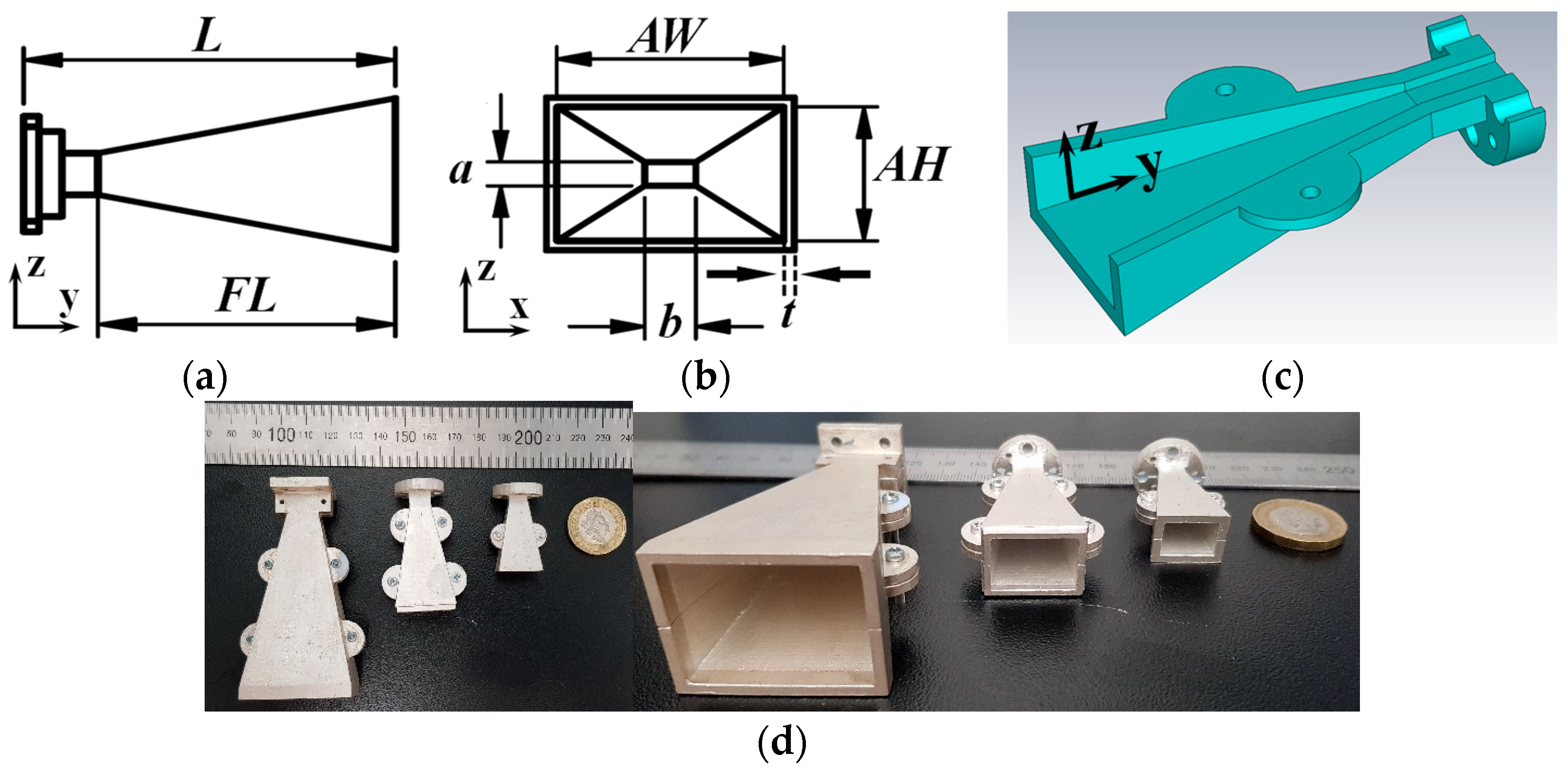
2. Antenna Structure

Three standard gain horn antennas were designed, modelled, and 3D printed. All of these antennas are based on solid metallic standard gain horn antennas manufactured by Flann Microwave Limited. This was done to provide an accurate performance comparison between the proposed 3D–printed horn antennas and commercially available metallic counterparts providing very high levels of performance. The three horns are: WR28 Model 22240–20 (26–40 GHz), WR15 Model 25240–20 (50–76 GHz), and WR10 Model 27240–20 (74–110 GHz). Figure 1 shows the 3D–printed prototypes. Table 1 gives the detailed dimensions of each horn antenna.

3. Manufacturing Method

3.1. 3D–Printing

The horn antennas were 3D–printed using an Objet30 3D printer. Objet30 is a polyjet 3D–printer that prints using VerloWhite plus material. The printing resolution is nearly 100 μm and the layer thickness is 16 μm. Each horn is 3D–printed in two identical parts and is split along the middle in the x–z plane. This avoids the need to use support material in the interior parts of the horn. In turn this guarantees a very smooth surface finish on the interior of the horn. Small 2 mm metallic screws are used to join each of the two horn parts. Each 3D–printed part is washed using water and toothbrush to remove the support material from the outside surface. No further post processing steps are required.

3.2. Metallization

The 3D–printed horns are metallized using a Silver Conductive Paint (SCP) from the Electrolube Ltd, Ashby de la Zouch, United Kingdom. SCP provides a thin, smooth, adherent, flexible film having a high electrical conductivity. SCP consists of 45% silver blended in solvent material and it can be applied on a variety of substrates, including plastics, paper, wood, textiles, glass, ceramics, and metals [32]. The metallization process used in this work simply involves manually painting each of parts of the horn antenna using a fine paint brush. Each part is manually painted with two coats to guarantee full paint coverage. The painted parts were left to dry for 10 min at room temperature after each coat. Each horn was then assembled using the metallic screws, mentioned earlier. A very small gap was observed between the two parts of the horn after assembly. Nevertheless, this gap is covered using two additional coats of paint. Applying further paint, to the gap between the two halves, after assembly is essential to guarantee high performance and will be discussed in the result section.

3.3. Metallic Horns

The metallic horns are standard gain horn antennas commercially available from Flann Microwave LTD and they are fabricated by micromachining metals followed by gold plating the interior of each horn antennas.

3.4. Mechanical and Thermal Properities of the 3D–Printed Antennas

VeroWhite Plus is a photopolymer material that is becomes rigid, durable, and possesses excellent mechanical properties after 3D printing [33]. VeroWhite Plus is commonly used in the Stratasys Objet30 3D printer, where it serves as the base resin—a photosensitive liquid polymer. During the printing process, this liquid is solidified layer by layer using UV light in a method known as photopolymerization. The result is a rigid, highly detailed 3D–print with characteristics comparable to injection–moulded plastics. The final product has a plastic–like appearance with a naturally smooth, opaque surface and a high degree of rigidity. For instance, the material’s tensile strength is measured at 50–60 MPa, and its flexural strength exceeds 60 MPa [1]. Moreover, VeroWhite Plus has a heat deflection temperature (HDT) of approximately 45–50 °C under a 1.82 MPa load. Under normal conditions—i.e., without external pressure—it is expected to handle higher temperatures above 50 °C [33]. Furthermore, SCP paint used in metallization process operates effectively within a temperature range of −80 °C to 125 °C [32].
However, although the materials used to fabricate the 3D–printed antennas are rigid and durable, the 3D–printed horn antennas are expected to be more susceptible to degradation and to have a shorter lifespan than metallic horn antennas, due to their polymer–based composition. In addition, one of the disadvantages of the proposed 3D–printed horn antennas that it is expected to be able to handle less radio frequency (RF) power in comparison to metallic horns. In fact, it is expected that the 3D–printed horns can handle a considerable amount of RF power—on the order of several tens of watts, and possibly higher, because VeroWhite plus material can withstand heat and temperature higher than 50 °C, while the SCP paint can withstand temperature up to 125 °C.

3.5. Fabrication Cost

Objet30 3D printer uses Verowhite material with material cost of 230 USD per Kg and 110 USD per Kg for the support material. This 3D printer is very useful for manufacturing mm–wave devices since the size and weight of the printed structures are small and light. Unlike metallic standard gain horns, whose price increases as the frequency goes high due to fabrication challenges, this approach shows that the cost of fabricating 3D printed antennas goes down as the frequency increases. For example, the cost of the material used to 3D print any of the three horns antennas used in this work is below 6 USD, as summarized in Table 2. Furthermore, the SCP paint, which is used to metallize the prototypes, is commercially available at a cost of ~ 16 USD per 3 g bottle. A single 3 g bottle was sufficient to metallize all of the proposed horns antennas. Hence, the total cost of the material used to fabricate any of the proposed horns antennas is less than 12 USD which is significantly much less than the commercial sale price of any of metallic counter parts. Additionally, the proposed fabrication method can be implemented using different 3D–printing techniques and 3D–printers. Those 3D–printers have similar fabrication accuracies, surface roughness’s, and material costs to the Objet30 printer used in this work. This includes for instance: SLA, and DLP based 3D–printers.

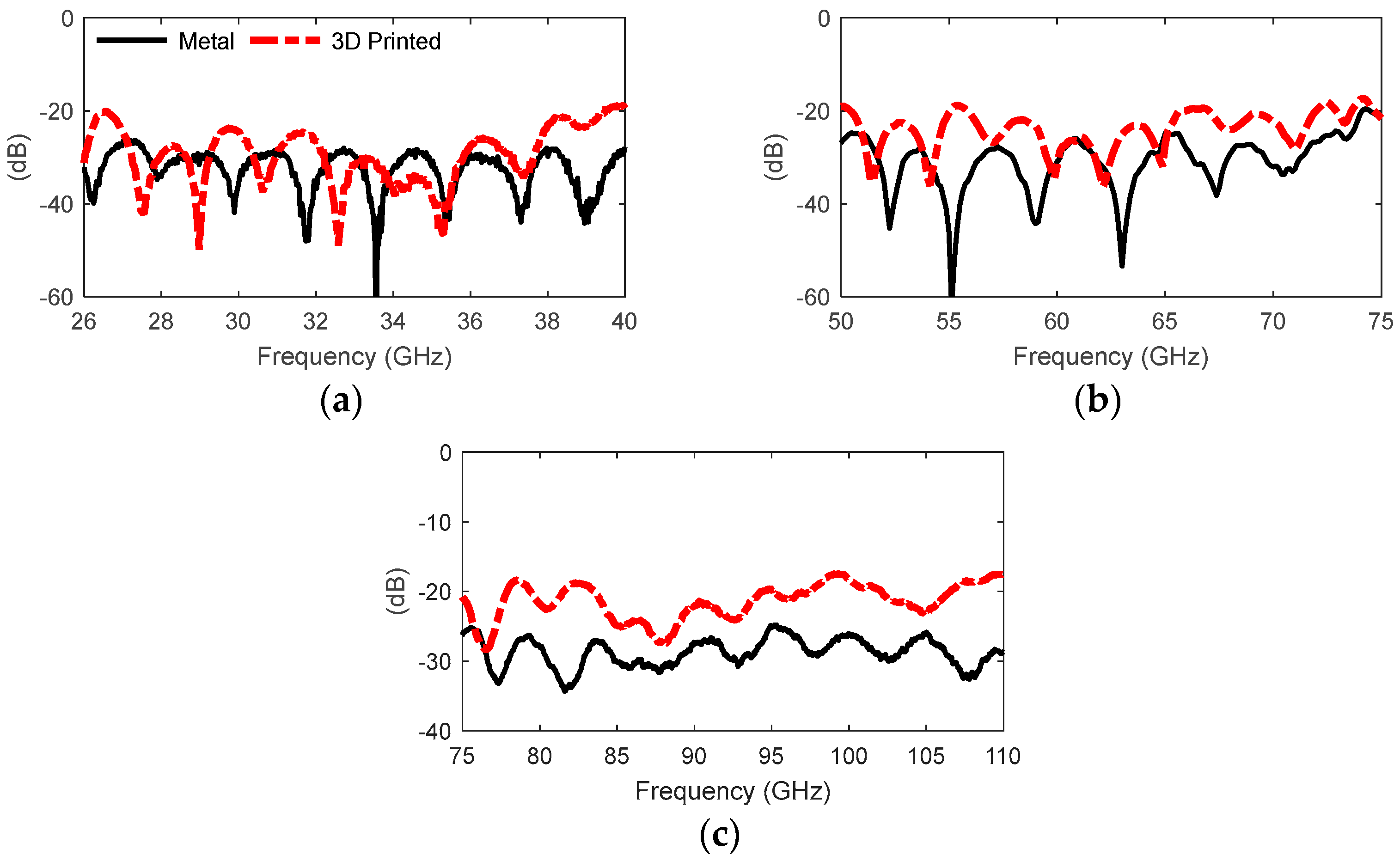
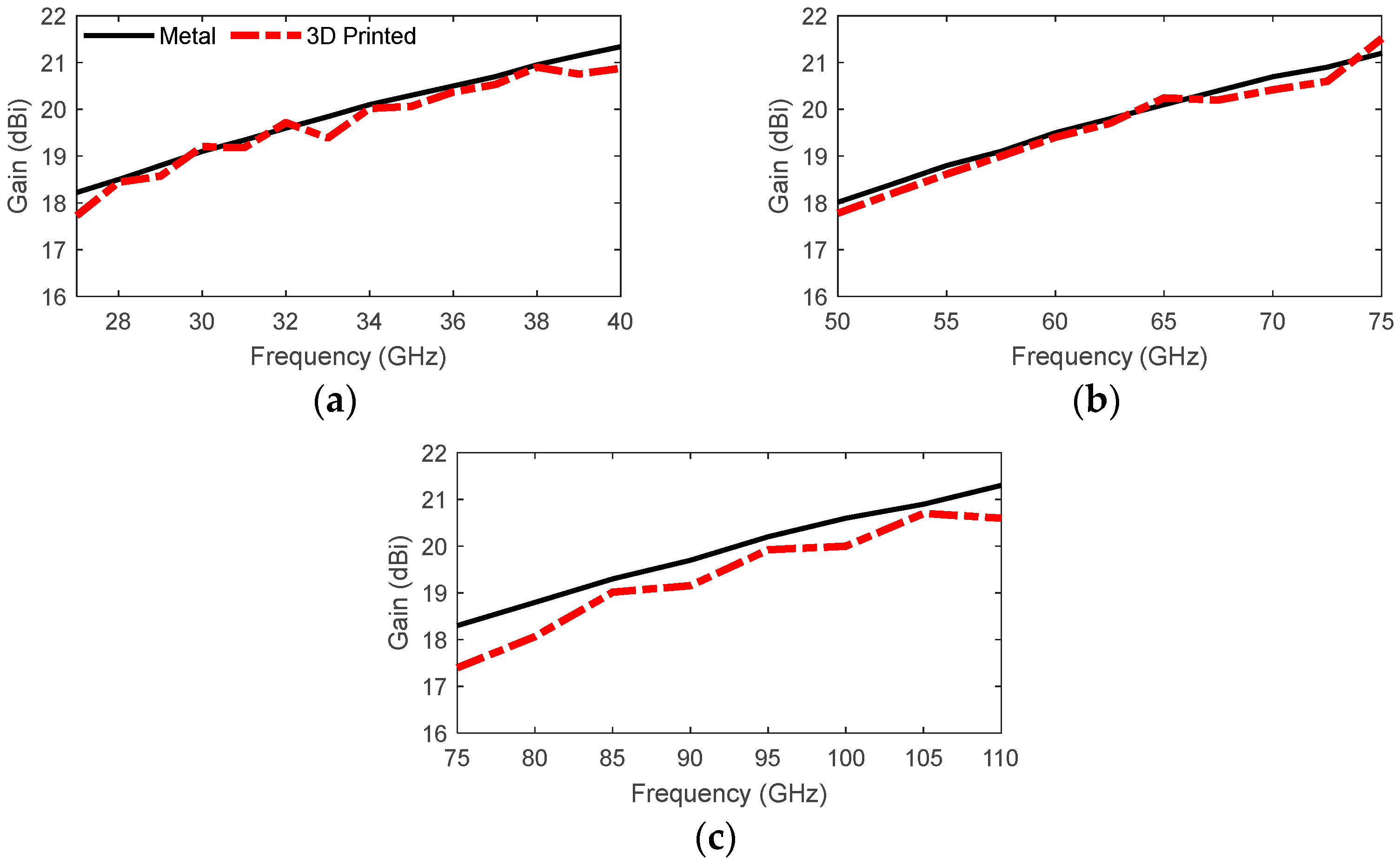
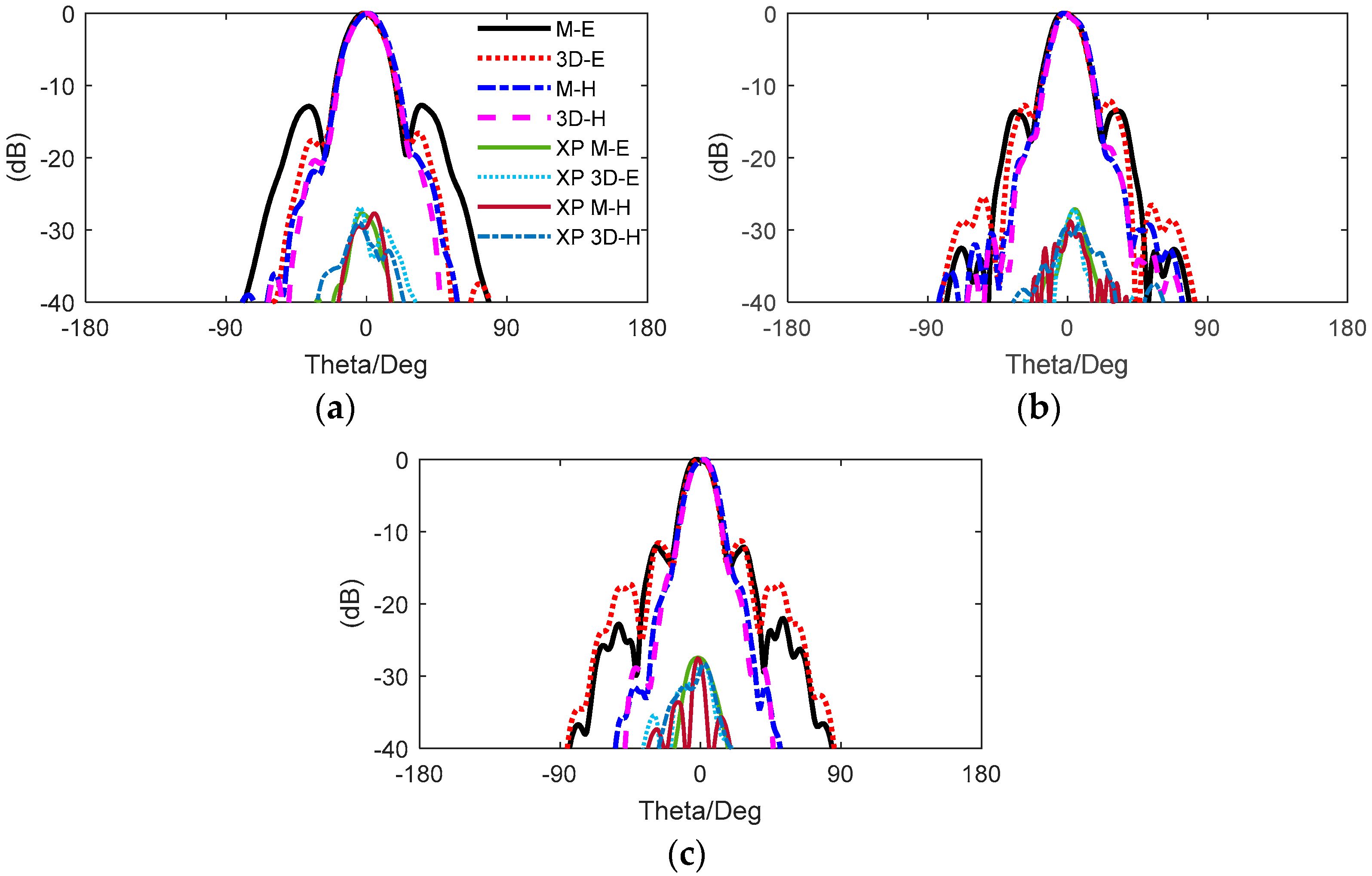
4. Results and Discussion

This section presents and compares the simulation and measurement results for the horn antennas. The reflection coefficients ( S 11 ), gains, and radiation patterns for all of 3D–printed and commercially available horns were measured and compared.
The S 11 parameters were measured using an Agilent PNA–X network analyzer and millimeter–wave frequency extenders, enabling S 11 measurements of waveguide–based antennas up to 500 GHz. Standard rectangular waveguide calibration kits —including WR28 kit, WR15 kit, and WR10 Kit—were used to perform individual Thru–Reflect–Line (TRL) calibrations for each horn frequency band. These calibrations were then used to measure the S 11 performance of both metallic and 3D–printed horn antennas. Furthermore, the radiation patterns and gains of all the horn antennas were measured using the 200 V NSI system, as shown in Figure 2. X. The 200 V NSI is a planar near–field scanner that enables effective measurement of gain and far–field radiation patterns for directive antennas. The antenna under test (AUT) was mounted on a fixed holder, positioned at a distance of n = 3–4 λ mm from the 200 V NSI system, where λ is the wavelength at the center frequency of each horn. The planar scanner uses a probe to perform a raster scan in the X and Y directions across the antenna surface, sampling the near–field data. These near–field samples are then converted into far–field radiation patterns using 200 V NSI software, which applies a Fourier transform algorithm. Moreover, the antenna gain is measured and calculated using the gain transfer/comparison method, as described in detail in [34].
The measurement results, are shown in Figure 3, Figure 4, Figure 5, Figure 6 and Figure 7. There is a very good agreement between the measured S 11 of the metallic and 3D printed horns, as seen in Figure 3. In more detail, the measured S 11 of the 22240–20 3D–printed horn is below −20 dB over the entire operational bandwidth, and it is below −25 dB over a 10.9 GHz bandwidth ranging from 27 GHz to 37.9 GHz. In comparison, the measured S 11 of the 22240–20 metallic horn is below −26 dB across the entire frequency band, as shown in Figure 3a. In addition, the measured S 11 of the 25240–20 3D–printed horn is below −18 dB across the entire operational bandwidth, as shown in Figure 3b. Furthermore, the measured S 11 is below −22 dB over the majority of the band, specifically within the frequency ranges of 50.6–55 GHz, 55.9–65.5 GHz, and 67.1–71.6 GHz as shown in Figure 3b. However, the measured S 11 of the 22540–20 metallic horn is below −24.5 dB across the entire frequency band, except at frequencies above 73 GHz. Moreover, the measured S 11 of the 27240–20 3D–printed horn is below −18 dB over the entire operational bandwidth and below −20 dB within the frequency ranges of 75–78 GHz, 79.4–81.5 GHz, 83.6–94.2 GHz, 95.2–97.5 GHz, and 102.1–106.7 GHz. In contrast, the measured S 11 of the 27240–20 metallic horn remains below −24.7 dB across the entire frequency band.
Figure 4 shows that there is a good agreement between the measured gain performance of 3D–printed and metallic horn antennas, where all 3D–printed horn antennas have marginally lower gain compared to the metallic horns. For example, the average difference in the measured gain of the 22240–20 3D–printed horn is 0.21 dB lower than that of the metallic horn over the entire operational bandwidth. The maximum gain difference is 0.5 dB, occurring over small frequency ranges of 27–27.5 GHz, 32.7–33.3 GHz, and 38.7–40 GHz. In addition, the average difference in the measured gain of the 25240–20 3D–printed horn is 0.28 dB lower than that of the metallic horn over the entire operational bandwidth, and the maximum gain difference is 0.45 dB over the frequency range of 68.5–72.5 GHz, as shown in Figure 4b. Furthermore, Figure 4c shows that the average difference in the measured gain of the 27240–20 3D–printed horn is 0.6 dB lower than that of the metallic horn over the entire operational bandwidth. The maximum gain difference is 1 dB over the frequency range of 75–77.5 GHz, while the gain difference is below 0.8 dB over the frequency range of 108–110 GHz.
Furthermore, there is excellent agreement between the half power beam width (HPBW) of the metallic and 3D–printed horn antennas, over the entire frequency band, in both the E–plane and H–plane, as shown in Figure 5, Figure 6 and Figure 7. In addition, the measured side lobe level (SLL) performance is almost identical in the H–plane for all 3D–printed horn antennas and their metallic counterparts. The measured SLL remains below −11 dB for all of the 3D–printed horn antennas in E–plane and below −20 dB in H–plane. However, the E–plane SLL performance of both the 22240–20 and the 25240–20 3D–printed horns is 0.5–1.2 dB higher than that of the metallic horns, as shown in Figure 5 and Figure 6. The E–plane SLL performance of the 27240–20 3D–printed horn is 0.6–1.7 dB higher than that of the metallic horn, as shown in Figure 7.
In addition, the cross–polarization (X–Pol) levels for the 3D–printed antennas are low and consistent with the performance of the metallic horn antennas. In more detail, the X–Pol of the 22240–20 metallic horn is less than 27.1 dB, while it is less than 28.5 dB for its 3D–printed counterpart as shown in Figure 5. Similarly, the X–Pol of the 25240–20 metallic horn is below 27.5 dB, and below 26.9 dB for the 3D–printed version as shown in Figure 6. In addition, Figure 7 shows that the 27240–20 metallic horn X–Pol is below 23.1 dB, while the 3D–printed version has an X–Pol lower than 23.4 dB.
The discrepancies between the performance of the measured 3D printed horns and the metallic horns can be attributed to a combination of several factors. Firstly, conduction losses of the paint have the most significant and direct effect on the gain performance of the 3D–printed horn antennas. The conductivity of the paint is significantly lower than that of the gold plating used in the commercially available metallic horns. SCP paint has 45% silver content and is mixed with 55% dielectric solvent blend that provides excellent adhesive properties. This dielectric material contributes to the conduction losses.
The conductivity of the SCP paint is specified in terms of its sheet resistance R s . This information can be used to analyze its effect on the performance of the antenna. R s is measured in ohm per square ( Ω / ) and it is expressed as: R s = ρ t , where ρ is the resistivity ( Ω ) and t is the thickness of the paint, and the conductivty is σ = 1 ρ = / m . R s can be measured, at dc, using the four point probe method. The thickness of the paint was measured, in–house, using a contact profilometer. The thickness of the two coats of the SCP paint was found to range from 30 μm to 45 μm, while the measured sheet resistance at dc was found to ranges from 13 m Ω / to 27 m Ω / . This corresponds to conductivity range of 0.82 × 10⁶ S/m to 2.6 × 10⁶ S/m [3,4]. Simulation results shows that the variation in conductivity has no effect on the S 11 performance of any of the horn antennas, as shown in Figure 8a–c.
However, the conductivity of the paint has a direct effect on the gain performance of all of the horn antennas, as shown in Figure 9a–c. For example, the average gain loss in the 22240–20 and 25240–20 horn antennas ranges from 0.2 dB to 0.4 dB as shown in Figure 9a,b. Whereas, the average gain loss, in the 27240–20 horn antenna ranges between 0.2 dB and 0.5 dB in the case of the 27240–20 horn antenna, as shown in Figure 9c. This can be attributed to the difference between the conductivity of the silver paint and that of gold, as the conductivity of the SCP paint ranges from 0.82 × 10 6 and 2.6 × 10 6   s / m .
The second factor that has a major effect on the S 11 and gain performance of the antennas is the application of paint after the assembly of the 3D–printed horn parts. Figure 10 shows that the presence of any gap larger than 20 μm in the case of 22240–20 and 25240–20 and larger than 10 μm in the case of 27240–20 severely affects the S 11 and gain performance of the horns. Hence, it is essential to paint the gap from the inside of the horns together with the exterior of the waveguide flanges after assembling the 3D printed horns, otherwise all horns will have a gain loss of more than 8 dB, as shown in Figure 11a–c. However, this process creates rounded corners at the waveguide interface of the horns especially in the case of 25240–20 and 27240–20, due to the waveguied sections being very small and also since the paint is applied manually using a brush. These rounded corners create a small mistmatch between the horn flanges and the waveguide feeding adaptors and have an effect on the measured S 11 performance, especially for 27240–20 and 25240–20 horns, as shown in Figure 3b,c.
Additional factors that have minor effects on the performance of the 3D–printed horns are the fabrication tolerances of the 3D–printer together with the surface roughness of the 3D–printed horn antennas. The 3D printer has a tolerance of 100 μm which corresponds to 0.01 λ at 30 GHz and to 0.033 λ at 100 GHz. In addition, it is expected that the surface roughness of the paint will have a minor effect on the performance of the horns as the 3D printed antennas have rougher surface than the metallic horn counterparts. The surface roughness of the material used to 3D print the horns was measured before and after application of the paint using a profilometer. The root mean square (RMS) value of the surface roughness for the 3D printed prototypes were found to be 1.83 μm with no paint and of 3.72 μm after application of the paint, as shown in Figure 12. This compares to 0.86 μm for the 27240–20 metal horn and a surface roughness of 0.84 μm for 22240–20 horn, while it is 0.89 μm for 25240–20 horn. Finally, the 3D printed horn antennas have on average 1 dB worst SLL level performance in the E–plane in comparison to the metallic horns, as shown in Figure 13. The main reason for this is that the 3D–printed horns are 1 mm thicker than the metallic ones. This was necessary to increase the robustness of the 3D–printed horns as they are printed using a plastic material which naturally has a lower stiffness than that of most metals.
Figure 14 shows that all metal based antennas have simulated efficiencies higher than 97% across all frequency bands. However, the simulated efficiencies of the 3D–printed antennas are expected to exceed 93% across all bands when the conductivity is 0.8 × 10 6 S/m, and it is expected to be higher than 95% when the conductivity is 0.8 × 10 6 S/m. This variation in the efficiencies of the 3D–printed horn antennas is due to the variation in the conductivity values of the SCP paint. Lower conductivity values lead to increased conduction losses, which in turn reduce the efficiencies of the 3D–printed horn antennas.

5. Conclusions

This paper presented a simple approach for manufacturing low cost horn antennas that operate at mm–wave frequencies. The approach involves 3D–printing and subsequent metallization. To validate the approach we have prototyped several standard gain horn antennas, operating over a frequency range, from 26 GHz to 110 GHz. Measurement results show that all of the proposed antennas are proven to operate satisfactorily with a level of performance that is very similar to their solid metal counterparts.

Author Contributions

Conceptualization, S.A.; Methodology, S.A.; Software, Z.U.K. and S.A.; Validation, Z.U.K. and A.A.S.; Formal analysis, S.A. and A.A.S.; Investigation, S.A.; Resources, S.F.J.; Writing—original draft, S.A., Z.U.K. and S.F.J.; Writing—review & editing, S.A.; Supervision, J.R.K. and A.A. All authors have read and agreed to the published version of the manuscript.

Funding

The Engineering and Physical Research Council [grant number EP/P008402/1, EP/P008402/2, and EP/V008420/1].

Data Availability Statement

All data generated or analyzed during this study are available within the article.

Conflicts of Interest

The authors declared no conflict of interest.

References

  1. Huang, G.; Zhou, S.; Sim, C.; Chio, T.; Yuan, T. Lightweight Perforated Waveguide Structure Realized by 3–D Printing for RF Applications. IEEE Trans. Antennas Propag. 2017, 65, 3897–3904. [Google Scholar] [CrossRef]
  2. Hajisaeid, E.; Dericioglu, A.F.; Akyurtlu, A. All 3–D Printed Free–Space Setup for Microwave Dielectric Characterization of Materials. IEEE Trans. Instrum. Meas. 2018, 67, 1877–1886. [Google Scholar] [CrossRef]
  3. Alkaraki, S.; Gao, Y.; Stremsdoerfer, S.; Gayets, E.; Parini, C.G. 3D Printed Corrugated Plate Antennas with High Aperture Efficiency and High Gain at X–Band and Ka–Band. IEEE Access 2020, 8, 30643–30654. [Google Scholar] [CrossRef]
  4. Alkaraki, S.; Gao, Y.; Torrico, M.O.M.; Stremsdoerfer, S.; Gayets, E.; Parini, C. Performance Comparison of Simple and Low Cost Metallization Techniques for 3D Printed Antennas at 10 GHz and 30 GHz. IEEE Access 2018, 6, 64261–64269. [Google Scholar] [CrossRef]
  5. Chieh, J.C.S.; Dick, B.; Loui, S.; Rockway, J.D. Development of a Ku–band Corrugated conical horn using 3–D print Technology. IEEE Antennas Wirel. Propag. Lett. 2014, 13, 201–204. [Google Scholar] [CrossRef]
  6. Hoel, K.V.; Ignatenko, M.; Kristoffersen, S.; Lier, E.; Filipovic, D.S. 3–D Printed Monolithic GRIN Dielectric–Loaded Double–Ridged Horn Antennas. IEEE Trans. Antennas Propag. 2020, 68, 533–539. [Google Scholar] [CrossRef]
  7. Wu, L.; Chu, H.; Cao, D.; Peng, S.; Guo, Y. 3–D Printed Antenna Subsystem with Dual–Polarization and its Test in System Level for Radiometer Applications. IEEE Access 2020, 8, 127856–127865. [Google Scholar] [CrossRef]
  8. Addamo, G.; Peverini, O.A.; Calignano, F.; Manfredi, D.; Paonessa, F.; Virone, G. 3–D Printing of High–Performance Feed Horns from Ku– to V–Bands. IEEE Antennas Wirel. Propag. Lett. 2018, 17, 2036–2040. [Google Scholar] [CrossRef]
  9. Lomakin, K.; Pavlenko, T.; Ankenbrand, M.; Ankenbrand, M.; Sippel, M.; Ringel, J.; Scheetz, M. Evaluation and Characterization of 3–D Printed Pyramid Horn Antennas Utilizing Different Deposition Techniques for Conductive Material. IEEE Trans. Compon. Packag. Manuf. Technol. 2018, 8, 1998–2006. [Google Scholar] [CrossRef]
  10. Liu, X.; Peng, L.; Liu, Y.-F.; Yu, W.-S.; Zhao, Q.-X.; Jiang, X. Ultra–broadband All Dielectric Transmit Array Designing Based on Genetic Algorithm Optimization and 3D Print Technology. IEEE Trans. Antennas Propag. 2021, 69, 2003–2012. [Google Scholar] [CrossRef]
  11. Le Sage, G.P. 3D printed waveguide slot array antennas. IEEE Access 2016, 4, 1258–1265. [Google Scholar] [CrossRef]
  12. Shin, S.; Alyasiri, D.F.; D’Auria, M.; Otter, W.J.; Myant, C.W.; Stokes, D. Polymer–Based 3–D Printed Ku–Band Steerable Phased–Array Antenna Subsystem. IEEE Access 2019, 7, 106662–106673. [Google Scholar] [CrossRef]
  13. Rashid, S.; Jofre, L.; Garrido, A.; Gonzalez, G.; Ding, Y.; Aguasca, A.; O’Callaghan, J.; Romeu, J. 3–D Printed UWB Microwave Bodyscope for Biomedical Measurements. IEEE Antennas Wirel. Propag. Lett. 2019, 18, 626–630. [Google Scholar] [CrossRef]
  14. Sarjoghian, S.; Sagor, M.H.; Alfadhl, Y.; Chen, X. A 3D–Printed High–Dielectric Filled Elliptical Double–Ridged Horn Antenna for Biomedical Monitoring Applications. IEEE Access 2019, 7, 94977–94985. [Google Scholar] [CrossRef]
  15. Zhang, B.; Wu, L.; Zhou, Y.; Yang, Y.; Zhu, H.; Cheng, F.; Chen, Q.; Huang, K. A K–Band 3–D Printed Focal–Shifted Two–Dimensional Beam–Scanning Lens Antenna with Nonuniform Feed cubest. IEEE Antennas Wirel. Propag. Lett. 2019, 18, 2721–2725. [Google Scholar] [CrossRef]
  16. Zhang, B.; Li, R.; Wu, L.; Sun, H.; Guo, Y. A Highly Integrated 3–D Printed Metallic K–Band Passive Front End as the Unit Cell in a Large Array for Satellite Communication. IEEE Antennas Wirel. Propag. Lett. 2018, 17, 2046–2050. [Google Scholar] [CrossRef]
  17. Rojas–Nastrucci, E.A.; Nussbaum, J.T.; Crane, N.B.; Weller, T.M. Ka–Band Characterization of Binder Jetting for 3–D Printing of Metallic Rectangular Waveguide Circuits and Antennas. IEEE Trans. Microw. Theory Tech. 2017, 65, 3099–3108. [Google Scholar] [CrossRef]
  18. Alkaraki, S.; Andy, A.S.; Gao, Y.; Tong, K.F.; Ying, Z.; Donnan, R.; Parini, C. Compact and Low–Cost 3–D Printed Antennas Metalized Using Spray–Coating Technology for 5G mm–Wave Communication Systems. IEEE Antennas Wirel. Propag. Lett. 2018, 17, 2051–2055. [Google Scholar] [CrossRef]
  19. Alkaraki, S.; Gao, Y. mm–Wave Low–Cost 3D Printed MIMO Antennas With Beam Switching Capabilities for 5G Communication Systems. IEEE Access 2020, 8, 32531–32541. [Google Scholar] [CrossRef]
  20. Agnihotri, I.; Sharma, S.K. Design of a 3D Metal Printed Axial Corrugated Horn Antenna Covering Full Ka–Band. IEEE Antennas Wirel. Propag. Lett. 2020, 19, 522–526. [Google Scholar] [CrossRef]
  21. Li, Y.; Ge, L.; Wang, J.; Da, S.; Cao, D.; Wang, J.; Liu, Y. 3–D Printed High–Gain Wideband Waveguide Fed Horn Antenna Arrays for Millimeter–Wave Applications. IEEE Trans. Antennas Propag. 2019, 67, 2868–2877. [Google Scholar] [CrossRef]
  22. Saeidi–Manesh, H.; Saeedi, S.; Mirmozafari, M.; Zhang, G.; Sigmarsson, H.H. Design and Fabrication of Orthogonal–Mode Transducer Using 3–D Printing Technology. IEEE Antennas Wirel. Propag. Lett. 2018, 17, 2013–2016. [Google Scholar] [CrossRef]
  23. Shen, J.; Ricketts, D.S. Compact W–Band “Swan Neck” Turnstile Junction Orthomode Transducer Implemented by 3–D Printing. IEEE Trans. Microw. Theory Tech. 2020, 68, 3408–3417. [Google Scholar] [CrossRef]
  24. Lu, K.; Leung, K.W.; Yang, N. 3D–Printed Circularly Polarized Twisted–ridge Horn Antenna. IEEE Trans. Antennas Propag. 2021, 69, 1746–1750. [Google Scholar] [CrossRef]
  25. Zhang, B.; Zirath, H. A Metallic 3–D Printed E–Band Radio Front End. IEEE Microw. Wirel. Compon. Lett. 2016, 26, 331–333. [Google Scholar] [CrossRef]
  26. Gu, C.; Gao, S.; Fusco, V.; Gibbons, G.; Sanz–Izquierdo, B.; Standaert, A.; Reynaert, P.; Bösch, W.; Gadringer, M.; Xu, R.; et al. A D–Band 3D–Printed Antenna. IEEE Trans. Terahertz Sci. Technol. 2020, 10, 433–442. [Google Scholar] [CrossRef]
  27. Wu, G.B.; Chan, K.F.; Qu, S.W.; Tong, K.F.; Chan, C.H. Orbital Angular Momentum (OAM) Mode–Reconfigurable Discrete Dielectric Lens Operating at 300 GHz. IEEE Trans. Terahertz Sci. Technol. 2020, 10, 480–489. [Google Scholar] [CrossRef]
  28. Shen, J.; Ricketts, D.S. Additive Manufacturing of Complex Millimeter–Wave Waveguides Structures Using Digital Light Processing. IEEE Trans. Microw. Theory Tech. 2019, 67, 883–895. [Google Scholar] [CrossRef]
  29. Tak, J.; Kantemur, A.; Sharma, Y.; Xin, H. A 3–D–Printed W–Band Slotted Waveguide Array Antenna Optimized Using Machine Learning. IEEE Antennas Wirel. Propag. Lett. 2018, 17, 2008–2012. [Google Scholar] [CrossRef]
  30. Zhang, B.; Zhan, Z.; Cao, Y.; Gulan, H.; Linner, P.; Sun, J.; Zwick, T.; Zirath, H. Metallic 3–D printed antennas for millimeter– and submillimeter wave applications. IEEE Trans. Teraherz. Sci. Technol. 2016, 6, 592–600. [Google Scholar] [CrossRef]
  31. Jammes, A.; Petisme, M.; Staelens, K. Metallization and selective metallization of silver by spraying. Surf. Coat. Technol. 2017, 332, 560–563. [Google Scholar] [CrossRef]
  32. Stratsys Ltd. Vero Material Data Sheet. Available online: https://www.stratasys.com/en/materials/materials-catalog/polyjet-materials/verovivid/ (accessed on 15 April 2025).
  33. Electrolube Ltd. Silver Conductive Paint (SCP) Technical Data Sheet. Available online: https://www.ulbrich.cz/chemical–technical–products/TDS_ELECTROLUBE_SCP_Silver_Conductive_Paint_eng.pdf (accessed on 15 April 2025).
  34. Balanis, C.A. Antenna measurement. In Antenna Theory, 3rd ed.; Wiley: Hoboken, NJ, USA, 2005; Chapter 17, Section 4.2; pp. 1033–1034. [Google Scholar]
Figure 1. Schematics and the fabricated 3D–printed horns. (a) schematics of side view (z–y planes), (b) schematics of front view (c) perspective view of cross section cut of thehorn and (d) photos of the fabricated prototypes.
Jmmp 09 00222 g001
Figure 2. Schematics of the measurement setup used to measure the radiation pattern and gain of the proposed antennas.
Jmmp 09 00222 g002
Figure 3. Measured reflection coefficient (S11) of the proposed 3D––printed horn antenna. (a) 22240–20 horns, (b) 25240–20 horns and (c) 27240–20 horns.
Jmmp 09 00222 g003
Figure 4. Measured Gain of the proposed 3D–printed horn antenna. (a) 22240–20 horns, (b) 25240–20 horns and (c) 27240–20 horns.
Jmmp 09 00222 g004
Figure 5. Measured Radiation Patterns of the 22240–20 horns. (a) 27 GHz H– and E–plane, (b) 33 GHz H– and E–plane, and (c) 39 GHz H– and E–plane. Caption key: M–E = metal horn E–plane, 3D–E = 3D printed horn E–plane, M–H = metal horn H–plane and 3D–H = 3D printed horn H–plane, XP = Cross polarization.
Jmmp 09 00222 g005
Figure 6. Measured Radiation Patterns of the 25240–20 horns. (a) 50 GHz H– and E–plane, (b) 60 GHz H– and E–plane, and (c) 70 GHz H– and E–plane.
Jmmp 09 00222 g006
Figure 7. Measured Radiation Patterns of the 27240–20 horns. (a) 80 GHz H– and E–plane, (b) 90 GHz H– and E–plane, and (c) 110 GHz H– and E–plane.
Jmmp 09 00222 g007
Figure 8. Simulated effect of conductivity of paint on S 11 of the proposed antenna. (a) 22240–20 horns, (b) 25240–20 horns and (c) 27240–20 horns.
Jmmp 09 00222 g008
Figure 9. Simulated effect of conductivity of paint on gain of the proposed 3D–printed antennas. (a) 22240–20 horns, (b) 25240–20 horns and (c) 27240–20 horns.
Jmmp 09 00222 g009
Figure 10. Simulated effect of potential gap (G) between both horn parts on S 11 performance of the proposed antennas. (a) 22240–20 horns, (b) 25240–20 horns and (c) 27240–20 horns.
Jmmp 09 00222 g010
Figure 11. Simulated effect of potential gap (G) between both horn parts on the gain performance of the proposed antennas. (a) 22240–20 horns, (b) 25240–20 horns and (c) 27240–20 horns.
Jmmp 09 00222 g011
Figure 12. The surface profile of the 3D printed plastics with/without paint and metal horn. RMS = 1.91 μm no paint and 3.72 μm after paint, RMS = 0.86 μm for the 27240–20 metal horn.
Jmmp 09 00222 g012
Figure 13. Effect of horn thickness (t) on the side lobe level performance in the E–plane. (a) 22240–20 horns, (b) 25240–20 horns and (c) 27240–20 horns.
Jmmp 09 00222 g013
Figure 14. Simulated efficiency of the proposed 3D printed horn antenna. (a) 22240–20 horns, (b) 25240–20 horns and (c) 27240–20 horns.
Jmmp 09 00222 g014
Table 1. Dimensions of the proposed 3D–printed horn antennas. (Dimensions are in MM).
22240–2025240–2027240–20
Length (L)86.0048.032.50
Aperture width (AW)34.2018.5012.40
Aperture height (AH)24.8012.809.00
Waveguide Width (b)7.1123.7592.540
Waveguide height (a)3.5561.8801.270
Flare Length (FL)75.0038.0026.00
Thickness (t)—3D printed222
Thickness (t)—Metal0.911.1
Table 2. Summary of the approximated cost of material used to fabricate the proposed 3D–Printed horns [the horn weight excludes the metallic screws].
Weight
(Grams)
Material
Cost (USD)
Metallization Cost
(USD)
22240–20 Horn22.4≈5.6≈5.6
25240–20 Horn9.1≈2.3≈2.3
27240–20 Horn4.72≈1.2≈1.2
Disclaimer/Publisher’s Note: The statements, opinions and data contained in all publications are solely those of the individual author(s) and contributor(s) and not of MDPI and/or the editor(s). MDPI and/or the editor(s) disclaim responsibility for any injury to people or property resulting from any ideas, methods, instructions or products referred to in the content.

