
Physics-Informed Preform Design for Flashless 3D Forging via Material Point Backtracking and Finite Element Simulations


Abstract
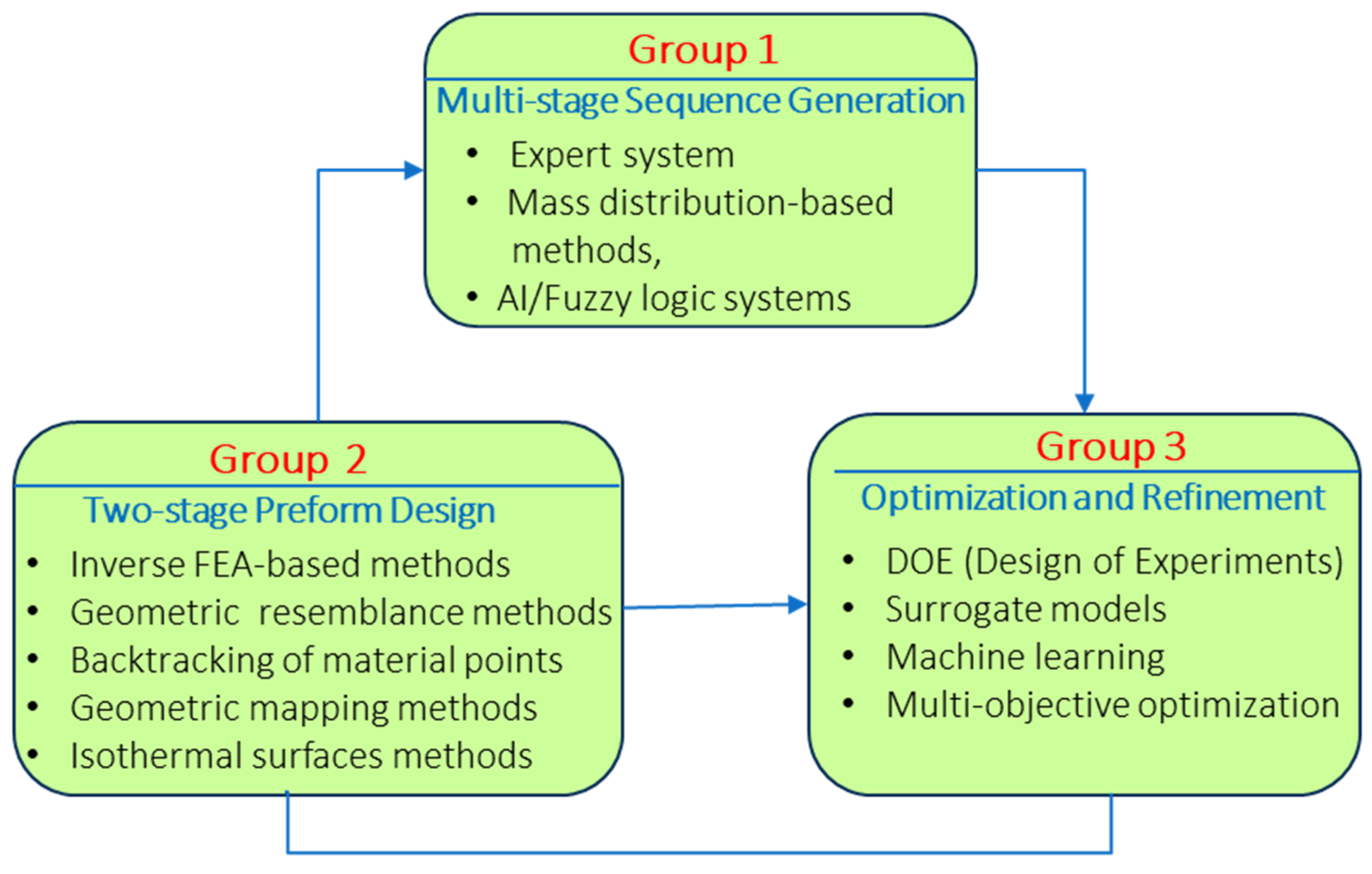
1. Introduction
1.1. Group 1: Multi-Stage Sequence Generation
1.2. Group 2: Two-Stage Forging Preform Design
1.3. Group 3: Optimization and Refinement
1.4. Integration and Research Outlook
2. Methodology
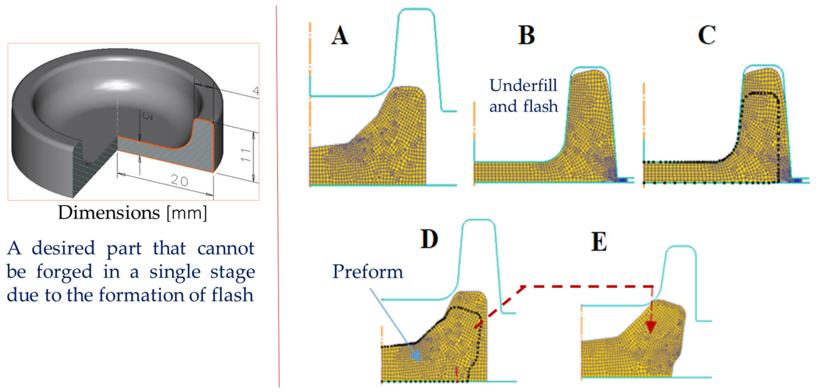
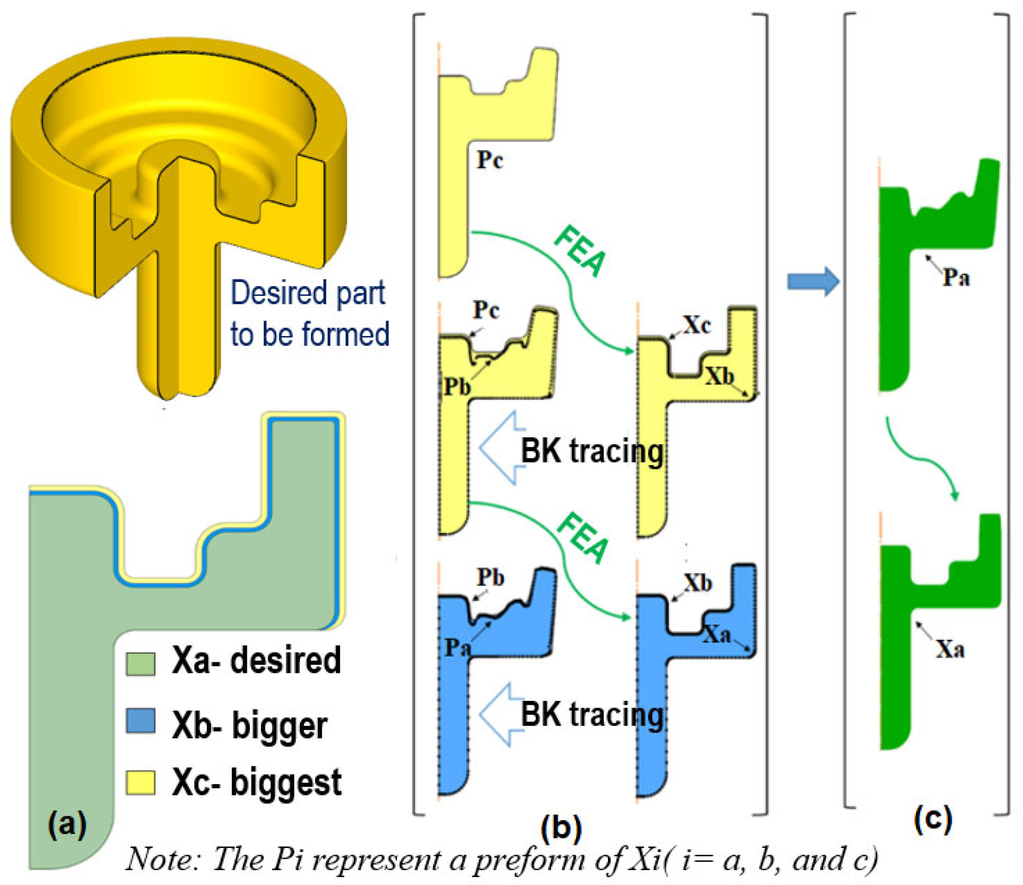
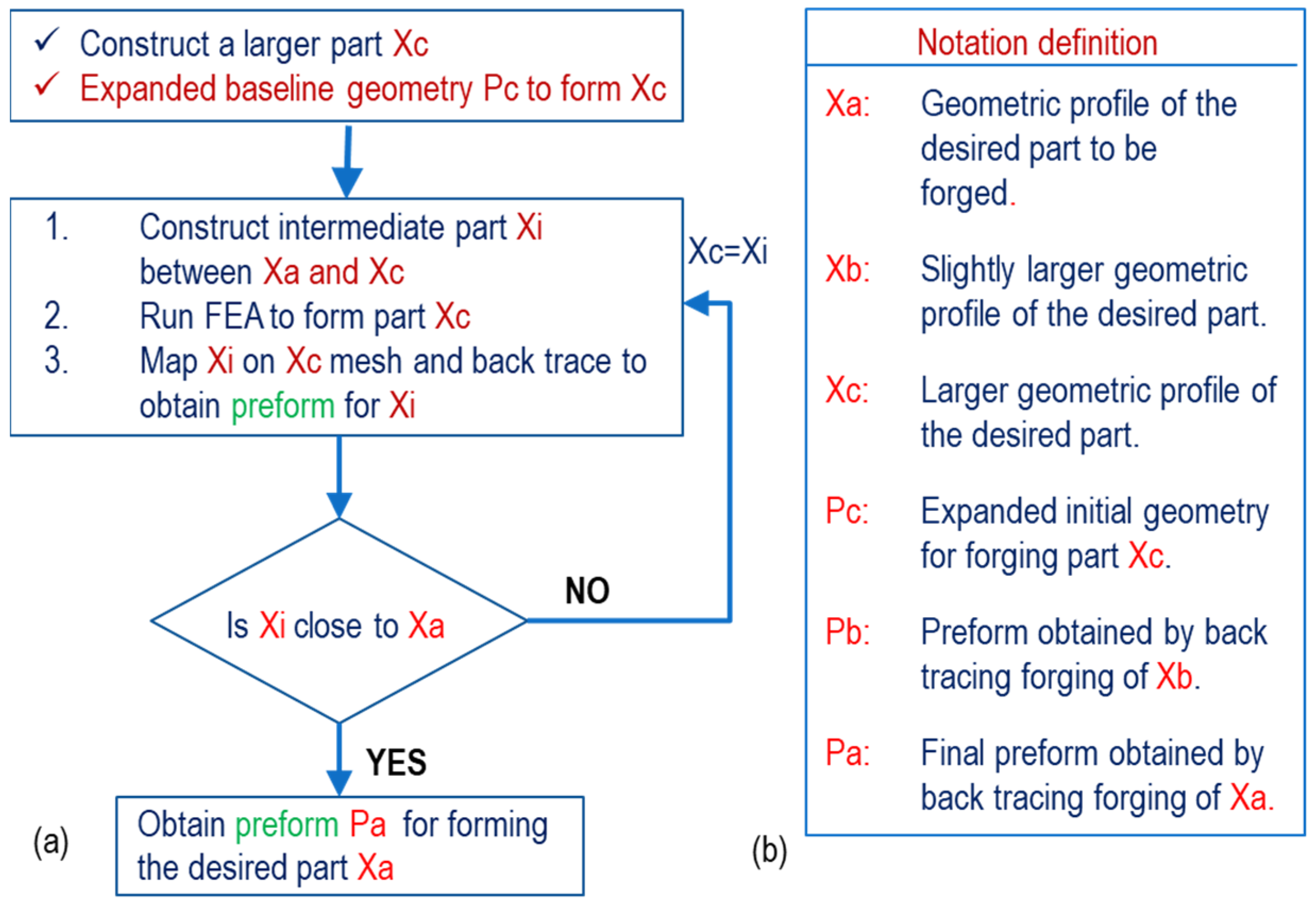
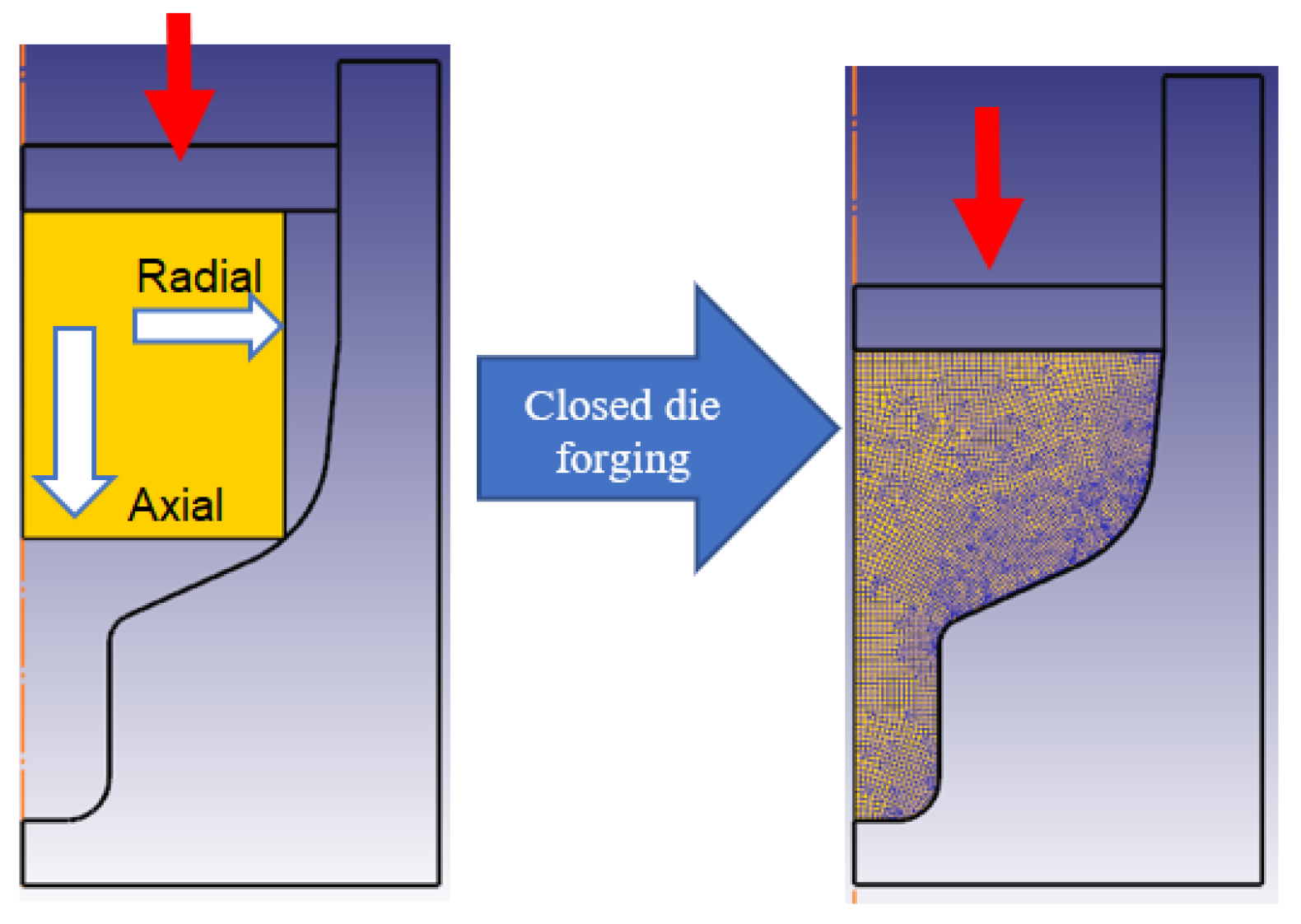
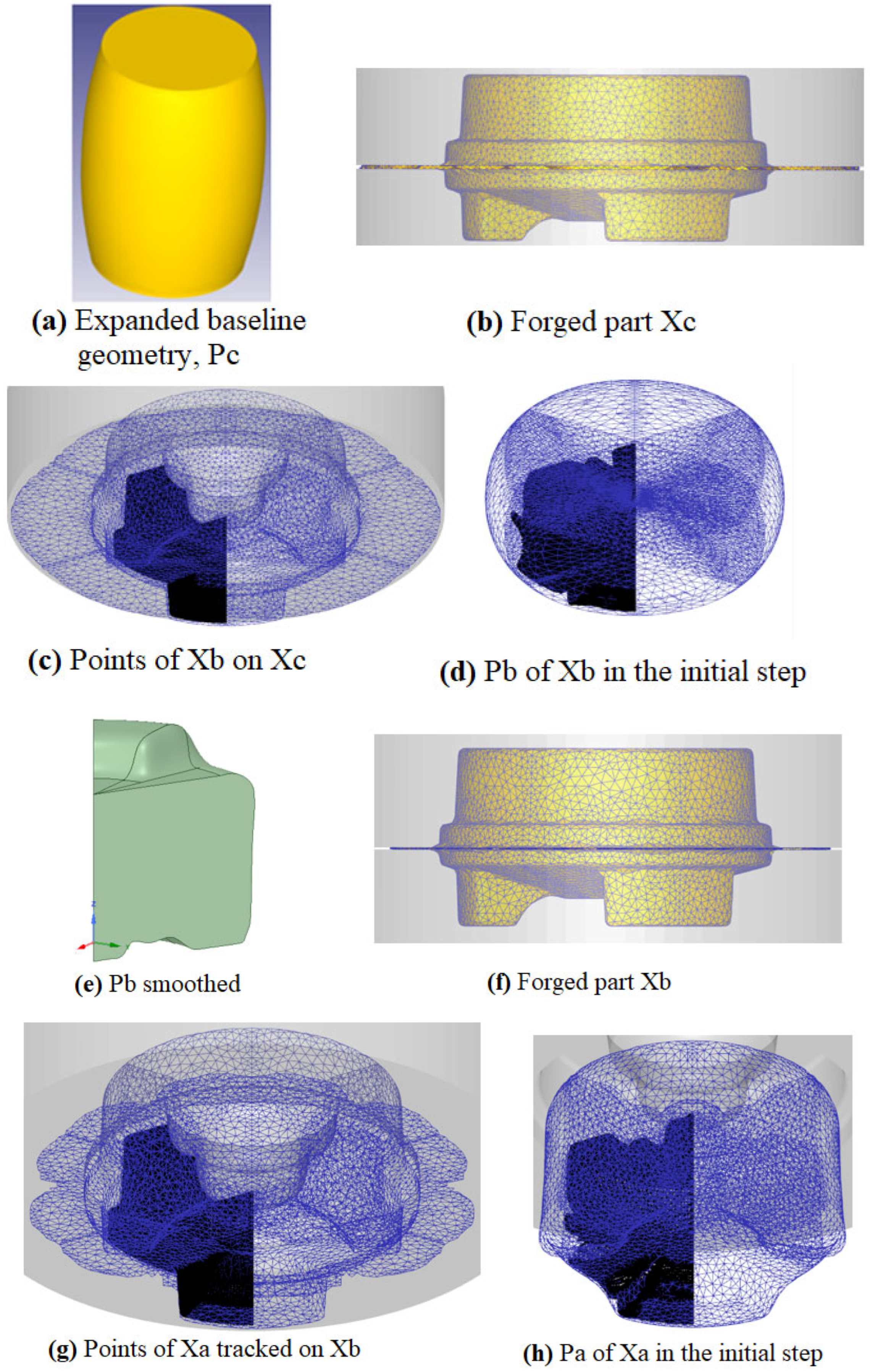
2.1. Principle of the Preform Design Using Geometrical Resemblance
- (i)
- Define the desired part geometry as Xa. Construct an oversized, geometrically similar part Xc as an initial target.
- (ii)
- Employ an expanded baseline preform Pc to forge part Xc. While Xc may exhibit defects such as underfill or flash, it must completely enclose an intermediate part Xb.
- (iii)
- Identify the geometry Xb and trace its boundary points backward from Xc to preform Pc to define the intermediate preform Pb.
- (iv)
- Construct a new intermediate geometry Xi that closely resembles Xa. Backtrack the material points of Xi from its forging step (preform Pb) to define a new preform Pi.
- (v)
- Repeat step (iv) iteratively until Xi closely approximates Xa. The final preform Pa is determined by tracing material points of Xa back to the forging step associated with Pi.
2.2. Preform Design for Three-Dimensional Parts
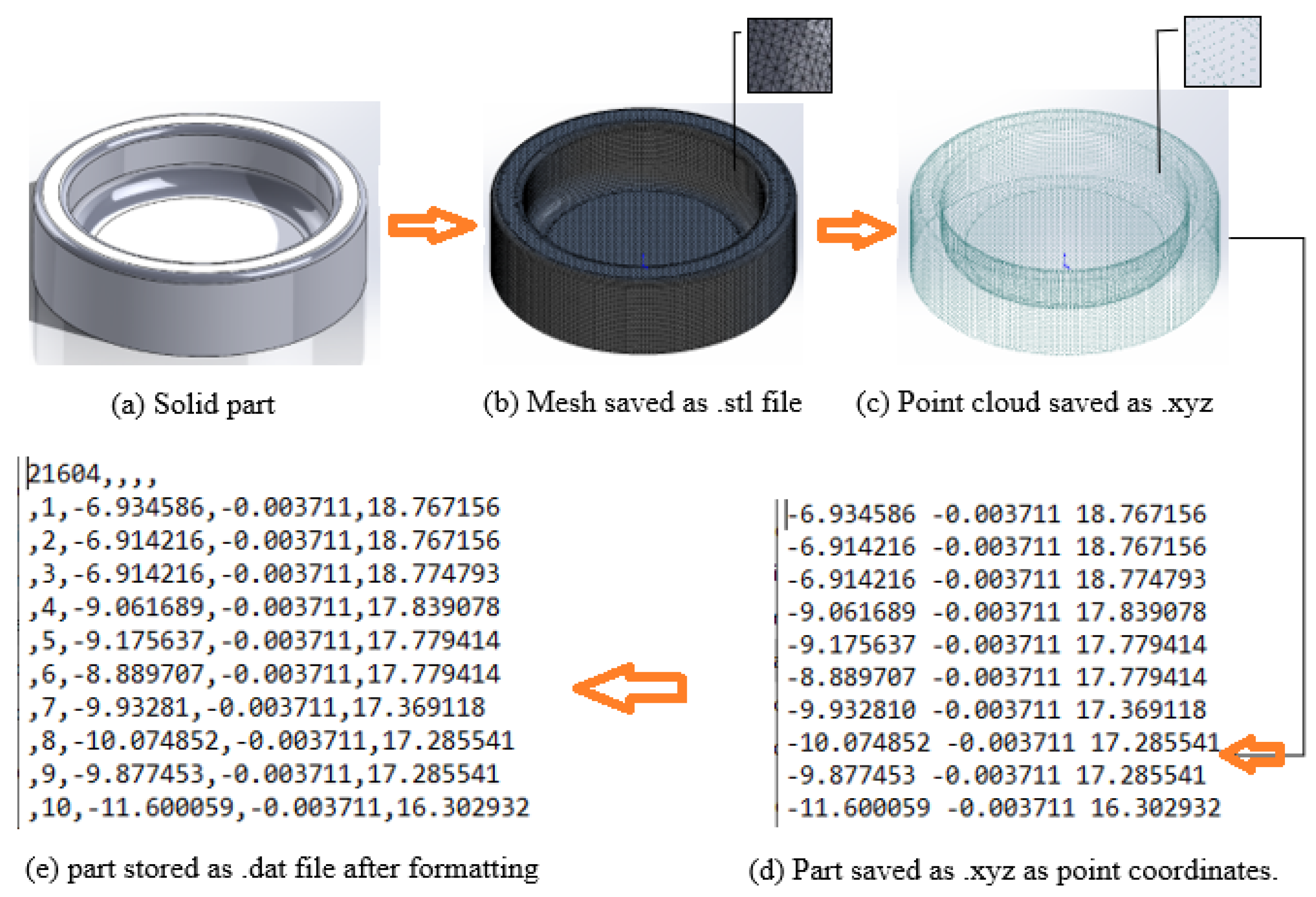
2.2.1. Material Point Generation and Mapping for Backtracking
- (i)
- (ii)
- The STL file is exported as an xyz file to generate a point cloud (Figure 7c).
- (iii)
- (iv)
- The formatted data is saved as a data file and imported into DEFORM 3D to enable material point backtracking through the simulated deformation process.
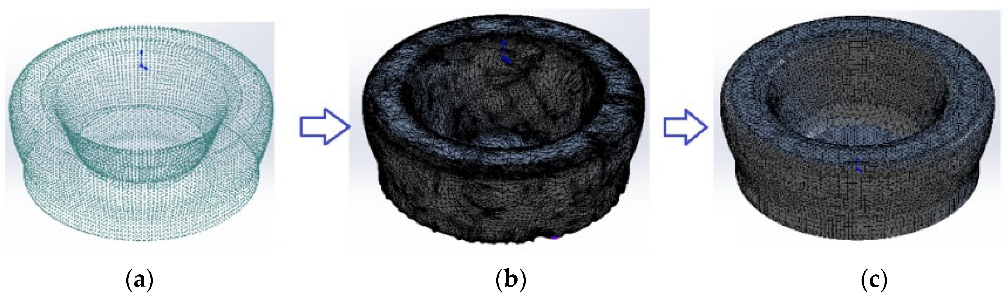
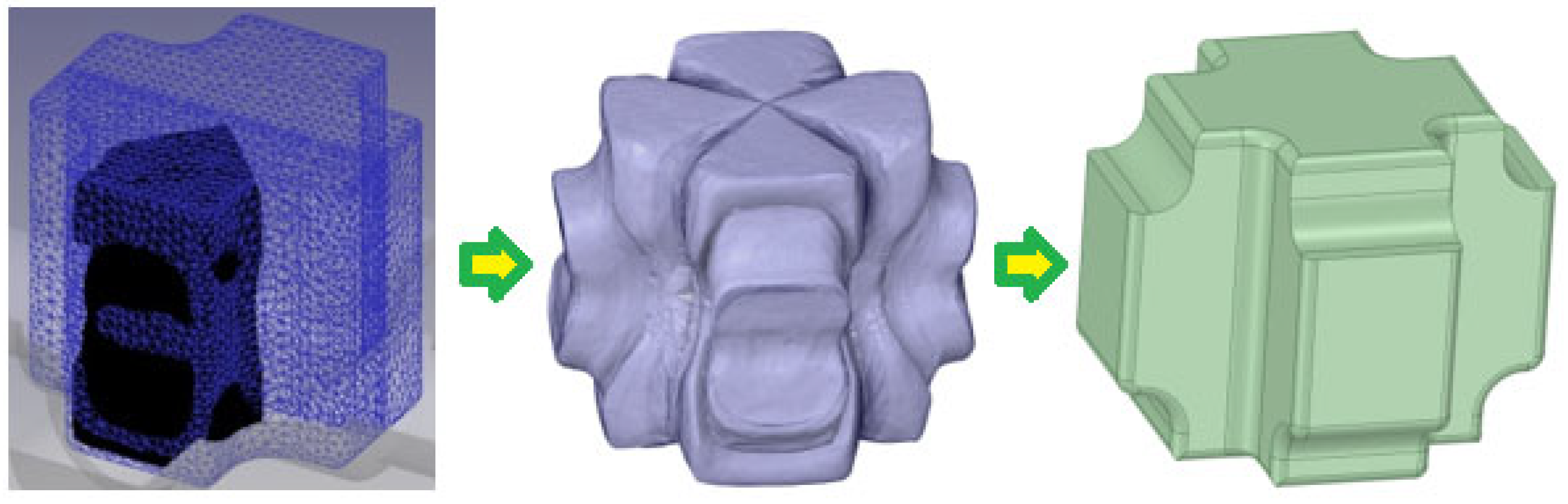
2.2.2. Reconstruction and Solid Modeling from Point Cloud Data
- (i)
- The backtracked points from DEFORM 3D are saved as an xyz file.
- (ii)
- The xyz file is imported into SolidWorks 2022 using the Mesh Prep Wizard to construct an initial mesh model (Figure 8b).
- (iii)
- The raw mesh may contain issues such as overlapping triangles or non-manifold edges. These are resolved using SpaceClaim, where the mesh is smoothed, repaired, and re-meshed (Figure 8c).
- (iv)
- The final clean geometry is saved as an STL file and used for the next iteration of FE simulation.
3. Application of the Preform Methodology for 3D Closed Die Forging Processes
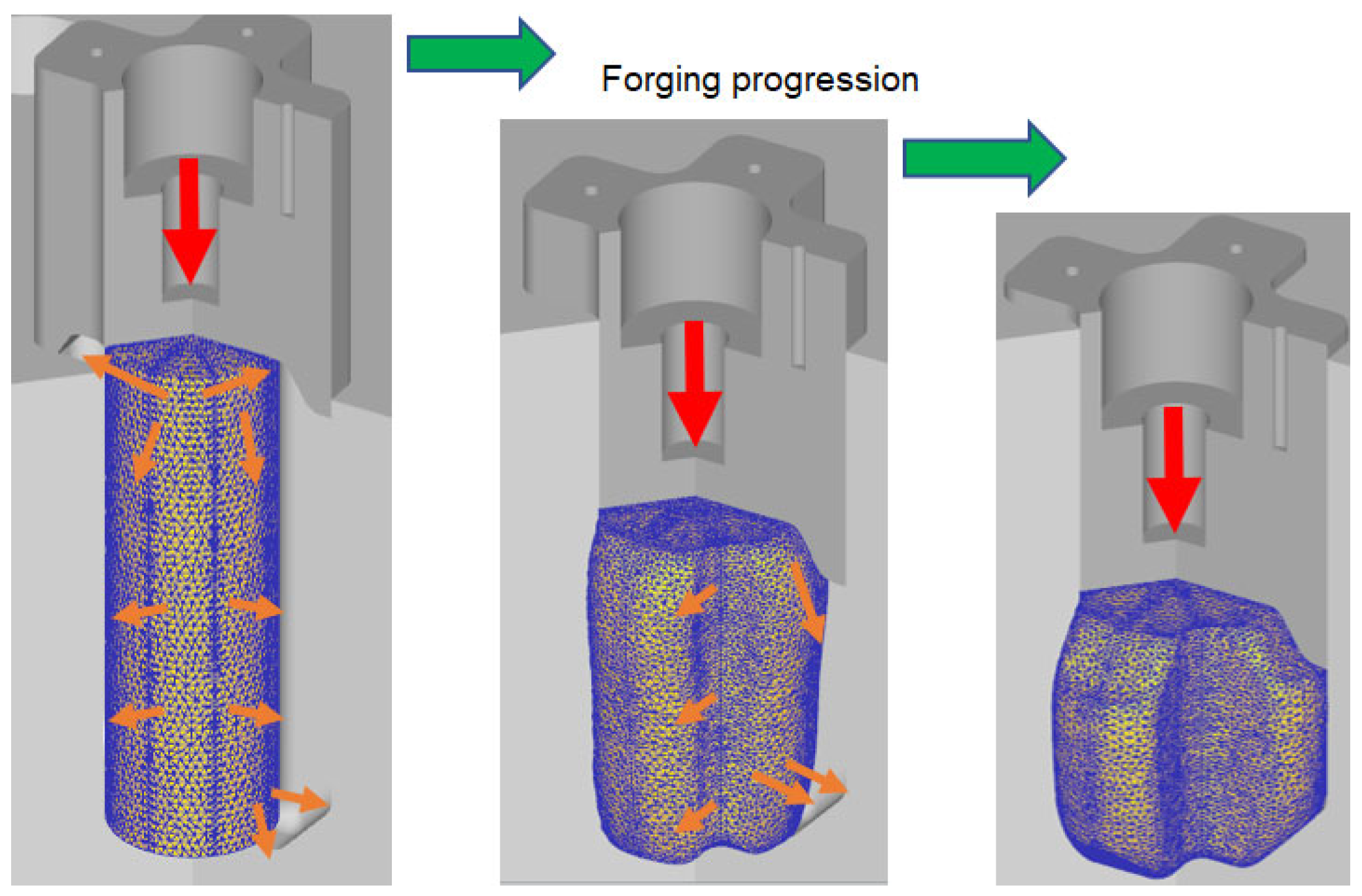
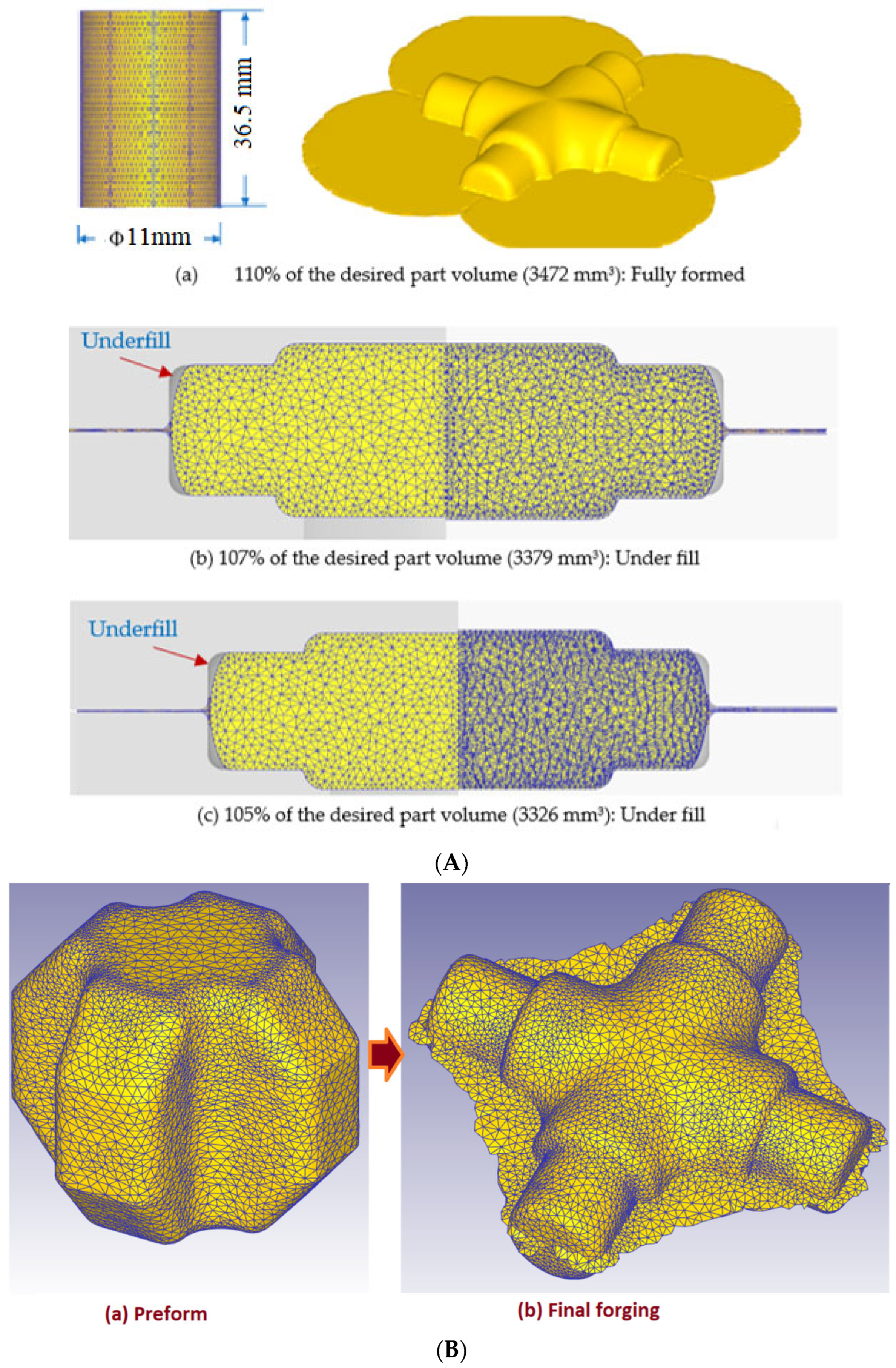
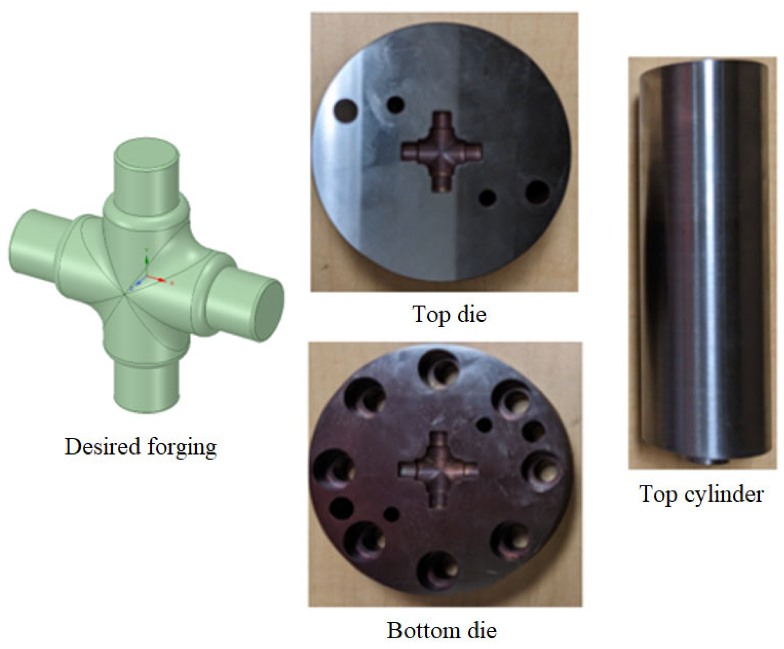
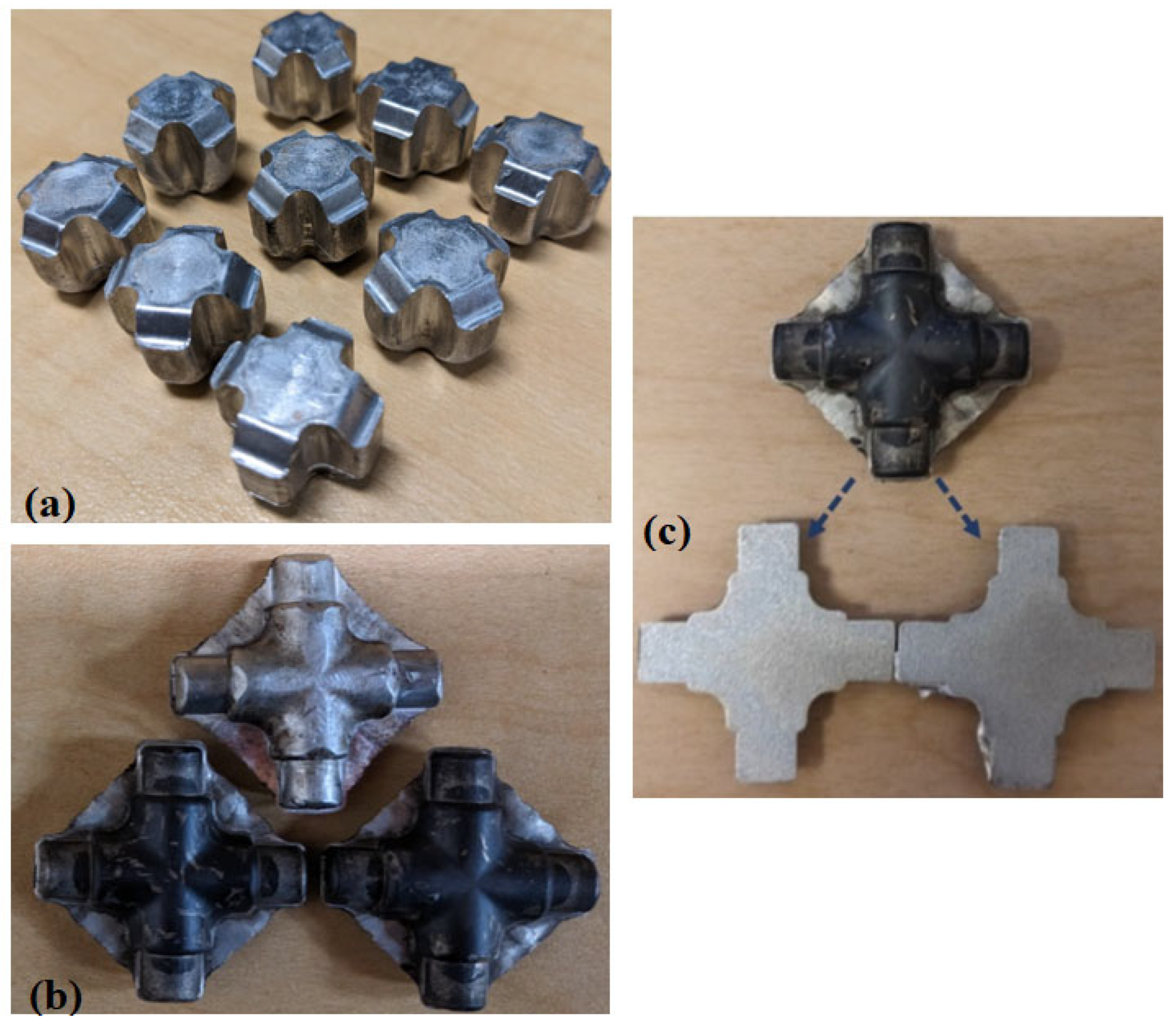
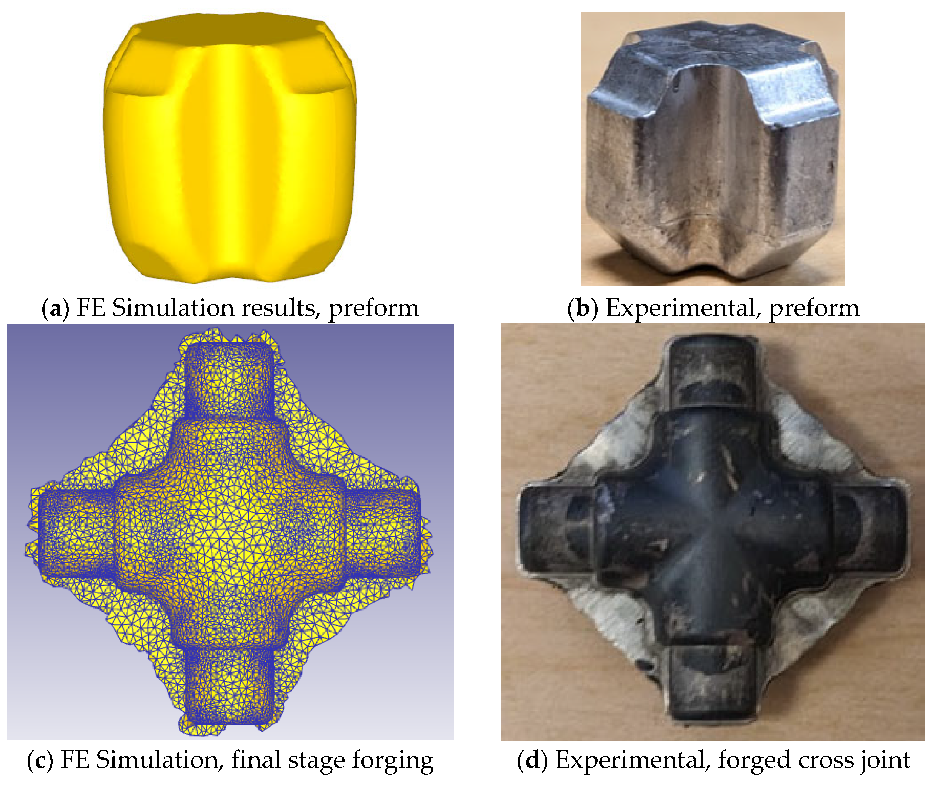
3.1. Cross-Joint Forging
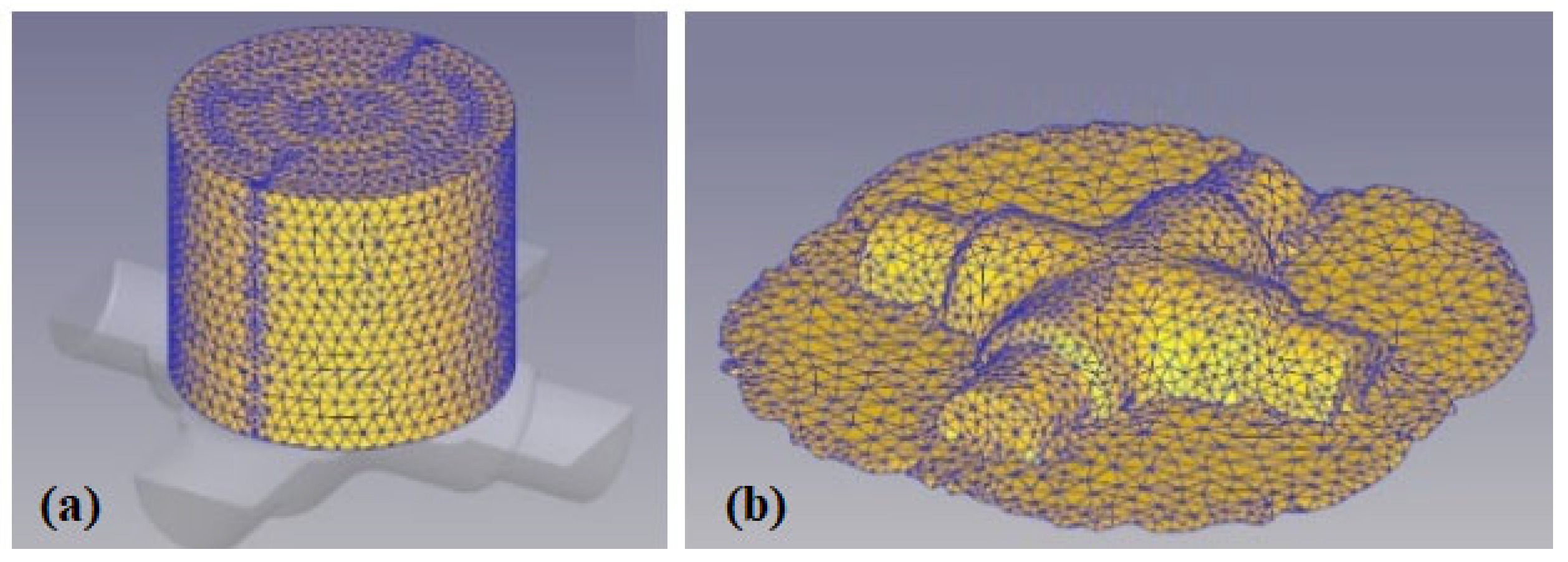
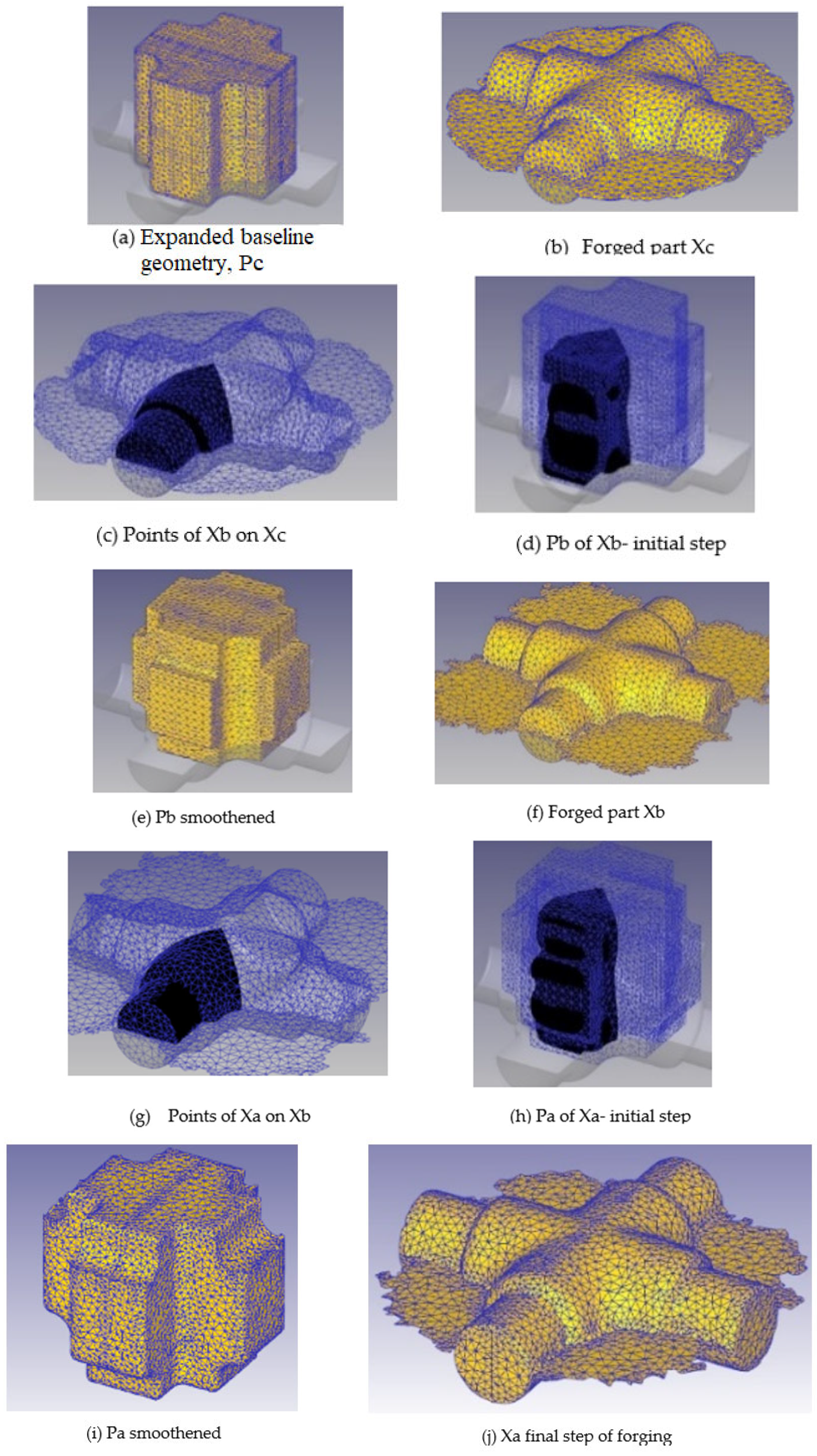
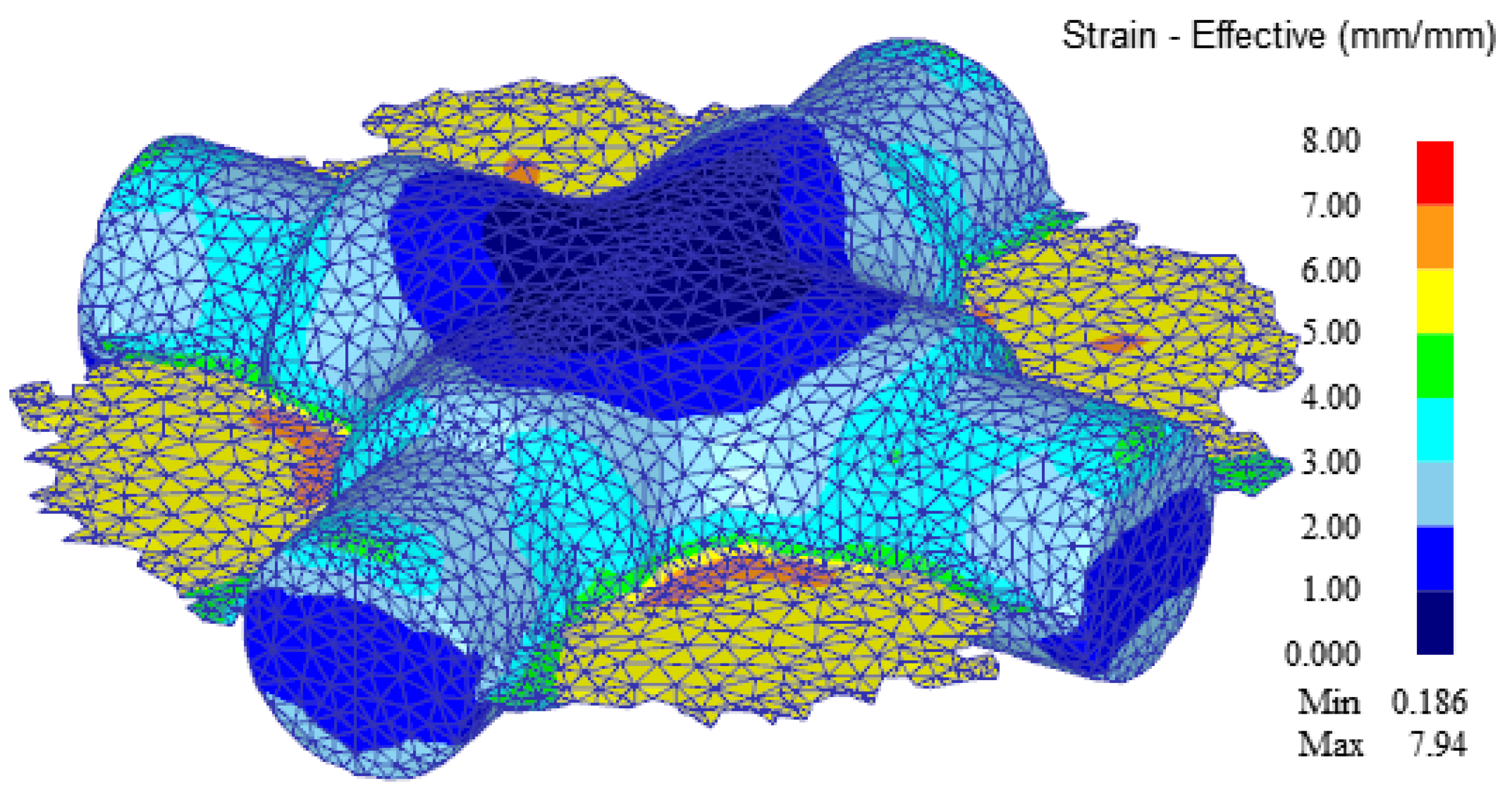
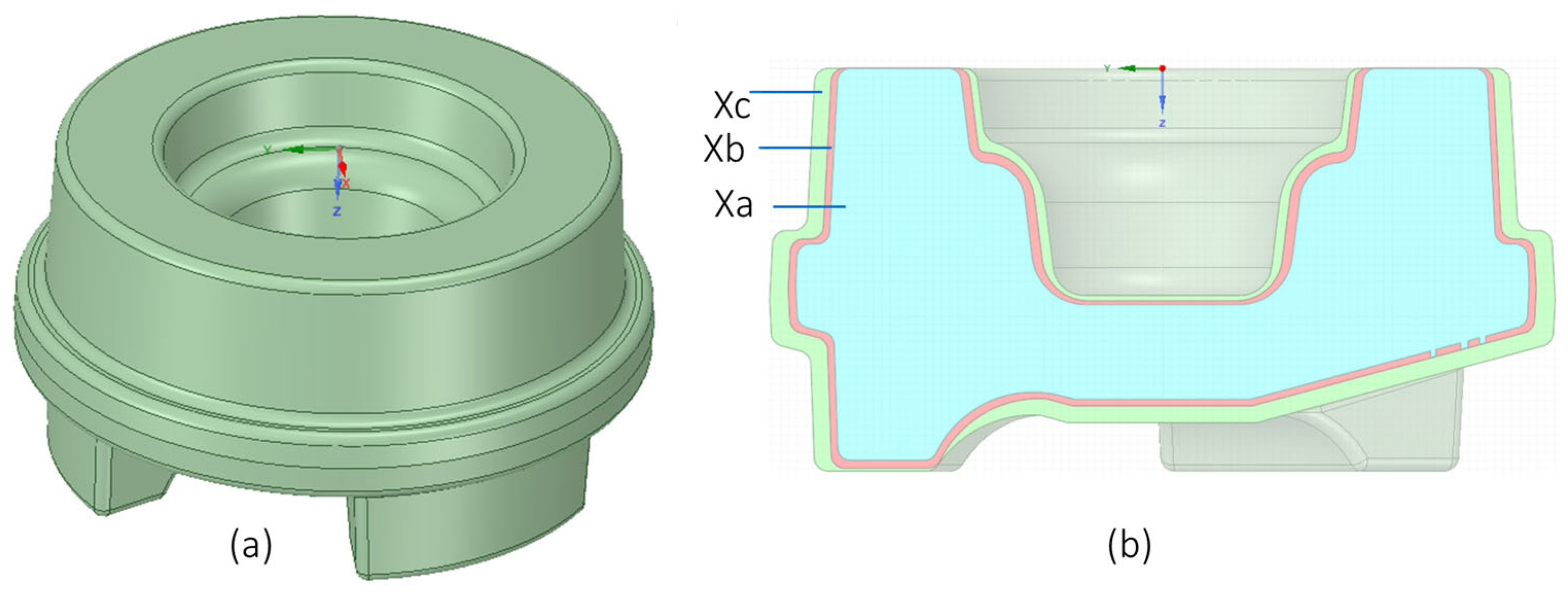
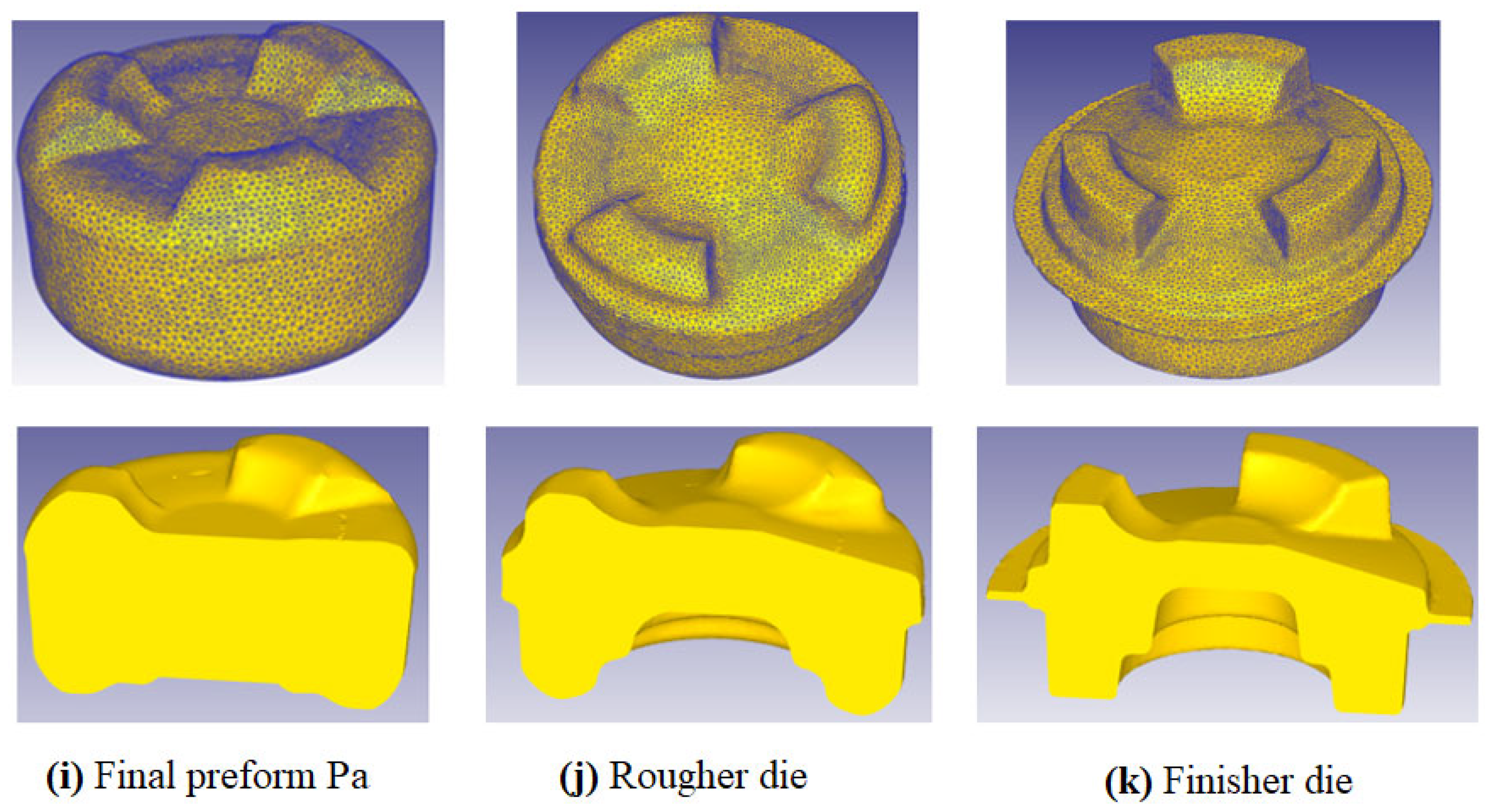
3.2. Three-Lobe Drive Hub Forging
4. Experimental Validation
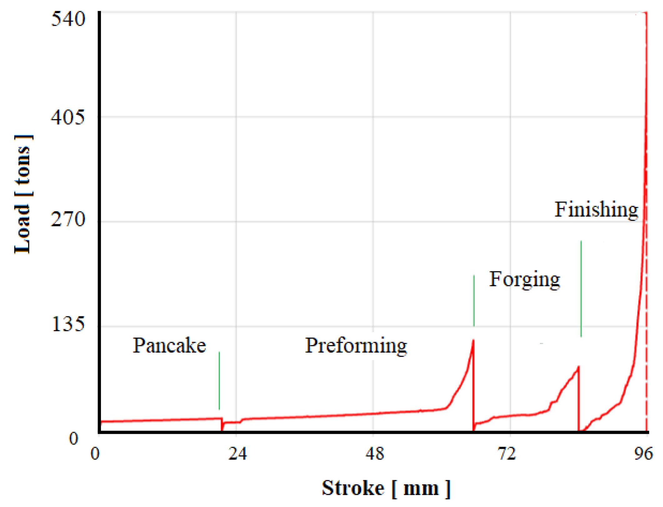
4.1. Preliminary FE Forging Simulations
4.2. Laboratory-Scale Forging Tests
4.2.1. Test Setup Design
4.2.2. Test Procedures
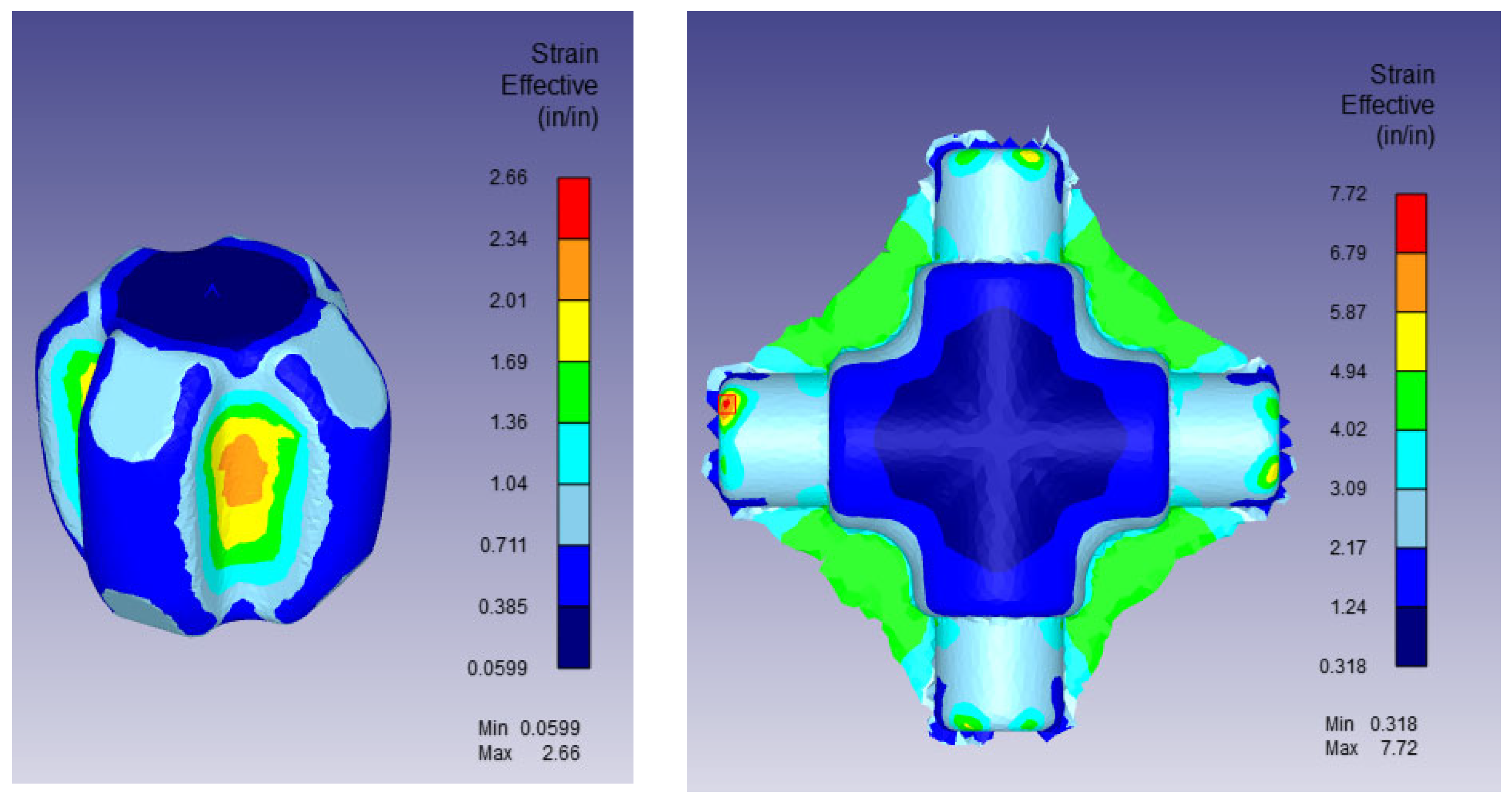
4.2.3. Test Results and Discussions
5. Discussion on Viability, Limitations, and Prospects of the Proposed Method
6. Conclusions and Future Work
- Preform search for complex 3D forgings requires careful handling of point cloud data. Unlike 2D forging problems, finding an optimal preform for complex geometries demands a more refined mesh to capture sufficient data points. However, since extremely fine meshes are often impractical, geometry smoothing techniques must be adopted, which may result in the loss of some minor geometric details on the determined preform.
- The cross-joint case study demonstrated material savings of approximately 13.5% through the introduction of an intermediate preform stage developed using the proposed scheme.
- Substantial material waste reduction is attainable even in highly complex 3D forging scenarios, as evidenced by the three-lobe drive hub case study, where iterative refinement of the preform during FE simulation significantly minimized flash formation.
- While data handling remains a potential challenge, advances in computational speed and the integration of DOE and optimization techniques into metal forming software have greatly reduced these concerns. The methodology is thus becoming increasingly practical for industrial applications.
- Conducting a sensitivity analysis on the influence of different initial expanded geometries to quantify their impact on the convergence behavior and accuracy of the final preform obtained through the iterative backtracking and optimization process.
- Automating key steps in the workflow, particularly point generation, surface smoothing, and solid geometry reconstruction from point cloud data, by implementing advanced algorithms and automation tools.
- Developing a hybrid workflow that combines FEA-based material point backtracking with DOE and surrogate modeling techniques. In this approach, the backtracked preform would serve as a physically accurate initial design, which would then be refined through parametric optimization strategies such as Response Surface Methodology or Kriging models. This hybrid method would accelerate convergence toward flashless, fully filled forgings while maintaining manufacturability.
- By addressing these areas, the proposed methodology can evolve into a powerful and practical tool for forging preform design across a wide range of industrial applications.
Author Contributions
Funding
Data Availability Statement
Acknowledgments
Conflicts of Interest
References
- Vemuri, K.R.; Oh, S.I.; Altan, T. A Knowledge-Based System to Automate Blocker Design. Int. J. Mach. Tools Manuf. 1989, 29, 505–518. [Google Scholar] [CrossRef]
- Kim, H.; Taylan, A. Computer-aided Part and Processing-Sequence Design in Cold Forging. J. Mater. Process. Technol. 1992, 33, 57–74. [Google Scholar] [CrossRef]
- Caporalli, A.; Gileno, L.A.; Button, S.T. Expert System for Hot Forging Design. J. Mater. Process. Technol. 1998, 80–81, 131–135. [Google Scholar] [CrossRef]
- Osakada, K.; Yang, G.B.; Nakamura, T.; Mori, K. Expert System for Cold-Forging Process Based on FEM Simulation. CIRP Ann. 1990, 39, 249–252. [Google Scholar] [CrossRef]
- Bariani, P.; Knight, W.A. Computer-Aided Cold Forging Process Design: A Knowledge-Based System Approach to Forming. CIRP Ann. 1988, 37, 243–246. [Google Scholar] [CrossRef]
- Kim, D.Y.; Park, J.-J. Development of an Expert System for the Process Design of Axisymmetric Hot Steel Forging. J. Mater. Process. Technol. 2000, 101, 223–230. [Google Scholar] [CrossRef]
- Kim, H.-S.; Im, Y.-T. Expert System for Multi-Stage Cold-Forging Process Design with a Re-Designing Algorithm. J. Mater. Process. Technol. 1995, 54, 271–285. [Google Scholar] [CrossRef]
- Matsunaga, K.; Umeda, M.; Mure, Y.; Katamine, K. Knowledge-Based Design Method of Forging Dies Based on the Stereotypes of Die Structures and the Functions of Forming Surfaces. Procedia Manuf. 2020, 50, 475–482. [Google Scholar] [CrossRef]
- Umeda, M.; Mure, Y.; Katamine, K.; Kawahigashi, K. General Step Reduction Method for Knowledge-Based Process Planning of Non-Axisymmetrical Forged Products. Procedia Eng. 2017, 207, 448–453. [Google Scholar] [CrossRef]
- Hedicke-Claus, Y.; Kriwall, M.; Stonis, M.; Behrens, B.A. Automated design of multi-stage forging sequences for die forging. Prod. Eng. 2023, 17, 689–701. [Google Scholar] [CrossRef]
- Park, J.J.; Rebelo, N.; Kobayashi, S. A new approach to preform design in metal forming with the finite element method. Int. J. Mach. Tool Des. Res. 1983, 23, 71–79. [Google Scholar] [CrossRef]
- Zhao, G.; Wright, E.; Grandhi, R.V. Computer aided design in forging using the inverse die contact tracking method. Int. J. Mach. Tools Manuf. 1996, 36, 755–769. [Google Scholar] [CrossRef]
- Chang, C.C.; Bramley, A.N. Forging preform design using reverse simulation approach with the upper bound finite element procedure. Proc. Inst. Mech. Eng. Part C J. Mech. Eng. Sci. 2000, 214, 127–136. [Google Scholar] [CrossRef]
- Lorenzo, R.; Micari, F. An Inverse Approach for the Design of the Optimal Preform Shape in Cold Forging. CIRP Ann. 1998, 47, 7. [Google Scholar] [CrossRef]
- Park, J.J.; Hwang, H.S. Preform Design for Precision Forging of an Asymmetric Rib-Web Type Component. J. Mater. Process. Technol. 2007, 187–188, 595–599. [Google Scholar] [CrossRef]
- Sedighi, M.; Tokmechi, S. A New Approach to Preform Design in Forging Process of Complex Parts. J. Mater. Process. Technol. 2008, 197, 314–324. [Google Scholar] [CrossRef]
- Yang, C.; Ngaile, G. Preform design for forging and extrusion processes bases on geometric resemblance. Proc. Inst. Mech. Eng. Part B J. Eng. Manuf. 2010, 224, 1409–1423. [Google Scholar] [CrossRef]
- Santangelo, A.; Blanke, P.; Hadifi, T.; Wolter, F.E.; Behrens, B.-A. Fast 3D inverse simulation of hot forging processes via Medial Axis Transformation: An approach for preform estimation in hot die forging. Prod. Eng. Res. Devel. 2013, 7, 409–416. [Google Scholar] [CrossRef]
- Meyer, M.; Stonis, M.; Behrens, B.-A. Cross wedge rolling and bi-directional forging of preforms for crankshafts. Prod. Eng. Res. Devel. 2015, 9, 61–71. [Google Scholar] [CrossRef]
- Knust, J.; Stonis, M.; Behrens, B.-A. Preform Optimization for Hot Forging Processes Using an Adaptive Amount of Flash Based on the Cross-Section Shape Complexity. Ger. Acad. Soc. Prod. Eng. 2016, 10, 587–598. [Google Scholar] [CrossRef]
- Lee, S.R.; Lee, Y.K.; Park, C.H.; Yang, D.Y. A new method of preform design in hot forging by using electric field theory. Int. J. Mech. Sci. 2002, 44, 773–792. [Google Scholar] [CrossRef]
- Cai, J.; Li, F.; Liu, T. A new approach of preform design based on 3D electrostatic field simulation and geometric transformation. Int. J. Adv. Manuf. Technol. 2011, 56, 579–588. [Google Scholar] [CrossRef]
- Guan, Y.; Bai, X.; Liu, M.; Song, L.; Zhao, G. Preform design in forging process of complex parts by using quasi-equipotential field and response surface methods. Int. J. Adv. Manuf. Technol. 2015, 79, 21–29. [Google Scholar] [CrossRef]
- Biba, N.; Vlasov, A.; Krivenko, D.; Duzhev, A.; Stebunov, S. Closed Die Forging Preform Shape Design Using Isothermal Surfaces Method. Procedia Manuf. 2020, 47, 268–273. [Google Scholar] [CrossRef]
- Kim, K.; Han, B.; Kim, Y.; Kim, N. Detailed Preform Design Procedure Considering the Effect of Heat Treatment in IN718 Disk Forging. J. Mater. Res. Technol. 2024, 30, 4625–4644. [Google Scholar] [CrossRef]
- Park, D.; Park, J.; Kim, N. A 3D Preform Design Method Based on a Generative Artificial Intelligence Algorithm. J. Manuf. Process. 2025, 144, 190–208. [Google Scholar] [CrossRef]
- Shao, Y.; Lu, B.; Xu, D.K.; Chen, J.; Ou, H.; Long, H.; Guo, P.Y. Topology-based preform design optimization for blade forging. Int. J. Adv. Manuf. Technol. 2016, 86, 1593–1605. [Google Scholar] [CrossRef]
- Torabi, S.H.R.; Alibabaei, S.; Bonab, B.B.; Sadeghi, M.H.; Faraji, G.h. Design and optimization of turbine blade preform forging using RSM and NSGA II. J. Intell. Manuf. 2017, 28, 1409–1419. [Google Scholar] [CrossRef]
- Saquib, A.N.; Khaleed, H.M.T.; Badruddin, I.A.; Algahtani, A.; Addas, M.F.; Abdullah, A.B.; Athani, A.; Kamangar, S.; Khan, T.M. Development of Preform for Simulation of Cold Forging Process of a V8 Engine Camshaft Free from Flash & Under-Filling. Mathematics 2019, 7, 1026. [Google Scholar] [CrossRef]
- Shao, Y.; Yan, L.; Guo, P.; Yang, H.; Shi, F.; Feng, D. A Comprehensive Study on Fitness Approximation Techniques in Shape Optimization of Aerofoil Forging Preform Tools. Metals 2019, 9, 617. [Google Scholar] [CrossRef]
- Lee, S.; Quagliato, L.; Park, D.; Kwon, I.; Sun, J.; Kim, N. A New Approach to Preform Design in Metal Forging Processes Based on the Convolution Neural Network. Appl. Sci. 2021, 11, 7948. [Google Scholar] [CrossRef]
- Oh, M.; Oh, M.; Kim, J.; Cho, J.; Kim, M.; Joun, M.; Hong, S. Reliability-Based Design Optimization of Bearing Hub Preform for Minimizing Defects Considering Manufacturing Tolerance in Hot Forging Process. Appl. Sci. 2024, 14, 11316. [Google Scholar] [CrossRef]


| Group | Category | Typical Techniques | Stage Focus | Strengths | Limitations | Interaction with Other Groups |
|---|---|---|---|---|---|---|
| Group 1 | Multi-stage sequence generation |
| More than two stages | Fast sequence generation; early-stage planning | Accuracy is limited without physics-based refinement | Provides initial multi-stage plans to Groups 2 and 3 |
| Group 2 | Two-stage preform design |
| Two-stage processes. Axisymmetric and plane strain | Physics-based design; near-net-shape preforms | Challenging for complex 3D parts; needs accurate deformation data | Can operate independently or feed into Group 3 for fine-tuning |
| Group 3 | Optimization and refinement |
| Any stage (as a post-process) | Fine-tunes geometry; improves manufacturability | Requires an initial shape and can be computationally expensive | Refines designs from Groups 1 and 2 for final deployment |
| Parameter | Value/Description |
|---|---|
| Material Model | AISI 1016 (sourced from DEFORM Material Library) |
| Billet Temperature | 1000 °C |
| Die Temperature | 250 °C |
| Interface Friction Model | Shear friction law (friction factor m = 0.3) |
| Parameter | Value/Description |
|---|---|
| Material Model | AISI 1035 (sourced from DEFORM Material Library |
| Billet Temperature | 1200 °C |
| Die Temperature | 150 °C |
| Interface Friction Model | Shear friction law (friction factor m = 0.3) |
| Parameter | Value/Description |
|---|---|
| Material Model | AL6061 (sourced from DEFORM Material Library) |
| Billet Temperature | 400 °C |
| Die Temperature | 150 °C |
| Interface Friction Model | Shear friction law (friction factor m = 0.3) |
| Billet transfer | 15 s set for billet heat loss (air heat transfer) |
Disclaimer/Publisher’s Note: The statements, opinions and data contained in all publications are solely those of the individual author(s) and contributor(s) and not of MDPI and/or the editor(s). MDPI and/or the editor(s) disclaim responsibility for any injury to people or property resulting from any ideas, methods, instructions or products referred to in the content. |
© 2025 by the authors. Licensee MDPI, Basel, Switzerland. This article is an open access article distributed under the terms and conditions of the Creative Commons Attribution (CC BY) license (https://creativecommons.org/licenses/by/4.0/).
Share and Cite
Ngaile, G.; Kumaran, K. Physics-Informed Preform Design for Flashless 3D Forging via Material Point Backtracking and Finite Element Simulations. J. Manuf. Mater. Process. 2025, 9, 202. https://doi.org/10.3390/jmmp9060202
Ngaile G, Kumaran K. Physics-Informed Preform Design for Flashless 3D Forging via Material Point Backtracking and Finite Element Simulations. Journal of Manufacturing and Materials Processing. 2025; 9(6):202. https://doi.org/10.3390/jmmp9060202
Chicago/Turabian StyleNgaile, Gracious, and Karthikeyan Kumaran. 2025. "Physics-Informed Preform Design for Flashless 3D Forging via Material Point Backtracking and Finite Element Simulations" Journal of Manufacturing and Materials Processing 9, no. 6: 202. https://doi.org/10.3390/jmmp9060202
APA StyleNgaile, G., & Kumaran, K. (2025). Physics-Informed Preform Design for Flashless 3D Forging via Material Point Backtracking and Finite Element Simulations. Journal of Manufacturing and Materials Processing, 9(6), 202. https://doi.org/10.3390/jmmp9060202