
Development of Deep Drawing Processes Under Indirect Hot Stamping Method for an Automotive Internal Combustion Engine Oil Pan Made from Ultra-High-Strength Steel (UHSS) Sheets Using Finite Element Simulation with Experimental Validation

Abstract

1. Introduction
2. Materials for Generating the Oil Pan and Materials Model
2.1. Boron Steel Grade 22MnB5
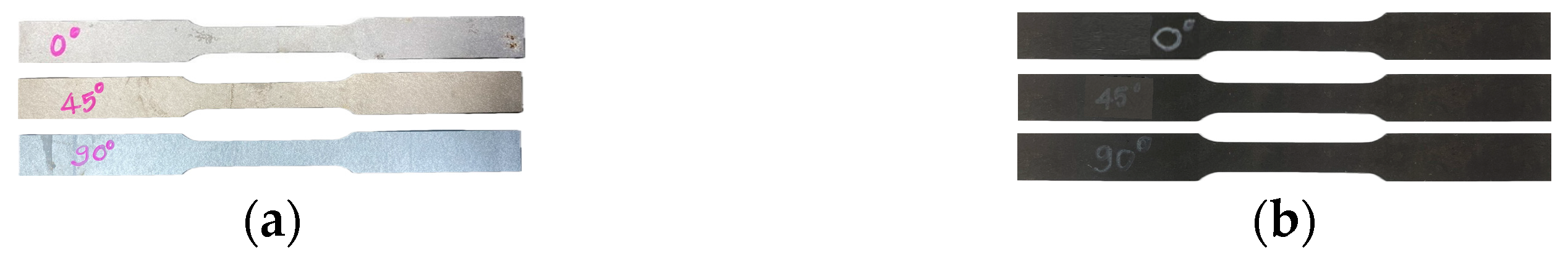
2.2. Uniaxial Tensile Test
2.3. Materials Model
2.3.1. The Cold-Stamping Materials Model
Yield Criterion
Hardening Law
Forming Limit Curves
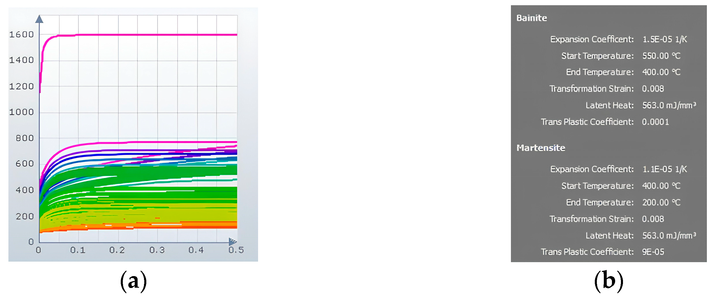
2.3.2. Material Modeling and Advanced Options in AutoForm R8 for Indirect Hot Stamping Method
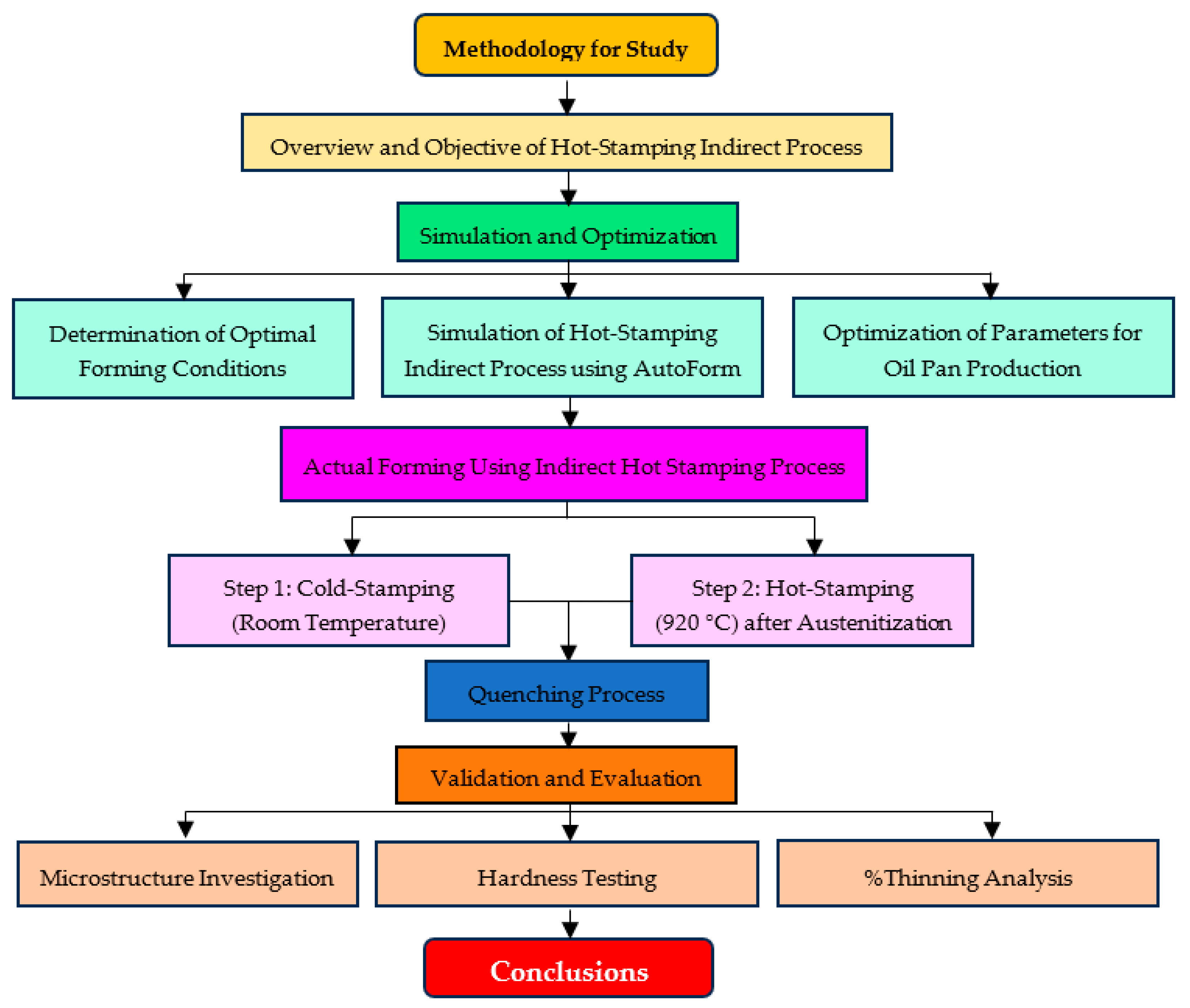
3. Methodology
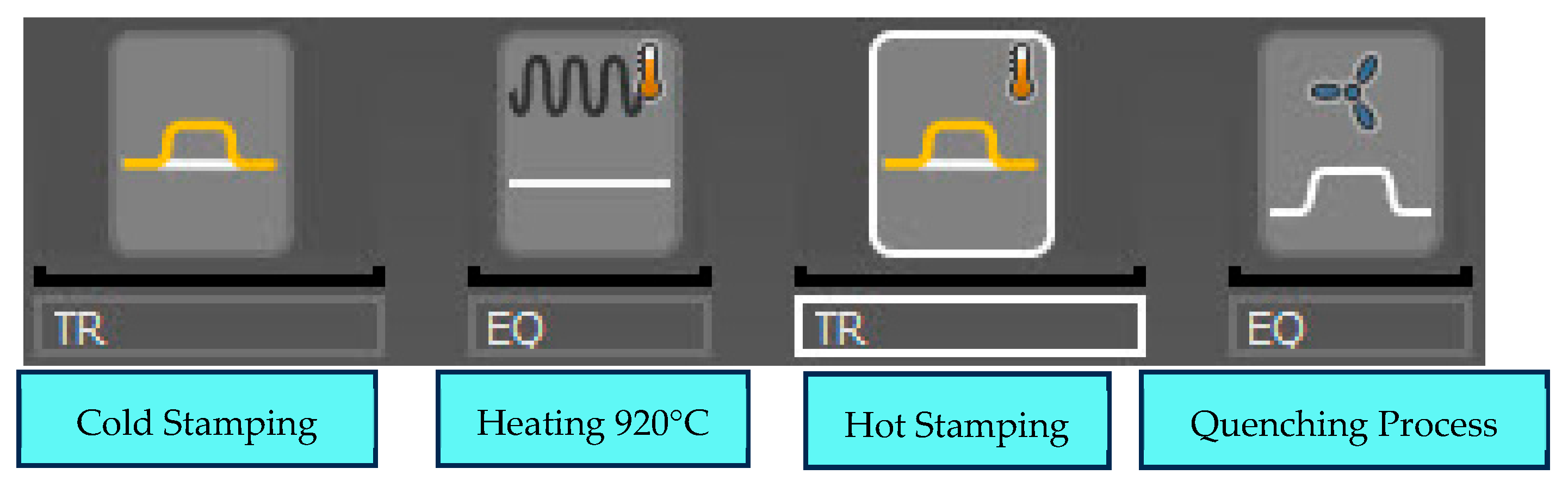
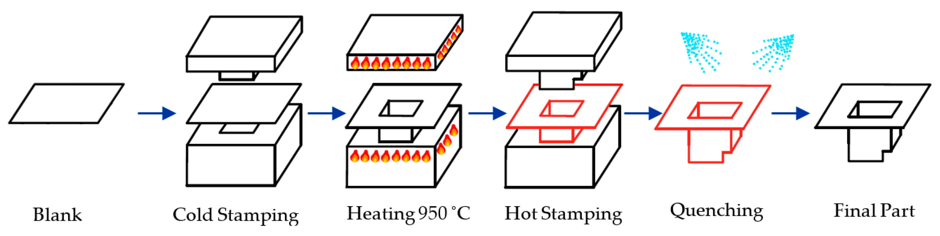
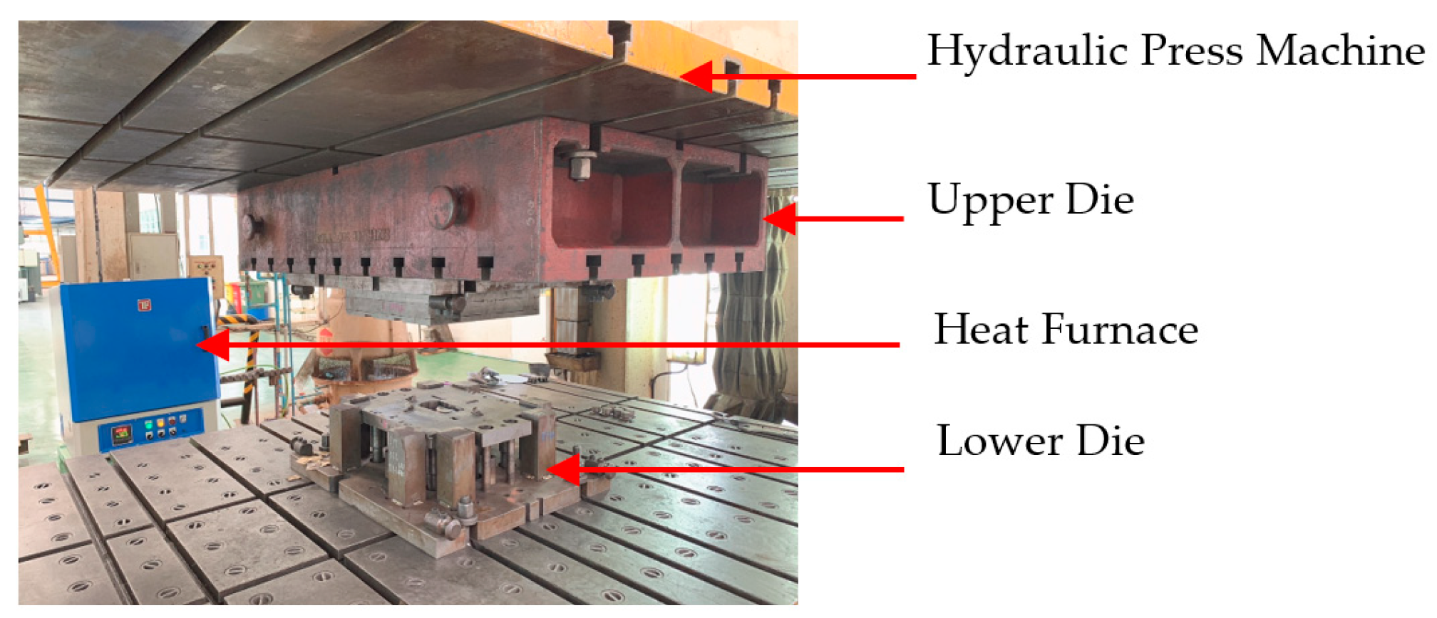
3.1. Indirect Hot Stamping Method
3.1.1. First Step of Indirect Hot Stamping Method by Cold Stamping at Room Temperature
3.1.2. Second Step of Indirect Process for Generating the Oil Pan by Hot Stamping at 920 Celsius
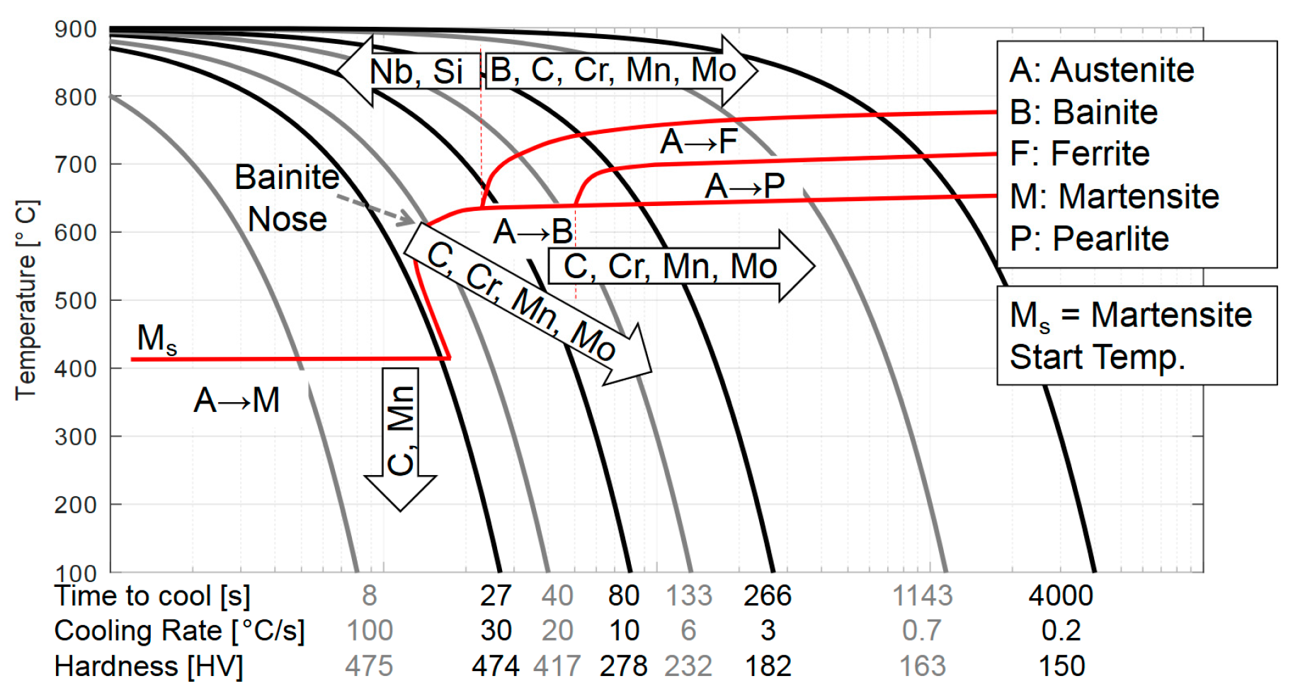
3.1.3. Quenching Process After Indirect Hot Stamping Method
3.2. Determination of Optimal Conditions for Automotive Component Formation via Indirect Hot Stamping Method
3.2.1. Find the Optimal Initial Blank Size for Generating the Oil Pan
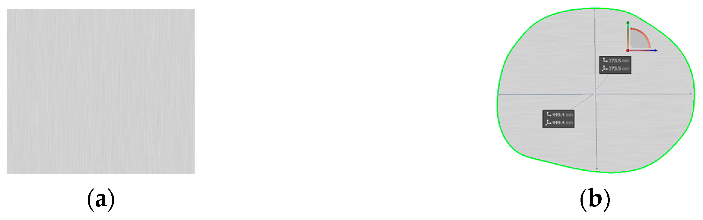
- The Shape of Initial Blank Size
- 2.
- Dimension of the Initial Blank Size
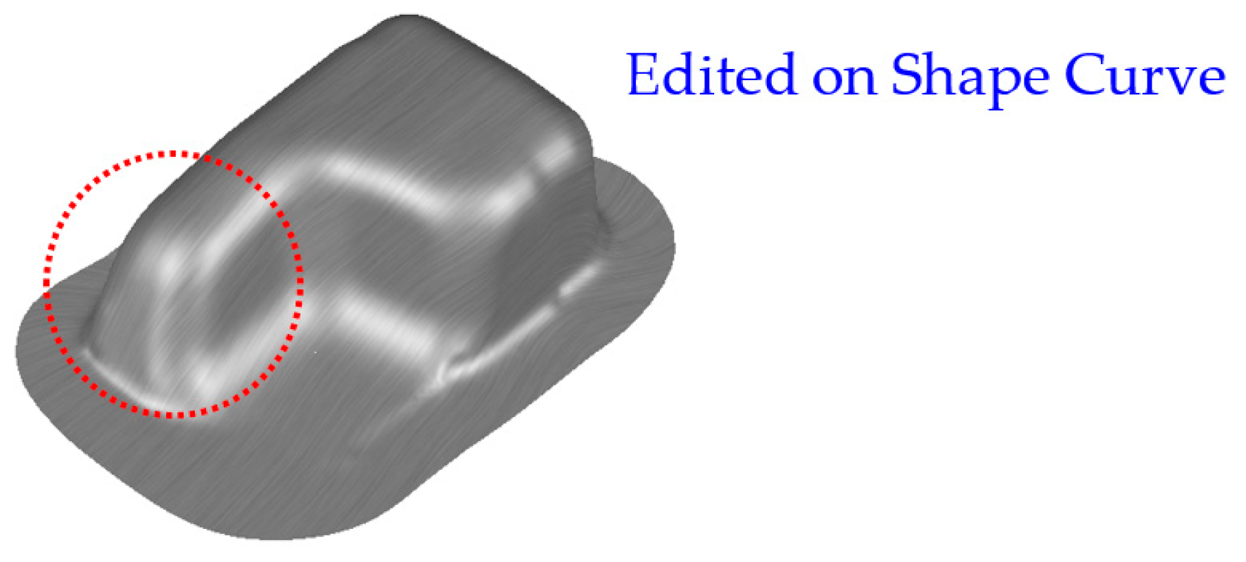
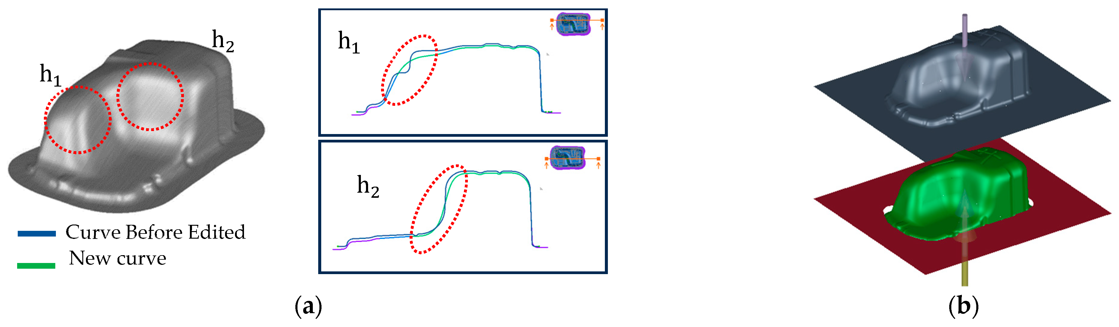
3.2.2. Find the Optimal Die Shape for Generating the Oil Pan
- Determine Optimal Die Shape for Initial Indirect Hot Stamping Step
- 2.
- Determine Optimal Die Shape for Second Indirect Hot Stamping Step
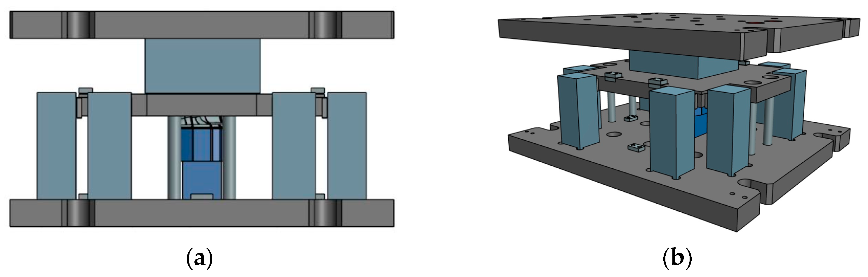
3.3. Generate Oil Pan Die from AutoForm Simulation
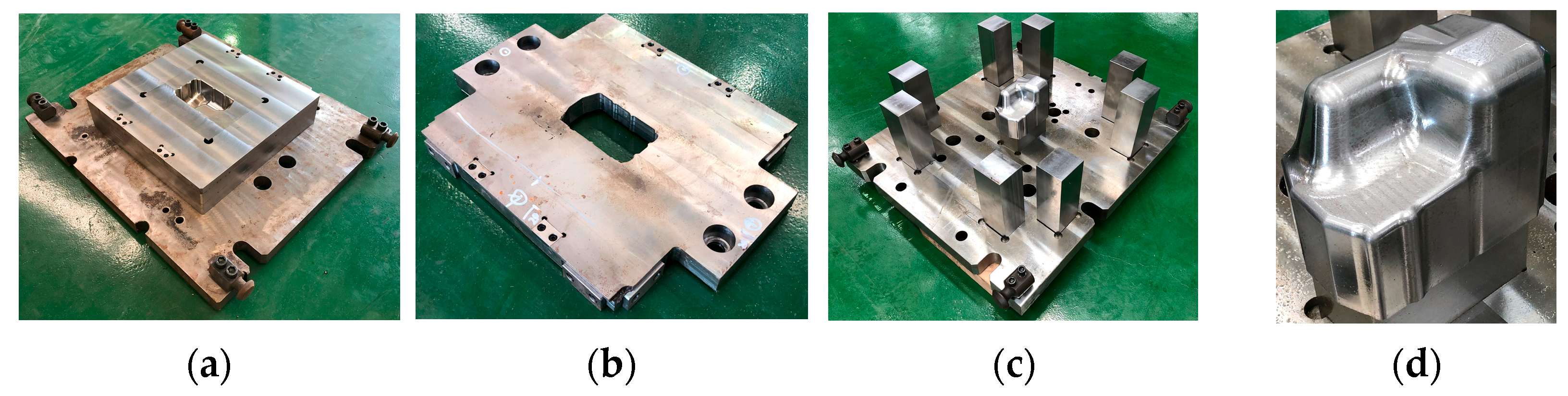
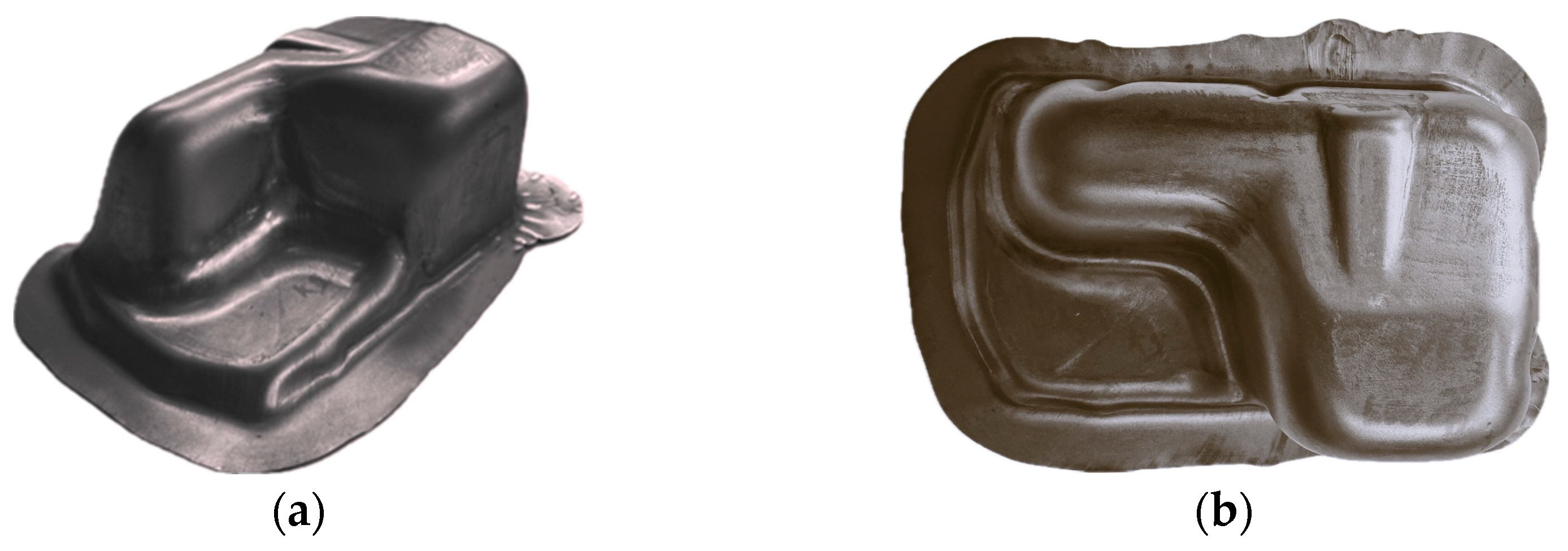
3.4. Generate Oil Pan Based on AutoForm Simulation Conditions Using Indirect Hot Stamping Method
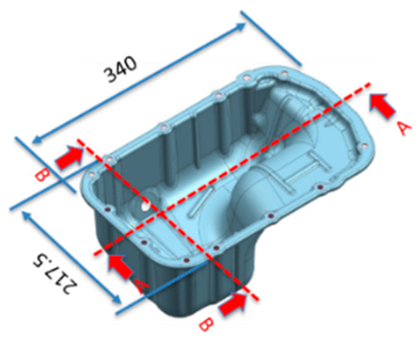
3.5. Investigate Oil Pan Characterization and Percent Thinning After Indirect Hot Stamping Method
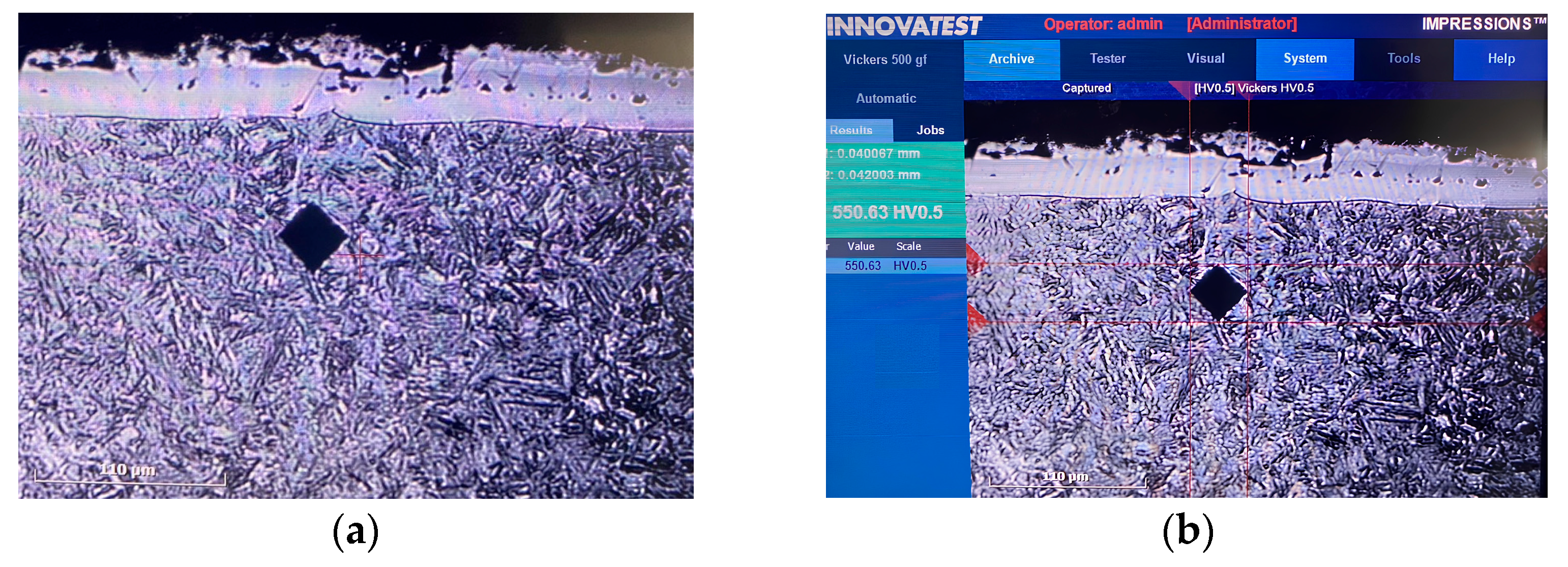
3.5.1. Oil Pan Microstructure After Indirect Hot Stamping Method
3.5.2. Oil Pan Hardness After Indirect Hot Stamping Method
3.5.3. Oil Pan Percent Thinning After Indirect Hot Stamping Method
4. Results of Indirect Hot Stamping Process
4.1. Results of Optimal Conditions for Automotive Component Formation Using Indirect Hot Stamping Method
4.1.1. The Best Initial Blank Size for Generated the Oil Pan
- The Shape of Initial Blank Size
- 2.
- Dimension of the Initial Blank Size
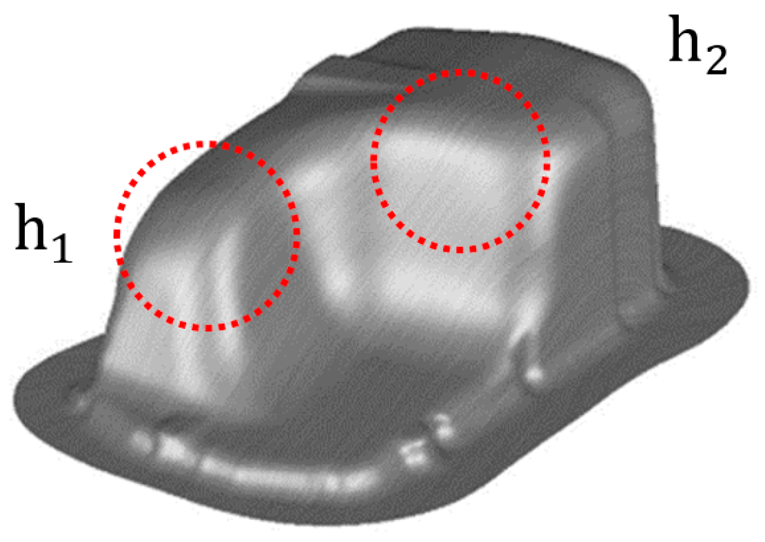
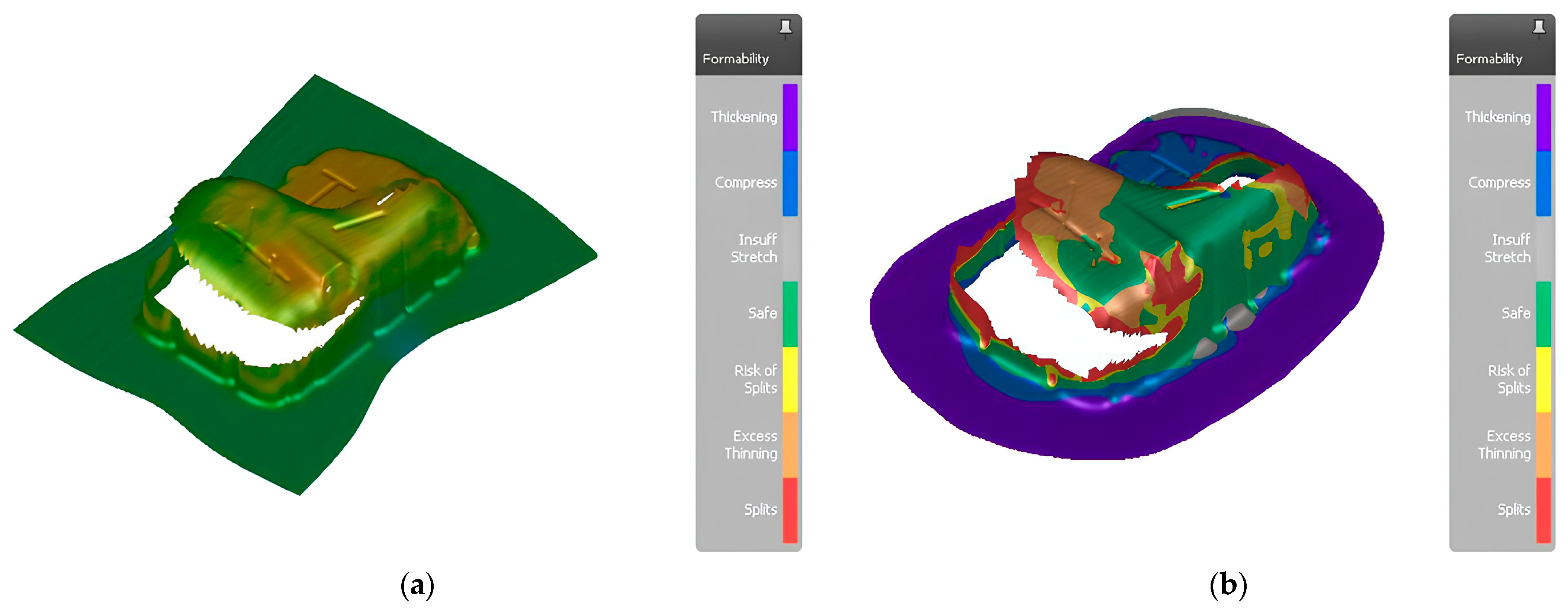
4.1.2. Optimal Die Shape for Generating Oil Pan
- Find Optimal Die Shape for First Step of Indirect Hot Stamping Process
- 2.
- Find Optimal Die Shape for Second Step of Indirect Hot Stamping Process
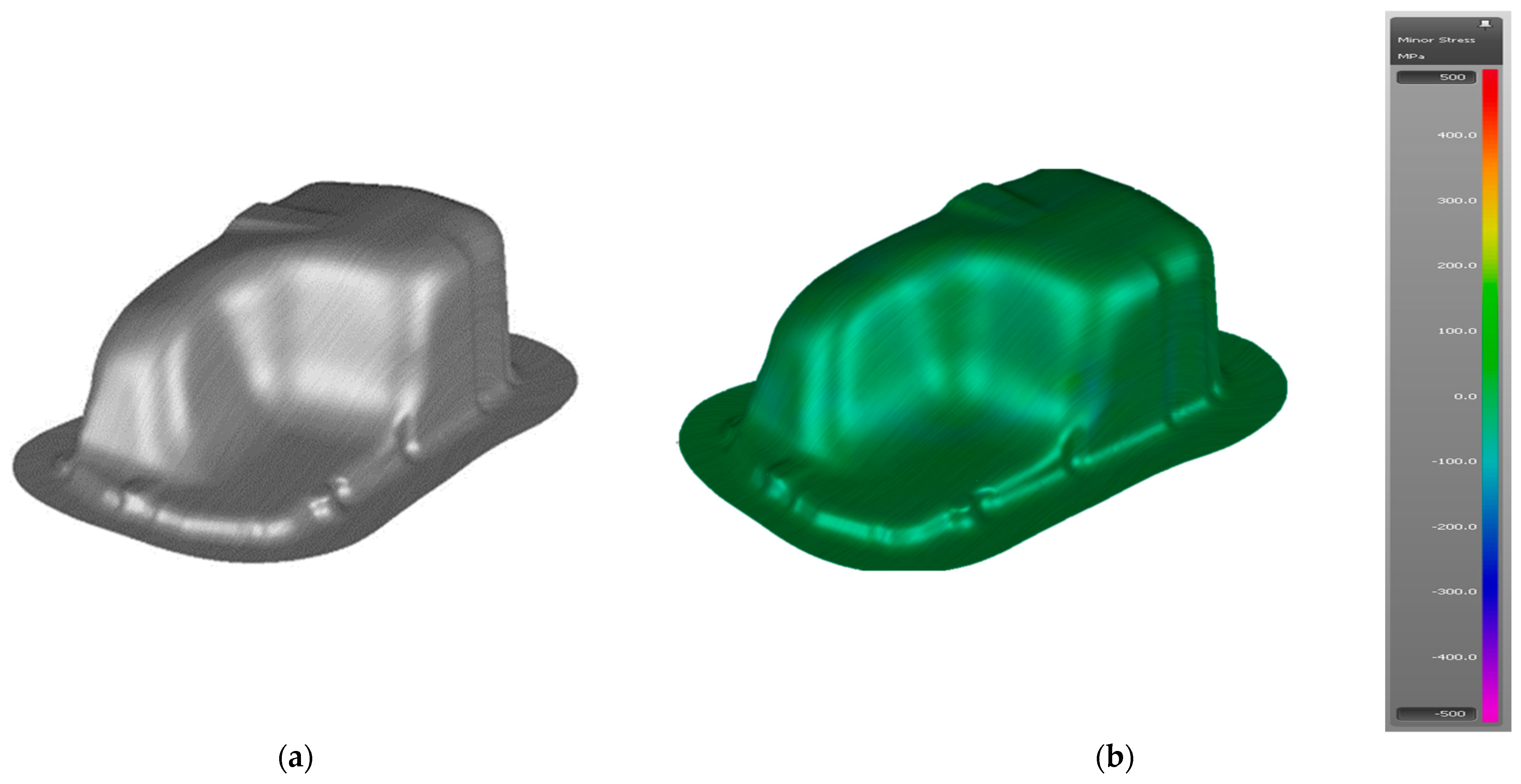
4.2. Results Die of Oil Pan from Simulation in AutoForm Program
4.3. Generate Oil Pan Based on AutoForm Simulation Conditions Using Indirect Hot Stamping Method
4.4. Investigate Oil Pan Characterization and Percent Thinning After Indirect Hot Stamping Method
4.4.1. Microstructure of Oil Pan After Indirect Hot Stamping Method
4.4.2. Hardness of Oil Pan After Indirect Hot Stamping Method
4.4.3. Oil Pan Percent Thinning After Indirect Hot Stamping Method
5. Conclusions
Author Contributions
Funding
Data Availability Statement
Acknowledgments
Conflicts of Interest
References
- Billur, E. Hot Stamping of Ultra High-Strength Steels; Springer: New York, NY, USA, 2018; ISBN 978-3-319-98868-9. [Google Scholar]
- Thai Parkerizing Co., Ltd. Available online: https://www.thaiparker.co.th/en/articles/processing-service/automotive-manufacturing-process (accessed on 15 August 2024).
- Ünsal, I.; Hirtler, M.; Sviridov, A.; Bambach, M.; Hama-Saleh, R.; Weisheit, A.; Schleifenbaum, J.H.; Kamaliev, M.; Tekkaya, A.E. Investigation of Martensite-Transformation and Forming Properties of Additively Reinforced 22MnB5 Sheet Metals. AIP Conf. Proc. 2019, 2113, 170019. [Google Scholar] [CrossRef]
- He, L.-f.; Zhao, G.-q.; Li, H.-p.; Xiang, N. Research on Mechanical Properties of 22MnB5 Steel Quenched in a Steel Die. J. Shanghai Jiaotong Univ. Sci. 2011, 16, 129–132. [Google Scholar] [CrossRef]
- Zeng, J.; Yang, R.; Hao, L.; Wang, W.; Zhu, C. Evolution of the Microstructure and Mechanical Properties of As-Cast 22MnB5 Hot-Stamping Steel Processed by a Novel Sub-rapid Solidification Technique. Metall. Mater. Trans. B 2023, 55, 512–523. [Google Scholar] [CrossRef]
- Singh, A.K.; Narasimhan, K.; Narkhede, S.S.; Sarawagi, V. Formability Studies on 22MnB5 Steel During Hot Stamping Conditions. In Proceedings of the IDDRG—2018 Conference, Waterloo, ON, Canada, 3–7 June 2018. [Google Scholar]
- Paćko, M.; Krawczyk, J.; Śleboda, T.; Frocisz, T. State of Strain and Development of Microstructure of 22MnB5 Steel and Al-Si Coating During Deep Drawing of Automotive B Pillar. Arch. Metall. Mater. 2021, 66, 931–940. [Google Scholar] [CrossRef]
- Skowronek, A.; Wróbel, I.; Grajcar, A. Design, Simulation and Experimental Evaluation of Hot-Stamped 22MnB5 Steel Autobody Part. Symmetry 2022, 14, 2625. [Google Scholar] [CrossRef]
- Bang, J.; Kim, M.; Bae, G.; Song, J.; Kim, H.G.; Lee, M.G. Quantitative Evaluation of Tool Wear in Cold Stamping of Ultra-High-Strength Steel Sheets. Metals Mater. Int. 2023, 29, 327–342. [Google Scholar] [CrossRef]
- Berahmani, S.; Bruinekreeft, L.; Güner, A.; Venema, J.; Sigvant, M. An Industrial Application Case to Predict Galling in Hot Stamping Processes. IOP Conf. Ser. Mater. Sci. Eng. 2022, 1238, 012061. [Google Scholar] [CrossRef]
- Leelaseat, J.; Sunanta, A.; Suranuntchai, S. Formability assessment based on Q-value for optimizing the deep drawing process of automotive parts made from aluminum alloys sheet. Metals 2025, 15, 68. [Google Scholar] [CrossRef]
- AutoForm. Hot Forming. Available online: https://www.autoform.com/en/topics/technologies/hot-forming/ (accessed on 28 March 2025).
- Palmieri, M.E.; Galetta, F.R.; Tricarico, L. Study of Tailored Hot Stamping Process on Advanced High-Strength Steels. J. Manuf. Mater. Process. 2022, 6, 11. [Google Scholar] [CrossRef]
- Ying, L.; Gao, T.; Dai, M.; Yang, Y.; Hu, P. Experimental Investigation of Temperature-Dependent Interfacial Heat Transfer Mechanism with Spray Quenching for 22MnB5 Steel. Appl. Therm. Eng. 2017, 121, 48–66. [Google Scholar] [CrossRef]
- Thanaunyaporn, Y.; Charoensuk, J.; Larprasoetkun, P.; Suranuntchai, S. Development of the internal combustion engine oil pan in deep drawing process: FE simulation and experimental validation. J. Eng. Sci. Technol. 2025, 20, 590–611. [Google Scholar]
- Jeon, Y.J.; Song, M.J.; Kim, H.K.; Cha, B.S. Effect of hot-stamping process conditions on the changes in material strength. Int. J. Automot. Technol. 2015, 16, 619–627. [Google Scholar] [CrossRef]
- AutoForm. AutoForm R8: Streamlined Digital Process Chain. Available online: https://www.autoform.com/en/autoform-r8-streamlined-digital-process-chain/ (accessed on 28 March 2025).
- Zhang, H.; Wei, W.; Long, S.; Zhou, M.; Li, C. Optimization of Stamping Process Parameters for Sustainable Manufacturing: Numerical Simulation Based on AutoForm. Sustainability 2025, 17, 341. [Google Scholar] [CrossRef]
- Barlat, F.; Lian, J. Plastic behaviour and stretchability of sheet metals. Part I: A yield function for orthotropic sheets under plane stress conditions. Int. J. Plast. 1989, 5, 51–66. [Google Scholar]
- Swift, H.W.; Mech, J. Phys of solids. J. Mech. Phys. Solids 1952, 1, 1–18. [Google Scholar] [CrossRef]
- Keeler, S.P. Determination of forming limits in automotive stampings. SAE Tech. Pap. 1965, 650535. [Google Scholar]
- Larpprasoetkun, P.; Leelaseat, J.; Nakwattanaset, A.; Suranuntchai, S. Development of forming limit diagrams for motorcycle fuel tank made from AA5754-O under deep drawing. J. Metals Mater. Miner. 2024, 34, 2013. [Google Scholar] [CrossRef]
- AutoForm. Lightweighting World 2017-06. Available online: https://www.autoform.com/fileadmin/public/Redaktion/all/newsroom/publications/2017/Lightweighting-World_2017-06.pdf (accessed on 28 March 2025).
- Liu, H.; Wei, L.; Bao, J.; Lei, C.; Xing, Z.; Song, B. Numerical and Experimental Investigation into Hot Forming of Ultra High Strength Steel Sheet. J. Mater. Eng. Perform. 2011, 20, 1–10. [Google Scholar] [CrossRef]
- ASTM E8/E8M-22; Standard Test Methods for Tension Testing of Metallic Materials. ASTM International: West Conshohocken, PA, USA, 2024.
- AHSS Insights. PHS Grades. Available online: https://ahssinsights.org/metallurgy/steel-grades/phs-grades/ (accessed on 28 March 2025).
- ASTM E131-20; Standard Test Method for Linear Thermal Expansion of Solid Materials with a Dilatometer. ASTM International: West Conshohocken, PA, USA, 2020.
- ASTM E92-17; Standard Test Method for Vickers Hardness and Knoop Hardness of Metallic Materials. ASTM International: West Conshohocken, PA, USA, 2017.
- Zhang, M.; Wan, Z.; Li, L. Transformation Characteristics and Properties of B Steel 22MnB5. Mater. Today Proc. 2015, 2 (Suppl. S3), S697–S700; [Google Scholar] [CrossRef]
- Krauss, G. Martensite in steel: Strength and structure. Mater. Sci. Eng. A 1999, 273–275, 40–57. [Google Scholar] [CrossRef]
- Morito, S.; Huang, M.X.; Furuhara, T.; Maki, T.; Hansen, B.N. The morphology and crystallography of lath martensite in Fe–C steels. Acta Mater. 2006, 54, 5323–5331. [Google Scholar] [CrossRef]
- Atkins, M. Introduction to Strain Analysis: Generating the Thinning Limit Curve from the Forming Limit Curve. Met. Form. Mag. 2021. Available online: https://www.metalformingmagazine.com/article/?/quality-control/material-testing/introduction-to-strain-analysis-generating-the-thinning-limit-curve-from-the-forming-limit-curve (accessed on 15 August 2024).


| Materials | Chemical Composition (wt.%) | |||||||
|---|---|---|---|---|---|---|---|---|
| C | Mn | B | Cr | Si | Al | Ti | N | |
| 22MnB5 | 0.220 | 1.180 | 0.002 | 0.160 | 0.220 | 0.030 | 0.040 | 0.005 |
| Mechanical Properties | Boron Steel Grade 22MnB5 | |||||
|---|---|---|---|---|---|---|
| Before Quenching | After Quenching | |||||
| Direction (Degree) | Direction (Degree) | |||||
| 0 | 45 | 90 | 0 | 45 | 90 | |
| Young’s modulus (GPa) | 180 | 192 | 180 | 195 | 219 | 204 |
| Tensile strength (MPa) | 521 | 545 | 548 | 1680 | 1683 | 1717 |
| Yield strength (MPa) | 388 | 394 | 404 | 1268 | 1190 | 1243 |
| r-values | 0.69 | 0.74 | 0.92 | 0.56 | 0.79 | 0.60 |
| n (strain hardening exponent) | 0.216 | 0.265 | 0.283 | 0.252 | 0.249 | 0.320 |
| Section | Thinning | |||||||||
|---|---|---|---|---|---|---|---|---|---|---|
| 1 | 2 | 3 | 4 | 5 | 6 | 7 | 8 | %Maximum | ||
| A | FEM | 0.182 | −0.025 | −0.052 | −0.052 | −0.057 | −0.032 | −0.034 | −0.134 | 15.17% |
| Experimental | 0.190 | −0.027 | −0.054 | −0.050 | −0.050 | −0.054 | −0.029 | −0.021 | 15.83% | |
| Customer | <20% (Maximum 0.240) | - | ||||||||
| B | FEM | 0.015 | −0.094 | −0.158 | −0.096 | −0.103 | −0.095 | −0.032 | 0.177 | 14.75% |
| Experimental | 0.020 | −0.084 | −0.150 | −0.089 | −0.154 | −0.070 | −0.041 | 0.190 | 15.83% | |
| Customer | <20% (Maximum 0.240) | - | ||||||||
| C | FEM | −0.015 | 0.010 | −0.120 | −0.216 | −0.131 | −0.097 | −0.035 | 0.192 | 18.00% |
| Experimental | −0.029 | 0.018 | −0.129 | −0.190 | −0.139 | −0.210 | −0.050 | 0.170 | 15.83% | |
| Customer | <20% (Maximum 0.240) | - | ||||||||
Disclaimer/Publisher’s Note: The statements, opinions and data contained in all publications are solely those of the individual author(s) and contributor(s) and not of MDPI and/or the editor(s). MDPI and/or the editor(s) disclaim responsibility for any injury to people or property resulting from any ideas, methods, instructions or products referred to in the content. |
© 2025 by the authors. Licensee MDPI, Basel, Switzerland. This article is an open access article distributed under the terms and conditions of the Creative Commons Attribution (CC BY) license (https://creativecommons.org/licenses/by/4.0/).
Share and Cite
Thanaunyaporn, Y.; Larpprasoetkun, P.; Nakwattanaset, A.; Hart-Rawung, T.; Suranuntchai, S. Development of Deep Drawing Processes Under Indirect Hot Stamping Method for an Automotive Internal Combustion Engine Oil Pan Made from Ultra-High-Strength Steel (UHSS) Sheets Using Finite Element Simulation with Experimental Validation. J. Manuf. Mater. Process. 2025, 9, 199. https://doi.org/10.3390/jmmp9060199
Thanaunyaporn Y, Larpprasoetkun P, Nakwattanaset A, Hart-Rawung T, Suranuntchai S. Development of Deep Drawing Processes Under Indirect Hot Stamping Method for an Automotive Internal Combustion Engine Oil Pan Made from Ultra-High-Strength Steel (UHSS) Sheets Using Finite Element Simulation with Experimental Validation. Journal of Manufacturing and Materials Processing. 2025; 9(6):199. https://doi.org/10.3390/jmmp9060199
Chicago/Turabian StyleThanaunyaporn, Yongyudth, Phiraphong Larpprasoetkun, Aeksuwat Nakwattanaset, Thawin Hart-Rawung, and Surasak Suranuntchai. 2025. "Development of Deep Drawing Processes Under Indirect Hot Stamping Method for an Automotive Internal Combustion Engine Oil Pan Made from Ultra-High-Strength Steel (UHSS) Sheets Using Finite Element Simulation with Experimental Validation" Journal of Manufacturing and Materials Processing 9, no. 6: 199. https://doi.org/10.3390/jmmp9060199
APA StyleThanaunyaporn, Y., Larpprasoetkun, P., Nakwattanaset, A., Hart-Rawung, T., & Suranuntchai, S. (2025). Development of Deep Drawing Processes Under Indirect Hot Stamping Method for an Automotive Internal Combustion Engine Oil Pan Made from Ultra-High-Strength Steel (UHSS) Sheets Using Finite Element Simulation with Experimental Validation. Journal of Manufacturing and Materials Processing, 9(6), 199. https://doi.org/10.3390/jmmp9060199