Article

Research on Robot Cleaning Path Planning of Vertical Mixing Paddle Surface

1
School of Mechanical Engineering, Northwestern Polytechnical University, Xi’an 710072, China
2
Product Design Department, AVIC Xinxiang Aviation Industry Company Limited, Xinxiang 453049, China
3
Shaanxi Dao Bo New Material Technology Co., Ltd., Xi’an 710072, China
*
Author to whom correspondence should be addressed.
J. Manuf. Mater. Process. 2025, 9(6), 198; https://doi.org/10.3390/jmmp9060198
Submission received: 6 May 2025 / Revised: 5 June 2025 / Accepted: 10 June 2025 / Published: 12 June 2025
(This article belongs to the Special Issue Advances in Robotic-Assisted Manufacturing Systems)

Abstract

The safe removal of residual flammable contaminants from vertical mixer blades is a crucial challenge in aerospace propellant production. While robotic cleaning has become the preferred solution due to its precision and operational safety, the complex helical geometry of mixer blades presents significant challenges for robotic systems, primarily in three aspects: (1) dynamic sub-region division, requiring simultaneous consideration of functional zones and residue distribution, (2) ensuring path continuity across surfaces with varying curvature, and (3) balancing time–energy efficiency in discontinuous cleaning sequences. To address these challenges, this paper proposes a novel robotic cleaning path planning method for complex curved surfaces. Firstly, we introduce a blade surface segmentation approach based on the k-means++ clustering algorithm, along with a sub-surface patch boundary determination method using parameterized curves, to achieve precise surface partitioning. Subsequently, robot cleaning paths are planned for each sub-surface according to cleaning requirements and tool constraints. Finally, with total cleaning time as the optimization objective, a genetic algorithm is employed to optimize the path combination across sub-facets. Extensive experimental results validate the effectiveness of the proposed method in robotic cleaning path planning.

1. Introduction

In the preparation process of aerospace solid motor composite propellants, residual flammable dust or chemical contaminants on the vertical mixer blades may trigger major safety accidents [1,2,3]. Robotic cleaning systems, with their high cleaning efficiency, excellent cleaning performance, and reliable safety, have gradually become core equipment for ensuring production safety [4,5].
Path planning is a critical aspect of robotic systems for achieving automation [6,7]. It determines cleaning coverage and efficiency. Furthermore, it is key to preventing explosion risks and ensuring operational safety. The blades of vertical mixers exhibit complex helical surface characteristics, which can be divided into multiple functional regions, such as the main mixing zone, transition zone, and edge zone. These regions differ significantly in residue distribution, material adhesion strength, and cleaning difficulty. To address the cleaning requirements of such irregular curved work pieces, existing research primarily adopts path planning solutions combining complex surface segmentation and sub-region operation strategies [8,9]. Specifically, the blade surface is divided into sub-regions through geometric feature segmentation, followed by customized cleaning strategies for each region.
In terms of the division of complex curved surface areas, existing research mainly focuses on segmentation methods based on geometric features or process features. Sun et al. [10] proposed a tool path planning method for the machining of complex curved surfaces. After parameterizing and projecting the complex curved surfaces, the surfaces were segmented according to the feed direction or the geometric characteristics/processing technology of the curved surfaces. In the field of complex curved surface machining, Yuan et al. [11] proposed a method for dividing the complex curved surfaces of workpieces based on the characteristics of the tool positioning surface; Bendjebla et al. [12] proposed a feature expression method for the machining of free-form surfaces based on discrete shape representation, differential geometry, and graph theory; Liu et al. [13] divided the rough machining areas according to the curvature of the curved surfaces and subdivided the complex curved surface areas based on the clustering algorithm; Sun et al. [14] partitioned the areas according to the curvature characteristics of the curved surfaces and determined the detection path of the complex curved surfaces by adjusting the distribution of sampling points in different areas. Han et al. [15], aiming at the milling problem of automobile panels, used the k-means clustering algorithm to parameterize the data of the curved surface boundary areas and decomposed the machining actions of complex curved surfaces into the combined machining of simple curved surfaces. The division of complex working surfaces can also be achieved based on the characteristics of 3D point cloud data [16,17,18,19]. By obtaining the 3D point cloud data of the curved surfaces, a characteristic function is established to complete the division of complex curved surface areas.
Sub-region path planning research focuses on parametric methods for generating surface operation paths. Li et al. [20] employed isoperimetric and constant-chord-height methods for automated robotic grinding paths on complex surfaces. Zhang et al. [21] used a distance-transform-based seed curve algorithm for laser melting path planning in additive manufacturing. Chalvin et al. [22] proposed a freeform surface contour-parallel toolpath generation algorithm, significantly improving machining efficiency. Xu et al. [23] modified standard contour paths for toolpath optimization. Holowenko et al. [24] linked machining trajectories with speed via adaptive interpolation for real-time adjustments. Bastida et al. [25] constructed a surface mesh model from 3D point cloud data and determined spraying paths through iterative algorithms. Huang et al. [26] optimized hair transplant robotic paths using ant colony algorithms with energy consumption as the objective. Jiang et al. [27] applied spline interpolation for oral restoration surface models. Hauth et al. [28] improved constant-scallop-height toolpath planning via configuration space methods. Yang et al. [29] modeled complex surface spraying path combinations as GTSP and solved them with ant colony algorithms. Wang et al. [30] optimized laser cutting idle travel using bidirectional ant colony algorithms with time minimization.
While these methods demonstrate effectiveness for various complex surfaces, they often address sub-problems in isolation (e.g., segmentation based purely on geometry, or path planning for generally defined sub-regions). Crucially, an integrated framework that simultaneously considers (1) the dynamic sub-region division based on both the inherent helical geometry and actual residue distribution specific to mixer blades, (2) generates continuous and smooth paths across these uniquely challenging helical sub-facets, and (3) optimizes the sequence of these discontinuous cleaning operations for overall efficiency in this specific application context has not been comprehensively addressed. The vertical mixer blade, with its critical role and hazardous environment, demands such a specialized solution. Therefore, an ideal robotic path planning model for vertical mixer blade cleaning must address the following challenges:
  • More reasonable sub-region division. Strategies must account for multiple factors, including the unique challenges posed by helical surfaces, as well as sub-region quantity and connectivity.
  • More accurate path planning. Strategies must overcome curvature variations on blade surfaces while improving path smoothness.
  • Higher cleaning efficiency. The model should minimize operation time and energy consumption without compromising cleaning quality.
To address these challenges, this paper introduces a novel robotic path planning method. While leveraging established algorithms, our key innovations lie in their unique integration and problem-specific adaptations for helical mixer blades, directly tackling the following issues:
  • Adaptive Segmentation for Reasonable Sub-regions: A novel hybrid process (curvature, k-means++, parametric boundaries) achieves functionally relevant divisions for complex helical surfaces.
  • Constraint-Driven Paths for Accurate Planning: Isoperimetric trajectories with parameters analytically derived from cleaning quality constraints and local geometry.
  • GTSP Sequencing for Higher Efficiency: Unique GTSP formulation for inter-sub-region travel, globally optimizing multi-stage cleaning to minimize non-productive time.
  • Validated Integrated Solution: The co-integration and physical robotic validation of these phases demonstrate a practical and effective system for cleaning vertical mixer blades.
The remainder of this paper is organized as follows: Section 2 describes the overall blade cleaning system design. Section 3 models the mixer blade. Section 4 establishes the robotic cleaning path planning model. Section 5 presents experimental results and analysis. Section 6 concludes the paper.

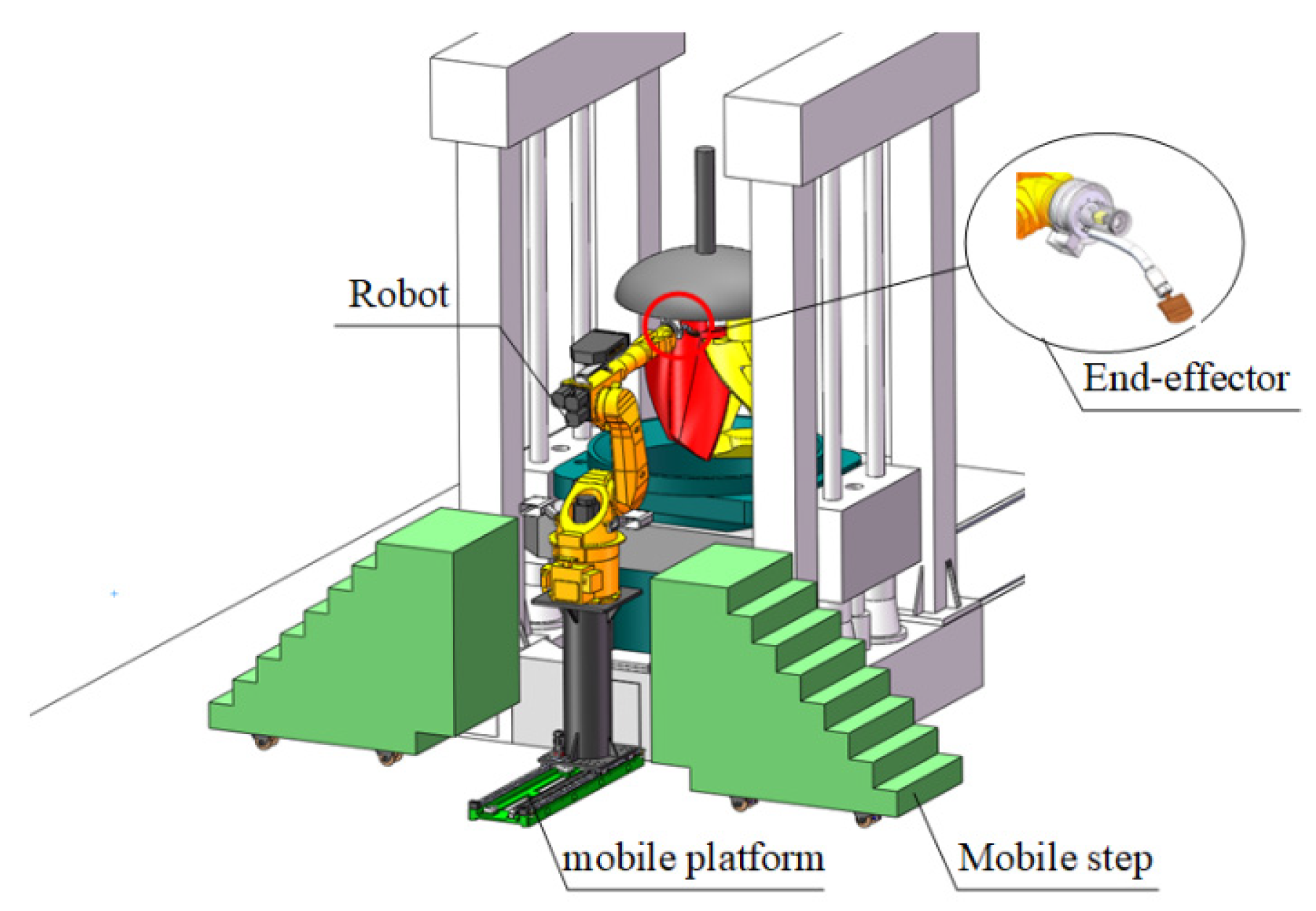
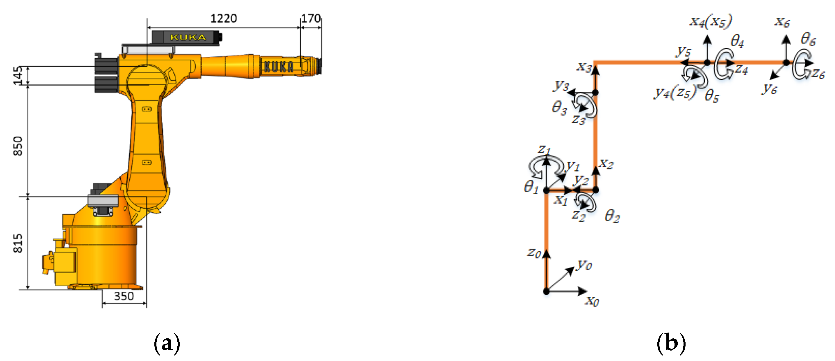
2. Robot Cleaning System of Blade Surface

The robot blade cleaning system equipment consists of a mobile platform, a six-axis industrial robot, an end-effector, and a visual inspection system. Its relative position relationship with the blade is shown in Figure 1. When mixer operation is suspended, the mobile platform transports the robot from a safe standby position to the operating position. A visual inspection system then determines the blade’s current position and posture. Subsequently, the robot cleaning process is initiated, wherein the robot maneuvers the end-effector to clean the blade. Upon completion, the mobile platform returns the robot to its safe standby position.
A Kuka KR 60L30-3 robot was selected as the six-axis industrial robot of the cleaning system, as shown in Figure 2. Figure 3 shows the shape of the cleaning system end-effector and its main geometric parameters, where L is the width of the shovel blade, R is the radius of the front arc of the shovel blade, and h is the height of the shovel blade. During the cleaning process, the front end of the shovel blade contacts with the blade surface, so the arc radius of the shovel blade front end is less than the minimum curvature radius of the blade surface ρ.

3. Mathematical Model

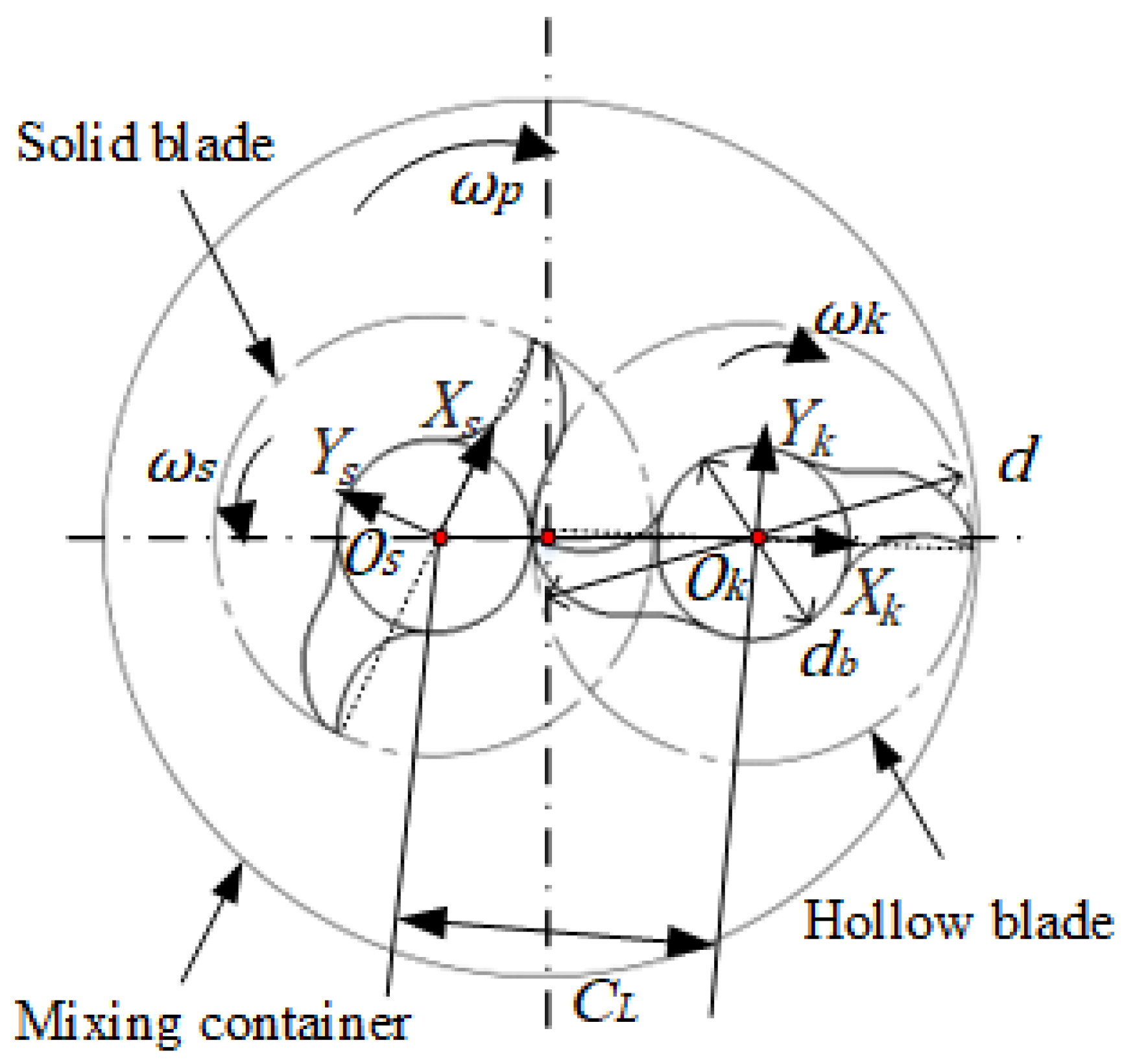
3.1. Mixer Blade Surface Modeling

As for a spiral surface, it can be generated by a bus that moves spirally around an axis. The radial section curve of the positive spiral surface at any height is the same as the shape of the bus, but there is a certain rotation angle between them. Two blades of the mixer are positive spiral surfaces, and the axis coincides with the rotating axis of the two blades, respectively, but the hollow blades are left-handed and the solid blades are right-handed.
Firstly, we study a radial section curve of the blade. As shown in Figure 4, Os and Ok represent the solid and hollow blade radial section center, the revolution speed of the blade is set to ωp, the hollow blade rotation speed is set to ωk, the solid blade rotation speed is set to ωs, the ratio of the hollow blade revolution speed to the rotation speed is set to C, the rotation speed ratio of the hollow blade to the solid blade is set to κ, and ωk = κωs. The diameter of the blade is d, the radius is r, the radius of the base circle is db, the height is h1, and r = d/2.
Then, the coordinates (xk, yk) of any point on the radial section curve of the hollow blade are given by the following equations.
x k = C L cos θ k r + σ cos θ k θ k / κ + β y k = C L sin θ k + r + σ sin θ k θ k / κ + β 0 θ k β
where CL is the center distance between the design centers of the two blades, θk is the angular displacement of the hollow blade during rotation, θk = ωkt, σ is the gap between the blades, and β is the kneading angle of the two blades, with β = arccos (CL/d).
The coordinates (xs, ys) of any point on the radial section curve of the solid blade are given by the following equations.
x s = C L cos θ s r + σ cos θ s + κ θ s β y s = C L sin θ s + r + σ sin θ s + κ θ s β 0 θ s 0.5 β
where θs is the angular displacement at the solid blade rotating time, t, and θs = ωst.
The blade section curve is composed of a base circle curve and a four-segment curve. The section curve of the two blades can be obtained by a programming calculation, as shown in Figure 5.
The blade spiral surface can be formed by rotating the section curve around its center Os and Ok in a plane whilst moving uniformly along the normal direction of the section. The helical angle of the solid blade is set to αs, and its mathematical model M(x,y) of the radial section curve of its lower end face is given by the following equation.
M : x = f ξ 0 y = g ξ 0 ; ξ 0 ξ ξ n
ξ is the rotation angle of the sectional curve, ξ0 is the initial value of the rotation angle, where ξ0 = 0, and ξn is the final value of the rotation angle, where ξn = hcot(αs)/r.
Corresponding to different rotation angles ξ, the blade section curve is at different heights; then, the mathematical model M(u,v) of the blade section curve at any height is obtained.
M : u = x cos ξ y sin ξ v = x sin ξ + y cos ξ 0 ξ h / r cot α
It can be seen from the above that there should be two variables in the equation of the blade surface, the variable t in the blade section curve and the rotation angle ξ in the process of generating the blade spiral surface from the section curve. Using the vector function containing two variables, the following is obtained:
p t , ξ = u t , ξ , v t , ξ , z t , ξ

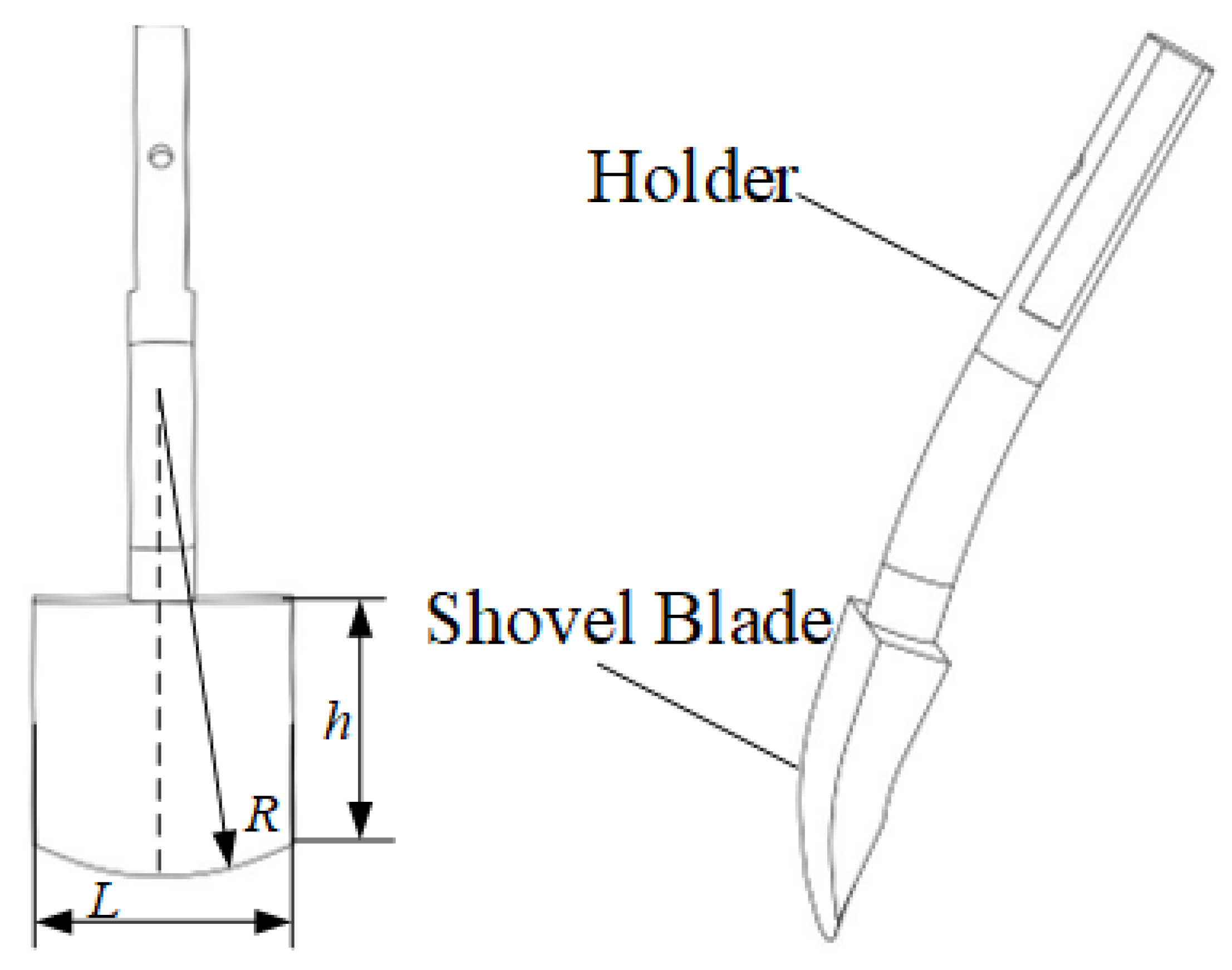
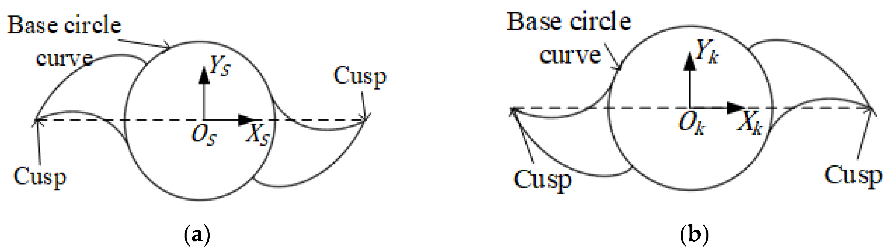
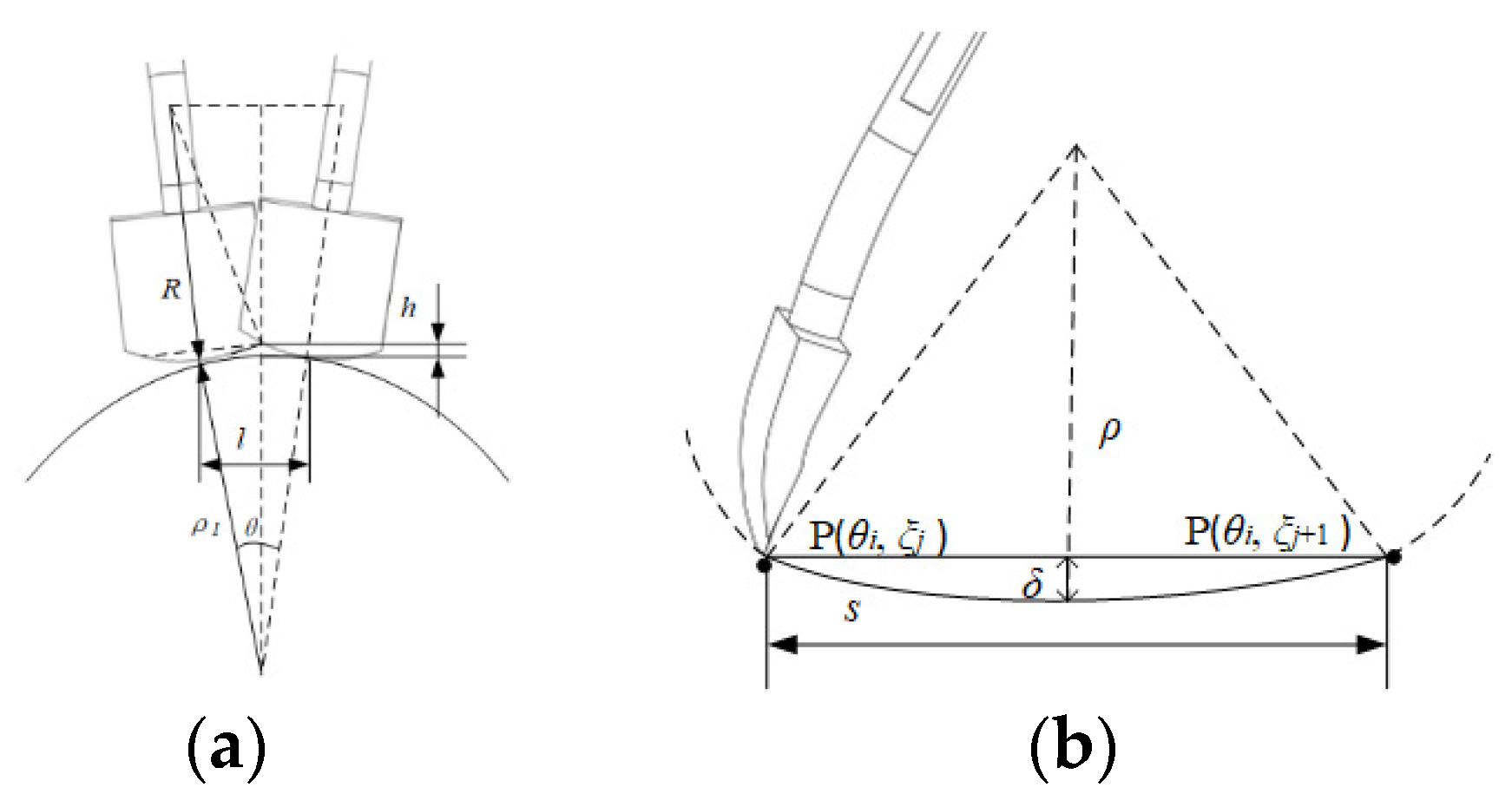
3.2. Geometric Parameters of Mixer Blade Surface

The surface expression of the blade surface is given by p t , ξ = u t , ξ , v t , ξ , z t , ξ . The first and second fundamental forms of the surface are given by the following equations.
Ι = E d t 2 + 2 F d t d ξ + G d ξ 2
Ι Ι = L d t 2 + 2 M d t d ξ + N d ξ 2
In the formulas, E, F, and G are class Ι basic quantities, and L, M, and N are class ΙΙ basic quantities.
p η η , ξ = p η , ξ η = X η , Y η , Z η p ξ η , ξ = p η , ξ ξ = X ξ , Y ξ , Z ξ E η , ξ = p η , ξ p η η , ξ F η , ξ = p η η , ξ p ξ η , ξ G η , ξ = p ξ η , ξ p ξ η , ξ
p η η η , ξ = p η η , ξ η p η ξ η , ξ = p η η , ξ ξ p ξ ξ η , ξ = p ξ η , ξ ξ L η , ξ = e η , ξ p η η η , ξ M η , ξ = e η , ξ p η ξ η , ξ N η , ξ = e η , ξ p ξ ξ η , ξ
In the above expressions, e η , ξ is the unit normal vector corresponding to any point on the solid blade surface p η , ξ , which can be obtained by the following equation:
e η , ξ = p η × p ξ p η × p ξ = p η × p ξ E G F 2
Then, the Gaussian curvature K and the average curvature H at a point on the surface can be calculated by the following formula:
K = L N M 2 E G F 2 = e · p t t e · p ξ ξ e · p t ξ 2 p t 2 p ξ 2 p t · p ξ = G F
H = E N 2 F M + G L 2 E G F 2
Based on the positive and negative values of K and H, the surfaces can be divided into concave, convex, planar, and saddle surfaces.

4. Path Planning

4.1. Mixer Blade Surface Slice

In order to improve the robot path planning efficiency and cleaning efficiency, the principle of blade surface segmentation with similar surface characteristics is selected. In this paper, the blade surface is segmented according to the normal vector e, the Gaussian curvature K, and mean curvature H of the surface.
Firstly, the parameter curve is used to mesh the whole blade surface; then, the discrete grid points are determined through the intersection of the θ curve and ξ curve. Blade surface segmentation is completed in three steps. Firstly, the blade surface is roughly divided according to the sign of the Gaussian curvature K and average curvature H. Then, according to the discrete point position and normal vector e, the surface that has been roughly divided is divided finely by the k-means++ clustering algorithm. Next, the parameter curve is selected as the boundary of the sub-surface. All the sub-surfaces of the blade surface are eventually obtained.
According to the combination of the sign of the Gaussian curvature K and average curvature H, the discrete points of the surface can be roughly divided into four categories: plane (K = 0, H = 0), convex surface (K ≥ 0, H < 0), concave surface (K ≥ 0, H > 0), and concave surface (K < 0, H ≠ 0). Then, the k-means++ clustering algorithm can be used to divide the surfaces finely. The line is selected in the parameter plane to determine the boundary of the sub-surface. The number of discrete points belonging to two sub-surfaces is basically the same on the line that has been selected. In addition, the boundaries of the sub-surfaces are determined by mapping the boundary parameter lines to Cartesian three-dimensional space.

4.2. Robot Subpath Planning

The iso-parametric line method is used to generate the cleaning path of the robot on the blade surface. For the blade surface parameter equation p(θ,ξ), the ξ curve is the spiral line on the spiral surface, and the θ curve is the radial section curve of the spiral surface. It is necessary to clean the propellant into a mixing pot during the actual cleaning process. So, the ξ curve family should be selected as the cleaning path curve, and the direction of the ξ curve family can only be downward.
The front end of the cleaning tool is a circular surface. So, residual propellant is produced in two path curves during cleaning. The residual height of the residual propellant is defined as h. The row spacing l between paths and the step length s between path points can be calculated by the residual height requirement. The maximum allowable height of the residual propellant on the cleaned blade surface is defined as δ max , which is the maximum allowable value of the blade cleaning error.
There is a relationship between the residual height h between two path curves and the maximum allowable value of the blade cleaning error δ max .
h δ max
Taking the convex blade surface as an example, which is shown in Figure 6, the residual height h can be approximately calculated by the following equation.
h = ρ 1 + R cos θ 2 ρ 1 R 2 ρ 1 + R sin θ 2 2
In the above formula, ρ 1 is the radius of the curvature on the path curve along the subnormal direction, and θ is the angle between two lines that are determined by the connection of two arctangent points and the center of curvature circle. The values of sin(θ/2) and cos(θ/2) can be calculated by the following formulas.
sin θ 2 = l 2 ρ 1
cos θ 2 = 1 sin θ 2 2 = 1 l 2 ρ 1 2
The following formula is derived by simultaneously solving Formulas (13)–(16).
l ρ 1 4 ρ 1 + R 2 δ max + ρ 1 2 2 ρ 1 2 + 2 ρ 1 δ max + 2 ρ 1 R δ max 2 ρ 1 + R δ max + ρ 1
The row spacing l on the concave surface of the blade is calculated by referencing the convex calculation method, and the row spacing l is supposed to satisfy the following formula.
l ρ 1 4 ρ 1 R 2 ρ 1 δ max 2 2 ρ 1 2 2 ρ 1 δ max 2 ρ 1 R + δ max 2 ρ 1 R ρ 1 δ max
Due to the similarity of the geometric properties of the subfaces, it is supposed to take the same row spacing on the same sub-facet. The value of θ in the formula is the minimum curvature radius along the subnormal direction of the path curve.
If the robot fits the curve by linear interpolation, the maximum chord deviation δ is the maximum distance between the straight-line segment and the curve segment in the unit step. As shown in Figure 6b, after the cleaning operation is completed according to the robot path formed by interpolation, the maximum blade cleaning error δ max generally occurs at the position of the maximum chord deviation. Therefore, after setting the step size, the following equation should be satisfied between the maximum chord deviation δ and the maximum allowable value of the blade cleaning error δ max .
δ δ max
The maximum chord deviation can be approximately calculated according to the radius of the normal curvature of the point along the direction of tool movement.
δ = ρ ρ 2 s 2 2
The following formula can be obtained by substituting Formula (20) into Formula (19).
s 2 2 ρ δ max δ max 2
The same step size is taken on the same subface by referring to the row spacing settings. The value of ρ is the radius of the normal curvature of the point with the largest chord deviation along the path of the subface along the tool path.
According to the row spacing and step length, the robot cleaning subpath is generated by the iso-parametric line method.

4.3. Figures, Tables, and Schemes

A complete blade cleaning path needs to combine the subpaths in a certain order. In the process of subpath combination connection, the order selection of subpaths will directly affect the cleaning time. In order to shorten the cleaning time and improve the blade cleaning efficiency, the robot path combination process should be optimized to minimize the total cleaning time. The problem of the blade surface subface path combination can be mathematically modeled by the generalized traveling salesman problem (GTSP).
Since the path planning on the subpath has been completed, the time consumed is constant. So, the connections of the different subpaths only need to be considered in the subpath combination optimization. V = v 1 , v 2 , , v m is a set of subpaths. m is the number of subpaths. E = v i , v j | i j , v i , v j V is a set of subpath connection methods. W = {w(vi, vj), vi, vj V, i j}, where w(vi, vj) represents the weight value connecting the i th subpath to the j th subpath. In this article, the weight value is the time it takes for the robot to travel from the end of path i to the start of path j. Acceleration and deceleration during robot operation need to be considered when the running time of the robot is calculated.
The weight value w(vi, vj) can be calculated by the following formula.
L = v max 2 / a
D i j = B i A j
w v i , v j = D i j a D i j L D i j L v max + 2 v max a D i j > L
where v max is the maximum speed of the robot, a is the operating acceleration of the robot, and B i A j is the distance from the terminal point Bi of path i to the starting point Aj of path j.
The subpath combination problems can be solved according to the optimization objective function. T is used to represent the time taken for the subpath connections.
min T = min i = 1 m 1 w v i , v i + 1

5. Blade Path Planning Simulation and Experimental Verification

5.1. Surface Modeling of Solid Blade Part

The partial surface of the solid blade of the mixer, which is shown in Figure 7a, is selected to realize the simulation experiment of surface path planning. After inputting the design parameters of the solid blades, the surface parameter equation of this part of the surface is obtained. The three-dimensional model of this part of the surface, as shown in Figure 7b, can be drawn by programming.
x = 539 cos θ 368 cos ( 3 θ 42 ) cos ξ 539 sin θ 368 sin ( 3 θ 42 ) sin ξ y = 539 cos θ 368 cos ( 3 θ 42 ) sin ξ + 539 sin θ 368 sin ( 3 θ 42 ) cos ξ z = 737 ξ 0 θ 21 0 ξ 1.5

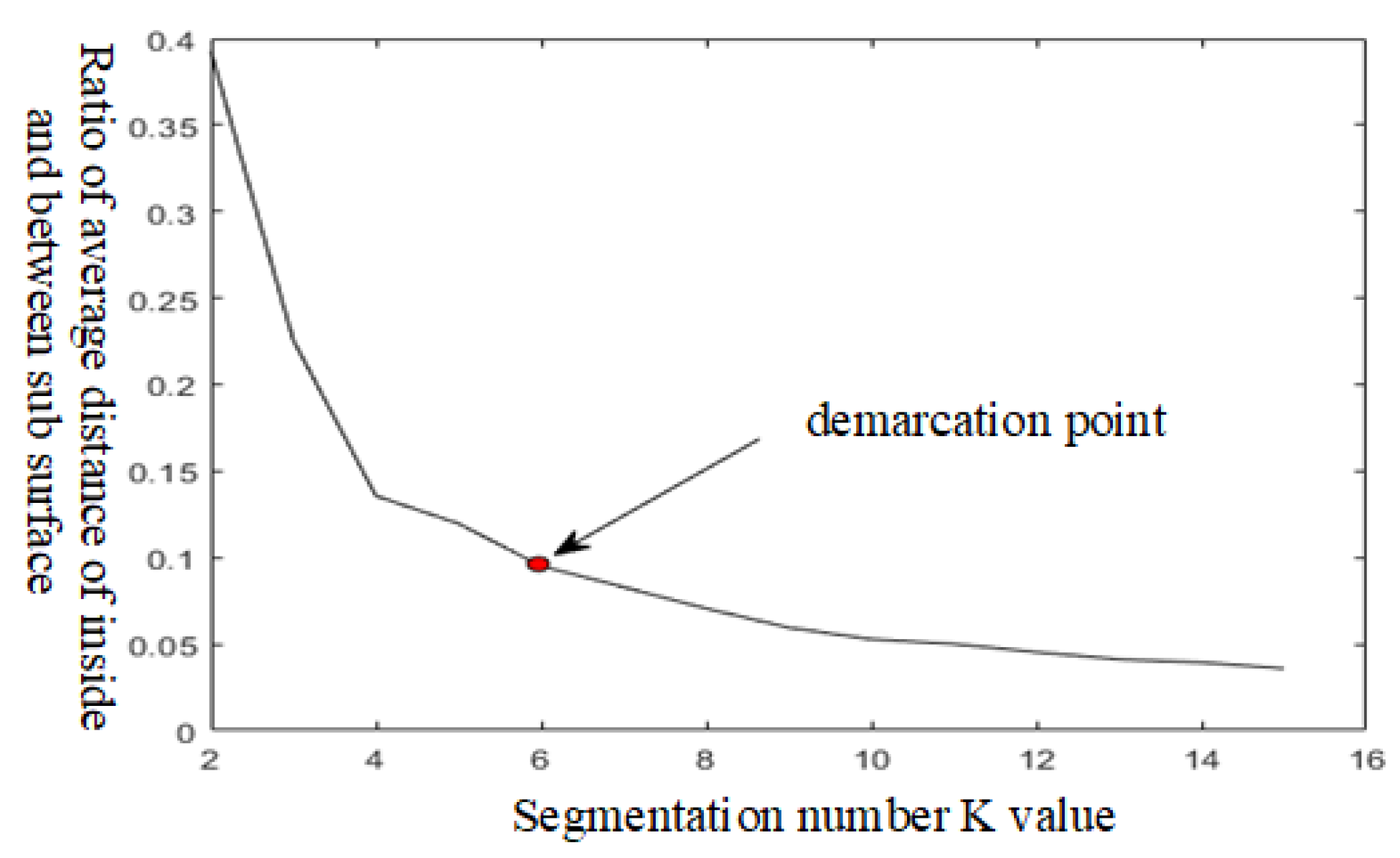
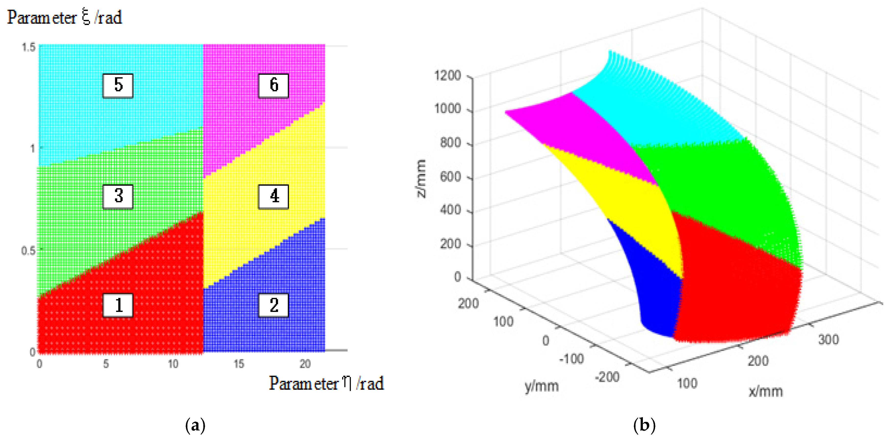
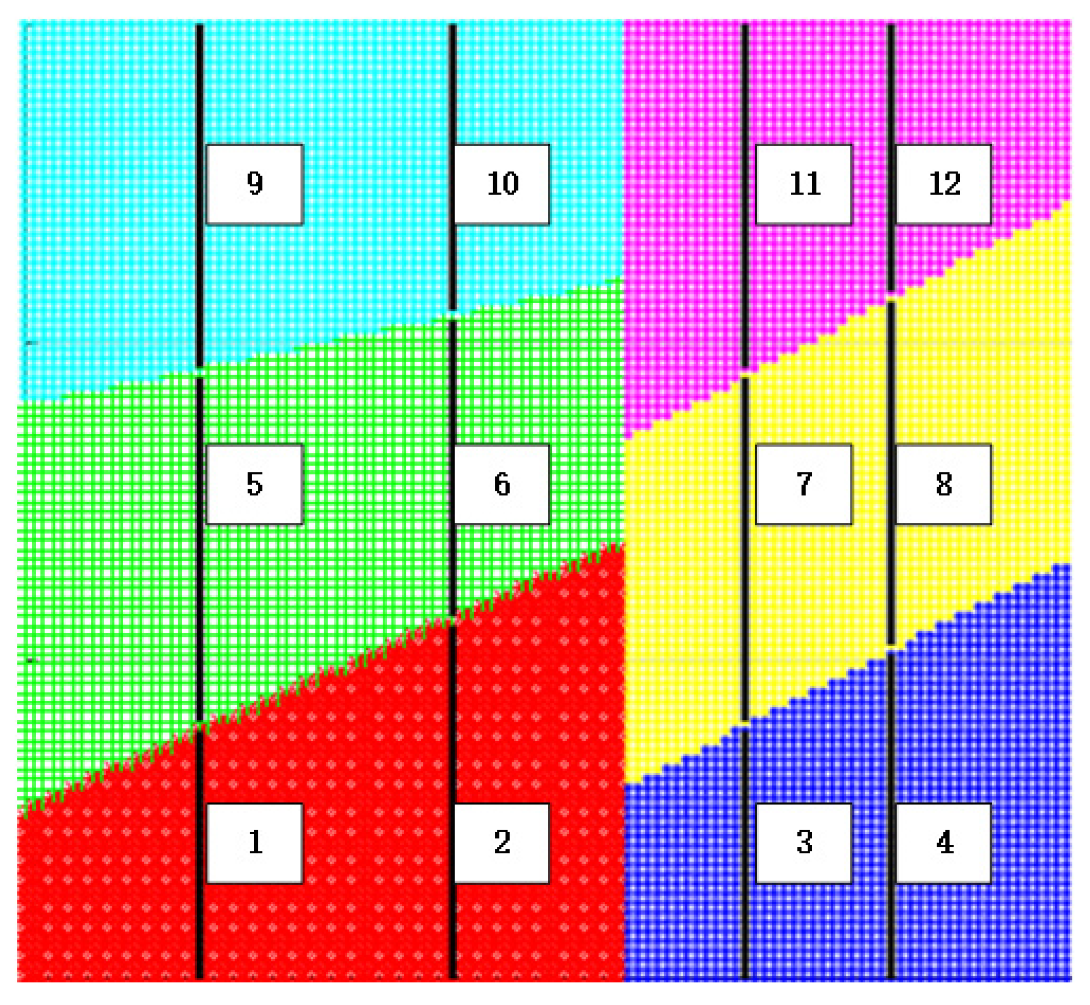
5.2. Surface Subdivision of the Solid Blade Partial Surface

The spacing of the θ curve is selected to be 0.2, and the spacing of the ζ curve is selected to be 0.015. The blade surface is discretely meshed according to the value of θ and ζ. Then, the set of discrete points on the surface can be obtained. Then, the Gaussian curvature K, average curvature H, and normal vector e of each discrete mesh point can be solved. Using the sign of K and H, the surface is roughly divided. According to the division results, there are only concave surfaces on this part of the surface.
This surface is taken as an example to further subdivide the surface. The relationship between the number of fragments k of the concave sample set and the ratio of the average distance between the sub-surfaces can be drawn. The relationship curve is shown in Figure 8. The demarcation point occurs when the value of k is 6. Therefore, when the concave sample is subdivided, using the k-means++ clustering algorithm, the value of k should be set to 6. The attribute value of each sample in the concave sample set is normalized. The results of the subdivision are shown in Figure 9. After data processing is completed, the k-means++ clustering algorithm for is applied surface subdivision. The discrete points on the subdivided sub-surfaces are mapped from the Cartesian three-dimensional space to the two-dimensional parameter plane. Some line segments in the parameter plane are selected as subface boundaries (black line segment in Figure 9). The concave subdivision results are shown in Figure 10.

5.3. Path Planning of Solid Blade Partial Surface

The main parameters of the cleaning tool are shown in Table 1. The maximum allowable height δ max of propellant residue on the blade surface during actual cleaning is 2 mm. The parameter ρ 1 of each sub-surface is the minimum curvature radius along the subnormal direction of the path curve. The value of ρ is the normal radius of curvature along the direction of tool movement for the point where the maximum chord deviation occurs on the subface path, as shown in Table 2. The settable maximum row spacing l and the settable maximum step size s can be calculated on each sub-surface by bringing the parameters into the calculation, as shown in Table 3. According to the maximum row spacing and step size limit allowed by each sub-surface, the path planning of each sub-surface is performed, as shown in Figure 11.
In this paper, the genetic algorithm is used to solve the generalized traveling salesman mathematical model of the blade subpath combination. The operation parameters of the genetic algorithm are set, respectively. The length of the chromosome is set to 12, which is twice the number of sub-surfaces. The population number is 20, the number of iterations is 500, the crossover probability is 0.7, and the mutation probability is 0.1. The optimization path solver is run 30 times. After 500 generations are iterated, the optimal solution of the sub-surface cleaning path combination can be obtained. The subpath sorting of the optimal solution is 10→6→2→11→7→3→12→8→4→9→5→1, and the total time spent on the corresponding subpath connection is 44.3172 s.

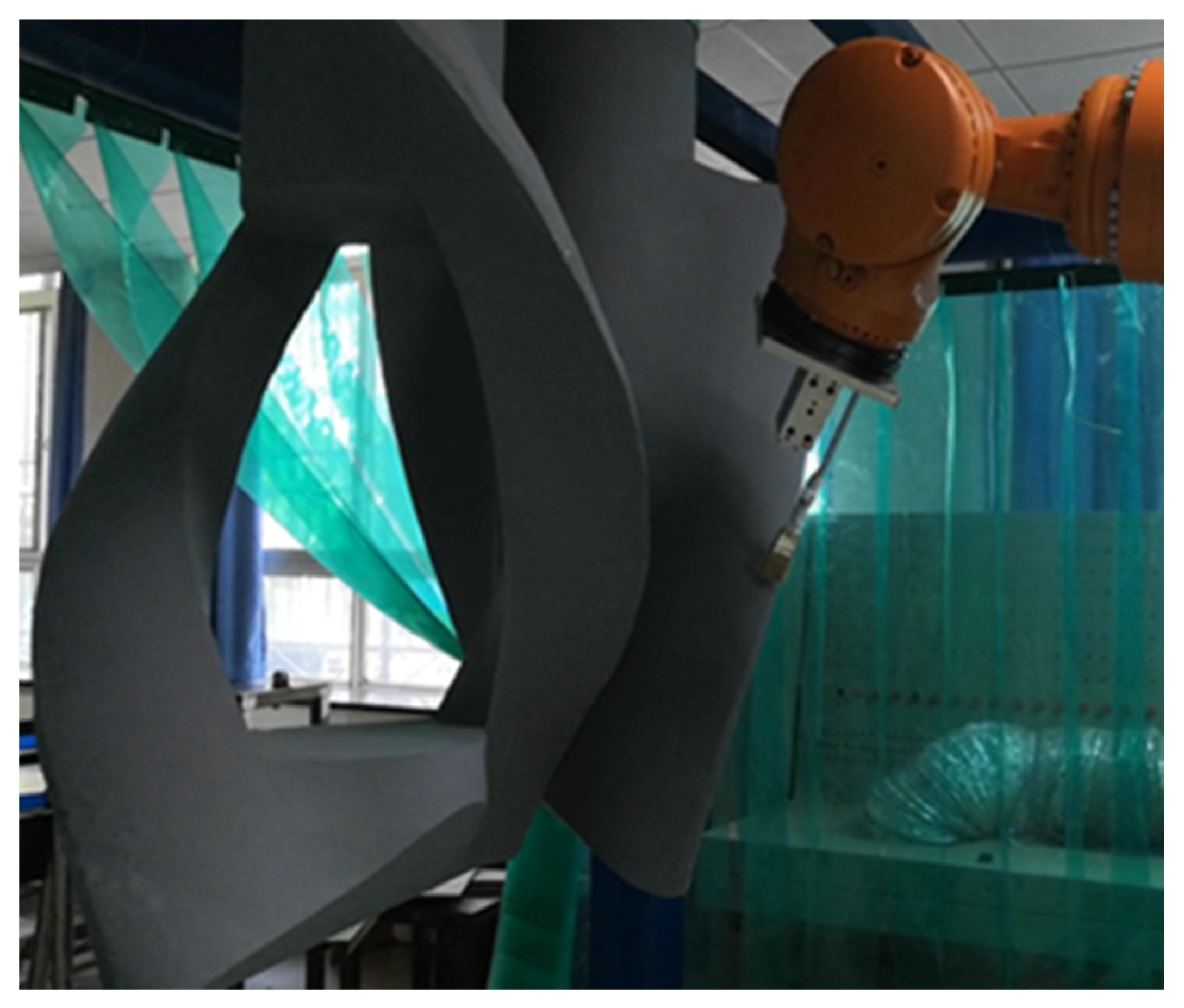
5.4. Experimental Verification of Robot Path Planning

To verify the practical applicability of the proposed method, each subpath task generated by our algorithm through simulation experiments was programmed into and executed by a physical KUKA KR60L30-3 industrial robot (KUKA, Augsburg, Germany). The robot was tasked with tracing the planned paths on a mock-up section of the vertical mixer blade, as shown in Figure 12.
The time required for different subpath arrangements in this physical experiment is shown in Table 4.

6. Conclusions

The proposed robotic cleaning path planning method addresses the critical challenges of vertical mixer blade maintenance in aerospace propellant production by integrating geometric modeling, intelligent segmentation, and optimized path generation. Through mathematical modeling of the helical blade surface and development of a k-means++-clustering-based segmentation approach with parameterized boundary determination, the method achieves functional sub-region division that accounts for residue distribution and cleaning requirements. The subsequent path planning phase generates efficient cleaning trajectories using iso-parametric curves while formulating the multi-subregion path combination as a GTSP problem to minimize operational time. Experimental validation on concave blade sections demonstrates the method’s effectiveness in maintaining cleaning coverage and safety while significantly reducing processing time, providing a practical solution for hazardous environment maintenance that balances precision with operational efficiency. This approach establishes a strong foundation for future extensions, which will focus on enhancing real-time adaptability to dynamic residue conditions, incorporating robustness for structurally compromised surfaces, and exploring multi-objective optimization strategies that include energy efficiency and tool wear, alongside advancing multi-robot coordination for increasingly complex industrial cleaning scenarios.

Author Contributions

Methodology, Z.S. and J.L.; writing—original draft preparation, L.G.; visualization, N.C.; writing—review and editing, X.Q. and Z.W. All authors have read and agreed to the published version of the manuscript.

Funding

This research was co-supported by the Major R & D projects in Shaanxi Province (Grant No. 2019zdzx01-01-0), the Key R & D Projects of Shaanxi Province (Grant No. 2021GY-302), the Shaanxi Provincial Technological Innovation Guidance Program (Grant No. 2023KXJ-176), and the Xi’an Science and Technology Plan (Grant No. 23KGDW0029-2022).

Data Availability Statement

The original contributions presented in this study are included in the article. Further inquiries can be directed to the corresponding author(s).

Conflicts of Interest

Author Zhouzheng Shi was employed by the company AVIC Xinxiang Aviation Industry Company Limited. Author Zhanxi Wang was employed by the company Shaanxi Dao Bo New Material Technology Co., Ltd. The remaining authors declare that the research was conducted in the absence of any commercial or financial relationships that could be construed as a potential conflict of interest.

References

  1. Takahashi, A.; Kitagawa, K.; Shimada, T. WITHDRAWN: Evaluation of safety distance for blast of hybrid rocket propellants. Fire Saf. J. 2020, 103145. [Google Scholar] [CrossRef]
  2. Furlong, A.J.; Bond, N.K.; Pegg, M.J.; Hughes, R.W. Evaluation of dust and gas explosion potential in chemical looping processes. J. Loss Prev. Process Ind. 2024, 89, 105277. [Google Scholar] [CrossRef]
  3. Kang, Y.; Xia, X.; Wu, Z.; Cheng, Z. Visualization of integrated failure consequences of hazardous chemical leakage and explosion. J. Loss Prev. Process Ind. 2024, 92, 105464. [Google Scholar] [CrossRef]
  4. Figgis, B.; Bermudez, V.; Garcia, J.L. PV module vibration by robotic cleaning. Sol. Energy 2023, 250, 168–172. [Google Scholar] [CrossRef]
  5. Shin, D.; Choi, Y.; Soon, Z.Y.; Kim, M.; Jang, M.-C.; Seo, J.-Y.; Kang, J.-H.; Shin, K.; Jung, J.-H. Chemical hazard of robotic hull in-water cleaning discharge on coastal embryonic fish. Ecotoxicol. Environ. Saf. 2023, 253, 114653. [Google Scholar] [CrossRef] [PubMed]
  6. Zhang, H.-Y.; Lin, W.-M.; Chen, A.-X. Path planning for the mobile robot: A review. Symmetry 2018, 10, 450. [Google Scholar] [CrossRef]
  7. Zhao, S.; Zheng, T.; Wang, C.; Yang, Z.; Xu, T.; Zhu, Y.; Zhao, J. Sigmoid angle-arc curves: Enhancing robot time-optimal path parameterization for high-order smooth motion. Robot. Comput. Integr. Manuf. 2025, 92, 102884. [Google Scholar] [CrossRef]
  8. Zhang, Y.; Zhang, G.; Xu, X.; Zhao, Q. Research on Region Division of Large Workpiece Based on Dexterous Workspace of Robot. In Proceedings of the 2021 5th International Conference on Electrical, Automation and Mechanical Engineering (EAME 2021), Journal of Physics: Conference Series, Guangzhou, China, 17–18 September 2021; p. 012059. [Google Scholar]
  9. Li, L.; Shi, D.; Jin, S.; Yang, S.; Zhou, C.; Lian, Y.; Liu, H. Exact and heuristic multi-robot dubins coverage path planning for known environments. Sensors 2023, 23, 2560. [Google Scholar] [CrossRef]
  10. Sun, Y.; Sun, S.; Xu, J.; Guo, D. A unified method of generating tool path based on multiple vector fields for CNC machining of compound NURBS surfaces. Comput. Aided Des. 2017, 91, 14–26. [Google Scholar] [CrossRef]
  11. Yuan, E.-T.; Shao, B. Tool-path generation of multi-axis machining for subdivision surface. AASRI Procedia 2012, 3, 60–65. [Google Scholar] [CrossRef]
  12. Bendjebla, S.; Cai, N.; Anwer, N.; Lavernhe, S.; Mehdi-Souzani, C. Freeform machining features: New concepts and classification. Procedia CIRP 2018, 67, 482–487. [Google Scholar] [CrossRef]
  13. Liu, H.; Zhang, E.; Sun, R.; Gao, W.; Fu, Z. Free-Form Surface Partitioning and Simulation Verification Based on Surface Curvature. Micromachines 2022, 13, 2163. [Google Scholar] [CrossRef]
  14. Sun, J.; Xiang, S.; Zhou, T.; Cheng, T. Sampling Point Planning for Complex Surface Inspection based on Feature Points under Area Division. Int. J. Adv. Manuf. Technol. 2023, 127, 717–732. [Google Scholar] [CrossRef]
  15. Han, X. Research on the Regional Division of Free Surface Machining Based On K-Means Clustering Algorithm. In Proceedings of the 2016 7th International Conference on Mechatronics, Control and Materials (ICMCM 2016), Changsha, China, 29–30 October 2016; pp. 312–317. [Google Scholar]
  16. Wang, G.; Hua, X.; Xu, J.; Song, L.; Chen, K. A deep learning based automatic surface segmentation algorithm for painting large-size aircraft with 6-DOF robot. Assem. Autom. 2020, 40, 199–210. [Google Scholar] [CrossRef]
  17. Li, X.; Zhang, Y.J.; Yang, X.; Xu, H.; Xu, G. Point cloud surface segmentation based on volumetric eigenfunctions of the Laplace-Beltrami operator. Comput. Aided Geom. Des. 2019, 71, 157–175. [Google Scholar] [CrossRef]
  18. Kalogerakis, E.; Averkiou, M.; Maji, S.; Chaudhuri, S. 3D shape segmentation with projective convolutional networks. In Proceedings of the IEEE Conference on Computer Vision and Pattern Recognition, Honolulu, HI, USA, 21–26 July 2017; pp. 3779–3788. [Google Scholar]
  19. Vo, A.-V.; Truong-Hong, L.; Laefer, D.F.; Bertolotto, M. Octree-based region growing for point cloud segmentation. ISPRS J. Photogramm. Remote Sens. 2015, 104, 88–100. [Google Scholar] [CrossRef]
  20. Li, J.; Zou, L.; Luo, G.; Wang, W.; Lv, C. Enhancement and evaluation in path accuracy of industrial robot for complex surface grinding. Robot. Comput. Integr. Manuf. 2023, 81, 102521. [Google Scholar] [CrossRef]
  21. Zhang, L.; Ding, L.; Ullah, S.; Hu, T.; Xu, Y.; Chen, L.; Hanif, M. An improved medial axis path generation algorithm for selective laser melting. Rapid Prototyp. J. 2020, 26, 1751–1759. [Google Scholar] [CrossRef]
  22. Chalvin, M.; Campocasso, S.; Hugel, V.; Baizeau, T. Layer-by-layer generation of optimized joint trajectory for multi-axis robotized additive manufacturing of parts of revolution. Robot. Comput. Integr. Manuf. 2020, 65, 101960. [Google Scholar] [CrossRef]
  23. Xu, K.; Li, Y.; Yang, M. Quasi-optimal tool trajectories for high speed 2.5 D process based on morphological transformation. Comput. Aided Des. 2020, 129, 102920. [Google Scholar] [CrossRef]
  24. Holowenko, O.; Troll, C.; Ihlenfeldt, S.; Majschak, J.-P. A Novel Adaptive Interpolation Approach for the Implementation of Operating-Speed-Dependent Motion Profiles in Processing Machines. Eng. Sci. Technol. Int. J. 2021, 24, 1308–1317. [Google Scholar] [CrossRef]
  25. Nieto Bastida, S.; Lin, C.-Y. Autonomous trajectory planning for spray painting on complex surfaces based on a point cloud model. Sensors 2023, 23, 9634. [Google Scholar] [CrossRef]
  26. Huang, Y.; Gu, Y.; Zheng, Z. Research on the path planning of hair-insertion robot arm based on ant colony optimization. In Proceedings of the 2018 37th Chinese Control Conference (CCC), Wuhan, China, 25–27 July 2018; pp. 5191–5195. [Google Scholar]
  27. Jiang, J.; Guo, Y.; Huang, Z.; Zhang, Y.; Wu, D.; Liu, Y. Adjacent surface trajectory planning of robot-assisted tooth preparation based on augmented reality. Eng. Sci. Technol. Int. J. 2022, 27, 101001. [Google Scholar] [CrossRef]
  28. Hauth, S.; Richterich, C.; Glasmacher, L.; Linsen, L. Constant cusp toolpath generation in configuration space based on offset curves. Int. J. Adv. Manuf. Technol. 2011, 53, 325–338. [Google Scholar] [CrossRef]
  29. Yang, X.; Yue, X.; Cai, Z.; Zhong, S. Research on the trajectory planning and global optimization strategy of cold spraying technique for complex products coating preparation. Robot. Intell. Autom. 2024, 44, 258–269. [Google Scholar] [CrossRef]
  30. Wang, N.; Wang, H.; Jiang, Y. Optimization on laser cutting process path based on bidirectional ant colony algorithm. Forg. Stamp. Technol. 2020, 45, 30–35. [Google Scholar]
Figure 1. Equipment layout of robot blade cleaning system.
Jmmp 09 00198 g001
Figure 2. Structural parameters of KUKA KR60L30-3 robot. (a) The structure size parameters of KUKA KR60L30-3 robot; (b) motion coordinate system of KUKA KR60L30-3 robot.
Jmmp 09 00198 g002
Figure 3. Shape and main geometric parameters of cleaning system end effector.
Jmmp 09 00198 g003
Figure 4. Vertical mixer blade motion diagram.
Jmmp 09 00198 g004
Figure 5. (a) Solid blade section curve; (b) hollow blade section curve.
Jmmp 09 00198 g005
Figure 6. (a) Path intervals calculation; (b) diagram of step calculation.
Jmmp 09 00198 g006
Figure 7. (a) Solid blade part surface diagram; (b) three−dimensional model of solid blade partial surface.
Jmmp 09 00198 g007
Figure 8. The relationship curve between the number of fragments and the average distance between sub-surfaces.
Jmmp 09 00198 g008
Figure 9. Part of the blade concave clustering results and boundary determination (parameter plane).
Jmmp 09 00198 g009
Figure 10. (a) Final segmentation results of parameter plane; (b) final fragment results.
Jmmp 09 00198 g010
Figure 11. Planning result of subpath on the partial concave section of the blade (parameter plane).
Jmmp 09 00198 g011
Figure 12. Robot path planning experiment.
Jmmp 09 00198 g012
Table 1. Main parameters of cleaning tool.
Parameter NameWidth L/mmHeight h/mmFront Arc Radius/mm
numerical value1008095
Table 2. Sub-surface parameters of blade partial surface.
Subchip Number123456
ρ 1 / mm 1842.492675.821842.492675.821842.492675.82
ρ/mm139.57115.47139.57115.47139.57115.47
Table 4. Subpath arrangement and cleaning time.
Subpath ArrangementSubpath Connection Time
10→6→2→11→7→3→12→8→4→9→5→144.3172 s
10→6→2→12→8→4→11→7→3→9→5→144.3396 s
11→7→4→3→9→5→1→12→8→10→6→245.9039 s
9→10→6→2→11→7→3→12→8→4→5→145.9275 s
9→10→6→2→12→8→4→11→7→3→5→145.9281 s
10→9→6→2→12→8→4→11→7→3→5→146.0785 s
10→5→1→11→7→3→12→8→4→9→6→246.2415 s
9→6→2→10→5→1→12→8→4→11→7→346.2861 s
11→7→3→10→5→1→12→8→4→9→6→246.3252 s
12→10→6→11→7→3→8→4→2→9→5→147.4891 s
10→6→4→2→7→1→8→5→3→12→9→1161.8584 s
Table 3. Maximum allowable row spacing and step length of each blade sub-surface.
Subchip Number123456
l/mm68.7691.2368.7691.2368.7691.23
s/mm171.65206.87171.65206.87171.65206.87
Disclaimer/Publisher’s Note: The statements, opinions and data contained in all publications are solely those of the individual author(s) and contributor(s) and not of MDPI and/or the editor(s). MDPI and/or the editor(s) disclaim responsibility for any injury to people or property resulting from any ideas, methods, instructions or products referred to in the content.

