Article

On the Use of Compressed Air and Synthetic Biodegradable Cutting Fluid to Enhance the Surface Quality of WAAM–CMT Manufactured Low-Alloy Steel Parts During Post-Processing Milling with Different Cooling–Lubrication Strategies

by
Déborah de Oliveira
1,*,
Marcos Vinícius Gonçalves
2,
Guilherme Menezes Ribeiro
1,
André Luis Silva da Costa
1,
Luis Regueiras
3,
Tiago Silva
3,*,
Abílio de Jesus
4,
Lucival Malcher
3 and
Maksym Ziberov
1
1
Mechanical Engineering Department, University of Brasilia, Asa Norte, Brasília 70910-900, DF, Brazil
2
Department of Materials and Processes, Technological Institute of Aeronautics, Vila das Acacias, São José dos Campos 12228-900, SP, Brazil
3
Institute of Science and Innovation in Mechanical and Industrial Engineering, Rua Dr. Roberto Frias, 4200-465 Porto, Portugal
4
LAETA, Faculty of Engineering, University of Porto, Rua Dr. Roberto Frias, 4200-465 Porto, Portugal
*
Authors to whom correspondence should be addressed.
J. Manuf. Mater. Process. 2025, 9(6), 193; https://doi.org/10.3390/jmmp9060193
Submission received: 6 May 2025 / Revised: 23 May 2025 / Accepted: 30 May 2025 / Published: 10 June 2025

Abstract

Additive manufacturing (AM) stands out for its variable applications in terms of material, quality, and geometry. Wire Arc Additive Manufacturing (WAAM) is remarkable for producing large parts in reduced times when compared to other AM methods. The possibility of producing a part with a near-net shape not only enhances productivity but also reduces resources usage. However, parts produced by WAAM may need post-processing by machining to achieve functional surface requirements. Therefore, it is important that machining, even if minimized, does not lead to a significant environmental impact. In this sense, this work evaluates the effect of using compressed air, dry cut, and synthetic biodegradable cutting fluid at varying nozzle positions and flow rates on the surface quality of ER70S-6 steel produced by WAAM, after milling with TiAlN-coated carbide tools. To analyze the surface roughness, parameters Ra, Rq, and Rz were measured and microscopy was used to further evaluate the surfaces. The surface hardness was also evaluated. The results showed that a flow rate of 10 L/min promotes better surface quality, which can be further improved using compressed air, leading to a surface quality 50% better when compared to dry cutting. Dry cut was not suitable for machining ER70S-6 WAAM material as it resulted in rough surface texture with an Rz = 4.02 µm. Compressed air was the best overall condition evaluated, achieving a 36% Ra reduction compared to dry cutting, the second-lowest hardness deviation at 6.51%, and improved sustainability by eliminating the need for cutting fluid.

1. Introduction

Among Additive Manufacturing (AM) methods, wire arc additive manufacturing (WAAM) offers advantages such as low material waste, reduced energy consumption, and short lead times [1]. It enables the fabrication of optimized, novel designs [2], but the process requires precise control as deposition parameters significantly affect part geometry [3]. In fact, not only the part geometry, but accuracy, hardness variation, and high surface roughness are still challenges to be addressed in WAAM parts both during deposition and by post-processing.
Among the influencing factors, the heat input/exchange stands out in the WAAM process; the part is subject to high thermal input, and the heat exchange varies for each deposited layer [4]. The deposition strategy also has a significant impact on the final part [5]. Vieira et al. [6] pointed out that for inclined parts, strategies with temperature control contribute to geometry, hindering the collapse of the walls. This impacts, for instance, on part microstructure [7], part hardness distribution [8], corrosion resistance [9], and fatigue life [10]. Researchers also developed studies aiming to contribute to the usage of this method for varied materials with machine learning and prediction frameworks [11] and have tried to predict the defect behaviors for WAAM parts [12].
Different methods can be used to perform WAAM, such as Gas Metal Arc Welding (GMAW), Gas Tungsten Arc Welding (GTAW), and Plasma Arc Welding (PAW). These processes are associated with high deposition rates, high quality, and higher intensity arc, respectively [13]. Regarding productivity, GMAW can be considered the most suitable. Within the GMAW methods, Kah [14] highlights pulsed gas metal arc welding (P-GMAW), Cold Metal Transfer (CMT), double-electrode gas metal arc welding (DE-GMAW), tandem gas metal arc welding (T-GMAW), and alternating current gas metal arc welding (AC-GMAW). To summarize, the main characteristics of those GMAW variations are as follows: P-GMAW associates short circuiting with sprays transfer. It is achieved by applying a low base current to maintain the arc, while using a high peak current to melt and transfer the material; furthermore, it can also be applied in a double-pulsed mode.
The CMT process, developed by Fronius, differs in the droplet transfer mechanism. The filler wire is retracted immediately after a short circuit, enabling the precise control of material transfer. This retraction helps detach the molten droplet at low current and voltage, minimizing heat input. DE-GMAW uses two electrodes to improve the deposition rates, which can also influence heat input. T-GMAW is a process used to increase productivity; it also uses two electrodes but differs from DE-GMAW by usually employing different transfer modes for each electrode, with one working with a continuous arc and the other in pulsed mode. Finally, AC-GMAW combines direct current electrode positive, which provides high melting, with direct current electrode negative, associated with high quality [14].
Among these variations, CMT stands out for WAAM applications since its lower heat input reduces the dilution of base alloys and is also associated with lower residual stresses and structural distortions [15]. Additionally, CMT can be applied to dissimilar materials [15], which are all important characteristics for deposition. Nagasai et al. [16] demonstrated this in their work where they compared the WAAM deposition of ER70S-6 using GMAW and CMT. The authors verified that the optimal deposition parameters resulted in higher rates for CMT (feed speed of 7 m/min) than for GMAW (6.7 m/min), while maintaining better deposition control. Their conclusions showed that CMT can also be associated with higher tensile strength and toughness due to microstructure variations associated with the lower temperatures and higher cooling rates.
As a modern technology, the available studies on WAAM focus on distinct aspects of WAAM deposition, the deposited materials, and their mechanical properties, but fewer studies encompass the complete manufacturing chain [17]. For Murugan and Vinodh [18], when discussing the assembly design, problems in manufacturability and industrial feasibility are within the challenges that should be addressed. The challenges of applying AM to usable parts are associated with the structural variability of the produced parts, since it is difficult to predict their failure due to the presence of defects [19], anisotropy and residual stress, as well as a deficient surface finish, impacting the mechanical performance [10]. The work of Ednie et al. [20] exemplifies this impact as their electron beam melted (EBM) Ti6Al4V had its fatigue life evaluated in samples which were both as-built and polished. The results demonstrate that as-built samples had high Ra values, 35.28 μm, while polished samples reached 1.97 μm, reflecting. This was reflected in the material’s life; at the same stress level of 600 MPa the as-built sample failed after 6284 cycles, while the polished sample only failed after 6,092,199 cycles, representing a 1000-fold increase in fatigue life.
Thus, achieving fully functional parts may require post-processing, which presents an additional challenge as the part’s design must consider it to ensure feasibility [21]. Researchers can use different machining methods to improve the surface quality of AM metals, such as the following [22]:
  • Abrasive methods: Grinding, polishing, lapping, magnetic polishing, and flow polishing.
  • Non-conventional methods: Laser, mechanical and laser peening, ultrasonic cavitation, mechanical buffing, electrochemical finishing, and electroplating.
Those processes can contribute not only to the reduction or surface roughness but to an overall improvement of surface quality, even inducing compressive residual stresses [22]. Yet, if the project requires fine surface features it is also possible to adopt micromachining to obtain those details [23]. For larger parts, such as those produced by WAAM, conventional machining methods might be necessary due to the high waviness of the deposited part, and a machining allowance should be considered for the part to achieve the designed geometry and roughness [24]. The milling process stands out for finishing walls, planes, and free-form geometries.
Chernovol et al. [25] evaluated the machinability of a low-alloy steel deposited by WAAM under different deposition parameters condition. The authors varied cutting speed, feed per tooth, and radial depth of cut, with carbide mills coated with CVD TiCN + Al2O3 + TiN. Among the main results, they observed that parts deposited with lower heat input were harder and smoother, which, as the authors mention, led to better chip formation, more uniform geometry, and thus better surface finish after machining. Since they studied tangential milling, they also highlighted that the depth of cut and feed per tooth should be selected carefully to guarantee stability in chip formation, reducing chatter and other dynamic problems during the cut.
In a similar study, Li et al. [26] machined Al5356 deposited by WAAM, with an uncoated carbide four-flutes end mill. As the cutting parameters were a feed per tooth (fz) of 3.18, 4.76, and 6.35 µm/tooth, a rotation speed of 1000 rpm, and axial and radial depths of cut of 2 and 1 mm, respectively. The authors noted that besides the defects and variations caused by the deposition, the machining proceeded as expected, with fz having a strong influence on the surface quality. The Ra roughness values were approximately 1.1, 1.4, and 1.5 µm from the smallest to the largest fz values.
However, there are few studies on the machining of those alloys. To demonstrate this, a bibliometric evaluation of the Web of Science Core Collection was performed. As search terms the main machining processes—“turning”, “milling”, “drilling” and “grinding”—were used alongside “WAAM” to assess the availability of works regarding this topic. The search was performed in May 2025. All the resulting papers (results) were evaluated to verify if they matched the intended search by their contents, and the actual papers were accessed. The summary of the available research, presented in the order of appearance, can be observed in Table 1. As a comparison, when “Milling” was searched in the same database it resulted in 85,910 available items from 2016 to 2025. When compared to the 76 papers for Milling + WAAM, in the same time interval, this represents less than only 0.1% of the total.
As is possible to notice from Table 1, not only is the literature scarce but there are different materials being studied, indicating the need for new research. There is an effort from the authors to contribute to this area, with the number of publications increasing over the years, as shown in Figure 1. It becomes evident that there are many gaps to be filled, as indicated by Alimuzzaman et al. [61] in a review study regarding different deposition techniques. The authors pointed out that hybrid manufacturing (deposition + machining) mostly use dry machining after metal additive manufacturing to finish the part. They highlight that “other techniques of cutting fluid applications have not been explored much for the post-processing of metal AM parts for improving the surface finish and sub-surface microstructure”. In their research they also mention that future work should investigate the cutting fluid application as it has not been explored despite the collective understanding of its essential role in surface quality and therefore in the part’s life [61]. Within machining, the cutting fluid plays a significant role in sustainability, with biodegradable cutting fluids being an alternative, not only for the environment but also for their ability to form thick lubricant coatings that interact strongly with the metallic surface [62].
Considering the need for new data and the potential of WAAM to reduce material usage, energy consumption, and other inputs in part production, together with optimized cutting conditions that minimize waste generation and production costs, further research is needed on environmentally friendly machining methods for WAAM components. Thus, this work stands out not for developing new lubrication conditions, but rather to assess the impact of established cooling–lubrication methods when applied to WAAM steel.

2. Materials and Methods

2.1. Objective and Hypothesis

As mentioned, the development of WAAM is recent and the first paper published about machining WAAM metals on the Web of Science Core Collection is from 2016, totaling ten works only in 2022. Combining the need for new data with the necessity to further comprehend and apply environmentally friendly methods in manufacturing, the objective of this work is to evaluate the impact of the different environmentally friendly cooling–lubrication atmospheres on the surface quality of parts of ER70S-6 deposited by WAAM. The specific objectives are to consider the machining WAAM steel with different flow rates and directions and the use of compressed air or dry to analyze the surface roughness, evaluate the surface quality through microscopy, and assess hardness variations.
This work was designed considering that WAAM materials behave differently from cast or forged materials during machining [23,29], and it was also considered that, for non-WAAM alloys, the flow rate plays a major role in surface quality [63] and that how the fluid is applied can interfere with the process [64]. Thus, based on the literature, the following hypotheses were investigated:
  • A higher flow rate can contribute to better surface finish.
  • Nozzle positioning will influence the surface.
  • Compressed air would present an inferior quality compared to cutting fluid since it only refrigerates.
  • Dry cutting will result in the worst surface quality.

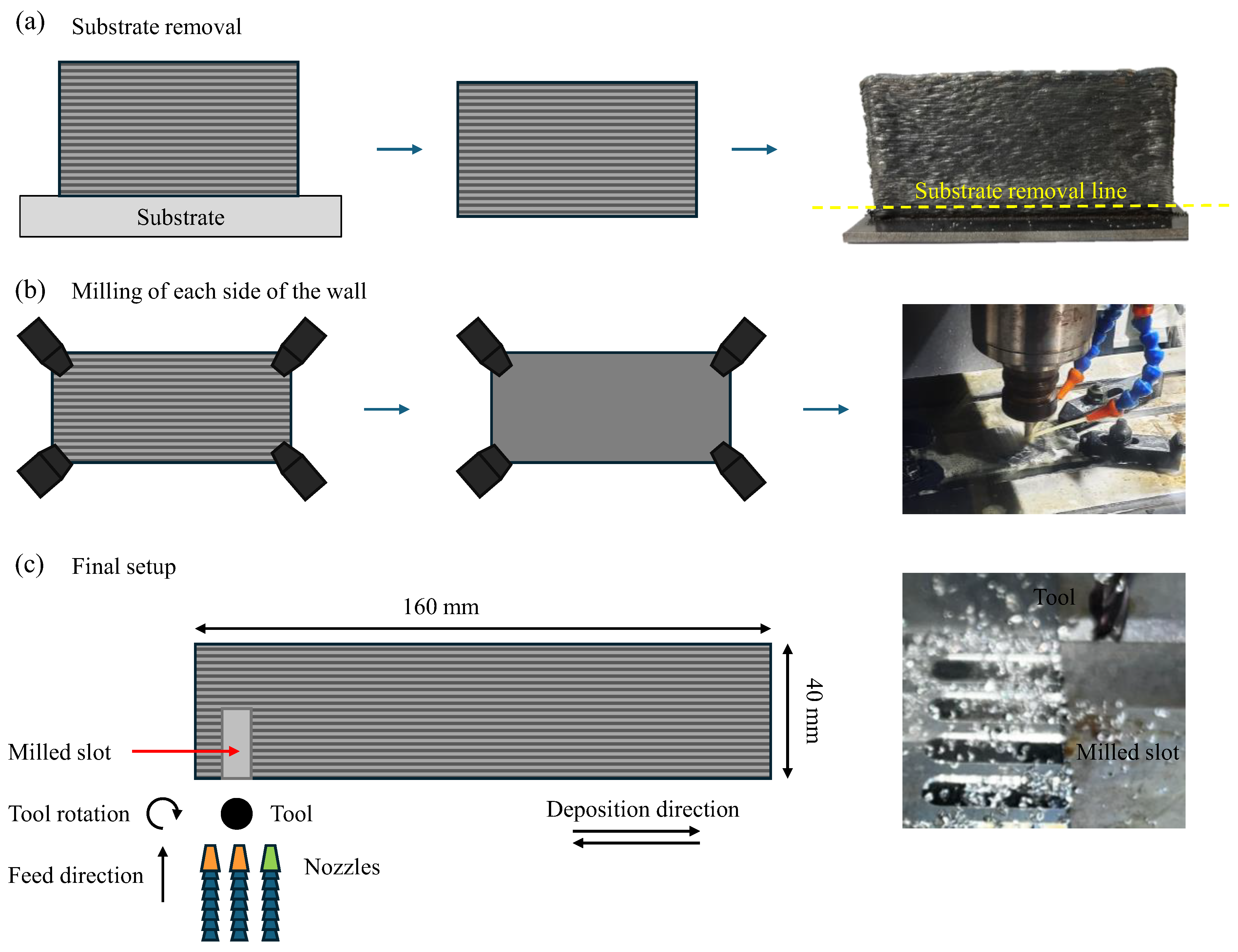
2.2. Material Deposition

To obtain the part studied in this work, the methodology proposed by Novelino et al. [65] was followed. In this sense, the selected equipment consisted of a Schneider Electric MAXR23-S42-H42-C42 Cartesian robot (manufacturer: Schneider Electric SE, Paris, France) and a Fronius TransPuls Synergic 5000 CMT power source (manufacturer: Fronius International GmbH, Pettenbach, Austria) configured for GMAW-CMT. It is worth highlighting that the CMT process was chosen because this method improves the quality of deposition as it allows for lower heat inputs and a greater control of the weld pool [65]. This work followed the parameters that resulted in the best geometry, obtained by Novelino et al. [65], which favored post-processing. These parameters included the use of a shielding gas composed of Ar + 18% CO2 and applied at 20 L/min flow, a current of 65 A, a torch travel speed (TTS) of 8 mm/s, a step-over of 1.2 mm, and a bidirectional deposition strategy (Figure 2a). When the heat input is calculated [66] for the conditions applied in this work, it yields approximately 0.125 kJ/mm, which, according to Fang et al. [67], falls within the optimal thermal input range for achieving controlled deposition while minimizing defects. Therefore, it was considered an intermediate value for this alloy.
A 100-layer wall was deposited, as can be observed in Figure 2b, with the deposition material being low-alloy steel ER70S-6, which contains 0.07% wt of C, 0.85% wt of Si, and 1.5% wt of Mn. The resulting microstructure is shown in Figure 2c and is similar to the one reported by Dekis et al. [68], characterized by a combination of acicular ferrite and polygonal ferrite. According to the authors, when depositing ER70S-6 it is also possible to observe pearlite along the primary ferrite grain boundaries. This type of microstructure is characteristic of low-alloy steels [69].
After deposition, the resulting wall had raw maximum dimensions of 85 mm in height, 7 mm in width, and 160 mm in length. To appropriately evaluate the influence of the cutting fluid it was necessary to prepare the part for the machining trials, as shown in Figure 3. The first step was removal of the substrate, as shown in Figure 3a. According to Prajadhiana et al. [70], this step is critical to the final component distortion and should be considered during the research to properly reflect the real-word application. The second step was the milling of the surface, Figure 3b, and this step was essential as WAAM-CMT-deposited walls can present dimensional variation, with the middle section of the wall having a lower width [65]. After the processing, the final sample dimensions were 40 in mm height, 5 mm in width, and 160 in mm length, with a resulting surface roughness of Ra ~ 3 µm. Figure 3c contains the scheme of the deposited wall indicating the deposition and machining directions.

2.3. Cutting Parameters

The machining trials occurred in a XH7132 CNC machine with a 3.7 kW spindle and a FANUC controller. The cutting tool was a TiAlN-coated carbide mill, model G9A69050, with four flutes, a 5 mm diameter, a cutting length of 16 mm, and a helix angle of 30°. All the cutting parameters were determined by preliminary trials, varying cutting speed from 10 m/min to 60 m/min and feed per tooth from 0.005 to 0.075 mm/tooth. The higher limits were defined by tool breakage or excessive sparking. Considering the surface quality objective, the combination that resulted in lower roughness values was selected and can be observed on Table 2. A new tool was used for each configuration. Although not the focus of the work, all tools were evaluated after machining to ensure they showed no breakage, damage, or excessive wear that could have influenced the surface quality.
As the objective of this research was to evaluate the influence of the cutting fluid on the cutting process, aiming to optimize the widely applied flood method, the following aspects were varied:
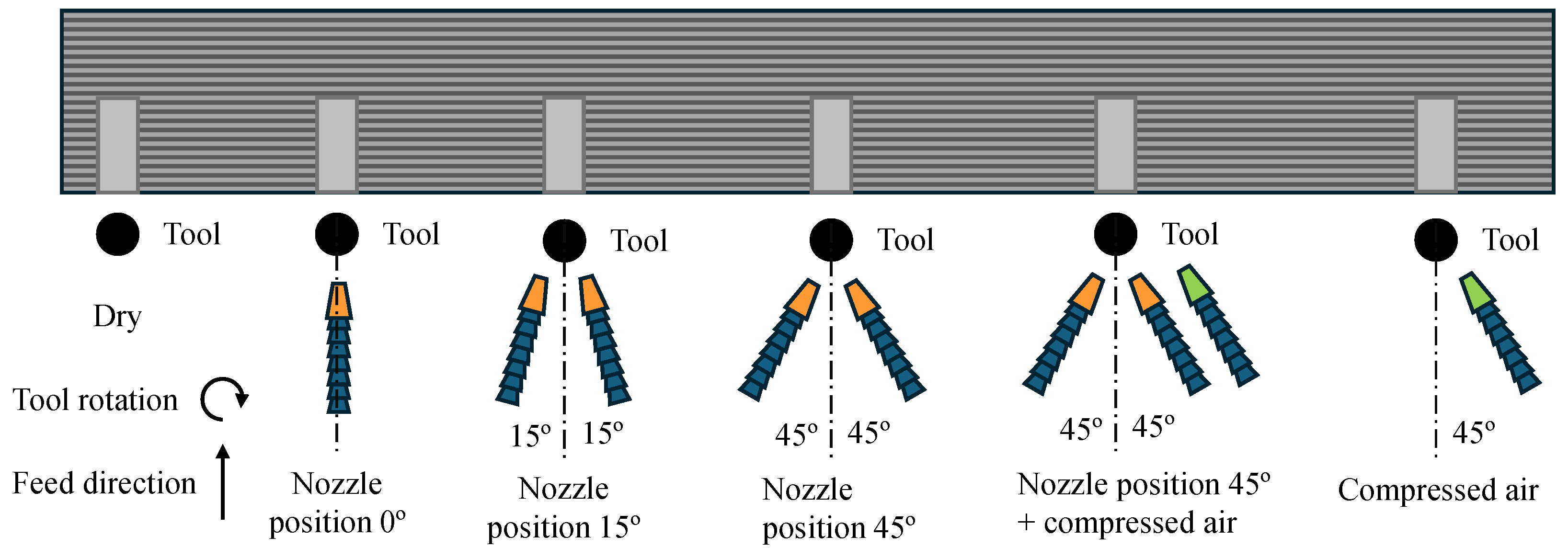
  • Number of nozzles: 0, 1, or 2 cutting fluid nozzles;
  • Positioning relative to the feed direction: 0°, 15°, and 45°;
  • Use of compressed air: with and without compressed air;
  • Flow rate (cutting fluid): 5 L/min, 10 L/min, and 20 L/min.
Considering that each nozzle could deliver a maximum of 10 L/min, the experimental design can be observed in Table 3. Compressed air (CA) was added to the flood method as an intermediate condition. Experiments with compressed air and dry cutting were also performed for comparison, as represented in Figure 4. The distance between the tip of the nozzles and the tool was maintained constant at 100 mm for all the configurations. This distance was selected due to the nozzle configuration on the CNC machine, to ensure consistent application angles. The cutting fluid was BIO 100e, manufactured by Biolub (Sorocaba, Brazil), which has a yellow-green visual aspect, a density of 1.065 g/cm3, a refractive index (MT 29) of 3.33, and a pH (3% in Water) of 9.5. It does not cause corrosion in Cast Iron Corrosion GG 25, 3% Solution (DIN 51.3560/2). This cutting fluid was selected for being biodegradable, enabling the use of flood while reducing the environmental impacts and treatment/disposal costs. It was diluted in water in a 1:10 ratio, as recommended by the manufacturer for flood. The air pressure on the compressed air nozzle was 0.6 MPa, resulting in an air flow rate of ~660 L/min.

2.4. Output Variables

The surface roughness was measured with a portable surface roughness tester, model SJ-201 from Mitutoyo (Kawasaki, Japan), with a Gaussian filter and an evaluation length (n) = 5. For each condition, three measurements were made. The results are presented as the mean values with two times the standard deviation, resulting in a confidence interval of 95%. The sampling size and confidence interval were based on machining literature. All the measurements were performed in a room with a controlled temperature of 20 ± 1 °C. To qualitatively evaluate the surface a microscope model LEXT OLS4100, manufactured by Olympus (Tokio, Japan) was used. The images obtained were treated on the Octave software, following the methodology proposed by Costa et al. [8] to enhance the visualization of surface details. In this process, the images were imported into the software, the pixels converted into a matrix, and then a numerical gray scale was attributed for each pixel. These were then converted into a colormap for plotting.
To obtain the surface hardness, a hardness tester model ZHU250 from the manufacturer Zwick Roell (Nagel, Germany), configured with a Brinell sphere, was used. For each condition, three measurements were performed. It is worth mentioning that the hardness was evaluated after all the other variables since it damages the surface. Finally, the results were statistically evaluated through an Analysis of Variance (ANOVA), and the main effects were calculated to better differentiate the cooling–lubrication conditions.

3. Results and Discussion

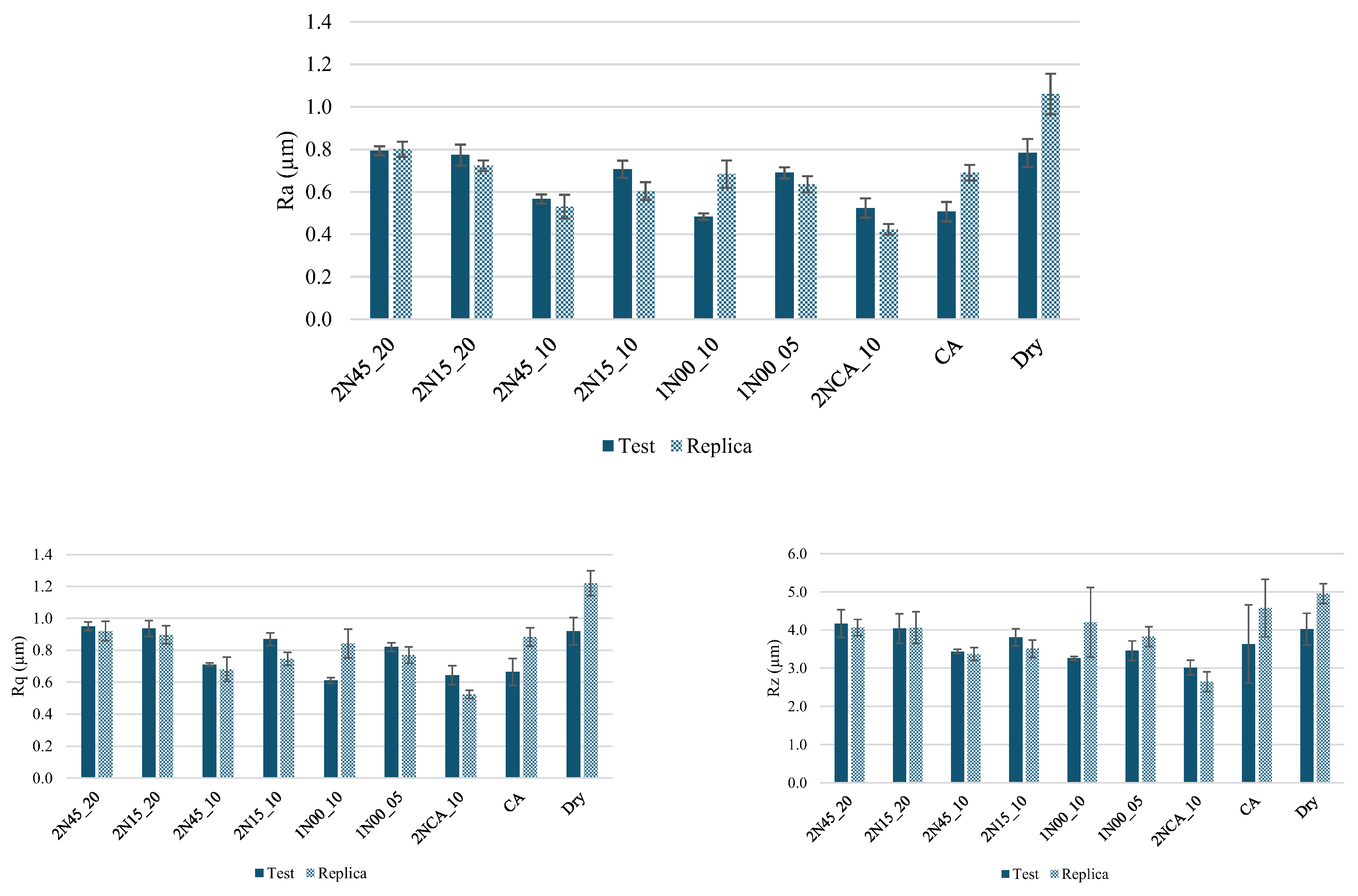
3.1. Surface Roughness

The roughness values for all the conditions evaluated can be observed in Figure 5. Regardless of the parameter observed, Ra, Rq, or Rz, it is possible to notice that the highest values were obtained for dry machining, which was expected: Ra = 1.06 µm for the replica. The higher flow rate, 20 L/min, presented the second (Ra = 0.80 µm) and third (Ra = 0.77 µm) highest values, for the positions of 45° and 15°, respectively, which agrees with the second hypothesis. Next, compressed air presented results comparable to 2NCA_10 and 1N00_10, where Ra equals to 0.51 µm, 0.48 µm, and 0.52 µm, respectively. The lowest value, Ra = 0.42 µm, was observed for the replica when machining with the combination of two nozzles and compressed air, which might be due to the compressed air enhancing the cutting fluid’s ability to reach the tool–chip interface, leading to better cooling–lubrication efficiency. The presence of compressed air could also improve the removal of chips from the cutting zone, avoiding chip recutting and contact with the machined surface.
Regardless of the method, apart from dry cutting, all conditions were able to achieve Ra values below 0.8 µm, consistent with those obtained by Chernovol et al. [25] in the tangential milling of a low-alloy steel manufactured by WAAM. The results were also coherent with those obtained by Li et al. [26] in a similar study on milling low-alloy steel manufactured by WAAM. The authors varied the feed per tooth to 0.03, 0.04, and 0.06 mm/tooth, resulting in Ra values of approximately 1.1 µm, 1.4 µm, and 1.5 µm, respectively.
Since there are many variables being observed, Figure 6 contains the roughness values plotted according to the main effects, where the low flow rate stands for 5 L/min, medium for 10 L/min, high for 20 L/min, and null for conditions without liquid cutting fluid. It was noted that the combination of two nozzles and compressed air stood out as it resulted in the lowest Ra, Rq, and Rz values, reaching approximately a 50% reduction when compared to dry cutting. Compressed air can also be highlighted as it achieved results comparable to the one-nozzle conditions and better results than two-nozzles conditions, which favors a smooth surface with Ra equal to 0.51 µm, without the need for flood cutting fluid. The use of compressed air led to a reduction in the roughness of approximately 36% in comparison to dry cutting.
Results from both Figure 5 and Figure 6 indicate that the optimal flow rate for this application is the medium flow of 10 L/min. When comparing the mean Ra by effect, the reduction in the flow rate from 20 L/min to 10 L/min improved the surface quality by approximately 30%, which was not expected since higher flow rates usually result in better surfaces when machining steels [71]. In fact, this result was unexpected and contradicted the first hypothesis, which stated that a higher flow rate can contribute to better surface finish, since according to machining literature the usual behavior is an increase in surface quality with fluid flow rate (for flood) [72].
However, in some applications there is an optimal flow rate point in which the Ra is minimized, as observed by Al-Saraireh et al. [73]. Thus, after this optimal point increasing the flow rate will result in an increase in the surface roughness, similar to what was observed in this work. With the increase from 5 L/min to 10 L/min there was a decrease in roughness; however, after this point, increasing to 20 L/min worsened the surface quality. Those results are partially aligned with the third hypothesis since compressed air had a superior finish when compared to dry cutting and an inferior one when compared to flood; nevertheless, it had lower Ra, Rq, and Rz values than the two-nozzles conditions, which was not expected. To better understand the impact of each cutting condition a one-way ANOVA was performed to analyze each individual factor, which is more adequate for the design of this work [74]. The p-value obtained from the respective ANOVA for Ra, Rq, and Rz can be observed in Table 4.
The nozzle position presented the least influence, as can be observed in Figure 6, since it only reduced the Ra by about 20% when using 45°. However, it was not statistically significant, with a p-value of 0.849; therefore, the reduction in Ra might be a result of the condition, since for two nozzles, for instance, it is not possible to position them at 0 degrees. Both the cutting condition and the flow rate were statistically significant factors affecting the roughness values.

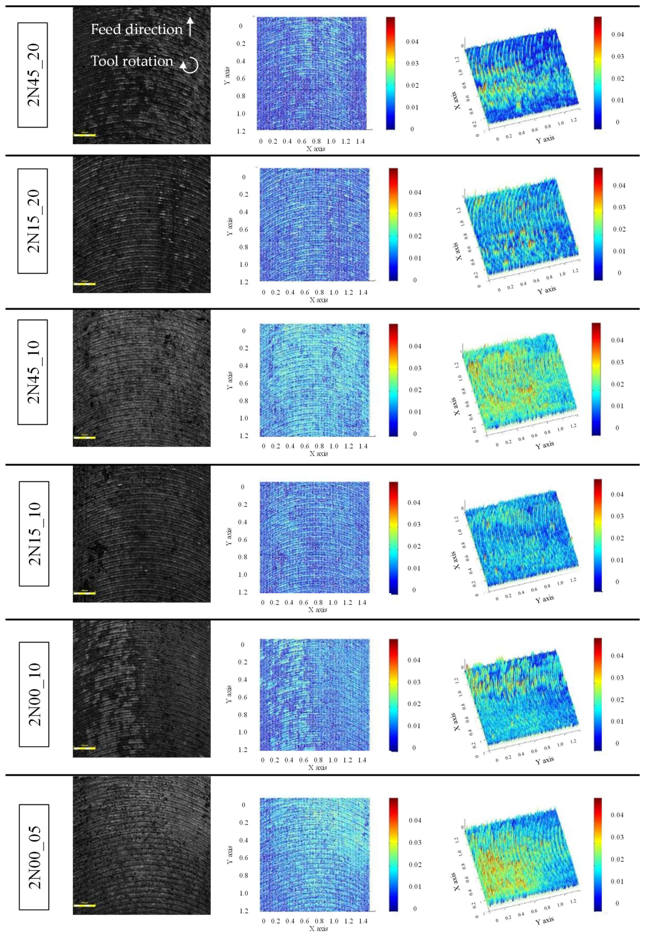
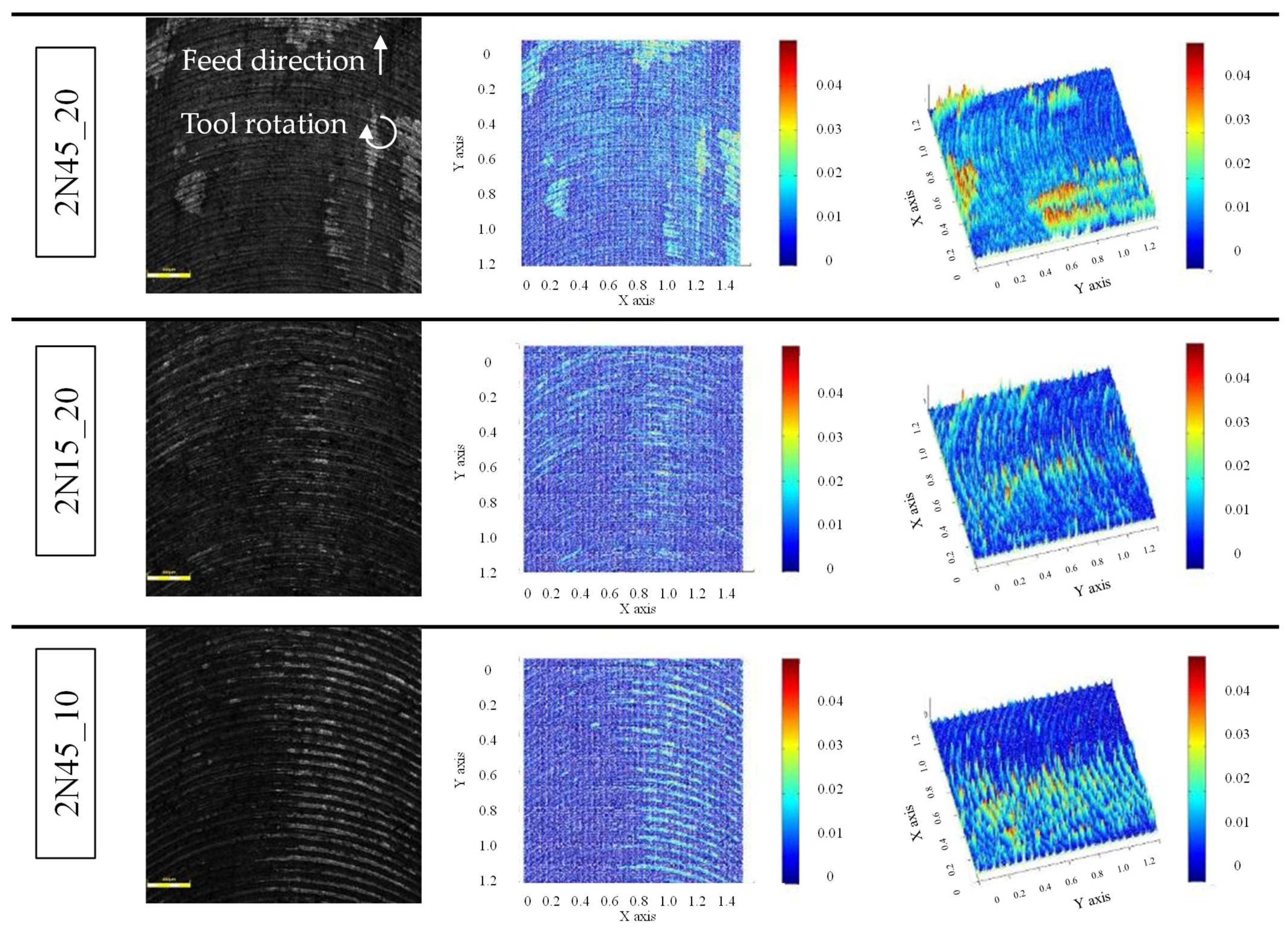
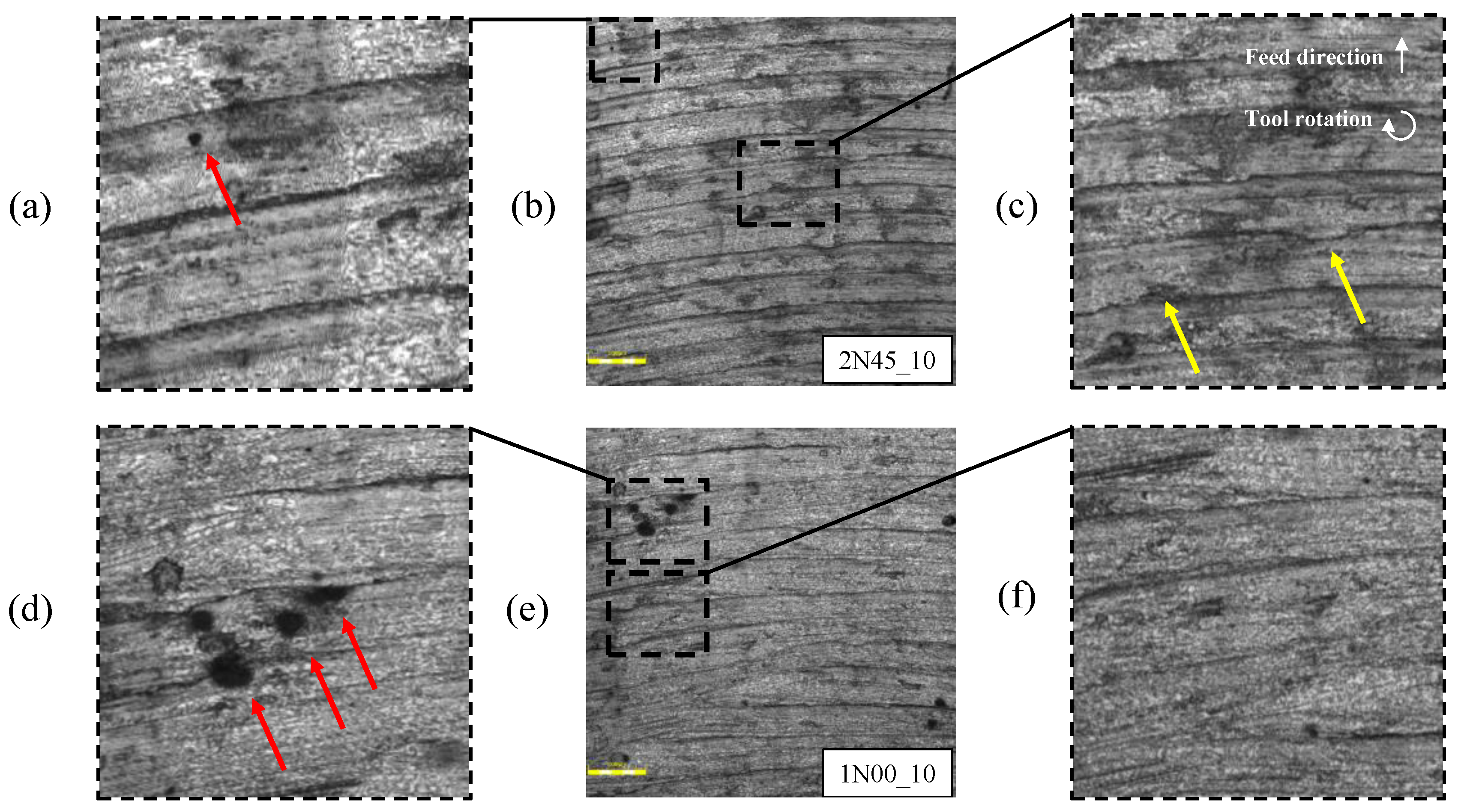
3.2. Surface Quality

To better comprehend the milled surface, apart from the roughness values, it is also important to observe it through microscopy. Figure 7 and Figure 8 contain not only the microscopy view of the surfaces but also the treated images to enhance the visibility of surface details. It is worth mentioning that the color scale was normalized for a better comparison between different conditions and therefore the z axis (color scale) is representative rather than an absolute value. Overall, the surfaces presented well-defined feed marks and color variation, which might be associated with the variations in the microstructure caused by the deposition. Therefore, the tridimensional representation of peaks for the lighter surfaces might not be truly associated with a geometrical variation during the cut but rather with this microstructure variation.
According to Das et al. [75], when ER70S-6 is deposited by WAAM it might possess significant microstructure variation, with more equiaxed grains near the substrate, followed by an intermediate region with equiaxed, dendritic, and columnar grains, exhibiting high microstructure variation and a top region with a predominance of dendritic grains. Considering that, in this study samples were machined from the side of a wall deposited by WAAM, and the machined region chosen was the intermediate section (of wall length) where high variation is expected.
The cooling–lubrication conditions with a flow rate of 10 L/min or lower were selected for a more detailed analysis, since not only do they result in better surface quality, but they are also more environmentally friendly, requiring less or no cutting fluid. In Figure 9 and Figure 10, higher magnification images of the selected conditions (2N45_10, 1N00_10, 2NCA_10, CA, and Dry) can be observed, showing details of the machined surface. In Figure 9a,d red arrows indicate potential pores, which, according to Dekis et al. [68], might occur during the deposition and are usually associated with the parameters applied. Considering the tool path, the porosity indicated is likely formed during the deposition rather than as a result of material detachment during the milling.
The 2N45_10 condition resulted in a surface with irregular feed marks, as seen in Figure 9c, with potential plowing indicated by the yellow arrows. In contrast, compared to 1N00_10, a condition with the same flow rate which only varied the number of nozzles and the position, it is not possible to clearly define the feed marks, as can be noted in Figure 9f, which also supports the second hypothesis. Feed marks are expected during the milling, and the absence of them might indicate that the cut is not being successfully achieved. Considering that the material has ductile characteristics, the surface in this case might have been subjected to high plastic deformation. On the other hand, despite the improper chip formation, this type of surface tends to be smooth, leading to low roughness values when measured.
Now observing the conditions with CA and dry cutting in Figure 10b,e,g, it is possible to notice that the cooling–lubrication condition led to distinct surface morphologies. The red arrows in Figure 10a,g might be associated with porosity, as mentioned above. The red arrow in Figure 10f,i, however, might indicate a detachment of harder or more brittle regions that occurred during machining. The dark marks in Figure 10g,i may resemble corrosion marks, however, this is unlikely to be actual corrosion since they appeared under dry cutting conditions. Moreover, previous research has shown that the deposited ER70S-6 exhibits better corrosion resistance than the wrought material [9]. Therefore, the observed marks are more likely related to the deposition process.
In Figure 10g, evidence of plowing, indicated by yellow arrows, can also be observed. The overall irregular surface was expected since this condition led to the highest roughness values, which is in agreement with the fourth hypothesis that stated that dry cutting will result in the worst surface quality. Another characteristic that can be observed in Figure 10c is the presence of linear marks on the surface, regardless of the tool path, indicated by the blue arrows. This phenomenon might also be associated with the deposition; however, it is important to note that the tool feed direction is perpendicular to the deposition direction. Therefore, these marks should not be associated with interlayer characteristics. A possible explanation for these perpendicular marks is the microstructural variation that can occur within the deposited part. Dekis et al. [68] mention that the microstructure changes with wall height due to different thermal loads. Notably, these authors deposited the same alloy, ER70S-6, using WAAM.

3.3. Surface Hardness

During machining, the surface hardness can vary due to the heat input and plastic deformation on the surface (i.e., work hardening). In Figure 11, the hardness values of the machined surfaces are plotted according to the main effects, and it is important to note that the mean surface hardness of the part before machining was 138.7 ± 0.62 HB. It is worth mentioning that machining experiments were carefully performed in the same region of the wall to avoid any interference from the hardness variation that can occur across the wall width [8]. Nonetheless, the hardness evaluation presented in this work is a comparative analysis of the cooling–lubrication impact relative to the hardness of the prepared surface. The conditions selected for the hardness evaluation were the ones selected for the detailed surface analysis: 2N45_10, 1N00_10, 2NCA_10, CA, and Dry. A one-way ANOVA was also conducted to evaluate the statistical significance of the factors affecting surface hardness; among the variables, only the test and condition had sufficient data for the analysis. The p-values obtained were 0.957 and 0.002 for the test and condition, respectively, indicating that only the condition had a statistically significant effect.
When low hardness variation is required, the 2NCA_10 condition stands out, showing a reduction of only 4.72%, followed by CA, with a 6.51% reduction. Dry cutting and 2N45_10 produced similar results, with reductions of 7.43% and 7.93%, respectively. The highest hardness variation occurred under the 1N00_10 condition, which showed a reduction of 8.51%. Regarding the flow rate, it is possible to notice that when analyzing the main effects conditions without a cutting fluid presented an overall better performance in terms of minimizing the hardness variation. The lower hardness variation observed for 2NCA_10 indicates that compressed air enhanced the cutting fluid’s effectiveness at the tool–chip interface, improving surface quality in terms of both roughness and hardness. This condition was followed by compressed air alone, which could achieve the second-lowest hardness variation and comparable roughness to the one-nozzle condition without the need for cutting fluid.
In grinding research, Krishnan Ramachandranar et al. [60] applied compressed air during the grinding of 316 steel deposited by WAAM and evaluated the influence of the grinding cooling–lubrication conditions on the fatigue life of the part. The authors observed that grinding increased the hardness of the part from 237 HV to 260 HV and 270 HV when using flooding and compressed air, respectively. They attributed the better performance of the air cooling compared to flood to the compressive residual stresses induced on the surface. Importantly, they also evaluated the fatigue life impact; for a stress amplitude of 117.45 MPa, a higher life was obtained by the conventional material, reaching 10,000,000 cycles. The second-best result was obtained with WAAM (air-cooled grinding), resulting in 1,139,000 cycles, followed by WAAM (flood-cooled grinding) with 940,000 cycles, while the lowest was observed for WAAM (untreated) with 380,000 cycles.
It is worth nothing that the thermal gradients during grinding are typically higher than in other conventional machining processes due to the intense friction that occurs in the abrasive grit–part interface [76]. Therefore, caution must be exercised when comparing these results to those of the present study as the underlying mechanisms may differ. On a study with defined cutting-edge machining, Hrechuk et al. [77] performed turning experiments on 316 steel alloy with different microstructures and a controlled atmosphere. The authors observed that the presence of oxygen enabled oxide formation, and that while increasing the oxidation wear mechanism the overall tool wear was reduced in the presence of oxides. This behavior was attributed to improved tribological conditions, which were able to suppress other wear mechanisms. Therefore, the performance of compressed air observed in this work may be linked to increased oxidation at the tool–chip interface. Although oxidation is usually considered unwanted, it can contribute positively to the tribological behavior. It is suggested that future studies should explore the use of controlled atmospheres without oxygen to further investigate the influence of oxide formation during the machining of WAAM steels.

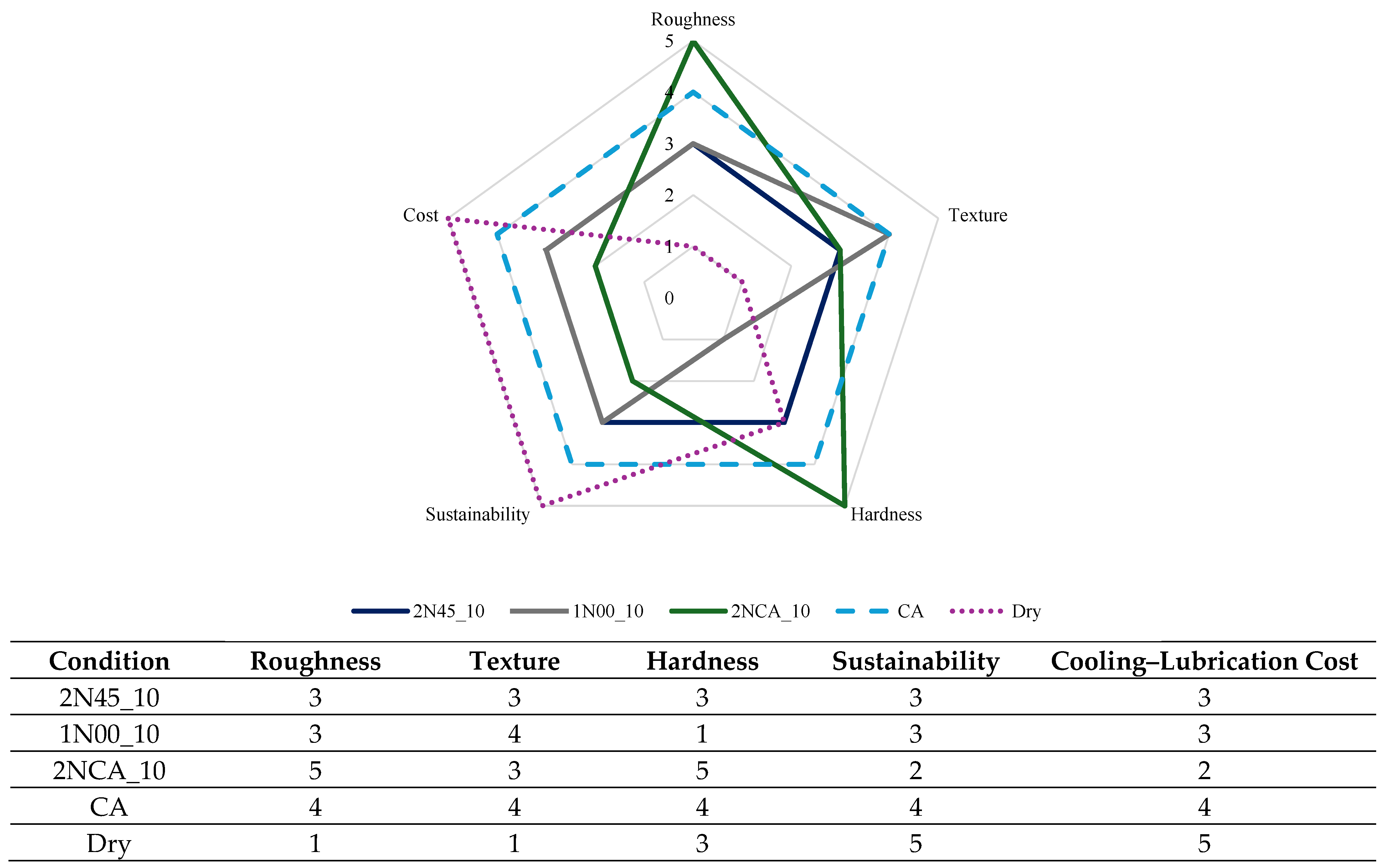
3.4. Overall Analysis

Synthesizing the various results reveals that compressed air had a positive influence on the process, with the 2NCA_10 condition outperforming all other two-nozzles configurations. Similarly, in the absence of cutting fluid, the CA condition delivered higher surface quality than dry cutting. These improvements associated with compressed air may have occurred for the following distinct reasons:
  • The mechanical action of the air pressure on the chips, which may have facilitated chip breakage.
  • Enhanced chip evacuation from the cutting zone, reducing recutting and surface damage.
  • The cooling effect from air flow, which may have limited thermal damages.
  • Improved fluid penetration when combined with cutting fluid, enabling the cutting fluid to further reach the cutting zone.
Therefore, evaluating distinct factors is essential when selecting a cooling–lubricant strategy for machining new materials. The overall impact on production must also be considered. In this context, Figure 12 presents a qualitative evaluation using a five-point scale, where five represents the highest (or most favorable) rating. The criteria “Roughness” and “Hardness” were based on the values presented in this study. The authors rated “Texture” qualitatively through microscopy, as detailed in Section 3.2.
“Sustainability” was evaluated following the methodology of Benedicto et al. [78]. Dry cutting received the highest rating (5) due to the absence of any input requirements. Compressed air was rated 4, accounting for the energy consumption of the compressor. Conditions involving cutting fluid were rated as 3, as they require fluid input, water, and pump power. The combination of cutting fluid and compressed air received a rating of 2 due to the cumulative input and energy demand of both systems. Lastly, “Cooling–Lubrication cost” was assessed considering energy consumption and material inputs, yielding a classification similar to “Sustainability”. It is important to note that this cost does not account for the impact on tool wear.
Dry cutting inherently offers a relative sustainability advantage as it requires no additional inputs. However, it can be effectively replaced by the CA condition, which demonstrated one of the lowest Ra values (0.51 µm), minimal surface defects under microscopy, and the second-lowest hardness reduction. It is worth nothing that most commercial CNC machines are already equipped with a compressed air supply for standard operation, as was the case in this study. Therefore, compressed air is readily available for industrial use, with increased compressor energy consumption being its primary drawback. This aligns with the conclusions of Singh et al. [79], who emphasize sustainability as a central challenge in additive manufacturing and underscore the importance of adopting feasible, resource-efficient strategies, such as those proposed in this work for post-processing.
The use of cutting fluid, although adding cost and reducing sustainability, can be improved by using eco-friendly oils like the one used in this study. Another crucial factor is the careful evaluation of the delivery method, specifically the nozzle positioning and flow rate as these parameters significantly influence the outcomes. For example, combining compressed air with the cutting fluid resulted in better roughness and hardness values. Notably, traditional flood, even with different configurations, did not outperform the CA condition in terms of surface quality.

4. Conclusions

After the machining ER70S-6 steel was deposited by WAAM-CMT under different cooling–lubrication conditions and the surface quality was evaluated, the following conclusions were drawn:
  • Among the conditions tested, a flow rate of 10 L/min stood out by achieving a lower roughness value (Ra = 0.48 µm) compared to 0.69 µm at 5 L/min, partially confirming the first hypothesis. The lower Ra at 20 L/min was 0.77 µm, indicating the presence of an optimal flow rate.
  • In agreement with second hypothesis, varying the nozzle position improved the surface quality without adding extra costs or resources. For 20 L/min the Ra varied from 0.79 µm at 45° to 0.77 µm at 15°, and at 10 L/min it varied from 0.71 µm with two nozzles at 15° to 0.48 µm with one-nozzle at 0°.
  • Compressed air delivered better surface finish than dry cutting, but it was generally inferior to flood cooling, though not for all configurations. This partially confirms the third hypothesis.
  • Dry cut, while the most environmentally friendly, failed to achieve a satisfactory surface quality for the ER70S-6 WAAM-CMT, resulting in Ra = 0.78 µm, Rq = 0.92 µm, and Rz = 4.02 µm. The inferior results support the fourth hypothesis.
  • The combination of compressed air and cutting fluid improved surface quality by 50% compared to dry cutting and also led to the lowest hardness variation (4.72%).
Using only compressed air achieved a favorable balance of low roughness (Ra of 0.51 µm), good surface texture (qualitative evaluated through microscopy), and acceptable hardness deviation (6.51%). Thus, CA is a viable, more sustainable alternative to flood for milling WAAM steels, eliminating the need for a cutting fluid. This work focused on the ER70S-6 alloy and the milling under fixed cutting parameters with no tool variation, contributing valuable data to the relatively sparse literature on machining of WAAM alloys. However, many aspects remain to be explored, such as different alloys, deposition methods, and parameters influencing machinability, in addition to variations in cutting parameters, cutting tools, tool coatings, etc. Future research directions based on this work include the following:
  • Comparing the tool wear rates and mechanisms under the cooling–lubrication conditions studied to evaluate tool life and costs.
  • Investigating the effect of microstructural variation on surface finishing after milling.
  • Testing a wide range of flow rates to determine the optimal value.
  • Performing machining in controlled atmospheres to study oxidation effects.
  • Conducting power analysis to access minimum sample sizes for roughness and hardness measurements.
  • Quantifying energy consumption and associated CO2 emissions for each cooling–lubrication condition to deepen sustainability assessments.

Author Contributions

Writing—original draft preparation: D.d.O., L.R. and T.S. Investigation: M.V.G., G.M.R. and A.L.S.d.C. Data curation: M.V.G., G.M.R. and A.L.S.d.C. Methodology: D.d.O. and M.Z. Validation: D.d.O., A.d.J., L.M. and M.Z. Writing—review and editing: D.d.O. Supervision: D.d.O., L.M. and M.Z. All authors have read and agreed to the published version of the manuscript.

Funding

The authors are grateful to CNPq, grant numbers 405499/2022-1, 402730/2023-2, 443148/2023-6, and 200018/2025-6 for financial support.

Data Availability Statement

All data supporting the findings of this study are in the manuscript. Additional data are available from the corresponding author upon reasonable request.

Acknowledgments

The authors are grateful to their institutions, University of Brasilia and INEGI. The authors are also grateful to Brazilian funding agencies (Brazilian Federal Agency for Support and Evaluation of Graduate Education) CAPES and the National Council for Scientific and Technological Development (CNPq). The authors acknowledge LAETA/INEGI—Associate Laboratory of Energy, Transports and Aerospace/Institute of Science and Innovation in Mechanical Engineering and Industrial Engineering.

Conflicts of Interest

The authors have no competing interests to declare which are relevant to the content of this article.

References

  1. Shah, A.; Aliyev, R.; Zeidler, H.; Krinke, S. A Review of the Recent Developments and Challenges in Wire Arc Additive Manufacturing (WAAM) Process. J. Manuf. Mater. Process. 2023, 7, 97. [Google Scholar] [CrossRef]
  2. Singh, C.P.; Sarma, R.; Rajput, A.S.; Kapil, S. A nature-inspired build strategy for consistently fabricating intricate objects by wire-arc-based directed energy deposition. Prog. Addit. Manuf. 2024. [Google Scholar] [CrossRef]
  3. de Araújo Soares, M.A.; Novelino, A.L.B.; Ziberov, M. Geometry Study on 410NiMo Alloy Parts Printed by WAAM-CMT; Springer: Berlin/Heidelberg, Germany, 2024; pp. 114–125. [Google Scholar] [CrossRef]
  4. Gupta, D.K.; Mulik, R.S. Numerical simulation and experimental investigation of temperature distribution during the wire arc additive manufacturing (WAAM) process. Prog. Addit. Manuf. 2024, 10, 631–645. [Google Scholar] [CrossRef]
  5. Polamuri, S.K.; Chitral, S.; Adapa, M.K.; Nayak, A.; Kiran, D.V. A strategic approach to minimize lack of fusion defects in wire arc additive manufacturing. Prog. Addit. Manuf. 2025. [Google Scholar] [CrossRef]
  6. de Melo Vieira, M.; Liskevych, O.; de Oliveira, D.; Ziberov, M. Influence of parameter variation and interlayer temperature control in wall angle, curvature and measurement methodology of ER70S-6 parts obtained by WAAM. Manuf. Lett. 2024, 42, 40–45. [Google Scholar] [CrossRef]
  7. Zhai, W.; Wu, N.; Zhou, W. Effect of Interpass Temperature on Wire Arc Additive Manufacturing Using High-Strength Metal-Cored Wire. Metals 2022, 12, 212. [Google Scholar] [CrossRef]
  8. da Costa, A.L.S.; de Paiva, R.L.; de Oliveira, D.; Ziberov, M. Influence of Interlayer Temperature and Deposition Method on the Wall Geometry and Vickers Microhardness Profile of ER70S-6 Parts Manufactured by Additive Manufacturing Using CMT. J. Manuf. Mater. Process. 2025, 9, 93. [Google Scholar] [CrossRef]
  9. Ermakova, A.; Ganguly, S.; Razavi, N.; Berto, F.; Mehmanparast, A. Corrosion-fatigue crack growth behaviour of wire arc additively manufactured ER70S-6 steel parts in marine environments. Eur. J. Mech. A/Solids 2022, 96, 104739. [Google Scholar] [CrossRef]
  10. Barroqueiro, B.; Andrade-Campos, A.; Valente, R.A.F.; Neto, V. Metal Additive Manufacturing Cycle in Aerospace Industry: A Comprehensive Review. J. Manuf. Mater. Process. 2019, 3, 52. [Google Scholar] [CrossRef]
  11. Veer, P.; Mudakavi, D.; MAdinarayanappa, S. Optimizing multi-physics variables in wire arc additive manufacturing for weld bead aspect ratio: A machine learning approach. Prog. Addit. Manuf. 2025. [Google Scholar] [CrossRef]
  12. da Silva, C.P.; Silva, G.P.; Santos, M.C.; Ziberov, M.; Malcher, L. Hybrid search methodology for mechanical characterization of material produced via WAAM assuming Gurson porous material. J. Braz. Soc. Mech. Sci. Eng. 2024, 46, 266. [Google Scholar] [CrossRef]
  13. Dhinakaran, V.; Ajith, J.; Fathima Yasin Fahmidha, A.; Jagadeesha, T.; Sathish, T.; Stalin, B. Wire Arc Additive Manufacturing (WAAM) process of nickel based superalloys—A review. Mater. Today Proc. 2020, 21, 920–925. [Google Scholar] [CrossRef]
  14. Kah, P. Gas metal arc welding. In Advancements in Intelligent Gas Metal Arc Welding Systems; Elsevier: Amsterdam, The Netherlands, 2021; pp. 1–103. [Google Scholar] [CrossRef]
  15. Ola, O.T.; Doern, F.E. A study of cold metal transfer clads in nickel-base INCONEL 718 superalloy. Mater. Des. 2014, 57, 51–59. [Google Scholar] [CrossRef]
  16. Nagasai, B.P.; Malarvizhi, S.; Balasubramanian, V. Effect of welding processes on mechanical and metallurgical characteristics of carbon steel cylindrical components made by wire arc additive manufacturing (WAAM) technique. CIRP J. Manuf. Sci. Technol. 2022, 36, 100–116. [Google Scholar] [CrossRef]
  17. Norrish, J.; Polden, J.; Richardson, I. A review of wire arc additive manufacturing: Development, principles, process physics, implementation and current status. J. Phys. D Appl. Phys. 2021, 54, 473001. [Google Scholar] [CrossRef]
  18. Murugan, R.S.; Vinodh, S. Holistic review on design for additive manufacturing. Prog. Addit. Manuf. 2024. [Google Scholar] [CrossRef]
  19. Araujo, L.C.; de Almeida Ferreira, J.L.; Ziberov, M.; Araújo, J.A. Assessing Fatigue in Materials with Small Defects: A New Multiaxial Model Based on Principal Stress Amplitudes. Procedia Struct. Integr. 2024, 57, 144–151. [Google Scholar] [CrossRef]
  20. Ednie, L.; Lancaster, R.J.; Antonysamy, A.A.; Zelenka, F.; Scarpellini, A.; Parimi, L.; Maddalena, R.; Barnard, N.; Efthymiadis, P. The effects of surface finish on the fatigue performance of electron beam melted Ti–6Al–4V. Mater. Sci. Eng. A 2022, 857, 144050. [Google Scholar] [CrossRef]
  21. du Plessis, A.; Broeckhoven, C.; Yadroitsava, I.; Yadroitsev, I.; Hands, C.H.; Kunju, R.; Bhate, D. Beautiful and Functional: A Review of Biomimetic Design in Additive Manufacturing. Addit. Manuf. 2019, 27, 408–427. [Google Scholar] [CrossRef]
  22. De Oliveira, D.; Gomes, M.C.; Dos Santos, A.G.; Ribeiro, K.S.B.; Vasques, I.J.; Coelho, R.T.; Da Silva, M.B.; Hung, N.W. Abrasive and non-conventional post-processing techniques to improve surface finish of additively manufactured metals: A review. Prog. Addit. Manuf. 2023, 8, 223–240. [Google Scholar] [CrossRef]
  23. Gomes, M.C.; dos Santos, A.G.; de Oliveira, D.; Figueiredo, G.V.; Ribeiro, K.S.B.; De Los Rios, G.A.B.; da Silva, M.B.; Coelho, R.T.; Hung, W.N.P. Micro-machining of additively manufactured metals: A review. Int. J. Adv. Manuf. Technol. 2022, 118, 2059–2078. [Google Scholar] [CrossRef]
  24. Fuchs, C.; Baier, D.; Semm, T.; Zaeh, M.F. Determining the machining allowance for WAAM parts. Prod. Eng. 2020, 14, 629–637. [Google Scholar] [CrossRef]
  25. Chernovol, N.; Sharma, A.; Tjahjowidodo, T.; Lauwers, B.; Van Rymenant, P. Machinability of wire and arc additive manufactured components. CIRP J. Manuf. Sci. Technol. 2021, 35, 379–389. [Google Scholar] [CrossRef]
  26. Li, B.; Nagaraja, K.M.; Zhang, R.; Malik, A.; Lu, H.; Li, W. Integrating robotic wire arc additive manufacturing and machining: Hybrid WAAM machining. Int. J. Adv. Manuf. Technol. 2023, 129, 3247–3259. [Google Scholar] [CrossRef]
  27. Kocaman, E.; Köklü, U.; Morkavuk, S.; Coşkun, M.; Koçar, O.; Dilibal, S.; Gürol, U. Comparison of the mechanical properties and drilling performance of the AISI 316 parts produced with casting, LPBF and WAAM. J. Braz. Soc. Mech. Sci. Eng. 2024, 46, 728. [Google Scholar] [CrossRef]
  28. Vats, P.; Khanna, N.; Kumar, A.; Gajrani, K.K. Tribological performance of hBN and graphene-enriched hybrid nanofluids on tool wear and hole surface quality in drilling: A comparative study on WAAM and wrought Inconel 625. Wear 2025, 574–575, 206090. [Google Scholar] [CrossRef]
  29. Alonso, U.; Veiga, F.; Suárez, A.; Artaza, T. Experimental Investigation of the Influence of Wire Arc Additive Manufacturing on the Machinability of Titanium Parts. Metals 2020, 10, 24. [Google Scholar] [CrossRef]
  30. Ceritbinmez, F.; Günen, A.; Gürol, U.; Çam, G. A comparative study on drillability of Inconel 625 alloy fabricated by wire arc additive manufacturing. J. Manuf. Process 2023, 89, 150–169. [Google Scholar] [CrossRef]
  31. Khanna, N.; Patel, D.; Raval, P.; Airao, J.; Badheka, V.; Rahman Rashid, R.A. Comparison of sustainable cooling/lubrication strategies for drilling of wire arc additively manufactured Inconel 625. Tribol. Int. 2024, 200, 110068. [Google Scholar] [CrossRef]
  32. Martyushev, N.; Kozlov, V.; Boltrushevich, A.; Kuznetsova, Y.; Bovkun, A. Milling of Inconel 625 blanks fabricated by wire arc additive manufacturing (WAAM). Met. Work. Mater. Sci. 2025, 27, 61–76. [Google Scholar] [CrossRef]
  33. Fuchs, C.; Fritz, C.; Zaeh, M.F. Impact of wire and arc additively manufactured workpiece geometry on the milling process. Prod. Eng. 2023, 17, 415–424. [Google Scholar] [CrossRef]
  34. Lopes, J.G.; Machado, C.M.; Duarte, V.R.; Rodrigues, T.A.; Santos, T.G.; Oliveira, J.P. Effect of milling parameters on HSLA steel parts produced by Wire and Arc Additive Manufacturing (WAAM). J. Manuf. Process. 2020, 59, 739–749. [Google Scholar] [CrossRef]
  35. Vozar, M.; Jurina, F.; Vopat, T. Cutting Tool Design for Milling of Thin-Walled Inconel 718 Components Made by Waam. MM Sci. J. 2024, 2024, 7373–7379. [Google Scholar] [CrossRef]
  36. Gil Del Val, A.; Cearsolo, X.; Suarez, A.; Veiga, F.; Altuna, I.; Ortiz, M. Machinability characterization in end milling of Invar 36 fabricated by wire arc additive manufacturing. J. Mater. Res. Technol. 2023, 23, 300–315. [Google Scholar] [CrossRef]
  37. Laue, R.; Colditz, P.; Möckel, M.; Awiszus, B. Study on the Milling of Additive Manufactured Components. Metals 2022, 12, 1167. [Google Scholar] [CrossRef]
  38. Tian, H.; Lu, Z.; Chen, S. Predictive Modeling of Thermally Assisted Machining and Simulation Based on RSM after WAAM. Metals 2022, 12, 691. [Google Scholar] [CrossRef]
  39. Hu, S.; Wang, K.; Li, X.; Du, W.; Liu, M.; Qi, J. Development and Experimental Validation of a Hybrid Wire Arc Additive Manufacturing and Milling Repair Platform. Int. J. Precis. Eng. Manuf. 2025. [Google Scholar] [CrossRef]
  40. Sivakumar, M.; Shriram, S.; Jerald, J.; Prabakaran, R. Micro-milling performance and surface quality of wire arc additive manufactured P91 steel. Prog. Addit. Manuf. 2025. [Google Scholar] [CrossRef]
  41. Sommer, K.; Pfennig, A.; Sammler, F.; Abdelmoula, M.; Kamerer, D.; Heiler, R. First Approach in Analysis of Tool Wear When Milling Additive Manufacturing (AM) Parts. Appl. Sci. 2024, 14, 6219. [Google Scholar] [CrossRef]
  42. Zhang, S.; Zhang, Y.; Gao, M.; Wang, F.; Li, Q.; Zeng, X. Effects of milling thickness on wire deposition accuracy of hybrid additive/subtractive manufacturing. Sci. Technol. Weld. Join. 2019, 24, 375–381. [Google Scholar] [CrossRef]
  43. Dugar, J.; Ikram, A.; Klobčar, D.; Pušavec, F. Sustainable Hybrid Manufacturing of AlSi5 Alloy Turbine Blade Prototype by Robotic Direct Energy Layered Deposition and Subsequent Milling: An Alternative to Selective Laser Melting? Materials 2022, 15, 8631. [Google Scholar] [CrossRef] [PubMed]
  44. Wandtke, K.; Becker, A.; Schroepfer, D.; Kromm, A.; Kannengiesser, T.; Scharf-Wildenhain, R.; Haelsig, A.; Hensel, J. Residual Stress Evolution during Slot Milling for Repair Welding and Wire Arc Additive Manufacturing of High-Strength Steel Components. Metals 2024, 14, 82. [Google Scholar] [CrossRef]
  45. Fuchs, C.; Elitzer, D.; Höppel, H.W.; Göken, M.; Zaeh, M.F. Investigation into the influence of the interlayer temperature on machinability and microstructure of additively manufactured Ti-6Al-4V. Prod. Eng. 2023, 17, 703–714. [Google Scholar] [CrossRef]
  46. Zhang, S.; Gong, M.; Zeng, X.; Gao, M. Residual stress and tensile anisotropy of hybrid wire arc additive-milling subtractive manufacturing. J. Mater. Process Technol. 2021, 293, 117077. [Google Scholar] [CrossRef]
  47. Chen, C.; Feng, T.; Zhang, Y.; Ren, B.; Hao wang Zhao, X. Improvement of microstructure and mechanical properties of TC4 titanium alloy GTAW based wire arc additive manufacturing by using interpass milling. J. Mater. Res. Technol. 2023, 27, 1428–1445. [Google Scholar] [CrossRef]
  48. Li, F.; Chen, S.; Shi, J.; Tian, H.; Zhao, Y. Evaluation and Optimization of a Hybrid Manufacturing Process Combining Wire Arc Additive Manufacturing with Milling for the Fabrication of Stiffened Panels. Appl. Sci. 2017, 7, 1233. [Google Scholar] [CrossRef]
  49. Hendrickson, N.; Valizadeh Sotubadi, S.; Nguyen, V. Improving the Efficiency of WAAM-Based Hybrid Manufacturing Through Selective In-Situ Machining Based on Height Error Prediction. In Proceedings of the ASME 2024 19th International Manufacturing Science and Engineering Conference, Knoxville, TN, USA, 17–21 June 2024. Volume 1: Additive Manufacturing; Advanced Materials Manufacturing; Biomanufacturing; Life Cycle Engineering. [Google Scholar] [CrossRef]
  50. dos Santos, G.Q.V.; Kaneko, J.; Abe, T. Study on the Effects of Different Cutting Angles on the End-Milling of Wire and Arc Additive Manufacturing Inconel 718 Workpieces. Materials 2022, 15, 2190. [Google Scholar] [CrossRef]
  51. Yan, Z.; Ren, X.; Zhao, H.; Chen, S. Investigating the Impact of Robotic Milling Parameters on the Surface Roughness of Al-Alloy Fabricated by Wire Arc Additive Manufacturing. Materials 2024, 17, 4845. [Google Scholar] [CrossRef]
  52. Ozaner, O.C.; Klobčar, D.; Sharma, A. Machining Strategy Determination for Single- and Multi-Material Wire and Arc Additive Manufactured Thin-Walled Parts. Materials 2023, 16, 2055. [Google Scholar] [CrossRef]
  53. Alonso, U.; Veiga, F.; Suárez, A.; Gil Del Val, A. Characterization of Inconel 718® superalloy fabricated by wire Arc Additive Manufacturing: Effect on mechanical properties and machinability. J. Mater. Res. Technol. 2021, 14, 2665–2676. [Google Scholar] [CrossRef]
  54. Montevecchi, F.; Grossi, N.; Takagi, H.; Scippa, A.; Sasahara, H.; Campatelli, G. Cutting Forces Analysis in Additive Manufactured AISI H13 Alloy. Procedia CIRP 2016, 46, 476–479. [Google Scholar] [CrossRef]
  55. Kokare, S.; Oliveira, J.P.; Santos, T.G.; Godina, R. Environmental and economic assessment of a steel wall fabricated by wire-based directed energy deposition. Addit. Manuf. 2023, 61, 103316. [Google Scholar] [CrossRef]
  56. Li, B.; Zhang, X.; Li, W. Exploratory study of repairing damaged aluminum part through robotic hybrid wire arc additive manufacturing and machining for potential in-space manufacturing. Int. J. Adv. Manuf. Technol. 2024, 135, 3101–3112. [Google Scholar] [CrossRef]
  57. Quadra Vieira dos Santos, G.; Kaneko, J.; Abe, T. Analysis of Machinability on Properties of Inconel 718 Wire and Arc Additive Manufacturing Products. J. Manuf. Mater. Process. 2023, 8, 4. [Google Scholar] [CrossRef]
  58. Quadra Vieira dos Santos, G.; Kaneko, J.; Abe, T. Analysis of Heat Treatment and Its Effects on the Machinability of Inconel 718 Products Manufactured with Wire and Arc Additive Manufacturing Technique. J. Mater. Eng. Perform. 2024. [Google Scholar] [CrossRef]
  59. Karlina, A.I.; Kondratyev, V.V.; Balanovskiy, A.E.; Astafyeva, N.A.; Yamshchikova, E.A. Porosity reduction in metal with hybrid wire and arc additive manufacturing technology (WAAM). CIS Iron Steel Rev. 2024, 27, 91–95. [Google Scholar] [CrossRef]
  60. Ramachandran, M.K.; Sumaiya, S.A.; Golvaskar, M.; Wood, J.; Sluder, I.; Rakurty, C.S.; Rangasamy, N.; Emuakpor, O.S.; Kannan, M. Improving the Fatigue Life of an Additively Manufactured Stainless-Steel Specimen Using a Secondary Grinding Process. In Proceedings of the ASME Turbo Expo 2024: Turbomachinery Technical Conference and Exposition, London, UK, 24–28 June 2024. Volume 9: Manufacturing Materials and Metallurgy; Microturbines, Turbochargers, and Small Turbomachines; Oil & Gas Applications; Steam Turbine. [Google Scholar] [CrossRef]
  61. Alimuzzaman, S.M.; Jahan, M.P.; Rakurty, C.S.; Rangasamy, N.; Ma, J. Cutting fluids in metal AM: A review of sustainability and efficiency. J. Manuf. Process 2023, 106, 51–87. [Google Scholar] [CrossRef]
  62. Gan, C.K.; Liew, P.J.; Leong, K.Y.; Yan, J. Biodegradable cutting fluids for sustainable manufacturing: A review of machining mechanisms and performance. Int. J. Adv. Manuf. Technol. 2024, 131, 955–975. [Google Scholar] [CrossRef]
  63. de Oliveira, D.; de Paiva, R.L.; de Souza Ruzzi, R.; Jackson, M.J.; Gelamo, R.V.; Machado, A.R.; da Silva, R.B. A comprehensive evaluation of the use of graphene enriched cutting fluids on the surface integrity of very poor-grindability materials. Wear, 2025; in press. [Google Scholar] [CrossRef]
  64. Madanchi, N.; Winter, M.; Thiede, S.; Herrmann, C. Energy Efficient Cutting Fluid Supply: The Impact of Nozzle Design. Procedia CIRP 2017, 61, 564–569. [Google Scholar] [CrossRef]
  65. Novelino, A.L.B.; Carvalho, G.C.; Ziberov, M. Influence of WAAM-CMT deposition parameters on wall geometry. Adv. Ind. Manuf. Eng. 2022, 5, 100105. [Google Scholar] [CrossRef]
  66. Zeng, J.; Nie, W.; Li, X. The Influence of Heat Input on the Surface Quality of Wire and Arc Additive Manufacturing. Appl. Sci. 2021, 11, 10201. [Google Scholar] [CrossRef]
  67. Fang, Q.; Zhao, L.; Chen, C.; Zhu, Y.; Peng, Y.; Yin, F. Effect of heat input on microstructural and mechanical properties of high strength low alloy steel block parts fabricated by wire arc additive manufacturing. Mater. Today Commun. 2023, 34, 105146. [Google Scholar] [CrossRef]
  68. Dekis, M.; Tawfik, M.; Egiza, M.; Dewidar, M. Unveiling the Characteristics of ER70S-6 low Carbon Steel Alloy Produced by wire arc Additive Manufacturing at Different Travel Speeds. Met. Mater. Int. 2024, 31, 325–338. [Google Scholar] [CrossRef]
  69. Ghosh, P.K.; Gupta, S.R.; Randhawa, H.S. Characteristics of a Pulsed-Current, Vertical-Up Gas Metal Arc Weld in Steel. Met. Mater. Trans. A 2000, 31, 2247–2259. [Google Scholar] [CrossRef]
  70. Prajadhiana, K.P.; Manurung, Y.H.P.; Fateri, M.; Choo, H.L.; Rahaman, W.E.W.A.; Adenan, M.S.; Ambarita, H.; Busari, Y.O.; Ishak, D.P.; Taufek, T.; et al. Distortion analysis of WAAM component using thermo-mechanical, inherent strain and experimental methods. Prog. Addit. Manuf. 2025. [Google Scholar] [CrossRef]
  71. Moganapriya, C.; Rajasekar, R.; Ponappa, K.; Venkatesh, R.; Karthick, R. Influence of cutting fluid flow rate and cutting parameters on the surface roughness and flank wear of TiAlN coated tool in turning AISI 1015 steel using taguchi method. Arch. Metall. Mater. 2017, 62, 1827–1832. [Google Scholar] [CrossRef]
  72. Denkena, B.; Mori, M.; Dittrich, M.A.; Klages, N.; Matthies, J. Energy efficient supply of cutting fluids in machining by utilizing flow rate control. CIRP Ann. 2023, 72, 349–352. [Google Scholar] [CrossRef]
  73. Al-Saraireh, F.M. Impact of Cutting Fluid Velocity and Flow Rate on Wear and Surface Roughness in Turning Operations. EUREKA Phys. Eng. 2024, 2024, 119–128. [Google Scholar] [CrossRef]
  74. Okoye, K.; Hosseini, S. R Programming Statistical Data Analysis in Research; Springer: Berlin/Heidelberg, Germany, 2024. [Google Scholar]
  75. Das, B.; Panda, B.N.; Dixit, U.S. Microstructure and Mechanical Properties of ER70S-6 Alloy Cladding on Aluminum Using a Cold Metal Transfer Process. J. Mater. Eng. Perform. 2022, 31, 9385–9398. [Google Scholar] [CrossRef]
  76. Rowe, W.B. Principles of Modern Grinding Technology; Elsevier: Amsterdam, The Netherlands, 2014. [Google Scholar] [CrossRef]
  77. Hrechuk, A.; Slipchenko, K.; Maistro, G.; Bushlya, V. Quantification of tool wear mechanisms in machining: The case of controlled-microstructure AISI 316L. Wear, 2025; in press. [Google Scholar] [CrossRef]
  78. Benedicto, E.; Carou, D.; Rubio, E.M. Technical, Economic and Environmental Review of the Lubrication/Cooling Systems Used in Machining Processes. Procedia Eng. 2017, 184, 99–116. [Google Scholar] [CrossRef]
  79. Singh, G.; Mehta, A.; Vasudev, H. Sustainability of additive manufacturing: A comprehensive review. Prog. Addit. Manuf. 2024, 9, 2249–2272. [Google Scholar] [CrossRef]
Figure 1. Papers published by year in the Web of Science Core Collection regarding turning, drilling, milling, and grinding WAAM metals.
Jmmp 09 00193 g001
Figure 2. Deposition details, (a) scheme of the bidirectional deposition, (b) deposited wall, and (c) material microstructure.
Jmmp 09 00193 g002
Figure 3. Scheme of the deposited wall, and directions of deposition, machining, and cutting fluid application.
Jmmp 09 00193 g003
Figure 4. Schematic representation of the different cooling–lubrication conditions.
Jmmp 09 00193 g004
Figure 5. Roughness values after machining with different conditions.
Jmmp 09 00193 g005
Figure 6. Roughness values (µm) plotted by the main effects: cooling–lubrication condition, flow rate, and nozzle positioning.
Jmmp 09 00193 g006
Figure 7. Surface quality for one-nozzle and two-nozzles with different flow rates, nozzle position, and use of compressed air.
Jmmp 09 00193 g007
Figure 8. Surface quality for two-nozzles with compressed air (2NCA_10), only compressed air (CA), and dry cut (Dry).
Jmmp 09 00193 g008
Figure 9. Details of the surface for the condition 2N45_10 (ac) and for the condition 1N00_10 (df).
Jmmp 09 00193 g009
Figure 10. Details of the surface for the condition 2NC1_10 (ac), condition CA (df), and dry condition (gi).
Jmmp 09 00193 g010
Figure 11. Main effects plot for hardness on the machined surface.
Jmmp 09 00193 g011
Figure 12. Qualitative analysis of the cooling-lubricant option for milling WAAM-CMT ER70S-6, where 5 represents the best rating.
Jmmp 09 00193 g012
Table 1. Bibliometric summarization of WAAM machining research.
Search TermResponsesn.Papers on the Actual ThematicYear
Turning + WAAM321.10
Drilling + WAAM192.1Drilling, WAAM and LPBF, 316 steel [27]2024
2.2Drilling, WAAM, In625 [28]2025
2.3Drilling, WAAM, Ti6Al4V [29]2020
2.4Drilling, WAAM, In625 [30]2023
2.5Drilling, WAAM, In625 [31]2024
Milling + WAAM763.1Milling, WAAM, In625 [32]2025
3.2Milling, WAAM, Ti-6Al-4V and AlSi10Mg [33]2023
3.3Numerical on milling path for WAAM [24]2020
3.4Milling, WAAM, HSLA steel [34]2020
3.5Milling, WAAM, In718 [35]2024
3.6Milling, WAAM, Al5356 [26]2023
3.7Milling, WAAM, Invar 36 [36]2023
3.8Milling, WAAM, SLM, 3DPDM, 316 steel [37]2022
3.9Milling, WAAM, 2219 aluminum [38]2022
3.10Milling, WAAM, ER70S-6 [39]2025
3.11Micro milling, WAAM, P91 steel [40]2025
3.12Milling, WAAM AISI 304H and LPBF In718 [41]2024
3.13Milling, WAAM, Al5Si aluminum [42]2019
3.14Milling, WAAM, AlSi5 [43]2022
3.15Milling, WAAM, G 89 [44]2024
3.16Milling, WAAM, Ti6Al4V [45]2023
3.17Milling, WAAM, Al5Si, [46]2021
3.18Milling, WAAM, TC4 titanium [47]2023
3.19Milling, WAAM, low alloy steel [25]2021
3.20Milling, WAAM, Al2325 [48]2017
3.21Milling, WAAM, unavailable [49]2024
3.22Milling, WAAM, In718 [50]2022
3.23Milling, WAAM, 5052 aluminum [51]2024
3.24Milling, WAAM, multi material steel [52]2023
3.25Milling, WAAM, In718 [53]2021
3.26Milling, WAAM, H13 steel [54]2016
3.27Milling, WAAM, ER70 steel [55]2023
3.28Milling, WAAM, Al5356 [56]2024
3.29Milling, WAAM, In718 [57]2023
3.30Milling, WAAM, In718 [58]2024
Grinding + WAAM134.1Grinding, WAAM, Sv-08G2S steel [59]2024
4.2Grinding, WAAM, 316 steel [60]2024
Table 2. Cutting parameters selected for the milling tests of WAAM ER70S-6 low steel alloy.
Cutting Speed (vc)Feed per Tooth (fz)Feed Rate (vf)Axial Depth of Cut (ap)Radial Depth of Cut (ae)
10 m/min0.025 mm/tooth63.7 mm/min0.5 mm5.0 mm
Table 3. Design of experiments, DOE.
TestConditionFlow Rate (L/min)Position (Degrees)Identification
Test + ReplicaTwo-nozzles20452N45_20
152N15_20
10452N45_10
152N15_10
One-nozzle1001N00_10
51N00_05
Two-nozzles CA10452NCA_10
CANo cutting fluid applied45CA
Dry0Dry
Table 4. Summary of p-values for the analyzed factors.
Roughness ParameterRaRqRz
One-Wayp-Value
Test0.1020.1410.887
Condition0.0030.0010.001
Flow rate0.0000.0000.016
Nozzle Position0.5220.2730.849
Disclaimer/Publisher’s Note: The statements, opinions and data contained in all publications are solely those of the individual author(s) and contributor(s) and not of MDPI and/or the editor(s). MDPI and/or the editor(s) disclaim responsibility for any injury to people or property resulting from any ideas, methods, instructions or products referred to in the content.

