
On the Effect of the Cell Size and Beam Radius on the Compressive Strength and Residual Stresses of Ti-6Al-4V BCC Lattice Sandwich Structures Manufactured by L-PBF


Abstract
1. Introduction
2. Materials and Methods
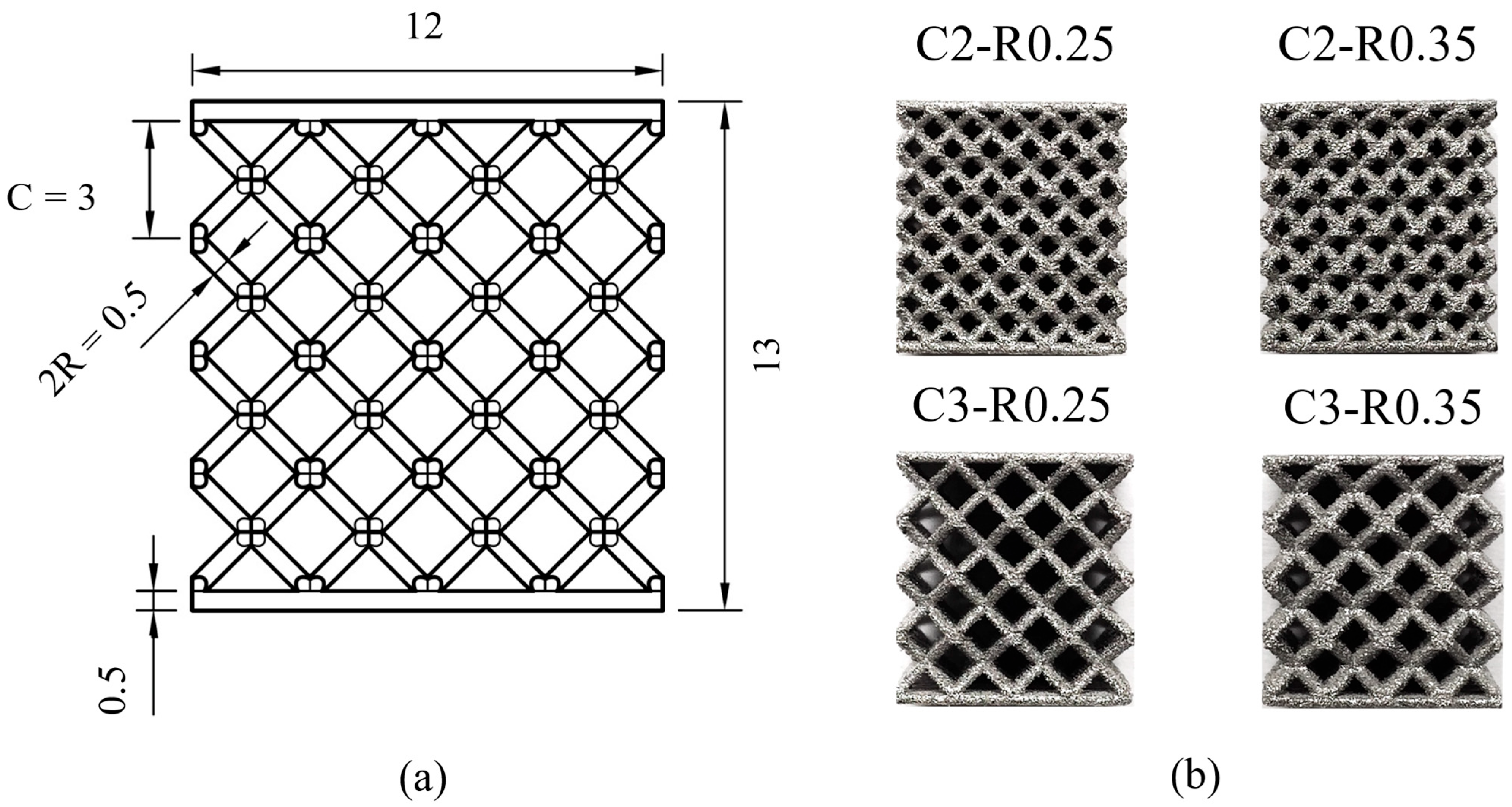
2.1. LPBF of MLSPs for Compression Tests
- C = 2 mm or 3 mm;
- R = 0.25 mm or 0.35 mm.
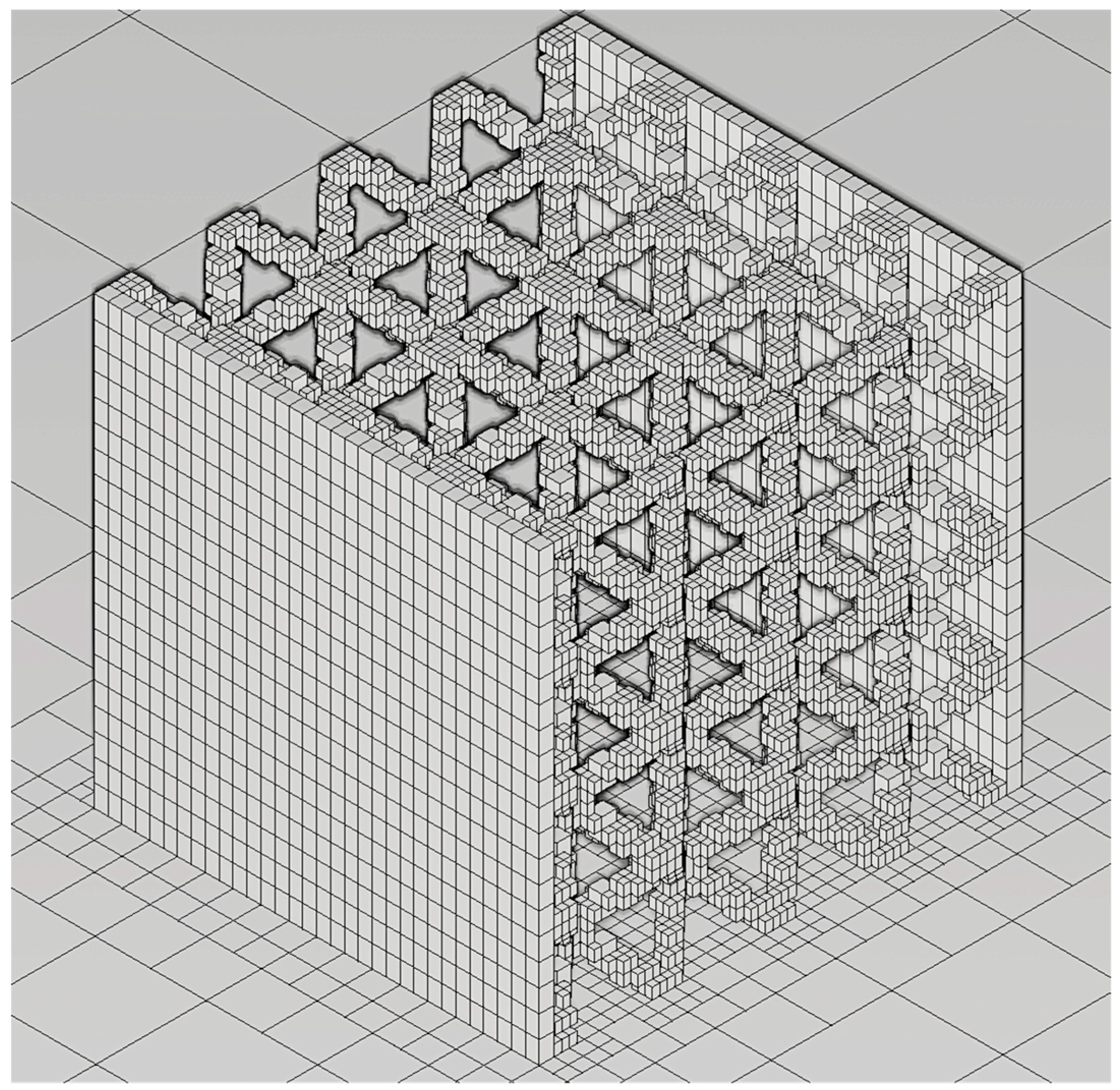
2.2. Numerical Simulations
3. Results and Discussion
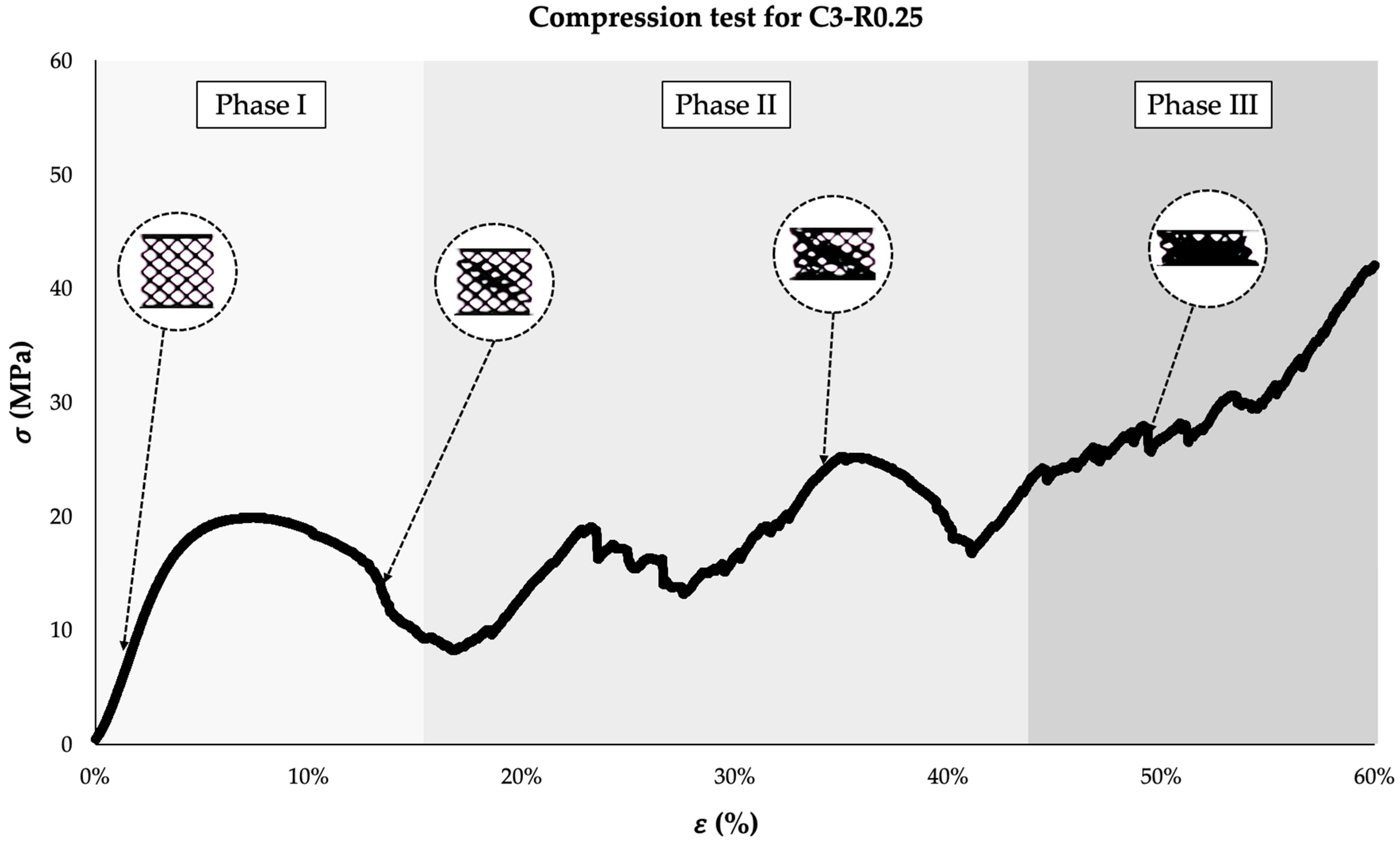
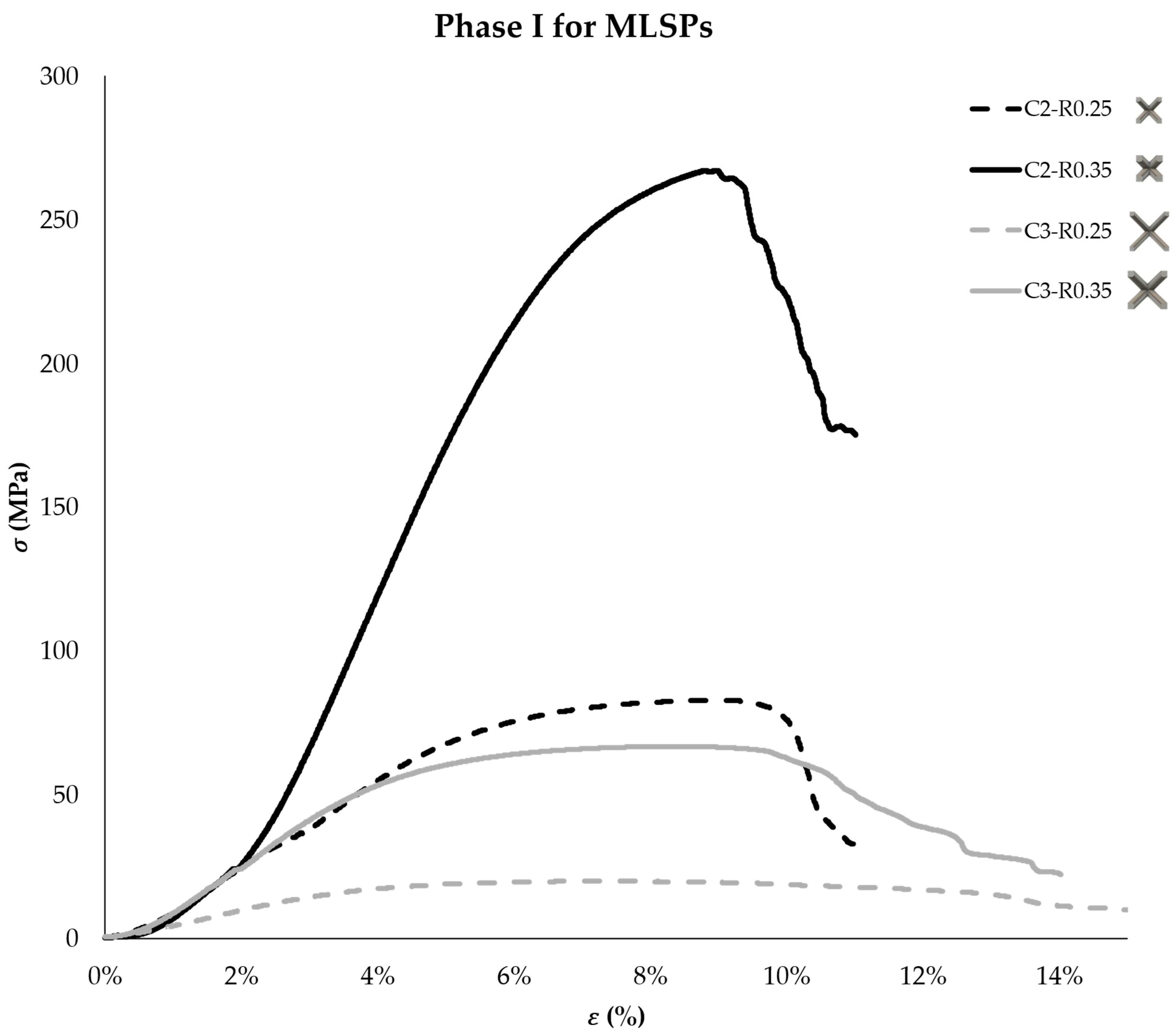
3.1. Mechanical Behavior of MLSPs Under Compressive Load
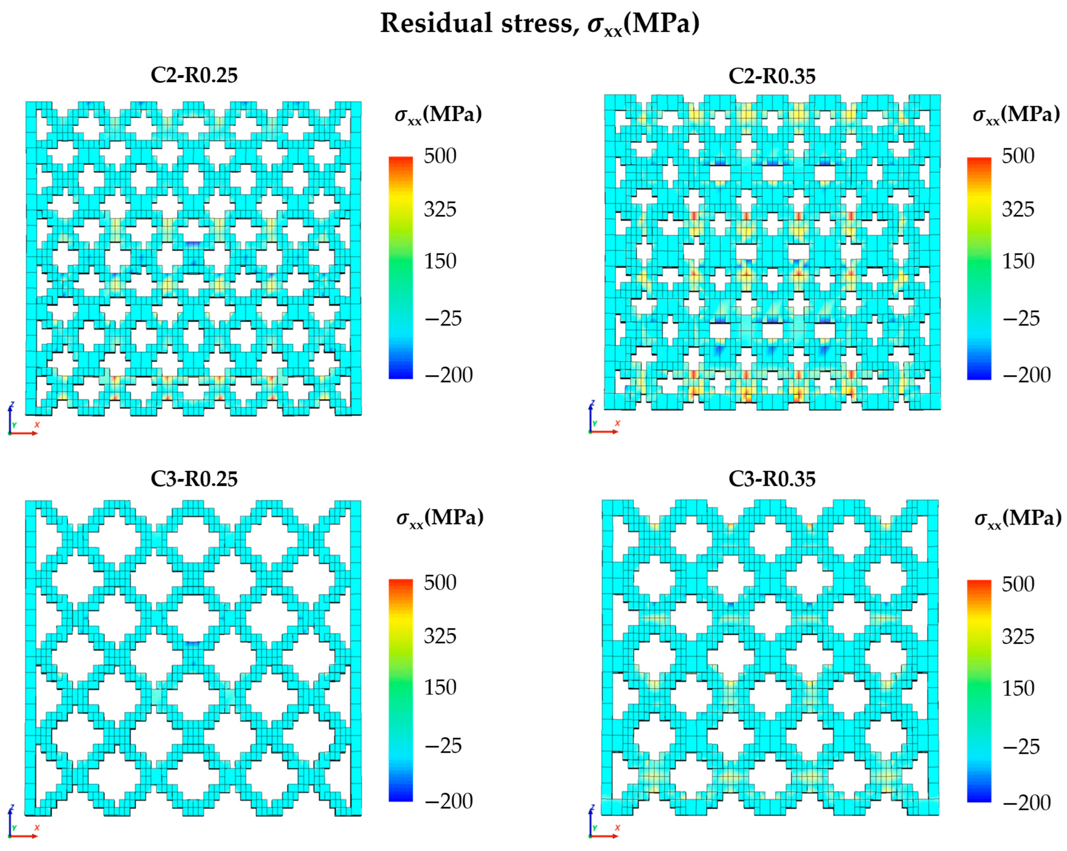
3.2. Numerical Simulation and Residual Stress Prediction for MLSPs
4. Conclusions
- MLSPs, when subjected to compressive load, show three different phases in their stress–strain curve: the initial elasto-plastic deformation of the lattice, followed by the alternation of peaks and valleys due to the alternation of densification and strut failure, and final densification, where the stress continuously increases.
- The cell size and beam radius strongly affect the mechanical behavior of MLSPs. This is due to their direct influence on the sample volume fraction. Specifically, when a high beam radius and small cell size are used, as for the C2-R0.35 samples, high compressive strength will be obtained.
- A mathematical formulation has been introduced to evaluate the volume variation depending on the geometrical parameters of the unit cell.
- The cell configuration also influences the residual stresses generated during the LPBF process. The C3-R0.25 cell configuration had the lowest volume fraction, which facilitated thermal exchange, resulting in a more uniform residual stress profile.
- In conclusion, a geometrical formulation has been provided to evaluate the effect of the beam radius and cell size on the volume fraction, which is one of the most influential factors in the compressive strength of TI-6Al-4V MLSPs. Moreover, an efficient numerical model has been proposed to predict the residual stresses in this kind of structure. These tools can be used by engineers in the design phase of MLSPs, saving them time and costs incurred due to the usual experimental campaign.
5. Research Limitations and Future Developments
Author Contributions
Funding
Data Availability Statement
Conflicts of Interest
Abbreviations
| AM | Additive manufacturing |
| BCC | Body-centered cubic |
| CFRC | Carbon fiber-reinforced composite |
| LPBF | Laser powder bed fusion |
| MLSPs | Metal lattice sandwich panels |
| TPMS | Triply periodic minimal surface |
References
- Gülcan, O.; Simsek, U.; Cokgunlu, O.; Özdemir, M.; Şendur, P.; Yapici, G.G. Effect of Build Parameters on the Compressive Behavior of Additive Manufactured CoCrMo Lattice Parts Based on Experimental Design. Metals 2022, 12, 1104. [Google Scholar] [CrossRef]
- Rahmani, R.; Bashiri, B.; Lopes, S.I.; Hussain, A.; Maurya, H.S.; Vilu, R. Sustainable Additive Manufacturing: An Overview on Life Cycle Impacts and Cost Efficiency of Laser Powder Bed Fusion. J. Manuf. Mater. Process. 2025, 9, 18. [Google Scholar] [CrossRef]
- De Leon, E.; Riensche, A.; Bevans, B.D.; Billings, C.; Siddique, Z.; Liu, Y. A Review of Modeling, Simulation, and Process Qualification of Additively Manufactured Metal Components via the Laser Powder Bed Fusion Method. J. Manuf. Mater. Process. 2025, 9, 22. [Google Scholar] [CrossRef]
- Tian, Y.; He, J.; Ren, H.; Zha, X.; Lin, K.; Zhou, M.; Xiong, Y. Effect of Process and Geometric Parameters on Residual Distortion of Ti-6Al-4V Body-Centered Cubic Lattice Structures in Laser Powder Bed Fusion. Addit. Manuf. Front. 2024, 3, 200170. [Google Scholar] [CrossRef]
- Blakey-Milner, B.; Gradl, P.; Snedden, G.; Brooks, M.; Pitot, J.; Lopez, E.; Leary, M.; Berto, F.; du Plessis, A. Metal Additive Manufacturing in Aerospace: A Review. Mater. Des. 2021, 209, 110008. [Google Scholar] [CrossRef]
- Imbalzano, G.; Tran, P.; Ngo, T.D.; Lee, P.V. Three-Dimensional Modelling of Auxetic Sandwich Panels for Localised Impact Resistance. J. Sandw. Struct. Mater. 2017, 19, 291–316. [Google Scholar] [CrossRef]
- Dong, L. Mechanical Responses of Ti-6Al-4V Cuboctahedral Truss Lattice Structures. Compos. Struct. 2020, 235, 111815. [Google Scholar] [CrossRef]
- Li, P.; Yang, F.; Liu, Y.; Bian, Y.; Zhang, S.; Wang, L.; Fan, H. Design of Dual-Phase Lattice Materials with Balanced Modulus, Strength and Energy Absorption Properties Based on Sudoku Arranged Reinforcement Phase Distribution. Comput. Struct. 2023, 286, 107093. [Google Scholar] [CrossRef]
- Chen, L.-Y.; Liang, S.-X.; Liu, Y.; Zhang, L.-C. Additive Manufacturing of Metallic Lattice Structures: Unconstrained Design, Accurate Fabrication, Fascinated Performances, and Challenges. Mater. Sci. Eng. R Rep. 2021, 146, 100648. [Google Scholar] [CrossRef]
- Zhumabekova, A.; Toleubekova, M.; Pham, T.T.; Talamona, D.; Perveen, A. Effect of Lattice Structure on Mechanical Properties of Ti-6Al-4V-Ta Alloy for Improved Antibacterial Properties. J. Manuf. Mater. Process. 2024, 8, 133. [Google Scholar] [CrossRef]
- Şimşek, U.; Gülcan, O.; Günaydın, K.; Tamer, A. Prediction of Compressive Behavior of Laser-Powder-Bed Fusion-Processed TPMS Lattices by Regression Analysis. J. Manuf. Mater. Process. 2024, 8, 16. [Google Scholar] [CrossRef]
- Rashid, R.; Masood, S.; Ruan, D.; Palanisamy, S.; Huang, X.; Rahman Rashid, R.A. Design Optimization and Finite Element Model Validation of LPBF-Printed Lattice-Structured Beams. Metals 2023, 13, 184. [Google Scholar] [CrossRef]
- Adelmann, B.; Hellmann, R. Mechanical Properties of LPBF-Built Titanium Lattice Structures—A Comparative Study of As-Built and Hot Isostatic Pressed Structures for Medical Implants. Metals 2022, 12, 2072. [Google Scholar] [CrossRef]
- Benedetti, M.; du Plessis, A.; Ritchie, R.O.; Dallago, M.; Razavi, S.M.J.; Berto, F. Architected Cellular Materials: A Review on Their Mechanical Properties Towards Fatigue-Tolerant Design and Fabrication. Mater. Sci. Eng. R Rep. 2021, 144, 100606. [Google Scholar] [CrossRef]
- Almonti, D.; Salvi, D.; Ucciardello, N. Optimization of Printing Parameters for Polyethylene Terephthalate Glycol Thin Honeycomb Structures with Shape-Memory Behaviors. Int. J. Adv. Manuf. Technol. 2025, 136, 4455–4469. [Google Scholar] [CrossRef]
- Dwivedi, K.; Joshi, S.; Nair, R.; Sapre, M.S.; Jatti, V. Optimizing 3D Printed Diamond Lattice Structure and Investigating the Influence of Process Parameters on Their Mechanical Integrity Using Nature-Inspired Machine Learning Algorithms. Mater. Today Commun. 2024, 38, 108233. [Google Scholar] [CrossRef]
- Wei, K.; Yang, Q.; Yang, X.; Tao, Y.; Xie, H.; Qu, Z.; Fang, D. Mechanical Analysis and Modeling of Metallic Lattice Sandwich Additively Fabricated by Selective Laser Melting. Thin-Walled Struct. 2020, 146, 106189. [Google Scholar] [CrossRef]
- Georges, H.; Großmann, A.; Mittelstedt, C.; Becker, W. Structural Modeling of Sandwich Panels with Additively Manufactured Strut-Based Lattice Cores. Addit. Manuf. 2022, 55, 102788. [Google Scholar] [CrossRef]
- Wei, Y.; Zhang, C.; Yuan, Y.; Chen, P.; Huang, C.; Li, J.; Yuan, M. Blast Response of Additive Manufactured Ti–6Al–4V Sandwich Panels. Int. J. Impact. Eng. 2023, 176, 104553. [Google Scholar] [CrossRef]
- Gibson, I.; Rosen, D.; Stucker, B. Additive Manufacturing Technologies: 3D Printing, Rapid Prototyping, and Direct Digital Manufacturing, 2nd ed; Springer: New York, NY, USA, 2015; ISBN 9781493921133. [Google Scholar]
- Pupillo, D.; Di Franco, F.; Palmeri, D.; Pollara, G.; Buffa, G.; Fratini, L.; Santamaria, M. Surface Treatments on 3D Printed Ti6Al4V Biomedical Plates to Enhance Corrosion Resistance in Simulated Physiological Solutions and Under Inflammatory Conditions. Corros. Sci. 2024, 240, 112451. [Google Scholar] [CrossRef]
- Bici, M.; Brischetto, S.; Campana, F.; Ferro, C.G.; Seclì, C.; Varetti, S.; Maggiore, P.; Mazza, A. Development of a Multifunctional Panel for Aerospace Use Through SLM Additive Manufacturing. Procedia CIRP 2018, 67, 215–220. [Google Scholar] [CrossRef]
- Ferro, C.G.; Varetti, S.; Maggiore, P.; Lombardi, M.; Biamino, S.; Manfredi, D.; Calignano, F. Design and Characterization of Trabecular Structures for an Anti-Icing Sandwich Panel Produced by Additive Manufacturing. J. Sandw. Struct. Mater. 2020, 22, 1111–1131. [Google Scholar] [CrossRef]
- Guo, H.; Wang, H.; Li, X.; Dong, Z.; Zhang, L.; Li, W. Investigation of Mechanical Properties of Laser Powder Bed Fused AlSi10Mg Lattice Structures Using GTN Damage Model. J. Mater. Res. Technol. 2024, 29, 1937–1948. [Google Scholar] [CrossRef]
- Mines, R.A.W.; Tsopanos, S.; Shen, Y.; Hasan, R.; McKown, S.T. Drop Weight Impact Behaviour of Sandwich Panels with Metallic Micro Lattice Cores. Int. J. Impact Eng. 2013, 60, 120–132. [Google Scholar] [CrossRef]
- Hou, S.; Li, T.; Jia, Z.; Wang, L. Mechanical Properties of Sandwich Composites with 3d-Printed Auxetic and Non-Auxetic Lattice Cores Under Low Velocity Impact. Mater. Des. 2018, 160, 1305–1321. [Google Scholar] [CrossRef]
- Acanfora, V.; Zarrelli, M.; Riccio, A. Experimental and Numerical Assessment of the Impact Behaviour of a Composite Sandwich Panel with a Polymeric Honeycomb Core. Int. J. Impact Eng. 2023, 171, 104392. [Google Scholar] [CrossRef]
- Wu, Q.; Gao, Y.; Wei, X.; Mousanezhad, D.; Ma, L.; Vaziri, A.; Xiong, J. Mechanical Properties and Failure Mechanisms of Sandwich Panels with Ultra-Lightweight Three-Dimensional Hierarchical Lattice Cores. Int. J. Solids Struct. 2018, 132–133, 171–187. [Google Scholar] [CrossRef]
- Arputharaj, J.D.; Nafisi, S.; Ghomashchi, R. Compression Behaviour of L-PBF-Manufactured Ti6Al4V BCC Lattices. Metals 2025, 15, 220. [Google Scholar] [CrossRef]
- Güden, M.; Alpkaya, A.T.; Hamat, B.A.; Hızlı, B.; Taşdemirci, A.; Tanrıkulu, A.A.; Yavaş, H. The Quasi-Static Crush Response of Electron-Beam-Melt Ti6Al4V Body-Centred-Cubic Lattices: The Effect of the Number of Cells, Strut Diameter and Face Sheet. Strain 2022, 58, e12411. [Google Scholar] [CrossRef]
- Mazur, M.; Leary, M.; Sun, S.; Vcelka, M.; Shidid, D.; Brandt, M. Deformation and Failure Behaviour of Ti-6Al-4V Lattice Structures Manufactured by Selective Laser Melting (SLM). Int. J. Adv. Manuf. Technol. 2015, 84, 1391–1411. [Google Scholar] [CrossRef]
- Buffa, G.; Costa, A.; Palmeri, D.; Pollara, G.; Fratini, L. Defining a New Process Window for LPBF of Ti-6Al-4V Based on Micro-Warping Phenomena. CIRP J. Manuf. Sci. Technol. 2024, 52, 1–11. [Google Scholar] [CrossRef]
- Palmeri, D.; Pollara, G.; Licari, R.; Micari, F. Finite Element Method in L-PBF of Ti-6Al-4V: Influence of Laser Power and Scan Speed on Residual Stress and Part Distortion. Metals 2023, 13, 1907. [Google Scholar] [CrossRef]
- Peter, N.; Pitts, Z.; Thompson, S.; Saharan, A. Benchmarking Build Simulation Software for Laser Powder Bed Fusion of Metals. Addit. Manuf. 2020, 36, 101531. [Google Scholar] [CrossRef]
- Gouge, M.; Michaleris, P.; Denlinger, E.; Irwin, J. The Finite Element Method for the Thermo-Mechanical Modeling of Additive Manufacturing Processes. In Thermo-Mechanical Modeling of Additive Manufacturing; Elsevier: Amsterdam, The Netherlands, 2017; pp. 19–38. ISBN 9780128118207. [Google Scholar]
- Sih, S.S.; Barlow, J.W. The Prediction of the Emissivity and Thermal Conductivity of Powder Beds. Part. Sci. Technol. 2004, 22, 427–440. [Google Scholar] [CrossRef]
- Li, C.; Gouge, M.F.; Denlinger, E.R.; Irwin, J.E.; Michaleris, P. Estimation of Part-to-Powder Heat Losses as Surface Convection in Laser Powder Bed Fusion. Addit. Manuf. 2019, 26, 258–269. [Google Scholar] [CrossRef]
- Gouge, M.; Denlinger, E.; Irwin, J.; Li, C.; Michaleris, P. Experimental Validation of Thermo-Mechanical Part-Scale Modeling for Laser Powder Bed Fusion Processes. Addit. Manuf. 2019, 29, 100771. [Google Scholar] [CrossRef]
- Liu, X.; Wada, T.; Suzuki, A.; Takata, N.; Kobashi, M.; Kato, M. Understanding and Suppressing Shear Band Formation in Strut-Based Lattice Structures Manufactured by Laser Powder Bed Fusion. Mater. Des. 2021, 199, 109416. [Google Scholar] [CrossRef]
- Pattillo, P.D. Column Stability. In Elements of Oil and Gas Well Tubular Design; Elsevier: Amsterdam, The Netherlands, 2018; pp. 273–313. [Google Scholar]
- Kelly, C.N.; Kahra, C.; Maier, H.J.; Gall, K. Processing, Structure, and Properties of Additively Manufactured Titanium Scaffolds with Gyroid-Sheet Architecture. Addit. Manuf. 2021, 41, 101916. [Google Scholar] [CrossRef]
- Leuders, S.; Thöne, M.; Riemer, A.; Niendorf, T.; Tröster, T.; Richard, H.A.; Maier, H.J. On the Mechanical Behaviour of Titanium Alloy TiAl6V4 Manufactured by Selective Laser Melting: Fatigue Resistance and Crack Growth Performance. Int. J. Fatigue 2013, 48, 300–307. [Google Scholar] [CrossRef]


| Sample ID | C (mm) | R (mm) | Vf | Unit Cell | 3D Sketch of the Sample |
|---|---|---|---|---|---|
| C2-R0.25 | 2 | 0.25 | 0.264 |  | 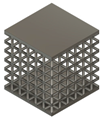 |
| C2-R0.35 | 2 | 0.35 | 0.457 |  | 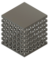 |
| C3-R0.25 | 3 | 0.25 | 0.128 |  | 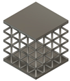 |
| C3-R0.35 | 3 | 0.35 | 0.234 |  |  |
| T [°C] | Cp (J/kg) | k (W/m/°C) |
|---|---|---|
| 0 | 565 | 6.6 |
| 20 | 565 | 6.6 |
| 93 | 565 | 7.3 |
| 205 | 574 | 9.1 |
| 315 | 603 | 10.6 |
| 425 | 649 | 12.6 |
| 540 | 699 | 14.6 |
| 650 | 770 | 17.5 |
| 760 | 858 | 17.5 |
| 870 | 959 | 17.5 |
| T [°C] | σy (MPa) | E (GPa) | α (µm/m°C) |
|---|---|---|---|
| 0 | 777.15 | 105.00 | 8.60 |
| 20 | 768.15 | 103.95 | 8.64 |
| 250 | 664.65 | 91.81 | 9.20 |
| 500 | 552.15 | 78.63 | 9.70 |
| 800 | 417.15 | 62.80 | 9.70 |
| Boundary Conditions | Description |
|---|---|
| Mechanical | fixed build plate, no translation or distortion of the substrate is allowed |
| Thermal | Tsubstrate = 200 °C |
| Tchamber = 25 °C | |
| heat loss to the powder is simulated by assigning a convection coefficient value (h = 25 W/m2/°C) to the part surfaces |
| ID | Total Sample Volume () [mm3] | Skins’ Volume () [mm3] | Sample Volume () [mm3] | Lattice Region Volume () [mm3] | Unit Cell Volume () [mm3] | Number of Unit Cells () | Volume Fraction () |
|---|---|---|---|---|---|---|---|
| C2-R0.25 | 1872 | 144 | 599.398 | 455.398 | 2.108 | 216 | 0.264 |
| C2-R0.35 | 1872 | 144 | 932.879 | 788.879 | 3.652 | 216 | 0.457 |
| C3-R0.25 | 1872 | 144 | 365.995 | 221.995 | 3.469 | 64 | 0.128 |
| C3-R0.35 | 1872 | 144 | 548.384 | 404.384 | 6.319 | 64 | 0.234 |
| ID | After the Printing Process | After the Samples’ Removal | ||
|---|---|---|---|---|
| Maximum [MPa] | Maximum [MPa] | Maximum [MPa] | Minimum [MPa] | |
| C2-R0.25 | 725 | −498 | 593 | −470 |
| C2-R0.35 | 917 | −559 | 737 | −615 |
| C3-R0.25 | 542 | −328 | 338 | −292 |
| C3-R0.35 | 660 | −446 | 722 | −586 |
Disclaimer/Publisher’s Note: The statements, opinions and data contained in all publications are solely those of the individual author(s) and contributor(s) and not of MDPI and/or the editor(s). MDPI and/or the editor(s) disclaim responsibility for any injury to people or property resulting from any ideas, methods, instructions or products referred to in the content. |
© 2025 by the authors. Licensee MDPI, Basel, Switzerland. This article is an open access article distributed under the terms and conditions of the Creative Commons Attribution (CC BY) license (https://creativecommons.org/licenses/by/4.0/).
Share and Cite
Pollara, G.; Palmeri, D.; Licari, R.; Barcellona, A. On the Effect of the Cell Size and Beam Radius on the Compressive Strength and Residual Stresses of Ti-6Al-4V BCC Lattice Sandwich Structures Manufactured by L-PBF. J. Manuf. Mater. Process. 2025, 9, 192. https://doi.org/10.3390/jmmp9060192
Pollara G, Palmeri D, Licari R, Barcellona A. On the Effect of the Cell Size and Beam Radius on the Compressive Strength and Residual Stresses of Ti-6Al-4V BCC Lattice Sandwich Structures Manufactured by L-PBF. Journal of Manufacturing and Materials Processing. 2025; 9(6):192. https://doi.org/10.3390/jmmp9060192
Chicago/Turabian StylePollara, Gaetano, Dina Palmeri, Roberto Licari, and Antonio Barcellona. 2025. "On the Effect of the Cell Size and Beam Radius on the Compressive Strength and Residual Stresses of Ti-6Al-4V BCC Lattice Sandwich Structures Manufactured by L-PBF" Journal of Manufacturing and Materials Processing 9, no. 6: 192. https://doi.org/10.3390/jmmp9060192
APA StylePollara, G., Palmeri, D., Licari, R., & Barcellona, A. (2025). On the Effect of the Cell Size and Beam Radius on the Compressive Strength and Residual Stresses of Ti-6Al-4V BCC Lattice Sandwich Structures Manufactured by L-PBF. Journal of Manufacturing and Materials Processing, 9(6), 192. https://doi.org/10.3390/jmmp9060192