
Prediction of Milling Deformation for Frame-Type Thin-Walled Parts Considering Workblank Initial Residual Stress and Milling Force

 , and
, and
Abstract
1. Introduction
2. Measurement of Workblank Initial Residual Stress and Milling Force
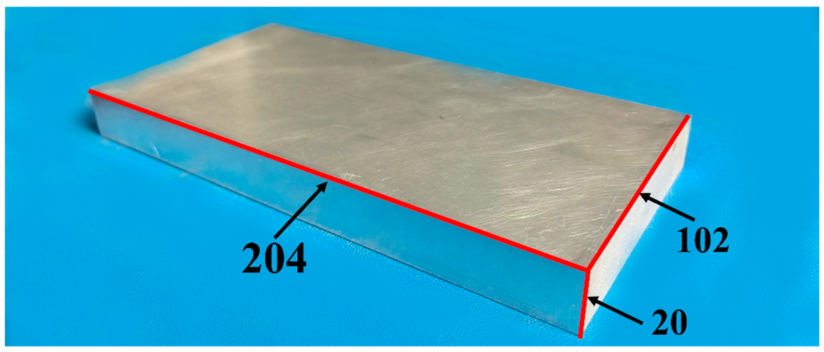
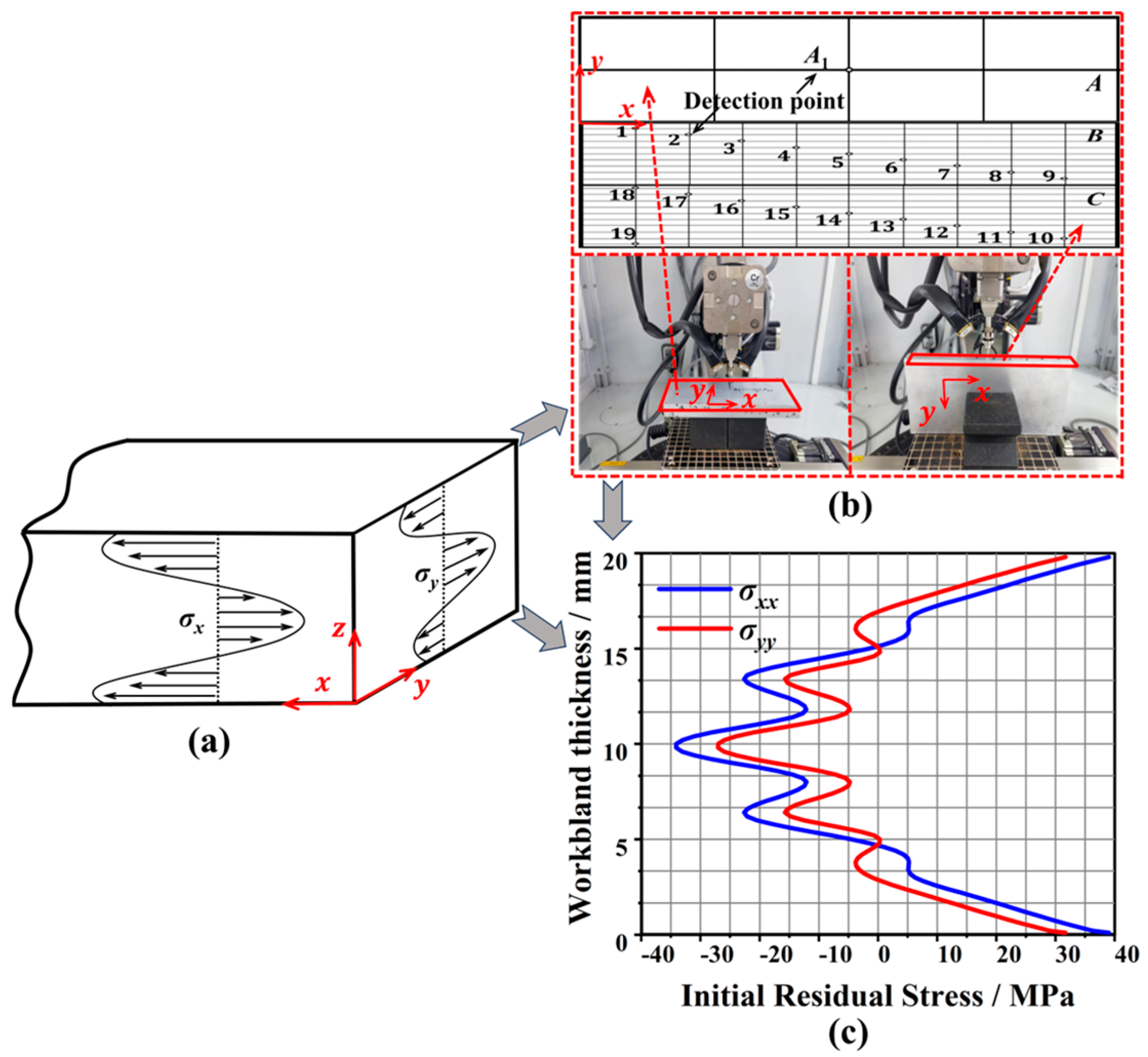
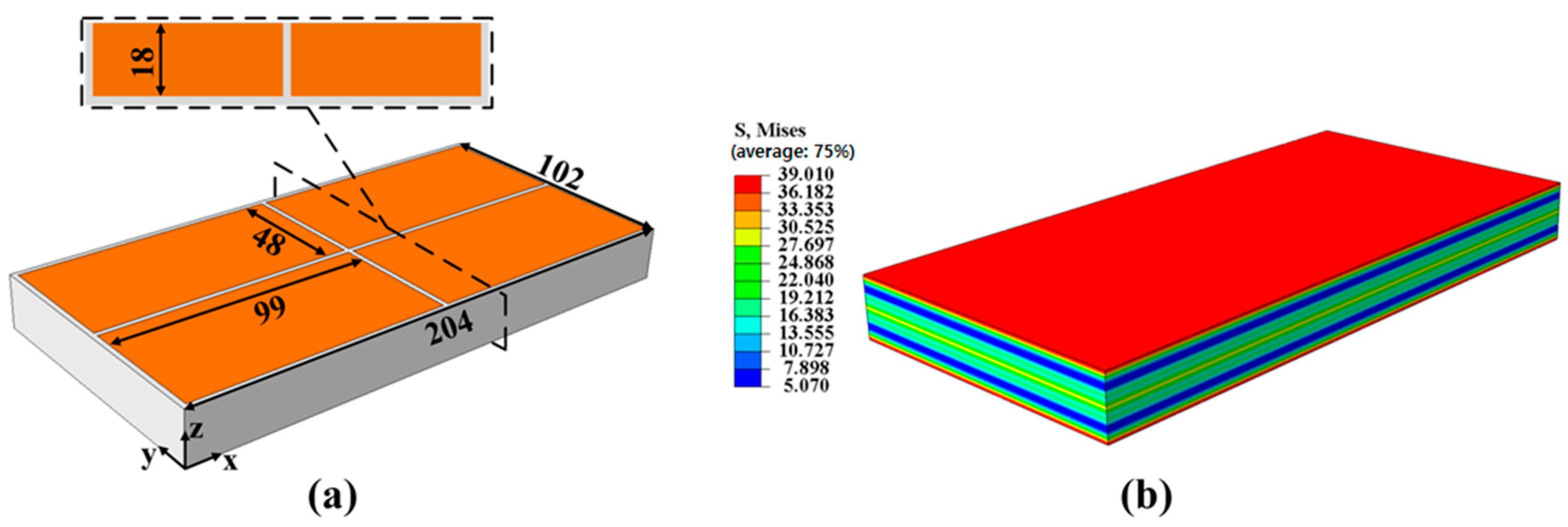
2.1. Determination of the Workblank Initial Residual Stress Field
- (1)
- Self-balance. In the absence of external forces, the vector sums of stress and torque in all directions inside the workblank are zero, and the internal residual stress field is in static equilibrium.
- (2)
- Uniform distribution in the same layer. The residual stresses along the length and width direction within the same thickness layer of the material can be regarded as equal.
- (3)
- Symmetrical distribution. The residual stress of the material in the thickness direction can be considered to be equal to zero, and the residual stress in the length and width directions is distributed symmetrically about the midplane of the blank.
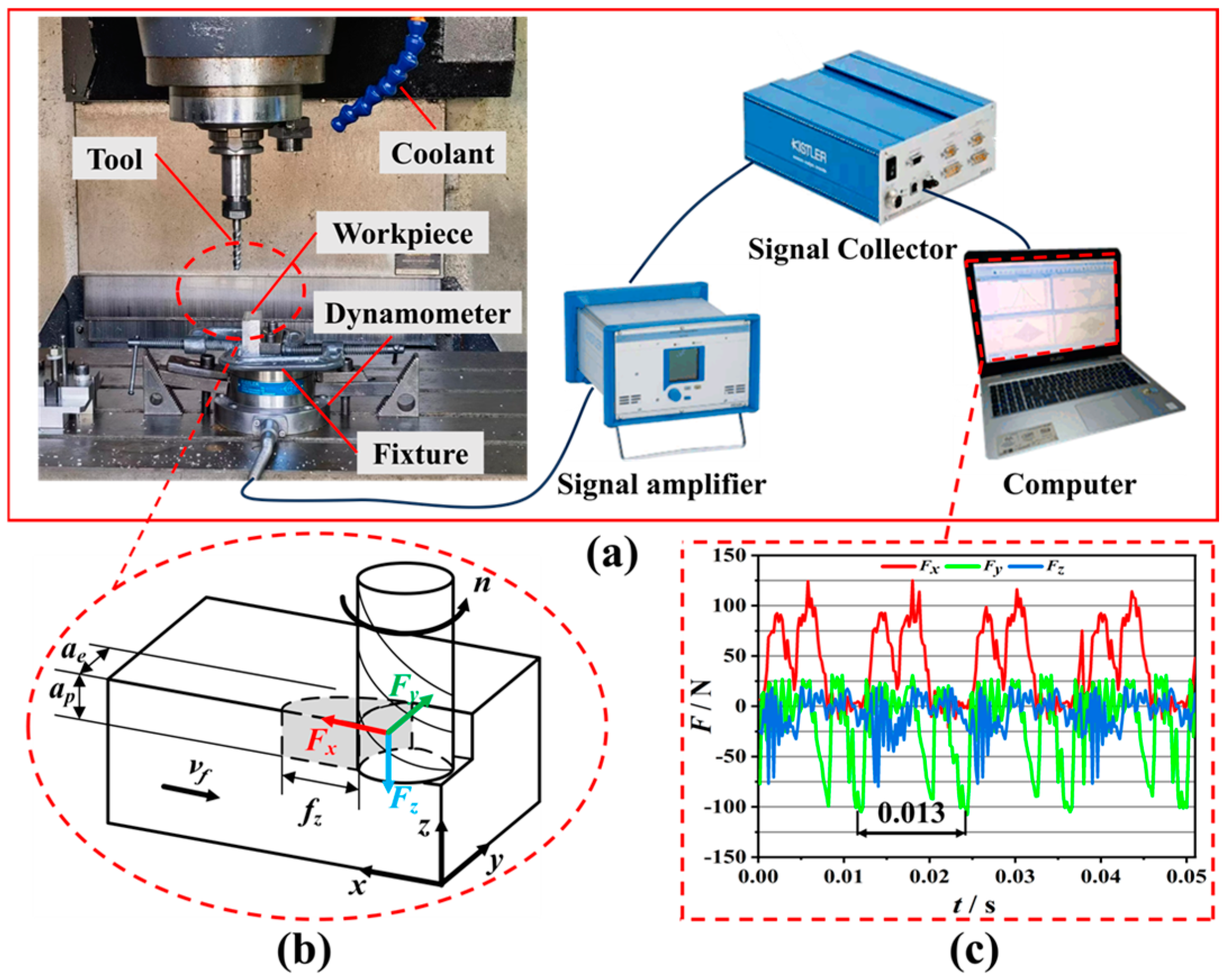
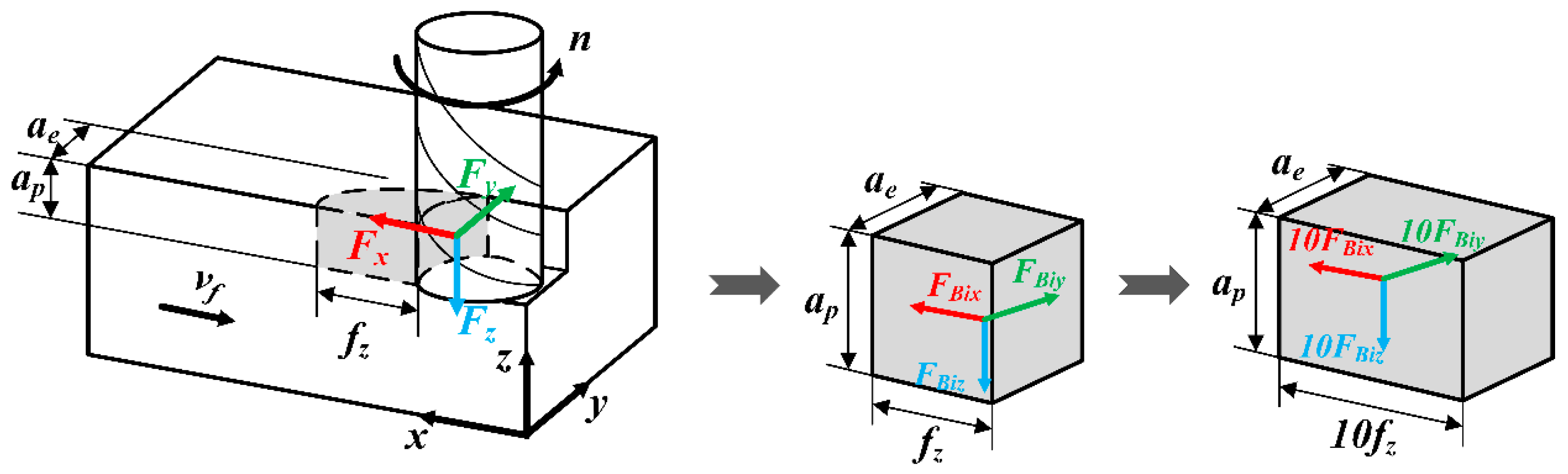
2.2. Experiments for Milling Forces
3. Establishment of the Deformation Prediction Method for Frame-Type Thin-Walled Parts
3.1. Establishment of the Workblank Model and Loading of the Initial Stress Field
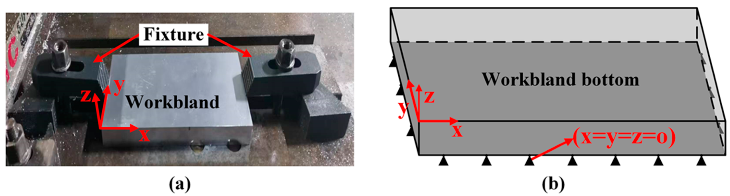
3.2. Setting of Boundary Conditions for the Workblank Model
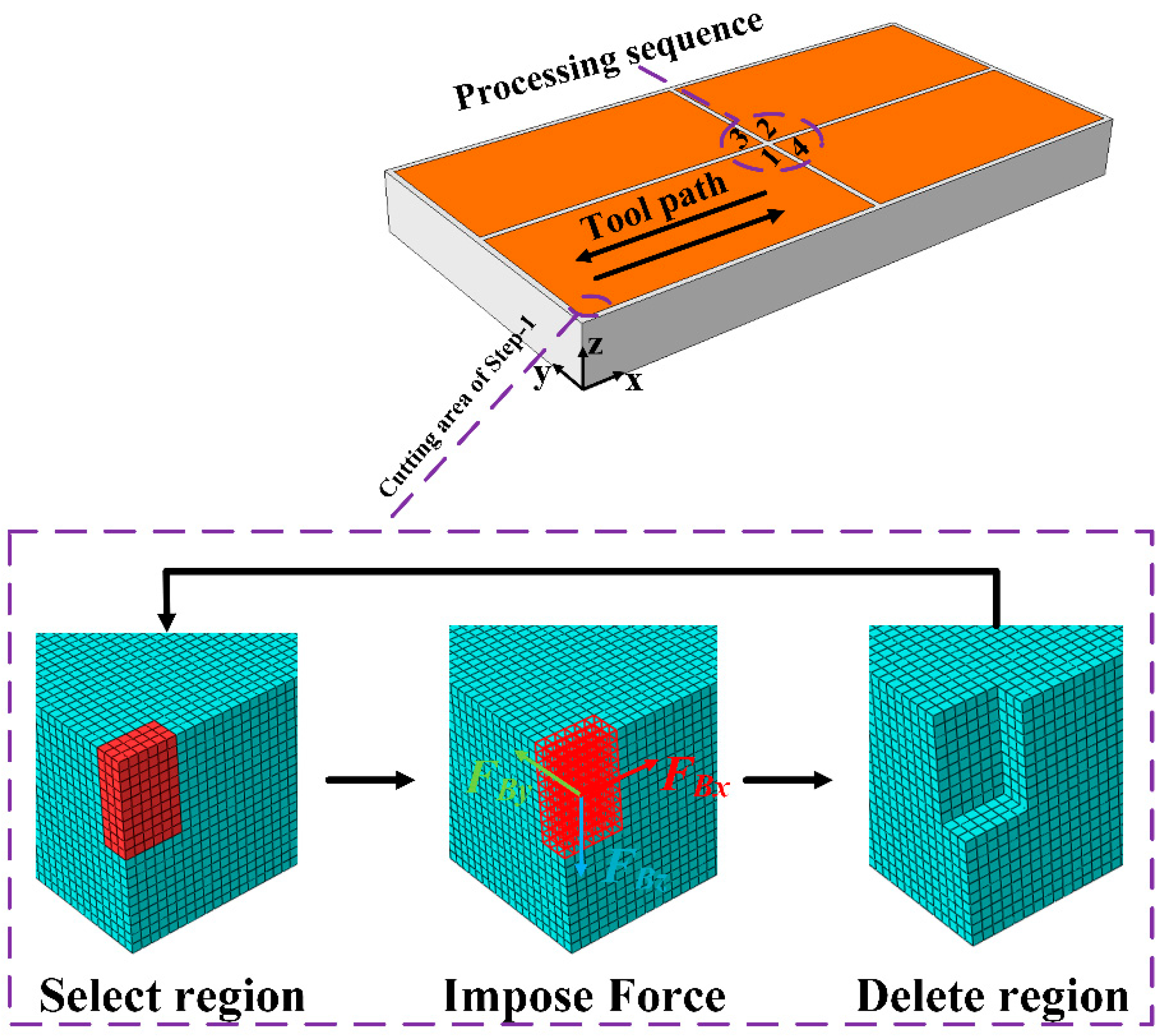
3.3. Division of the Milling Removal Region and Application of Milling Force
3.4. Finite Element Simulation of Milling Deformation for Frame-Type Thin-Walled Parts
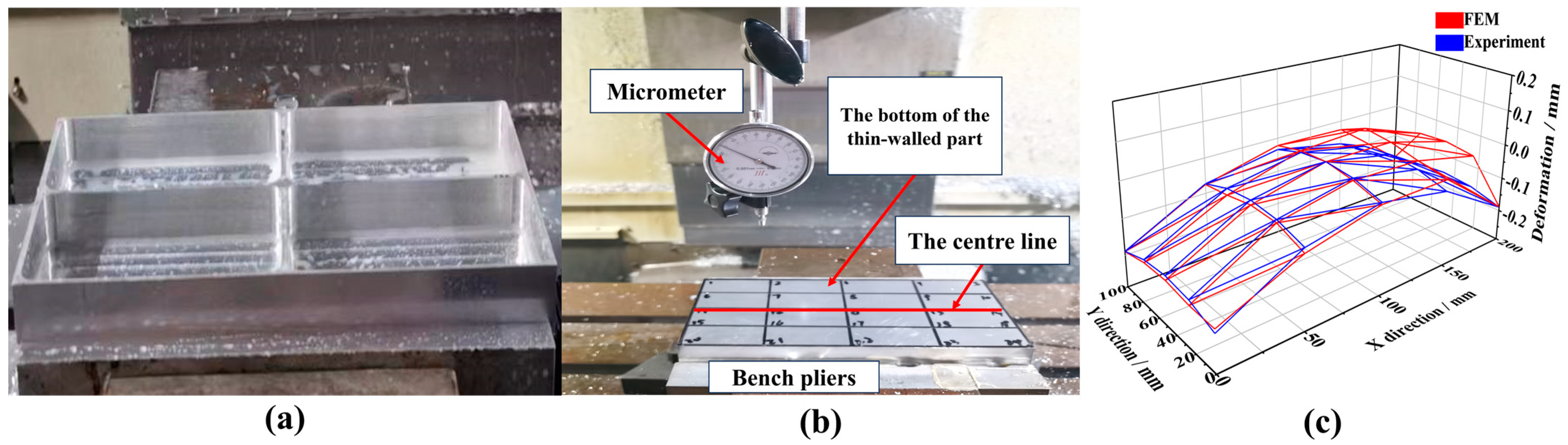
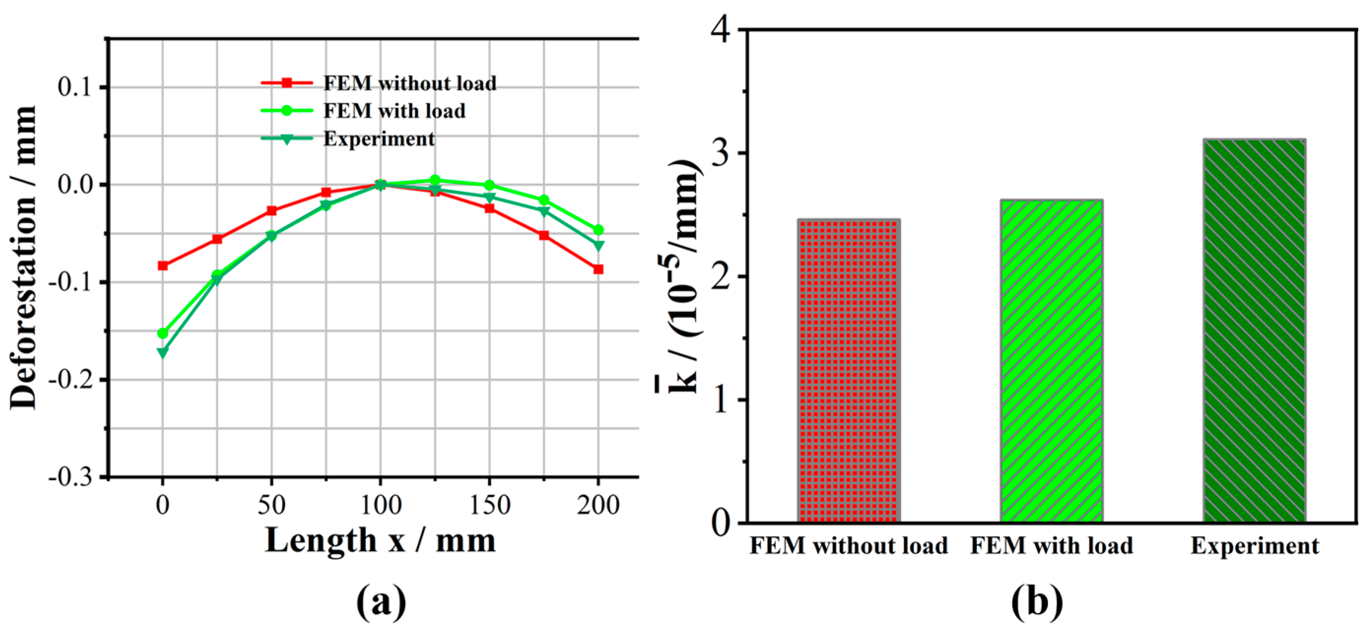
3.5. Experimental Verification of the Simulation Method
4. Influence of Process Strategy on Milling Deformation of Frame-Type Parts
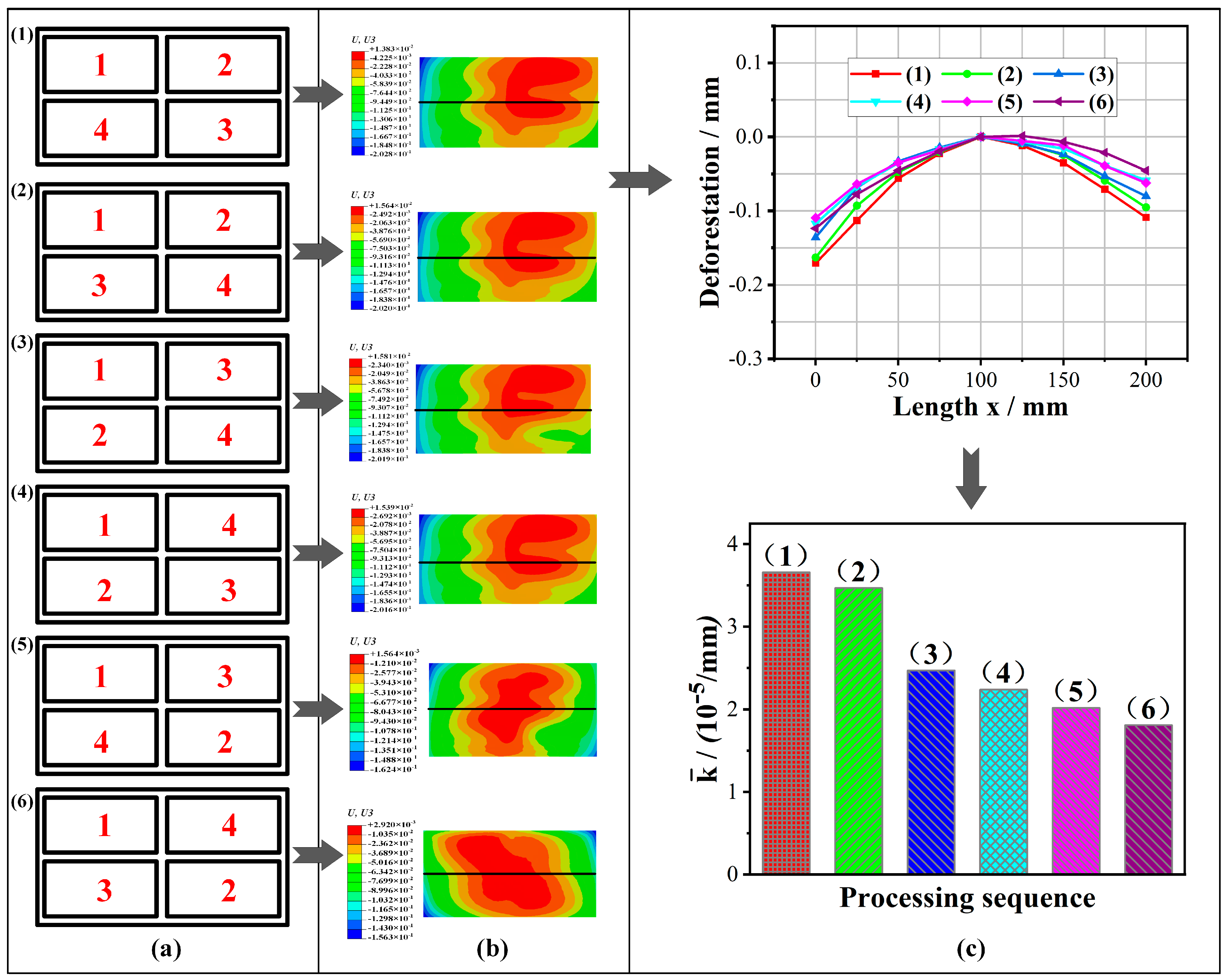
4.1. Influence of FPS on the Milling Deformation
4.2. Influence of Tool Path on Milling Deformation
4.3. Influence of SFORD on the Machining Deformations
5. Conclusions
- (1)
- A reliable prediction result can be obtained by this method, and the prediction results of the deformation characteristics for the frame-type parts are in good agreement with the experiment results.
- (2)
- When milling frame parts, smaller machining deformation can be obtained by using the FPS of prioritizing the width direction and symmetrical milling.
- (3)
- The deformation of the framed part is the smallest in the inner loop under four different machining paths: single way, reciprocating type, inner loop, and outer loop.
- (4)
- The milling deformation of the framed parts decreases and then increases with the increase of the removal depth, where the deformation is the smallest when the SFORD is 3 mm.
Author Contributions
Funding
Data Availability Statement
Conflicts of Interest
Abbreviations
| FPS | Frame processing sequence |
| SFORD | Single frame one-time removal depth |
| FEM | Finite element method |
| EDM | Element deletion method |
References
- Yue, C.; Zhang, J.; Liu, X.; Chen, Z.; Liang, S.; Wang, L. Research progress on machining deformation of thin-walled parts in milling process. Acta Aeronaut. Astronaut. Sin. 2022, 43, 525164. [Google Scholar]
- Del Sol, I.; Rivero, A.; López de Lacalle, L.N.; Gamez, A.J. Thin-wall machining of light alloys: A review of models and industrial approaches. Materials 2019, 12, 12. [Google Scholar] [CrossRef] [PubMed]
- Aurrekoetxea, M.; Llanos, I.; Zelaieta, O.; López de Lacalle, L.N. Towards advanced prediction and control of machining distortion: A comprehensive review. Int. J. Adv. Manuf. Technol. 2022, 122, 2823–2848. [Google Scholar] [CrossRef]
- Santos, M.C.; Machado, A.R.; Sales, W.F.; Barrozo, M.A.; Ezugwu, E.O. Machining of aluminum alloys: A review. Int. J. Adv. Manuf. Technol. 2016, 86, 3067–3080. [Google Scholar] [CrossRef]
- Yiyang, Z.; Jian, M.; Gang, L.; Man, Z. A review on error generation and control in efficient precision machining of thin-walled parts. Int. J. Adv. Manuf. Technol. 2024, 133, 2083–2101. [Google Scholar] [CrossRef]
- Wang, X.; Zhao, B.; Ding, W.; Pu, C.; Wang, X.; Peng, S.; Ma, F. A short review on machining deformation control of aero-engine thin-walled casings. Int. J. Adv. Manuf. Technol. 2022, 121, 2971–2985. [Google Scholar] [CrossRef]
- Aurrekoetxea, M.; López de Lacalle, L.N.; Zelaieta, O.; Llanos, I. In-Process Machining Distortion Prediction Method Based on Bulk Residual Stresses Estimation from Reduced Layer Removal. J. Manuf. Mater. Process. 2024, 8, 9. [Google Scholar] [CrossRef]
- Wang, S.P.; Padmanaban, S. A new approach for FEM simulation of NC machining processes. AIP Conf. Proc. 2004, 712, 1371–1376. [Google Scholar]
- Chen, Z.; Yue, C.; Xu, Y.; Liu, X.; Liang, S.Y. An analytical machining deformation model of H-section multi-frame beam integral components. J. Mater. Process. Technol. 2023, 314, 117907. [Google Scholar] [CrossRef]
- Yang, Y.; Li, X.; Li, L.; He, N.; Zhao, G.; Chen, N.; Lan, H.; Zhou, Z. Investigation on deformation of single-sided stringer parts based on fluctuant initial residual stress. J. Mater. Process. Technol. 2019, 271, 623–633. [Google Scholar] [CrossRef]
- Wang, Z.; Sun, J.; Liu, L.; Wang, R.; Chen, W. An analytical model to predict the machining deformation of frame parts caused by residual stress. J. Mater. Process. Technol. 2019, 274, 116282. [Google Scholar] [CrossRef]
- Gao, H.; Zhang, Y.; Wu, Q.; Song, J. An analytical model for predicting the machining deformation of a plate blank considers biaxial initial residual stresses. Int. J. Adv. Manuf. Technol. 2017, 93, 1473–1486. [Google Scholar] [CrossRef]
- Gao, H.; Zhang, Y.; Wu, Q.; Li, B. Investigation on influences of initial residual stress on thin-walled part machining deformation based on a semi-analytical model. J. Mater. Process. Technol. 2018, 262, 437–448. [Google Scholar] [CrossRef]
- Saleem, W.; Ijaz, H.; Zain-ul-Abdein, M.; Taimoor, A.A.; Wang, Y. Studying control strategies for dimensional precision in aerospace parts machining. Int. J. Adv. Manuf. Technol. 2017, 18, 39–47. [Google Scholar] [CrossRef]
- Ma, Y.; Zhang, J.; Yu, D.; Feng, P.; Xu, C. Modeling of machining distortion for thin-walled components based on the internal stress field evolution. Int. J. Adv. Manuf. Technol. 2019, 103, 3597–3612. [Google Scholar] [CrossRef]
- D’Alvise, L.; Chantzis, D.; Schoinochoritis, B.; Salonitis, K. Modelling of part distortion due to residual stresses relaxation: An aeronautical case study. Procedia Cirp 2015, 31, 447–452. [Google Scholar] [CrossRef]
- Huang, X.; Sun, J.; Li, J. Effect of initial residual stress and machining-induced residual stress on the deformation of aluminium alloy plate. Stroj. Vestn-J. Mech. E 2015, 61, 131–137. [Google Scholar] [CrossRef]
- Aurrekoetxea, M.; López de Lacalle, L.N.; Llanos, I. Machining stresses and initial geometry on bulk residual stresses characterization by on-machine layer removal. Materials 2020, 13, 1445. [Google Scholar] [CrossRef]
- Tang, Z.T.; Yu, T.; Xu, L.Q.; Liu, Z.Q. Machining deformation prediction for frame components considering multifactor coupling effects. Int. J. Adv. Manuf. Technol. 2013, 68, 187–196. [Google Scholar] [CrossRef]
- Madariaga, A.; Perez, I.; Arrazola, P.J.; Sanchez, R.; Ruiz, J.J.; Rubio, F.J. Reduction of distortions in large aluminium parts by controlling machining-induced residual stresses. Int. J. Adv. Manuf. Technol. 2018, 97, 967–978. [Google Scholar] [CrossRef]
- Zheng, J.Y.; Voyle, R.; Tang, H.P.; Mannion, A. Study of distortion on milled thin-wall aluminum parts influenced by initial residual stress and toolpath strategy. Int. J. Adv. Manuf. Technol. 2023, 127, 237–251. [Google Scholar] [CrossRef]
- Rajaa, S.M.; Abdulhadi, H.A.; Jabur, K.S.; Mohammed, G.R. Aging time effects on the mechanical properties of Al 6061-T6 alloy. Eng. Technol. Appl. Sci. 2018, 8, 3113–3115. [Google Scholar] [CrossRef]
- Yi, S.; Wu, Y.; Gong, H.; Peng, C.; He, Y. Experimental analysis and prediction model of milling-induced residual stress of aeronautical aluminum alloys. Appl. Sci. 2021, 11, 5881. [Google Scholar] [CrossRef]
- Weber, D.; Kirsch, B.; D ‘Elia, C.R.; Linke, B.S.; Hill, M.R.; Aurich, J.C. Simulation-Based Investigation of the Distortion of Milled Thin-Walled Aluminum Structural Parts Due to Residual Stresses. In Proceedings of the 3rd Conference on Physical Modeling for Virtual Manufacturing Systems and Processes; Springer International Publishing: Cham, Switzerland, 2023; pp. 149–169. [Google Scholar]
- Weber, D.; Kirsch, B.; Jonsson, J.E.; D’Elia, C.R.; Linke, B.S.; Hill, M.R.; Aurich, J.C. Simulation based compensation techniques to minimize distortion of thin-walled monolithic aluminum parts due to residual stresses. CIRP J. Manuf. Sci. Technol. 2022, 38, 427–441. [Google Scholar] [CrossRef]
- Bi, Y.B.; Cheng, Q.L.; Dong, H.Y.; Ke, Y.L. Machining distortion prediction of aerospace monolithic components. J. Zhejiang Univ.-Sci. A. 2009, 10, 661–668. [Google Scholar] [CrossRef]
- Liping, W.A.N.G.; Hao, S.I.; Liheng, G.U. Prediction of cutting forces in flank milling of parts with non-developable ruled surfaces. Chin. J. Aeronaut. 2019, 32, 1788–1796. [Google Scholar]
- Sanz-Calle, M.; Iglesias, A.; de Lacalle, L.L.; Dombovari, Z.; Munoa, J. Optimal milling cutter helix selection for period doubling chatter suppression. Int. J. Mach. Tool. Manu. 2024, 202, 104211. [Google Scholar] [CrossRef]


| Element | Si | Fe | Cu | Mn | Mg | Cr | Zn | Ti | Al |
|---|---|---|---|---|---|---|---|---|---|
| Content (%) | 0.5 | 0.43 | 0.21 | 0.05 | 1.06 | 0.12 | 0.07 | 0.04 | margin |
| Tensile Strength (MPa) | Yield Strength (MPa) | Density (kg/m3) | Elongation (%) | Modulus of Elasticity (GPa) | Durometer (HB) |
|---|---|---|---|---|---|
| 261 | 164 | 2700 | 14 | 69 | 95 |
| n (r/min) | vf (mm/min) | ap (mm) | ae (mm) |
|---|---|---|---|
| 4500 | 800 | 1 | 6 |
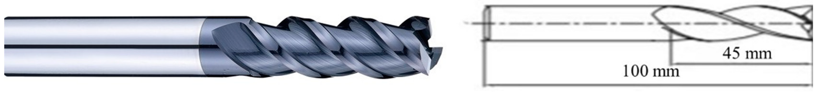
| Material | Number of Teeth | Diameter | Helix Angle |
|---|---|---|---|
| Cemented Carbide | 3 | 10 mm | 45° |
Disclaimer/Publisher’s Note: The statements, opinions and data contained in all publications are solely those of the individual author(s) and contributor(s) and not of MDPI and/or the editor(s). MDPI and/or the editor(s) disclaim responsibility for any injury to people or property resulting from any ideas, methods, instructions or products referred to in the content. |
© 2025 by the authors. Licensee MDPI, Basel, Switzerland. This article is an open access article distributed under the terms and conditions of the Creative Commons Attribution (CC BY) license (https://creativecommons.org/licenses/by/4.0/).
Share and Cite
Ma, L.; Ba, S.; Zhang, Y.; Liu, H.; Li, L.; Gao, F.; Zhang, F.; Ma, J. Prediction of Milling Deformation for Frame-Type Thin-Walled Parts Considering Workblank Initial Residual Stress and Milling Force. J. Manuf. Mater. Process. 2025, 9, 146. https://doi.org/10.3390/jmmp9050146
Ma L, Ba S, Zhang Y, Liu H, Li L, Gao F, Zhang F, Ma J. Prediction of Milling Deformation for Frame-Type Thin-Walled Parts Considering Workblank Initial Residual Stress and Milling Force. Journal of Manufacturing and Materials Processing. 2025; 9(5):146. https://doi.org/10.3390/jmmp9050146
Chicago/Turabian StyleMa, Lijie, Shijie Ba, Yu Zhang, Hongwen Liu, Leyang Li, Fei Gao, Faping Zhang, and Junjin Ma. 2025. "Prediction of Milling Deformation for Frame-Type Thin-Walled Parts Considering Workblank Initial Residual Stress and Milling Force" Journal of Manufacturing and Materials Processing 9, no. 5: 146. https://doi.org/10.3390/jmmp9050146
APA StyleMa, L., Ba, S., Zhang, Y., Liu, H., Li, L., Gao, F., Zhang, F., & Ma, J. (2025). Prediction of Milling Deformation for Frame-Type Thin-Walled Parts Considering Workblank Initial Residual Stress and Milling Force. Journal of Manufacturing and Materials Processing, 9(5), 146. https://doi.org/10.3390/jmmp9050146