Article

Permea-Design: An Innovative Tool for Generating Triply Periodic Minimal Surface Scaffolds with Tailored Permeability

by
Matthew Bedding-Tyrrell
1,2,
Bjornar Sandnes
3,
Perumal Nithiarasu
2 and
Feihu Zhao
1,2,*
1
Department of Biomedical Engineering, Faculty of Science and Engineering, Swansea University, Swansea SA1 8EN, UK
2
Zienkiewicz Institute for Modelling, Data and AI, Swansea University, Swansea SA1 8EN, UK
3
Complex Flow Lab, Department of Chemical Engineering, Faculty of Science and Engineering, Swansea University, Swansea SA1 8EN, UK
*
Author to whom correspondence should be addressed.
J. Manuf. Mater. Process. 2025, 9(3), 72; https://doi.org/10.3390/jmmp9030072
Submission received: 22 January 2025 / Revised: 18 February 2025 / Accepted: 18 February 2025 / Published: 23 February 2025

Abstract

:
The permeability of a porous material is the measure of the ability of fluids to pass through it. The ability to control permeability is valued by tissue engineers who manufacture tissue engineering scaffolds that house cells/tissue and facilitate tissue growth. Therefore, a scaffold design software in which permeability can be entered as a variable in determining the structure and strut topology would be a desirable tool for tissue engineering researchers. The ability to factor permeability directly into the design of scaffolds facilitates more effective bone tissue engineering by enabling optimal nutrient transport and waste removal at regeneration sites. Additionally, having the ability to control the mechanical environment by indicating a region of acceptable porosities for in vitro cell culturing is desirable. This desirability is a result of porosity being a major determining factor in permeability, where increasing porosity will generally mean a higher permeability. Thus, having an upper bound on porosity means that higher-permeability structures can be determined whilst maintaining high values of mechanical strength. In this software, a method is discussed for modifying the Kozeny–Carman equation by incorporating level-set equations for different triply periodic minimal surface (TPMS) structures. Topology analysis is computed on six different TPMS structures in the toolbox, and a relationship between a topological constant and permeability is derived through the Kozeny–Carman equation. This relationship allows for an input of permeability as a factor in the determination of pore size, porosity, and scaffold structure. This novel method allows for scaffold design based on a tailored permeability to assist successful tissue engineering.

1. Introduction

Three-dimensional (3D) porous scaffolds play an important role in tissue engineering because they house the tissue cells, facilitate the growth of those cells, and produce the ECM (extracellular matrix) that is needed for tissue morphogenesis, differentiation, and homeostasis [1,2]. Among different scaffold designs, TPMS (triply periodic minimal surface) structures are valuable to bone tissue engineers because they combine an ability to mimic biological bone tissue with high mechanical strength, which is required for bone regeneration [3]. TPMS structures exhibit lower stress concentrations, which decreases the probability of scaffold failure whilst undergoing bone regeneration [4]. Many of the TPMS structures also have a high surface area to volume ratio, which allows for the optimal delivery of nutrients and oxygen to artificial bone tissues and regeneration sites [5].
Permeability is a key factor in influencing the environment of cells. It is the measure of how well a scaffold can direct and conduct the fluid flow. Fluid flow is important for two main reasons: it induces mechanical stimulation on cells, and it enables the delivery of nutrients to the growing cells [6]. Therefore, a higher permeability can enhance nutrient transport throughout the scaffold. Cell migration and growth during cell culture process is also dependent on the ability of nutrients to permeate through the scaffold [7]. The ability to tailor the scaffold permeability is valuable because it enables the adjustment of nutrient transport and mechanical stimulation on cells, which facilitates optimal growth conditions. It has previously been shown that scaffold porous geometries can influence the scaffold permeability and internal mechanical/fluidic environment within a bioreactor [8]. It has also been shown that tortuosity, porosity, and constriction factor all affect permeability [9]. A higher porosity will generally mean a higher permeability and lower wall shear stress under constant flow rate in a perfusion bioreactor. TPMS structures are known to have a high permeability, which allows for high levels of nutrient transport and waste removal. One important component in the high permeability of TPMS scaffolds is their low constriction factor, which is due to their periodicity in three independent directions. Another component of their high permeability is their low tortuosity, which is due to their network of interconnected pores. Thus, lower values of tortuosity and the constriction factor led to higher permeabilities [9]. Additional research has indicated permeability can also be described by porosity, specific surface area, and a geometric shape factor [10]. Software capable of estimating permeability is already widely used. For example, Alvascience is a software suite that can predict the permeability of the blood–brain barrier to an ‘accuracy equal or greater than 0.8’ [11]. Convolutional neural networks have also been used to predict permeability, where the permeability of low-resolution porous media were predicted to an R2 value of 0.896, where R2 is the coefficient of determination [12]. However, to the authors’ knowledge, there is no currently available software that can generate a structure to a tailored permeability.
In this study, we aim to create a toolbox that can design scaffolds to a tailored permeability. To achieve this, it is hypothesized that the Kozeny–Carman equation, which was originally used for calculating the permeability of porous media, can be modified by incorporating the level-set constant from TPMS level-set equations [13]. To test this hypothesis, relationships that relate the level-set constant to porosity and specific surface area need to be derived and then integrated into the Kozeny–Carman equation.

2. Materials and Methods

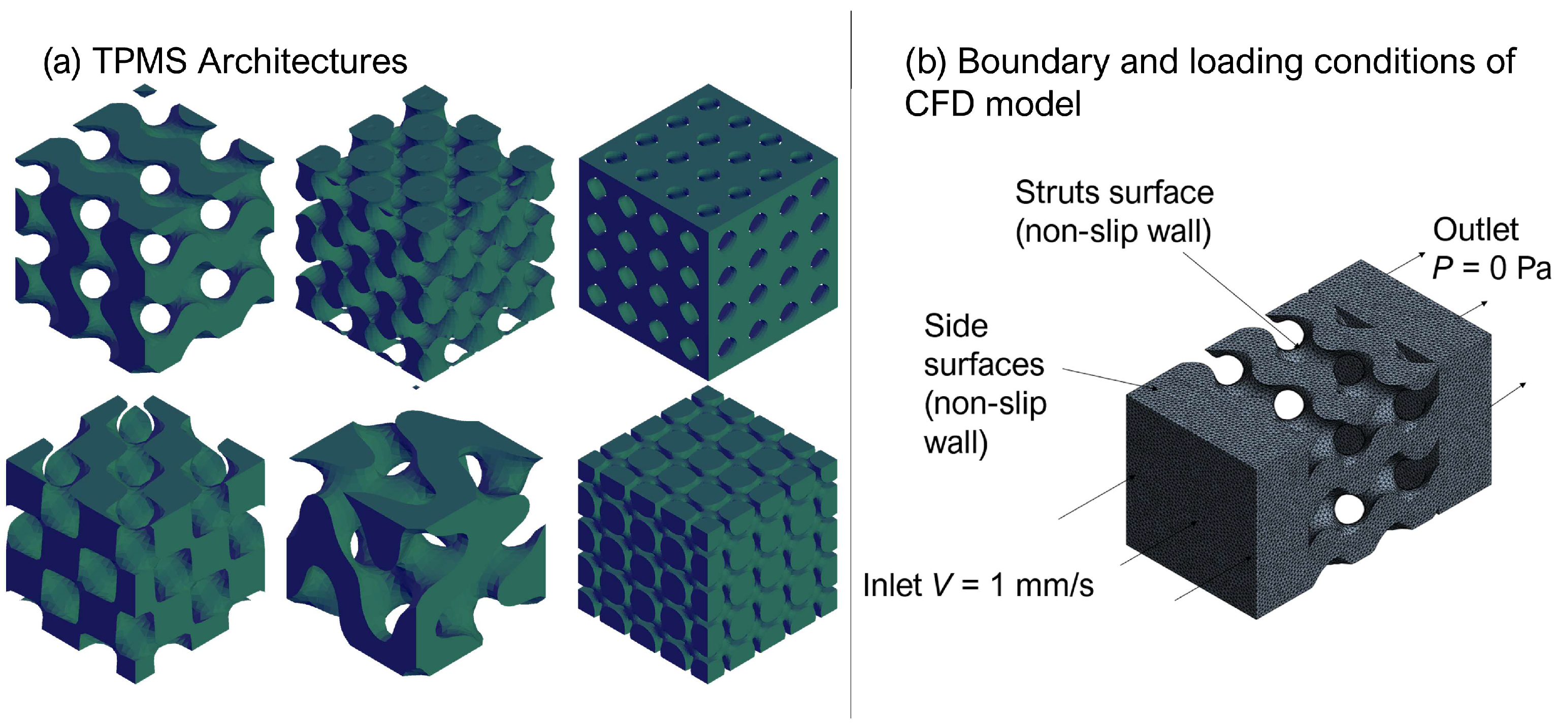
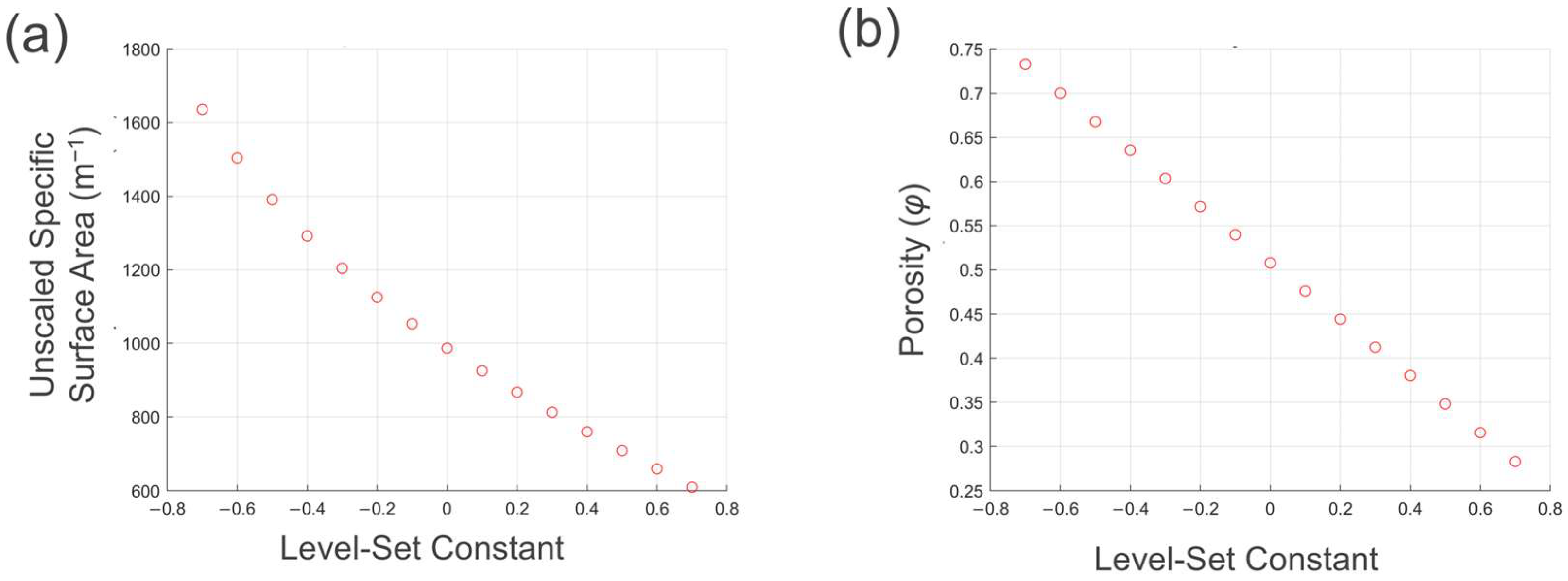
2.1. Topology Analysis

A first step in modifying the Kozeny–Carman equation by incorporating the level-set constant is to complete topology analysis on each of the TPMS structures. Relationships that relate porosity, pore size, and specific surface area to the level-set constant need to be determined. The 6 structures used in this study are the Gyroid, FKS, Primitive, Diamond, FRD and Neovius [14], whose topologies are shown in Figure 1a. FKS (Fischer Koch S) and F-RD (F-rhombic dodecahedra) are two of the lesser known TPMS structures; however, they have the two highest specific surface areas out of the 6 TPMS structures. Therefore, it is hypothesized that they will have high value as tissue engineering scaffolds [15]. TPMS structures can take one of two different forms of lattice: a ligament-based lattice and a sheet-based lattice. In a ligament-based lattice, the surface separates two volumes. One of these volumes is solidified and makes up the scaffold; the other volume makes up the void space of the scaffold. In a sheet-based lattice, two surface equations are used with different level-set constant values. The gap between these two surfaces is solidified, and this is used to make up the scaffold [16]. A previous study showed close similarity between experimental and simulation results for ligament-based TPMS lattices, whilst for sheet-based lattices, there was significant divergence between the study’s experimental and simulation results [17]. Therefore, in this study, we use ligament-based lattices for creating the TPMS geometries.
One method of generating these surfaces is to use level-set approximation equations, based on trigonometric functions. The gyroid surface is approximated by the following equation [18]:
ΦG(x,y,z) = cos(x)sin(y) + cos(y)sin(z) + cos(z)sin(x) − C,
where C is the level-set constant and calculates the surface when ΦG = 0. The level-set constant controls the pore morphology and therefore can be altered to change the initial pore size and porosity [19].
The level-set approximation is controlled by both the trigonometric functions and the level-set constant. By calculating the level-set equation (Equation (1)) at a given Cartesian coordinate, it can be determined whether that point is in the solid or void phase. If the sum of the trigonometric functions is greater than C, then Φ > 0, and the point is considered to be in the solid volume. If the sum is less than the value of C, then Φ < 0 and the point lies within the void space. As the value of the level-set constant is altered, the morphology of the surface changes, thus changing the ratio of coordinates on each side of the surface. This shows that there is a direct relationship between the level-set constant and the porosity of a TPMS scaffold. This relationship has already been estimated for the gyroid surface (Equation (2)) [20]. In a similar method, altering the level-set constant will change the morphology of the surface, changing the pore size of the structure. This relationship has also been identified for the gyroid surface (Equation (3)) [20]:
C = 0.7864φ3 − 1.1798φ2 − 2.5259φ + 1.4597,
dp = −11.7311C5 − 0.1307C4 − 1.7987C3 + 0.2070C2 − 186.9928 + 433.0114,
where φ is porosity and dp is the pore size of a structure prior to scaling. A structure can then be scaled to a specified pore size (dp) using the ratio of dp and dp.
Using a similar automatic method to Reference [20], level-set relationships were determined for the porosity, pore size, and unscaled specific surface area of each of the TPMS scaffolds. These relationships, along with the definitions of pore size for each TPMS structure, are given in the Supplementary Material. Specific surface area is a component of the Kozeny–Carman equation and is characterized as the wetted surface area of the scaffold divided by the bulk volume of the scaffold. Using these relationships and the Kozeny–Carman equation, code was written to test different 4π × 4π × 4π mm scaffolds to test how the level-set constant affects the geometric permeability. This scaffold size was chosen due to a volume dependency study to negate the boundary effects.

2.2. CFD Simulation to Determine Kozeny Constant β

To assess the accuracy of the Kozeny–Carman equation (Equation (5)) and the value of the Kozeny constant, β, 16 scaffolds were simulated using ANSYS CFX 2023 R2 (ANSYS Inc., Canonsburg, PA, USA) for each of the six TPMS architectures. The scaffolds ranged in porosity from 50 to 80% with 10% intervals, and for each porosity level there was a range of pore sizes from 400 to 700 μm with 100 μm intervals—this combination of four levels of porosity and four values for pore size giving 16 scaffolds for each architecture. The geometric inverse of the TPMS structures was extracted and used as the fluidic domain. The simulation setup was designed with a free fluid domain on opposite sides of each TPMS structure with an inlet velocity of 1 mm/s and a zero-pressure outlet applied to the end faces of the free-fluid domain with water as the medium. Non-slip walls were used on the other faces of the fluidic domain (Figure 1b). The fluid domains were imported as STL meshes, then regularized to a size of 50 μm, and then solidified (Figure 1b). Pressure–velocity coupling was used in CFX and was implemented using the Rhie–Chow algorithm [21]. The convergence criteria of root-mean-square residual of the mass and momentum is <1 × 10⁻⁴. All of the simulations were run on a computer with 128GB RAM and an Intel i7 12,700 CPU (12 cores).
The pressure drop was recorded from the inlet to the outlet of the scaffold region, and Darcy’s law was used to determine the absolute permeability. The absolute permeability was then divided by the geometric permeability determined from the Kozeny–Carman Equation (5) to calculate the Kozeny constant, β, for each of the individual scaffolds.

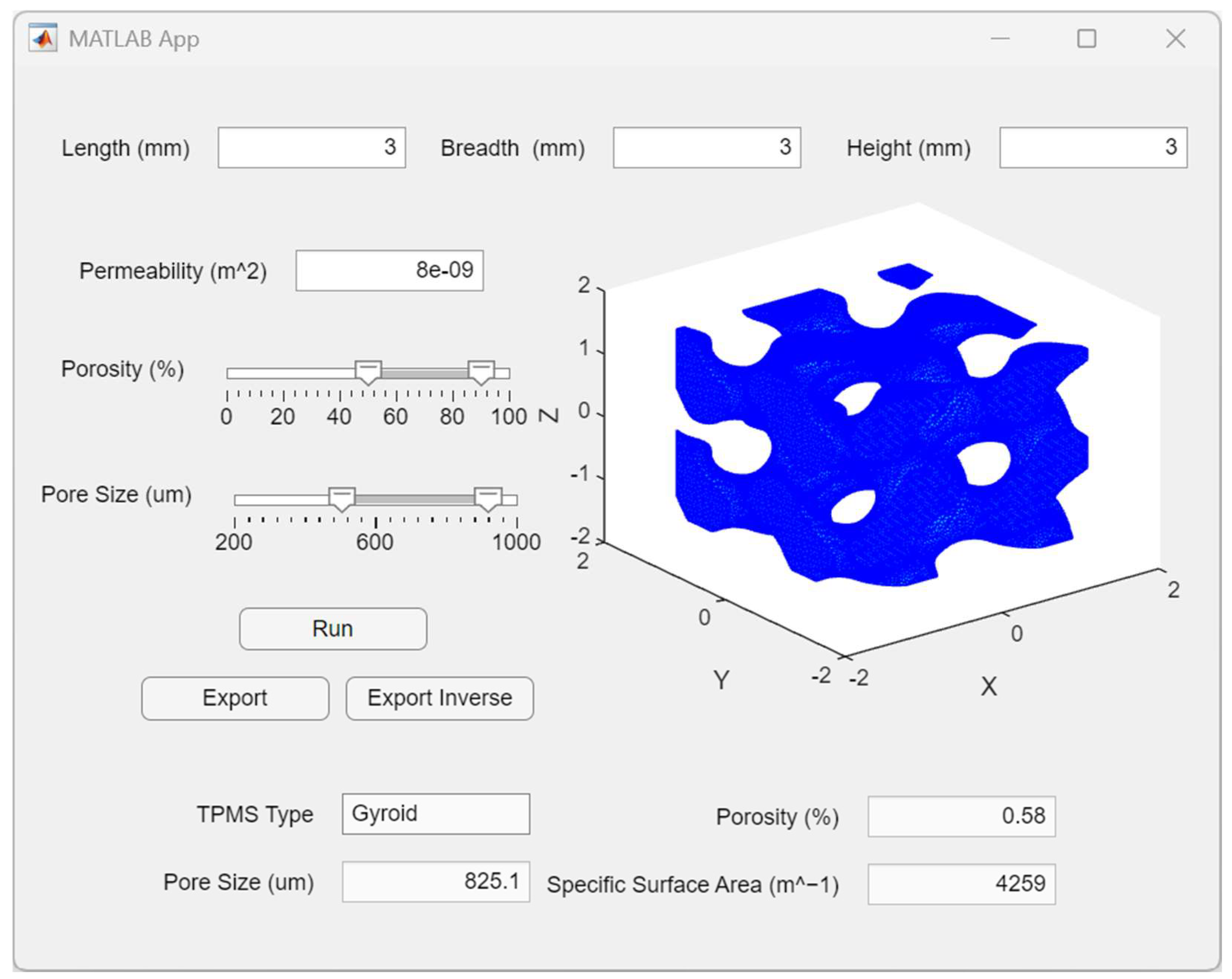
2.3. Development of Scaffold Design Toolbox

The toolbox functions following the flowchart seen in Figure 2. It uses the updated Kozeny–Carman equation to return values for porosity and pore size for each of the TPMS types. The ψ–level-set constant relationship (Equation (8)) is used to find values of pore size for input values of permeability, β, and porosity. This relationship is derived automatically within the toolbox for all 6 of the TPMS types. The user will be required to input a permeability and set the ranges for porosity and pore size. As can be seen in Figure 2, the toolbox will test 6 different porosities within the specified porosity range. The level-set constant of each of the different porosities is determined using Equation (2); the gyroid relationship is shown graphically in Figure 3b. The level-set constant (C) is then used to determine ψ using the equation from the fitting functions in Figure 4. Using permeability, ψ, and β, pore size can be determined using Equation (9). If any of the 6 tested porosities produces a pore size within the pore size range, the porosity, pore size, and TPMS type are recorded, and a scaffold is generated and then can be exported. If no pore sizes are found to be in the specified range, the program will run again with a different TPMS type. This process will repeat until an acceptable pore size is found or until all 6 TPMS types have been tested with a nil return.

3. Results

3.1. Updated Kozeny–Carman Equation

Figure 3a relates the level-set constant to the unscaled specific surface area of the gyroid, where decreasing the level-set constant increases the unscaled specific surface area. Figure 3b shows the relationship between porosity and the level-set constant for the gyroid surface. Similarly, decreasing the level-set constant increases the porosity. This is the inverse function of Equation (2). Because both porosity and the unscaled specific surface area are a function of the level-set constant, if the scale factor and the Kozeny constant are known, then an estimation of permeability can be determined.
S C , α = S 0 C α ,
Porosity and dp can be derived solely from the level-set constant, shown in Equations (2) and (3), and the unscaled specific surface area (S0) can also be derived from the level-set constant, shown in Figure 3a. This carries that the majority of variables that make up the Kozeny–Carman equation (Equation (5)) can be derived from the level-set constant. Thus, a variable (ψ) of the Kozeny–Carman equation was designed. This variable (ψ) incorporates all of the variables solely derived from the level-set constant. The equation of this variable is shown in Equation (8), and the graphical representation of ψ is shown in Figure 4. Equation (5) shows the Kozeny–Carman equation, and Equation (6) shows the combination of Equations (4) and (5). Equation (7) shows the scale factor, α, which is used to correct the pore size.
κ = β · φ 3 1 φ 2 · S 2 ,
κ = β · φ 3 ( 1 φ ) 2 · S 0 2 · α 2 ,
α = d p d p 2 π · 2 π ,
κ = β · ψ · d p 2 ψ ( C ) = φ ( C ) 3 · d p 2 π ( C ) · 2 π 2 1 φ ( C ) 2 · S 0 ( C ) 2 ,
d p = κ β · ψ
where ψ is the derived variable, β is the Kozeny constant, κ is the permeability, φ is the porosity, S0 is the unscaled specific surface area, S is the specific surface area, α is the scale factor, dp is the pore size of a structure prior to scaling, and dp is the specified pore size.
The results of CFD simulations are shown in Table 1, where the average Kozeny constant over the 16 variations for each TPMS architecture is given.
Table 1 indicates that all six TPMS types have β values close to 0.12. It is noteworthy that, although the primitive and Neovius structures have close geometric and visual similarities, they have different values for the Kozeny constant. This contrasts with the gyroid and FKS architectures, which are geometrically similar and also have the same β value. The typical value of β in the Kozeny–Carman equation was stated to have a value around ~0.2 [13]. The simulation results indicate that all the TPMS structures have significantly lower β values than 0.2.

3.2. MATLAB Toolbox for Scaffold Design

Based on the results of the porous geometry-influenced permeability above, a toolbox that can produce TPMS scaffolds based on a specified permeability have been developed in MATLAB R2023b (MathWorks, Netick, CA, USA), e.g., Figure 5 shows the user interface of the toolbox. The user will be required to enter the overall dimensions of the scaffold, the ranges for porosity and pore size, and the desired permeability. The ranges of porosity and pore size are important to enter, as the pore size and porosity of TPMS structures are highly reliant on appropriate manufacturing methods. The ‘export’ button will generate an STL file of the scaffold structure, which can then be used in 3D printing software, and the ‘export inverse’ button will generate an STL file of the geometric inverse, which can then be imported into a simulation software. The function for writing STL files was downloaded from the MATLAB Online file exchange [22].

4. Discussion

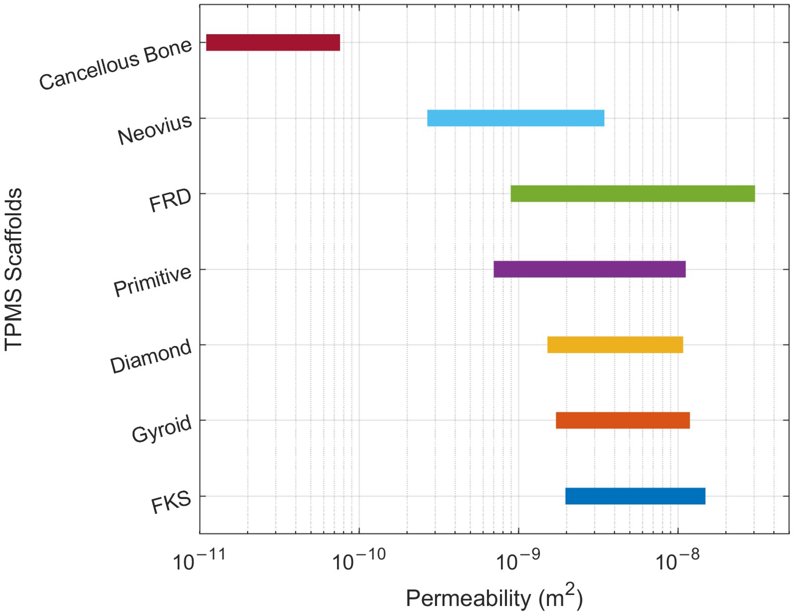
4.1. Permeability Comparison of TPMS Architectures

The values of β (Table 1) for each TPMS architecture were inputted into the toolbox, and this enabled the calculation of accurate permeabilities. Figure 6 shows the ranges of calculated permeabilities for both the lowest permeability for each TPMS architecture (pore size 400 μm and porosity 50%) and the highest permeability (pore size 700 μm and porosity 80%). From Figure 6, it can be seen that each of the scaffolds produces a higher permeability than cancellous bone [23]. This is expected, since TPMS structures have high permeabilities due to their low constriction factor, which, in turn, is due to their repeating units and their comparatively lower tortuosity. Another interesting observation from Figure 6 is the length of the ranges of the generatable permeabilities of the TPMS scaffolds. The F-RD, Neovius, and primitive scaffolds all have broader permeability ranges than the gyroid, diamond, and FKS scaffolds. The F-RD architecture also seems to have a significantly larger range of generatable permeabilities, allowing for the highest permeability to be produced. Additionally, it would seem that the Neovius structure is unique among the six scaffolds because of its lower range of generatable permeabilities, allowing for structures to be generated with permeabilities that are closer to that of cancellous bone. Because homogenous TPMS structures have lower constriction factors (leading to higher permeabilities), it is hypothesized that heterogenous-gradient TPMS structures could be used to achieve scaffold permeabilities even closer to that of cancellous bone.

4.2. Limitations and Future Work

The simulation results indicate that the Kozeny–Carman equation, with the Kozeny constant (β) included, is an accurate way to estimate the permeability. This work has also shown that this Kozeny–Carman equation can be derived further into Equation (9), where the permeability can be determined through pore size, the Kozeny constant, and the new variable described in this paper. However, one major limitation of this method is that β was not constant for each TPMS architecture; decreasing pore size caused higher values of β. The variation in the value of β was negligible for five of the six TPMS architectures; however, using the same value of β for the F-RD architecture may cause slight inaccuracies in the calculated permeability. This work has also determined the relationship between specific surface area and the level-set constant, which was previously unknown, furthering the work of Walker et al., 2017.
Since the process for determining this new variable is automated, this constant could be determined for other common TPMS structures such as the lidinoid, CLP, or IWP. These structures could in future be implemented into the toolbox, if the range of attainable permeabilities needs to be increased. A further way to attain a larger range of permeabilities could be to include sheet-based lattices of the already available TPMS structures within the toolbox. This would first require new constant values and new level-set relationships to be determined. As described previously, heterogenous gradient TPMS structures could be used to achieve permeabilities closer to cancellous bone; both porosity and pore size gradients result in higher constriction factors and so should be tested in future. Additionally, combination TPMS structures would also result in a higher constriction factor and thus a lower permeability.

5. Conclusions

In this study, the Kozeny–Carman equation, which is used for calculating the permeability of porous material, has been updated for calculating the permeability of tissue engineering scaffolds with TPMS architectures. Based on this, a design toolbox has been developed which allows for the efficient generation of TPMS scaffolds with a tailored permeability. This will allow for tissue engineers to design and manufacture tissue engineering scaffolds with precisely controlled permeability.

Supplementary Materials

The following supporting information can be downloaded at: https://www.mdpi.com/article/10.3390/jmmp9030072/s1.

Author Contributions

Conceptualization, M.B.-T. and F.Z.; methodology, M.B.-T.; software, M.B.-T.; validation, M.B.-T. and F.Z.; formal analysis, M.B.-T.; investigation, M.B.-T.; data curation, M.B.-T.; writing—original draft preparation, M.B.-T.; writing—review and editing, F.Z., B.S., and P.N.; visualization, M.B.-T.; supervision, F.Z.; project administration, F.Z.; funding acquisition, F.Z. All authors have read and agreed to the published version of the manuscript.

Funding

This study was supported by EPSRC–Doctoral Training Partnership (DTP) scholarship (reference code: EP/T517987/1-2573181), and the Royal Society research grant (reference code: RGS\R2\212280).

Data Availability Statement

The data that support the findings of this study are available from the corresponding author upon reasonable request.

Conflicts of Interest

The authors declare no conflicts of interest.

References

  1. Zhao, F.; van Rietbergen, B.; Ito, K.; Hofmann, S. Flow rates in perfusion bioreactors to maximise mineralisation in bone tissue engineering In Vitro. J. Biomech. 2018, 79, 232–237. [Google Scholar] [CrossRef] [PubMed]
  2. Frantz, C.; Stewart, K.M.; Weaver, V.M. The extracellular matrix at a glance. J. Cell Sci. 2010, 123, 4195–4200. [Google Scholar] [CrossRef] [PubMed]
  3. Dong, Z.; Zhao, X. Application of TPMS structure in bone regeneration. Eng. Regen. 2021, 2, 154–162. [Google Scholar] [CrossRef]
  4. Sokollu, B.; Gulcan, O.; Konukseven, E.I. Mechanical Properties Comparison of Strut-Based and Triply Periodic Minimal Surface Lattice Structures Produced by Electron Beam Melting. Addit. Manuf. 2022, 60, 103199. [Google Scholar]
  5. Lehder, E.F.; Ashcroft, I.A.; Wildman, R.D.; Ruiz-Cantu, L.A.; Maskery, I. A multiscale optimisation method for bone growth scaffolds based on triply periodic minimal surfaces. Biomech. Model. Mechanobiol. 2021, 20, 2085–2096. [Google Scholar] [CrossRef] [PubMed]
  6. Castro, A.P.G.; Pires, T.; Santos, J.E.; Gouveia, B.P.; Fernandes, P.R. Permeability versus design in TPMS scaffolds. Materials 2019, 12, 1313. [Google Scholar] [CrossRef] [PubMed]
  7. Ochoa, I.; Sanz-Herrera, J.A.; García-Aznar, J.M.; Doblaré, M.; Yunos, D.M.; Boccaccini, A.R. Permeability evaluation of 45S5 Bioglass®-based scaffolds for bone tissue engineering. J. Biomech. 2009, 42, 257–260. [Google Scholar] [CrossRef] [PubMed]
  8. Zhao, F.; Xiong, Y.; Ito, K.; van Rietbergen, B.; Hofmann, S. Porous Geometry Guided Micro-mechanical Environment Within Scaffolds for Cell Mechanobiology Study in Bone Tissue Engineering. Front. Bioeng. Biotechnol. 2021, 9, 736489. [Google Scholar] [CrossRef] [PubMed]
  9. Berg, C.F. Permeability Description by Characteristic Length, Tortuosity, Constriction and Porosity. Transp. Porous Media 2015, 107, 713–726. [Google Scholar] [CrossRef]
  10. Rabbani, A.; Jamshidi, S. Specific surface and porosity relationship for sandstones for prediction of permeability. Int. J. Rock Mech. Min. Sci. 2014, 71, 25–32. [Google Scholar] [CrossRef]
  11. Mauri, A.; Bertola, M. Alvascience: A New Software Suite for the QSAR Workflow Applied to the Blood–Brain Barrier Permeability. Int. J. Mol. Sci. 2022, 23, 12882. [Google Scholar] [CrossRef] [PubMed]
  12. Zhang, H.L.; Yu, H.; Yuan, X.H.; Xu, H.Y.; Micheal, M.; Zhang, J.N.; Shu, H.L.; Wang, G.C.; Wu, H.A. Permeability prediction of low-resolution porous media images using autoencoder-based convolutional neural network. J. Pet. Sci. Eng. 2022, 208, 109589. [Google Scholar] [CrossRef]
  13. The Carman-Kozeny Equation. Available online: https://www.doitpoms.ac.uk/tlplib/powder/carman.php (accessed on 22 May 2024).
  14. Blanquer, S.B.G.; Werner, M.; Hannula, M.; Sharifi, S.; Lajoinie, G.P.R.; Eglin, D.; Hyttinen, J.; Poot, A.A.; Grijpma, D.W. Surface curvature in triply-periodic minimal surface architectures as a distinct design parameter in preparing advanced tissue engineering scaffolds. Biofabrication 2017, 9, 025001. [Google Scholar] [CrossRef] [PubMed]
  15. Knödler, P.; Dreissigacker, V. Fluid Dynamic Assessment and Development of Nusselt Correlations for Fischer Koch S Structures. Energies 2024, 17, 688. [Google Scholar] [CrossRef]
  16. Abou-Ali, A.M.; Lee, D.W.; Abu Al-Rub, R.K. On the Effect of Lattice Topology on Mechanical Properties of SLS Additively Manufactured Sheet-, Ligament-, and Strut-Based Polymeric Metamaterials. Polymers 2022, 14, 4583. [Google Scholar] [CrossRef] [PubMed]
  17. Abou-Ali, A.M.; Al-Ketan, O.; Lee, D.W.; Rowshan, R.; Abu Al-Rub, R.K. Mechanical behavior of polymeric selective laser sintered ligament and sheet based lattices of triply periodic minimal surface architectures. Mater. Des. 2020, 196, 109100. [Google Scholar] [CrossRef]
  18. Zou, S.; Mu, Y.; Pan, B.; Li, G.; Shao, L.; Du, J.; Jin, Y. Mechanical and biological properties of enhanced porous scaffolds based on triply periodic minimal surfaces. Mater. Des. 2022, 219, 110803. [Google Scholar] [CrossRef]
  19. Lu, C.; Zhang, Y.; Aziz, M.; Wen, P.; Zhang, C.; Shen, Q.; Chen, F. Mechanical behaviors of multidimensional gradient gyroid structures under static and dynamic loading: A numerical and experimental study. Addit. Manuf. 2022, 59, 103187. [Google Scholar] [CrossRef]
  20. Walker, J.M.; Bodamer, E.; Kleinfehn, A.; Luo, Y.; Becker, M.; Dean, D. Design and mechanical characterization of solid and highly porous 3D printed poly(propylene fumarate) scaffolds. Prog. Addit. Manuf. 2017, 2, 99–108. [Google Scholar] [CrossRef]
  21. Ansys CFX-Pre User’s Guide. 2021. Available online: https://dl.cfdexperts.net/cfd_resources/Ansys_Documentation/CFX/Ansys_CFX-Solver_Theory_Guide.pdf (accessed on 17 February 2025).
  22. Sven. Stlwrite-Write ASCII or Binary STL Files. MATLAB Central File Exchange. 2025. Available online: https://www.mathworks.com/matlabcentral/fileexchange/20922-stlwrite-write-ascii-or-binary-stl-files (accessed on 11 January 2025).
  23. Prakoso, A.T.; Basri, H.; Adanta, D.; Yani, I.; Ammarullah, M.I.; Akbar, I.; Ghazali, F.A.; Syahrom, A.; Kamarul, T. The Effect of Tortuosity on Permeability of Porous Scaffold. Biomedicines 2023, 11, 427. [Google Scholar] [CrossRef] [PubMed]
Figure 1. (a) Six TPMS architectures: gyroid, F-RD, primitive, diamond, FKS, Neovius (from top left to bottom right). (b) CFD simulation setup to determine Kozeny constant β.
Jmmp 09 00072 g001
Figure 2. Flow chart for the process in which a scaffold is generated.
Jmmp 09 00072 g002
Figure 3. (a) Level-set constant vs. unscaled specific surface area for scaffolds, (b) level-set constant vs. porosity for scaffolds.
Jmmp 09 00072 g003
Figure 4. Relationship between level-set constant and ψ for gyroid structure by curve fitting.
Jmmp 09 00072 g004
Figure 5. Screenshot of toolbox where a gyroid scaffold has been generated using a permeability input of 8 × 10⁻⁹ m2 and geometric inputs of 3 mm in each direction.
Jmmp 09 00072 g005
Figure 6. Range of permeabilities for TPMS scaffolds with comparative cancellous bone.
Jmmp 09 00072 g006
Table 1. Average Kozeny constant for each TPMS type.
TPMS TypeGyroidDiamondFKSFRDPrimitiveNeovius
β0.12 ± 0.0210.13 ± 0.0220.12 ± 0.0190.17 ± 0.0190.15 ± 0.0320.12 ± 0.032
Disclaimer/Publisher’s Note: The statements, opinions and data contained in all publications are solely those of the individual author(s) and contributor(s) and not of MDPI and/or the editor(s). MDPI and/or the editor(s) disclaim responsibility for any injury to people or property resulting from any ideas, methods, instructions or products referred to in the content.

