Review

A Review of Friction Stir Welding of Industrial Alloys: Tool Design and Process Parameters

by
Vincenzo Lunetto
1,2,*,
Manuela De Maddis
1,2,
Franco Lombardi
1,2 and
Pasquale Russo Spena
1,2
1
Department of Management and Production Engineering, Politecnico di Torino, Corso Duca degli Abruzzi 24, 10129 Torino, Italy
2
Advanced Joining Technologies Center (J-Tech@PoliTO), Politecnico di Torino, Corso Duca degli Abruzzi 24, 10129 Torino, Italy
*
Author to whom correspondence should be addressed.
J. Manuf. Mater. Process. 2025, 9(2), 36; https://doi.org/10.3390/jmmp9020036
Submission received: 25 December 2024 / Revised: 17 January 2025 / Accepted: 21 January 2025 / Published: 28 January 2025
(This article belongs to the Special Issue Advances in Welding Technology)

Abstract

:
Friction stir welding (FSW) is a pivotal technology with ongoing relevance across industries. Renowned for its ability to join materials with dissimilar melting points while mitigating thermal distortions, FSW offers relevant advantages over traditional fusion welding. However, the adoption of FSW for high-strength alloys poses notable challenges, including: (i) accelerated tool wear, (ii) the need for special tool features tailored to these alloys, and (iii) a narrow process window. This review provides a comprehensive overview of FSW as an advanced technique for joining metal alloys for several industrial fields. Emphasis is on materials such as Mg-, Cu-, Ti-, and Ni-based alloys, automotive steels, stainless steels, and maraging steels. The research highlights the critical influence of tool design—main dimensions, features, and materials—and process parameters—rotational and welding speeds, tilt angle, and plunge depth or vertical load—also considering their influences on defect formation. Detailed insights are provided into material flow and the formation of the different weld regions, including SZ, TMAZ, and HAZ.

1. Introduction

Friction Stir Welding (FSW), developed by The Welding Institute (TWI) in the early 1990s and patented as “Friction welding, US5460317A”, represents an innovative advancement in both welding processes and tool design [1]. FSW offers several advantages, due to its reduced heat input, resulting in minimal joint distortions and residual stresses [2,3]. FSW is particularly valuable for several applications, and also for joining additively manufactured alloys like Scalmalloy® [4,5], where its low heat input minimizes detrimental effects on the microstructure and preserves strength, making it suitable for demanding structural applications [4,5]. FSW is highly effective for joining materials with different melting points and chemical incompatibilities, such as steel to aluminum alloys [6], titanium to magnesium alloys [7], and polymer composites to aluminum alloys [8]. In addition, friction-stir-based processes, including active/passive filling friction stir repair (AF/PF-FSR), are effective for repairing structural defects in high-melting-point alloys. These techniques restore mechanical integrity while minimizing the adverse effects of melting, making them particularly suitable for aerospace and automotive applications [9]. Furthermore, FSW is environmentally friendly, since it requires less energy and produces lower gas emissions compared to other thermal welding technologies and manufacturing processes [10,11].
FSW uses a rotating non-consumable tool consisting of a shoulder and a pin, both specifically designed and tailored in dimensions and features to suit the specific application. In a butt-joint configuration, Figure 1a, the tool plunges into the materials to be joined, with the pin (nearly) reaching their lower surfaces. In a lap-joint configuration, the tool plunges the upper part, while only the pin penetrates the lower one, Figure 1b. About 70% of heat is generated by the frictional action between the shoulder and the material, facilitating the mixing of the joint interface and ensuring a smoother transition in joint properties [12]. The pin favors these actions, through a mechanical mixing along the material thickness, ensuring uniform joint quality. FSW tool designs—such as those featuring scrolled shoulder, threaded pin, tapered pin, tri-flute pin [12]—are carefully tailored based on the material, thickness, and joint configuration. Key process parameters include (i) rotational speed (ii), welding speed, (iii) tilt angle, and (iv) plunge depth (in position-control mode) or vertical force (in force-control mode). Additional parameters more related to the initial plunging phase, such as (v) plunge speed and (vi) dwell time, also significantly influence the welding process. FSW accommodates a variety of joint configurations, including butt, edge butt, fillet, lap, t-butt, and t-lap joints. Due to the high torque and forces involved, FSW demands sophisticated clamping and fixing systems compared to traditional welding techniques, like arc or laser welding, ensuring process stability and precision.
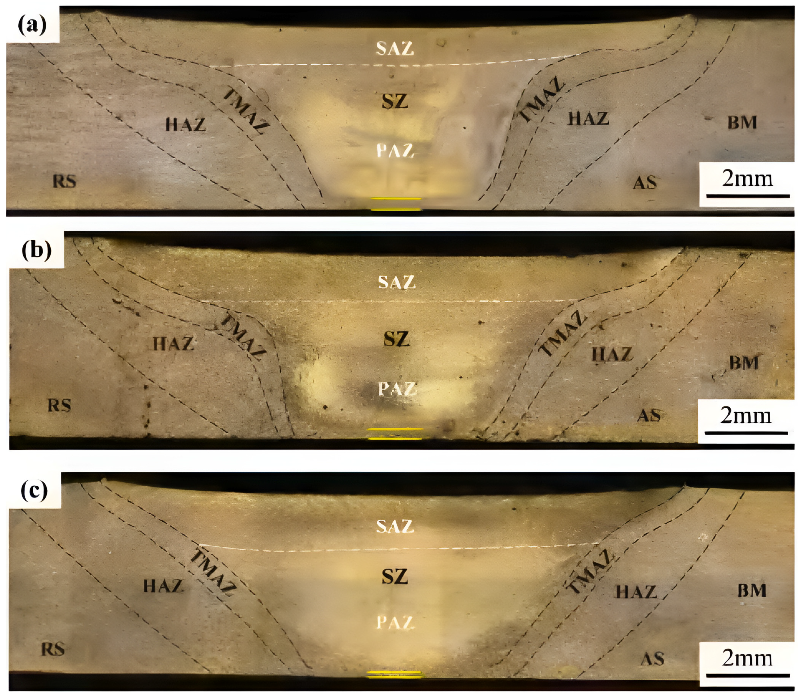
FSW joints exhibit an asymmetrical geometry relative to the tool axis, as illustrated in Figure 1. The advancing side (AS) forms where the tool rotational direction aligns with the welding travel direction, resulting in a concordance of speeds. Conversely, the retracting side (RS) occurs where the tool rotational direction opposes the welding travel direction. Distinct microstructural zones develop within an FSW joint. Figure 2 shows examples of cross-sections and the characteristic regions of an FSW joint in a butt (Scalmalloy®, 4 mm thick [4]) and a lap (Ti6Al4V, 2 mm thick [13]) configuration. The stir zone (SZ) is the central region where the tool actively stirs and consolidates the material. Intense plastic deformation combined with heat input induces substantial grain refinement, reducing grain size to approximately 3–5 μm. This refinement results in a more uniform and fine-grained microstructure [4]. In addition, the stirring and mixing actions of FSW effectively reduce porosity in materials with microstructures originating from additive manufacturing or casting processes. For instance, Abankar et al. [14] performed 3D X-ray computed tomography on FSW butt joints of additively manufactured A20X, demonstrating that the stirring action notably reduced intrinsic pore equivalent diameter from an initial range of 55–150 µm in the base material (BM) to values below 55 µm in the SZ. Similarly, Orlando et al. [15] showed that FSW could eliminate the dendritic structures and eliminate porosity of GMAW joints between cast and extruded aluminum alloys.
The thermomechanical-affected zone (TMAZ) experiences both heat and mechanical deformation. In Figure 2a, the significant changes in the original microstructure of Scalmalloy® and the pronounced grain deformation along the stirring direction can be observed [4]. Under specific conditions, the TMAZ may not be well-defined or easily observable [13]. At low rotational speeds, the stirring generated in the SZ dissipates rapidly into the BM. As a result, the extent of the mechanical deformation outside the SZ is minimal, leading to a less distinct or even negligible TMAZ. Materials with a high strength-to-mass ratio are inherently more rigid and resistant to deformation. This rigidity makes it more difficult to produce the characteristic grain strain in the TMAZ along the direction of tool rotation, thereby reducing its observability and/or extent. In addition, materials with low thermal conductivity exhibit steep thermal gradients between the SZ and the BM. These gradients limit thermal diffusion, which is essential for softening the material and facilitating plastic deformation, contributing to a narrower or less noticeable TMAZ, Figure 2b. The heat-affected zone (HAZ) experiences high temperatures that cause microstructural changes, such as phase transformations, grain growth, and/or second-phase precipitation, without reaching the melting point. The BM, instead, remains unaltered by the heat input involved during the welding process, preserving its original microstructure.

1.1. Aim and Structure of the Review

This study investigates FSW of key industrial materials, including Mg alloys, Cu alloys (such as brass and bronze), and first-generation automotive steels, highlighting its potential to enhance weld properties. It also addresses the challenges associated with joining alloys that feature high melting points, outstanding mechanical properties, and rapid tool wear. The investigation further extends to second- and third-generation automotive steels, different stainless steel grades (austenitic, ferritic, duplex, and martensitic), maraging steels, and Ni alloys (primarily Inconel). The research systematically explores the critical influence of tool design (dimensions, features, and materials) and process parameters (rotational speed, welding speed, tilt angle, plunge depth/vertical load) on weld quality. In addition, the study examines material flow and the formation of weld regions, such as the SZ, TMAZ, and HAZ. The review addresses defect formation across various alloys and proposes strategies for its mitigation. Aluminum alloys are intentionally excluded from this review, as their FSW applications are extensively documented and deserve a dedicated study.
The paper is organized into four sections:
  • Fundamentals of FSW—an overview of the process, alloy selection criteria, and research methodology;
  • Process parameters and tool design—a detailed list of tool dimensions and features, and process parameters across different materials;
  • Tool design and process windows—an analysis and discussion of tool dimensions, features, materials, and process windows relative to alloy thickness;
  • Conclusions and future trends—a summary of findings and identification of promising areas for future research.

1.2. Review Methodology

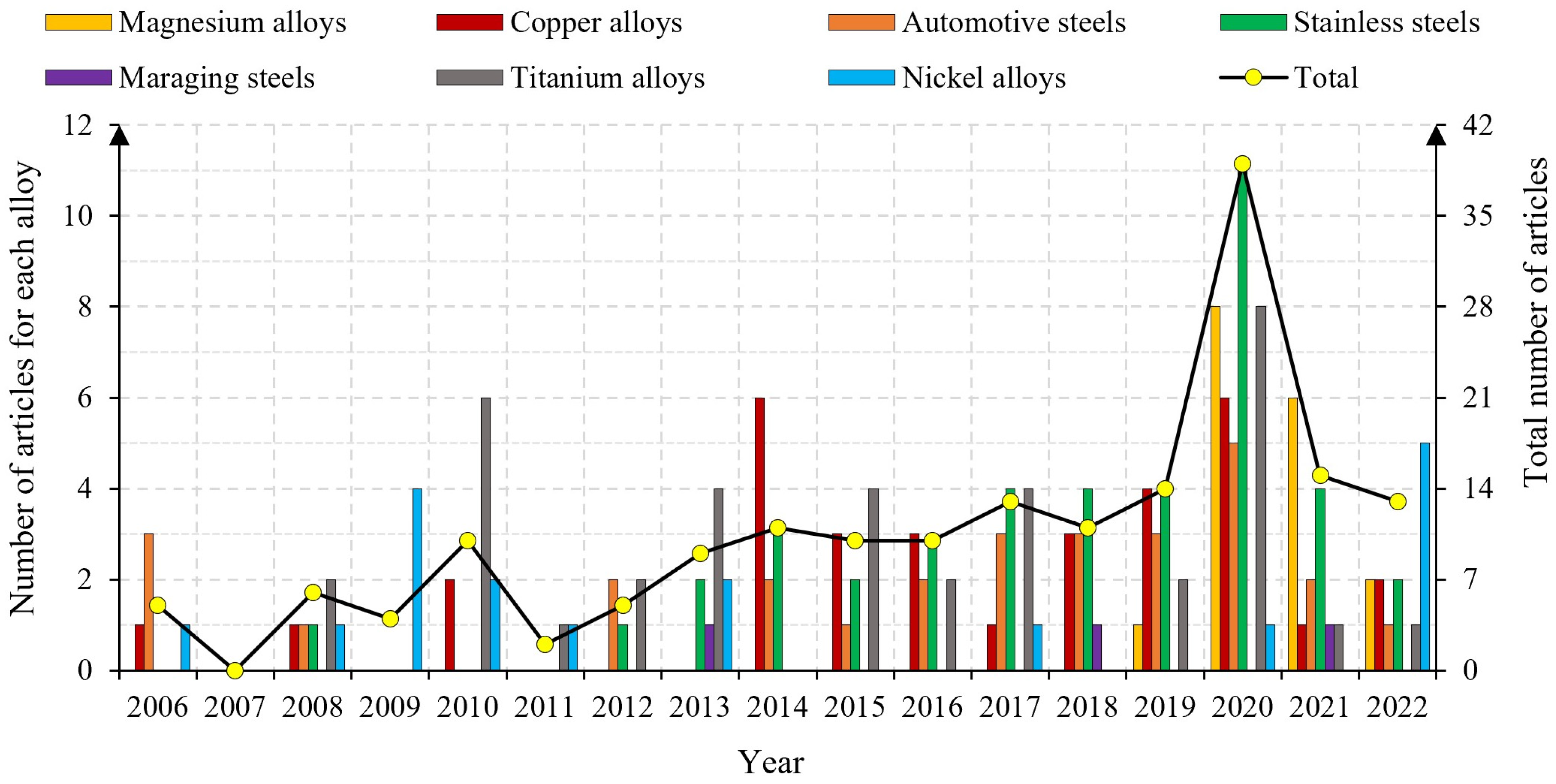
A total of 177 papers were collected from the Scopus database for this study, comprising 161 journal articles (91%), 3 books or book chapters (2%), and 13 conference papers (7%). These resources provide critical information on process parameters and tool design, enabling a comprehensive analysis of the subjects covered in this review. The number of papers examined for each investigated alloy is as follows: 17 for Mg alloys, 33 for Cu alloys, 28 for automotive steels, 41 for stainless steels, 3 for maraging steels, 37 for Ti alloys, and 18 for Ni alloys. A breakdown of automotive steels reveals 18 publications for first-, 4 for second-, and 6 for third-generation steels. For stainless steels, resources include 16 publications on austenitic, 13 on duplex, 5 on ferritic, 2 on martensitic, and 5 addressing dissimilar stainless steel joints. Notably, some austenitic grades, used in the automotive industry as second-generation automotive steels, were not classified under the automotive group in this review. Figure 3 shows the distribution of these articles by year of publication. The majority of the reviewed papers focus on butt-joint configuration. Only seven studies investigate lap-joint configurations, while just one study examines a T-joint configuration.

2. Data Inventory: Process Parameters and Tool Design

This section details materials, dimensions, and design features of tools used in FSW, as compiled from the reviewed studies across different alloys: Mg alloys (Table 1), Cu alloys (Table 2), automotive steels (Table 3), stainless steels (Table 4), maraging steels (Table 5), Ti alloys (Table 6), and Ni alloys (Table 7). The tables also report key process parameters, including rotational speed (denoted as “ω”), welding speed (“v”), tilt angle (TA), plunge depth (PD), and vertical load (VL). The tilt angle is described as positive when the shoulder penetration is greater on the trailing side (TS) of the joint, as shown in Figure 1, and negative when the shoulder penetration is prevalent on the leading side (LS).
The following legend clarifies the abbreviations used in the tables: BD—base diameter; Co—convex; Cy—cylindrical; F—flat; He—hemispherical; PL—pin length; S—spiral; T—tapered (total cone angle); TFLA—tri-flate; TFLU—tri-flute; B—butt-joint configuration; L—lap-joint configuration; Nu—numerical simulation included; PD—plunge depth; TA—tilt angle; Tj—T-joint configuration; VL—vertical load.
Tool materials frequently have a Co binder phase in WC tools to improve ductility and minimize the risk of failure [16]. Information about binder phase is included in the tables when provided in the reviewed papers.
The features of the FSW tools are classified as follows: (1) shoulder features “Co”, “F”, “S”, and “T”; (2) pin features “Cy”, “He”, “S”, “T”, “TFLA”, and “TFLU”. For clarity, Figure 4 shows the shoulder features “Co”, “F”, and “T” (also referred to as “concave” in the literature [17]), as well as the pin features “He”, “TFLA”, and “TFLU”.
The plunge depth refers to the extent of pin penetration into the joint, measured from the upper surface of the workpiece.
In Table 1, Table 2, Table 3, Table 4, Table 5, Table 6 and Table 7, a superscript symbol preceding a numerical value denotes a specific pairing rule. Values sharing the same superscript symbol within a column are sequentially paired with corresponding values in the adjacent column bearing the same superscript symbol, ensuring precise mapping of parameters.
Table 1. FSW of Mg alloys: process and tool parameters. Values sharing the same superscript (, , ) in a column are paired with corresponding values in the adjacent column. * Additional information not provided.
Materials, Thick. [mm]Tool MaterialTool Geometry [mm]Process Parameters [rpm, mm/min]NotesRef.
ShoulderPinRotational SpeedWelding Speed
Comm. pure, B, 3H1315, FPL: 2.8, BD: 6, Cy1700100TA: 3[18]
Comm. pure, B, 5N.A.16, CoPL: 4.8, BD: 5, Cy1000, 1500200TA: 3[19]
AZ31, B, 2N.A.13, F, SPL: 1.8, BD: 5, T, S, TFLA20002000TA: 0.5[20]
AZ31B, B, 4H1315, FPL: 3.8, BD: 5.4, T(24)80030TA: 2.5, PD: 3.95[21]
AZ31, B, 4HSS14, FPL: 3.8, BD: 4, Cy750, 150047.5 [22]
AZ31B, B, 5N.A.15, *PL: 4.7, BD: 6, T(30), S, TFLA130050TA: 2.5, PD: 4.8[23]
AZ31B, B, 6H1318, F, SPL: 5.7, BD: 10, T(63), S80050TA: 0, 2[24]
AZ61A, B, 6High C-Cr steel24, FPL: 5.7, BD: ~5, Cy, S1600, 1800, 200020, 40 [25]
AZ61, AZX612, B, 3H1315, T(160)PL: 2.8, BD: 5, Cy, S600500TA: 3[26]
AZ91, B, 4H1318, FPL: 3.8, BD: 6, Cy, S, TFLU140025 [27]
LZ91, B, 3SKD61, WC15, FPL: 2.8, BD: 6, Cy 50, 100, 200, 300, 300 50, 50, 100, 200TA: 3[28]
AM20, B, 4H1324, FPL: 3.5, BD: 6, Cy, S600, 815, 110063PD: 3.62[29]
ZE41, B, 5High C steel15, FPL: 4, BD: 5, Cy660, 122040TA: 2.5, VL: 5[30]
AZ31—AM60, B, 5N.A.15, FPL: 4.78, BD: 6, T(29), S 800, 1600 100, 600TA: 2.5[31,32]
AZ80A—AZ91C, B, 5HSS15, FPL: 4.75, BD: ~5, T(12)500, 750, 100075 [33]
AZ31—AZ91, B, 6.35H13(a) 15, 21, (b) 18, FPL: ~6, BD: 6, Cy, S(a) 850, 700, 1000, (b) 700, 1000, 850 30, 50, 40TA: 2.5[34]
Table 2. FSW of Cu alloys: process and tool parameters. Values sharing the same superscript (, , , ±) in a column are paired with corresponding values in the adjacent column. * Additional information not provided.
Materials, Thick. [mm]Tool MaterialTool Geometry [mm]Process Parameters [rpm, mm/min]NotesRef.
ShoulderPinRotational SpeedWelding Speed
Comm. pure, B, 2WC-Co12, FPL: 1.8, BD: 4, Cy400, 500, 600, 700, 800, 900, 1000200TA: 3, VL: 15[35]
Comm. pure (3N), B, 2WC12, CoPL: 1.9, BD: 4, Cy800150TA: 3, VL: 15[36]
Comm. pure, B, 3HSS12, CoPL: 2.85, BD: 3, Cy, S60025, 50, 100, 150, 200 [37]
Comm. pure (DHP), B, 3N.A.20, FPL: 2.8, BD: 4, T(20) 800, 1000, 1200 90, 150, 90, 120, 150, 90, 150 [38]
Comm. pure (C11000), B, 3N.A.16, FPL: 2, BD: 3, Cy1250, 160020TA: 2.5[39]
Comm. pure, B, Nu, 3WC-Co18, FPL: 2.9, BD: 6.2, T(53)1225, 1535, 1842, 200030TA: 0, VL: 5.3[40]
Comm. pure (C11000), B, 3.1HSS12, FPL: 2.8, BD: 3.75, T(15) 800, 900 30, 50PD: 2.85[41]
Comm. pure, B, Nu, 4H1311.5, FPL: 3.7, BD: 5, Cy, S90080, 100, 125, 150 [42]
Comm. pure, B, 4Steel for tools12, CoPL: 1.7, BD: 4, Cy, S200, 300, 400, 500, 600, 800, 1000120TA: 3, PD: 1.75[43]
Comm. pure, B, 5N.A.20, FPL: 4.7, BD: 8, Cy, S 500, 710 56, 112, 56TA: 2.5, PD: 4.9[44]
Comm. pure (ETP R220), B, 5N.A.23, Co, SPL: 4.5, BD: 8, T(32), S58040, 60, 80TA: 0, PD: 4.8[45]
0.7Ni–0.3Cr–0.12Fe–0.04Ti, wt.%, B, 4Pin: WC; Shoulder: HSS17.8, FPL: 3.5, BD: 6.5, Cy 630, 710 40, 40, 63TA: 1.5, PD: 3.8[46]
Brass C44300, B, 2N.A.12, *PL: 1.8, BD: 4, *800150TA: 3, VL: 9.8[47]
Brass Cu-30Zn, B, N.A.Steel for tools12, CoPL: 1.7, BD: 4, Cy, S200, 300, 400, 500, 600120TA: 3, PD: 1.75[48]
Brass Cu-30Zn, B, 2WC12, FPL: 1.9, BD: 4, Cy600200TA: 3, VL: 15[49]
Brass Cu-30Zn, B, 2WC12, CoPL: 1.9, BD: 4, Cy800200TA: 3, VL: 8[50]
Brass Cu-30Zn, B, 2WC-Co12, FPL: 1.8, BD: 4, Cy600200VL: 12[51]
Brass Cu-30Zn, B, 3Steel for tools13, FPL: 2.9, BD: ~5, Cy, S205020, 40, 56, 80, 112, 140TA: 0[52]
Brass Cu-37Zn, B, 2H1312, FPL: 1.75, BD: 3, Cy 800, 800, 600, 1000, ± 463, 1136 100, 16, 184, 50, 150, ± 100VL: 1.7, 2.5, 3.3, 2.5, 2, 3, ± 2.5[53]
Brass Cu-37Zn, B, 4Pin: HSS; Shoulder: Steel for tools20, FPL: 3.8, BD: 6, T(30), S 750, 1000 20, 20, 40, 60TA: 2, PD: 4[54]
Brass Cu-38Zn, B, 5N.A.18, FPL: 4.7, BD: 6, Cy, S400, 600, 800, 1000100TA: 2.5, PD: 4.9[55]
Brass Cu-40Zn, B, 3Steel for tools18, FPL: 2.8, BD: 6, (a) Cy, S, (b) T, S45016TA: 2.5, PD: 2.95[56]
Brass α plates, B, 2WC-Co12, CoPL: 1.9, BD: 4, Cy600200TA: 3, VL: 8[57]
Bronze CuSn6, B, 4H1312, CoPL: 3.8, BD: 3.5, T, S80050, 100, 150TA: 3, PD: 4[58]
Bronze CuSn6, B, 4H1312, CoPL: 3.8, BD: 3.5, Cy, S400, 600, 800, 1000100TA: 3, PD: 4[59]
AB (C95300), B, 4H1316, FPL: 3.8, BD: 5, T(36), S 850, 1250, 1500 50, 50, 100 [60]
NAB (C95800), B, 6WC24, FPL: 5.5, BD: 6, Cy(a) 1200, (b) 1400, (c) 1600 60, 80, 100VL: (a) 12, 14, 16, (b) 14, 16, 12, (c) 16, 12, 14[61]
NAB (C95800), B, 6WC24, FPL: 5.5, BD: 6, Cy1600100TA: 0, VL: 12[62]
NAB (C95800), B, 9WC16, FPL: 8.5, BD: 8, T(13), TFLA 800, 1250, 1600 85, 135, 135, 270VL: 4.5[63]
Comm. pure—Brass Cu-37Zn, B, 0.6WC-Co6, FPL: 0.4, BD: 2, T(53) 10, 11, 12, 13, 14, 12 [krpm] 240, 160, 200, 240, 280, 320PD: 0.06[64]
Comm. pure—Brass Cu-37Zn, B, 3Steel for tools15, FPL: 2.8, BD: 4, T(20), S710, 900, 112032, 40, 50 [65]
Comm. pure—Brass Cu-40Zn, B, 6H1324, FPL: 4.5, BD: 6, Cy1000, 1200, 140040 [66]
Comm. pure—Bronze CuSn1, B, Nu, 6H1320, FBase: PL: 2.7, BD: 6, Cy.
Tip: PL: 3, BD: 6, T(37)
800, 1000, 120040TA: 2.5, VL: 10[67]
Table 3. FSW of automotive steels: process and tool parameters. Values sharing the same superscript (, , , ±, ×, α, β, π, , µ) in a column are paired with corresponding values in the adjacent column. *Additional information not provided.
Materials, Thick. [mm]Tool MaterialTool Geometry [mm]Process Parameters [rpm, mm/min]NotesRef.
ShoulderPinRotational SpeedWelding Speed
IF, B, 1.6WC12, FPL: 1.4, BD: 4, Cy400100, 200, 300, 400TA: 3[68,69,70]
DP590, B, 1WC-Co (12%wt)10, T(172)PL: 0.85, BD: 3, T(33)600240TA: 2[71]
DP590, B, 1.4Si3N411, T(174)PL: 1.3, BD: 4.7, T(66) 600, 800, 1000 120, 180, 240, 300, 180, 240, 300, 360, 420, 300, 420TA: 2[72]
DP590, B, 1-1.6PCBN11.8, FPL: 1.4, BD: N.A., Cy 600, 800 76, 102, 152, 203TA: 2.5[73]
DP600, B, 1.5WC14, FPL: 1.3, BD: 5, T(30)1600170TA: 2, VL: 6[74]
DP700, B, 2WC-Co16, FPL: 1.8, BD: 6, Cy 800, 600, 800, 1000 100, 150, 200, 50TA: 3[75,76,77]
DP780, B, 1WC-Co (12%wt)10, T(172)PL: 0.85, BD: 3, T(33)600240TA: 2[71]
DP980, B, 1WC-Co (12%wt)10, T(172)PL: 0.85, BD: 3, T(33)600240TA: 2[71]
DP980, B, 1N.A.10, T(172)PL: 0.85, BD: 3, T(33)600240TA: 2, VL: 14[78]
HSLA, B, 3WRe18, FPL: 2.7, BD: 8, T(40)50057, 67, 77, 87, 97VL: 9[79]
HSLA, B, 5W alloy20, 22.5, 25, 27.5, 30, FPL: 4, BD: 12, T(53)60030TA: 0[80,81]
HSLA, B, 6.35PCBN23.7, Co, SPL: 5.5, BD: ~8, T(30), S400 50, 100, 150, ± 200, × 250VL: 35, 40, 43, ± 48, × 53[82,83]
HSLA, B, 6.35WRe (25%wt)25, Co, SPL: ~5.5, BD: 8, T, TFLU600 50, 100, 150, ± 200, × 250, α 300, β 350, π 400, 450, µ 500VL: 12, 15, 18, ± 21, × 23, α 31, β 45, π 45, 51, µ 55[82,83]
TRIP1180, B, 1.2WC-Co (12%wt)10, T(172)PL: 0.85, BD: 3, T(33)600240TA: 2[71]
TRIP, B, 2WC-Co11.2, *PL: 1, BD: 2, He 400, 400, 600, 800, 1000 50, 100TA: 2.5, VL: 3[84]
MS1300, B, 1WC-Co (12%wt)10, T(172)PL: 0.85, BD: 3, T(33)600240TA: 2[71]
PHS, B, 2PCBN14.3, Co, SPL: 2, BD: N.A., T, S1200, 150050TA: 2, PD: 1.85[85]
S12C, B, 1.6WC12, FPL: 1.4, BD: 4, Cy400100, 200, 300, 400TA: 3[68,69]
S35C, B, 1.6WC12, FPL: 1.4, BD: 4, Cy400100, 200, 300, 400TA: 3[68,69]
HSLA-TRIP, B, 3.5PCBN36.8, Co, SPL: 2, BD: N.A., T, S300, 400, 500100 [86]
HPF1500, B, 1.2WC-Co (12%wt)10, T(172)PL: 0.85, BD: 3, T(33)600240TA: 2[71]
TWIP, B, 2WC15, *PL: 1.8, BD: 6, * 120, 400 100, 50, 100, 200TA: 3[87,88,89]
DH36, B, 4WC-Co (6%wt), WC-Co (10%wt)25, FPL: 3, BD: 10, Cy 450, 300, 450, 600, 450 90, 132, 180 [90]
DH36, B, Nu, 6WRe matrix and PCBN25, Co, SPL: 5.7, BD: 10, T, S 160, 200, 300, ± 325, × 500, α 550 100, 100, 250, ± 400, × 400, α 400VL: 55, 58, 60, ± 64, × 53, α 59–63[91,92]
DH36, B, Nu, 6WRe matrix and PCBN25, Co, SPL: 5.7, BD: 10, T, S 200, 300, 400, ± 450, × 600–700 100–156, 250, 200–375, ± 350–400, × 500 [93]
Q&P1180, B, 1.6WRe (25%wt)11, CoPL: N.A., BD: 5, *450, 600200TA: 1.5[94,95]
Table 4. FSW of stainless steels: process and tool parameters. Values sharing the same superscript (, , , ±) in a column are paired with corresponding values in the adjacent column. * Additional information not provided.
Materials, Thick. [mm]Tool MaterialTool Geometry [mm]Process Parameters [rpm, mm/min]NotesRef.
ShoulderPinRotational SpeedWelding Speed
AISI 304, B, 1.5Ir10Re1Zr (at-%)15, TPL: ~1.4, BD: 6, Cy, He 1080, 1332, 1332, 1578, ± 1878, 3000 252, 318, 402, 498, 498, 630, ± 630, 798TA: 3[96]
AISI 304, B, 2WC16, *PL: 1.7, BD: 4.5, T(33)40050, 150 [97]
AISI 304-B4, B, 2PCBN14.3, Co, SPL: 2, BD: N.A., T, S1000, 150050, 75TA: 2, PD: 1.9[98]
AISI 304, B, 2.5PCBN15, FPL: N.A., BD: 10, Cy500, 800120TA: 0, PD: 2.4[99]
AISI 304, B, 2.5WRe (25%wt)13, FPL: N.A., BD: 6, T(45)400, 600120TA: 0, PD: 2.4[99]
AISI 304, B, 2.95WC(a) 12, (b) 14, (c) 16, FPL: 2.75, BD: 7, T(45)(a) 285, 355, 450, (b) 285, 355, 450, (c) 285, 355, 450(a) 53, 66, 84, (b) 84, 53, 66, (c) 66, 84, 53TA: 1.5[100]
AISI 304, B, 2.95WC(a) 14, (b) 16, FPL: 2.75, BD: 7, T(45) 355, 450(a) 66, 84, (b) 84, 66TA: 1.5[101]
AISI 304L, B, 12.7PCBN25, Co, SPL: 3.8, BD: 9, T(55), S250100VL: 8[102,103]
AISI 304L, B, 12.7PCBN36.8, Co, SPL: 5.7, BD: N.A., T, S95–13025.4TA: −0.5, VL: 48.9[104]
AISI 304, L, 0.8WC-Co16, FPL: 1.2, BD: 6, Cy120030, 50, 70 [105]
AISI 316L, B, 3WLa2O3 (1%wt)18, FPL: 2.8, BD: 8, T(39)600 25, 50, 75, 100, 45TA: 1.5, 0, 1.5, 3, VL: 12, 11[106,107]
AISI 316, B, 5PCBN15, T(160)PL: 1.8, BD: 5.1, T(70)60050TA: 3[108]
AISI 304—AISI 316, B, 2WC8, FPinless930, 1100, 132032TA: 0, PD: 1.8[109]
S32654, B, 2.4WRe20, CoPL: 2.3, BD: 8, T(75)300, 400100TA: 0, VL: 20[110,111]
AISI 409M, B, 4W alloy 20, 16, 24, 17.2, ± 22.8, FPL: 3.7, BD: 8, T(30) (a) 1000, (b) 800, 1200, 1000, (a) 860, (b) 1140, ± (a) 860, (b) 1140 (a) 30, 70, 110, (b) 70, 70, (a) 42, (b) 98, ± (a) 98, (b) 42 [112]
T4003 (~AISI 409), B, Nu, ~3.4WRe (25%wt)15, T(174)PL: 2.5, BD: 5.1, T(16)300120TA: 2.5, PD: 2.6[113]
AISI 410S, B, 4PCBN25, TPL: 3.7, BD: 9.2, T, S 450, 80060TA: 0, VL: 10, 15, 20, 22, 25, 30[114]
AISI 430M2, B, 0.5WC-Co (12%wt)6, FPinless 800, 850, 900, 300, 450, 900 84, 96, 108, 300TA: 2, PD: 0.2[115,116]
1Cr11Ni2W2MoV, B, Nu, 3.8WRe (25%wt)15, Co, SPL: 2.95, BD: 7.3, T(69)250, 350, 450, 550, 65075PD: 3.25[117,118]
GX2CrNiMoN26-7-4 (Nr 1.4469), B, 5PCBN23.7, Co, SPL: 5, BD: 8.9, T, S300 100, 200TA:0, VL: 18, 26, 26[119]
Lean S2101, B, 4WC14, TPL: 2, BD: 4, T710, 900, 112050TA: 3, PD: 4[120]
S32101, B, 6WRe matrix-40% and PCBN25, Co, SPL: 6, BD: 8, T, S 200, 450 100, 60VL: 37, 22[121,122]
S32205, B, 1.86WRe12, FPL: 1.65, BD: 5, T(62)300, 350, 400, 450, 500, 600100TA: 2, PD: 1.7[123]
S32205, B, 2WC16, FPL: 1.5, BD: 5, Cy 400, 600, 800, 600, 800, 800 50, 100, 150, 200, 250, 300, 350TA: 3, PD: 1.7[124,125]
S32205, B, 4N.A.20, *PL: 3.8, BD: N.A., *60030, 50, 70 [126]
S32205, B, 6WRe matrix-40% and PCBN25, Co, SPL: 6, BD: 8, T, S 200, 450 100, 60VL: 37, 22[121,122,127]
S32205, B, 6WRe matrix-60% and PCBN25, Co, SPL: 6, BD: 10, T, S200100VL: 37[128]
S32205, B, 6.5WC20, FPL: 5.5, BD: 11.4, T(60)30025TA: 3[129]
S32707, B, 3WRe20, CoPL: 2.8, BD: 8, T(64)200, 300, 500100TA: 0, VL: 20[130]
S32750, B, 2WC16, *PL: 1.8, BD: 5, * 700, 1000 40, 60, 60, 80TA: 3[131]
S32750, B, 6WRe matrix-40% and PCBN25, Co, SPL: 6, BD: 8, T, S 200, 450 100, 60VL: 37, 22[121,122]
S32750, B, 6WRe matrix-60% and PCBN25, Co, SPL: 6, BD: 10, T, S200100VL: 37[128]
S32760, B, 6WRe matrix-40% and PCBN25, Co, SPL: 6, BD: 8, T, S 200, 450 100, 60VL: 37, 22[121,122]
S32760, B, 6WRe matrix-60% and PCBN25, Co, SPL: 6, BD: 10, T, S200100VL: 37[128]
AISI 430—AISI 304L, B, 2WC16, FPL: 1.7, BD: 5, T(61)450, 560, 71050, 100 [132]
AISI 430—AISI 304, B, 2.5WC18, FPL: 2.2, BD: 7, T(49)700, 750, 800, 90030TA: 0, PD: 2.3[133]
AISI 304—S32205, B, 1.89—1.86WRe (25%wt)12, FPL: 1.65, BD: 7, T(85)40050TA: 2, PD: 1.8[134,135]
S31603—S32750, B, 6WRe matrix-40% and PCBN25, Co, SPL: 6, BD: 8, T, S 100, 150, 200, 300100PD: 5.47, 5.54[136]
Table 5. FSW of maraging steels: process and tool parameters. Values sharing the same superscript (, ) in a column are paired with corresponding values in the adjacent column.
Materials, Thick. [mm]Tool MaterialTool Geometry [mm]Process Parameters [rpm, mm/min]NotesRef.
ShoulderPinRotational SpeedWelding Speed
MDN-250, B, 5.2WC, WFe, WMo20, FPL: 5, BD: 12, T(44) 250, 450, 650, 850, 1050, 250 25, 25, 30, 35, 40TA: 2, PD: 5[137]
MDN-250, B, 5.2PCBN25, Co, SPL: 4.5, BD: 5, T, S 250, 450, 650, 850, 1050, 250 25, 25, 30, 35, 40TA: 2, PD: 5[137,138]
MDN-250, B, 5.5WC, WFe, WMo20, FPL: 5.2, BD: 12, T(42)60025 [139]
Table 6. FSW of Ti alloys: process and tool parameters. Values sharing the same superscript (, , , ±) in a column are paired with corresponding values in the adjacent column. * Additional information not provided.
Materials, Thick. [mm]Tool MaterialTool Geometry [mm]Process Parameters [rpm, mm/min]NotesRef.
ShoulderPinRotational SpeedWelding Speed
Comm. pure, B, 2WC15, *PL: 1.8, BD: 6, *20050, 100, 200, 300 [140]
Comm. pure, B, 3PCBN15, T(166)PL: 2.2, BD: 6, T(90)20050PD: 2[141]
Comm. pure, B, 3Pin: HSS or WC; Shoulder: HSS18, FPL: 2.85, BD: 5, Cy, S125032TA: 3[142]
Comm. pure, B, 3Pin: WC; Shoulder: W18, FPL: 2.85, BD: 5, Cy 1250, 1500 32, 60TA: 1, 3, 1[142]
Comm. pure, L, 2WC-Co15, FPL: 2, BD: 6, Cy200–35050–150TA: 3, VL: 14.7[143]
Comm. pure, L, 2WC-Co15, FPL: 2, BD: 6, Cy, He150–30050–125TA: 3, PD: 2.3[144]
Comm. pure, L, 2WC-Co15, FPL: 1.8,2.0,2.2, BD: 6, Cy, He200–40060–200TA: 3[145]
Ti4Al0.005B (TA5), Tj, 4.2N.A.16, FPL: 4, BD: 9, T(64)450, 650, 85050TA: 2.5, PD: 4.2[146]
Ti4Al0.005B (TA5), B, 4Co alloy18, CoPL: 3.8, BD: N.A., T40040TA: 2.5[147]
Ti4Al0.005B (TA5), B, 5Co alloy18, T(174)PL: 4.85, BD: 8, T(45)25020, 35, 50TA: 3, PD: 5[148]
Ti4Al0.005B (TA5), B, 6W alloy18, CoPL: 5.8, BD: N.A., T50050TA: 2[149]
Ti1.5Al1Mn, B, 2.5ZhS6U20, FPL: 2.4, BD: 5.8, T(60) 400, 450, 600, ± 950 90, 90, 95, 100, 100, ± (a) 130, (b) 140, (c) 150, (d) 180VL: 24–26, 19–22, 17, ± (a) 15–17, (b) 10–14, (c)–(d) 9.5[150]
Ti6Al4V, B, 2WRe11, FPL: 1.8, BD: 6, T(58) 400, 400, 500, 600 25, 50, 100, 75TA: 2.5, PD: 2[151,152]
Ti6Al4V, B, 2WC15, FPL: 1.8, BD: 6, Cy 225, 300, 300, 350, 400, ± 1000 50, 25, 25, 50, 100, ± 400TA: 3[153,154]
Ti6Al4V, B, 2WRe12, TPL: ~1.9, BD: 7, T(~66), S35050TA: 2.5[155]
Ti6Al4V, B, Nu, 2WRe12, FPL: 1.7, BD: 8, T(~99)120, 300, 350, 37550 [156]
Ti6Al4V, B, 2WC15, FPL: 1.8, BD: 6, T1500100 [157]
Ti6Al4V, B, 2Pin: WRe (25%wt); Shoulder: GH404328, FPL: 1.9, BD: 16, T(55) 700, 800, 900, 1000, 1100, 1200 20, 30TA: 0, PD: 2[158]
Ti6Al4V, B, 2Pin: WRe (25%wt); Shoulder: GH404326, FPL: 1.9, BD: 16, T(55) 700, 900, 1100, 1300, 900, 1100 10, 20, 40, 60TA: 0, PD: 2[159]
Ti6Al4V, B, Nu, 2N.A.12, FPL: 1.8, BD: 6, T(58)80030 [160]
Ti6Al4V, B, 2.5WRe15, TPL: 2.1, BD: 7.2, T(55), S100, 120, 150, 20030TA: 2.5, PD: 2.3[161]
Ti6Al4V, B, 2.5ZhS6U20, FPL: 2.3, BD: N.A., T340, 360, 38086TA: 1.5, VL: 45[162]
Ti6Al4V, B, 3Mo alloy15, CoPL: N.A., BD: 5.1, T, S300, 400, 500, 60060PD: 2[163]
Ti6Al4V, B, Nu, 3WC, WRe (25%wt)16, FPL: 2.6, BD: 5, T(30)300, 700, 100035TA: 2, PD: 2.8[164]
Ti6Al4V, B, Nu, 3WC16, FPL: 2.6, BD: 5, T(30)300, 500, 700, 100050TA: 2, PD: 2.8[165]
Ti6Al4V, B, Nu, 3WRe (25%wt)16, FPL: 2.6, BD: 5, T(30)300, 500, 70035, 50TA: 0, PD: 2.85[166]
Ti6Al4V, B, 3WLa19, FPL: 2.8, BD: ~15, T(~110)30075 [167]
Ti6Al4V, B, 3WLa2O3 (1%wt)14, FPinless95055TA: 0, 1, 2, PD: 0.15, 0.2, 0.25[168]
Ti6Al4V (AM), B, 3WC-Co (10%wt)20, *PL: 2.6, BD: 7, T(60)400, 500, 70045TA: 1[169]
Ti6Al4V, B, 5Co alloy25, FPL: 4.9, BD: N.A., T50, 15010TA: 1[170,171]
Ti6Al4V, B, 6WLa24, FPL: 5.9, BD: ~19, T(~70)280100 [167]
Ti6Al4V, B, 6WLa25, FPL: 5.9, BD: 20, T(~80) 200, 300, 400 100, 50, 100, 150, 100TA: 3[172]
Ti6Al4V, B, 9WLa24, FPL: 9.0, BD: ~19, T(~60)27065 [167]
Ti6Al4V, B, 10.3WLa2O3 (1%wt)25.4, FPL: 9.91, BD: 15.7, T(30), He 120, 150, 200, 400, 800 50.8, 101, 203 [173]
Ti6Al4V, B, 12WLa32, FPL: 13.3, BD: ~26, T(~60)17065 [167]
Ti6Al4V, L, Nu, 1.25WRe (25%wt)13, FPL: 2, BD: 4, T(30)300, 500, 70025, 50, 75TA: 0, PD: 2.1[174]
Ti6Al4V, L, 1.8WRe12, TPL: 1.9, BD: 6.3, T(55), S150, 18030PD: 2[175]
ATI-425—TIMET-54M, B, 4WLa15.9, FPL: 1.4, BD: 8.6, T30075–100TA: 3, PD: 1.6[176]
Table 7. FSW of Ni alloys: process and tool parameters. Values sharing the same superscript (∙, , ) in a column are paired with corresponding values in the adjacent column. * Additional information not provided.
Materials, Thick. [mm]Tool MaterialTool Geometry [mm]Process Parameters [rpm, mm/min]NotesRef.
ShoulderPinRotational SpeedWelding Speed
Inconel 600, B, 2WC~16, FPL: 1.8, BD: 6, Cy400100TA: 3[177]
Inconel 600, B, 2WC-Co15, *PL: 1.8, BD: 6, *400150, 200, 250, 300, 450TA: 3, VL: 23[178,179,180]
Inconel 600, B, 4.8PCBN25, *PL: 1.8, BD: N.A., TFLA60060TA: 3.5[181]
Inconel 601, B, 2WC10, *PL: 1.8, BD: 2, *900, 1000, 110010, 20, 30 [182]
Inconel 625, B, 2WC-Co15, *PL: 1.8, BD: 6, *200100TA: 3, VL: 42[183,184]
Inconel 625, B, 3.2WRe matrix-30% and PCBN25, Co, SPL: 3, BD: N.A., T, S 180, 200, 1000, 1200 200, 500, 600 60, 90, 60TA: 1.5, VL: 60, 60, 50[185]
Inconel 718, B, 2WC-Co15, *PL: 1.8, BD: 6, *200150TA: 3, VL: 39[186,187]
Inconel 718, B, Nu, 3WC-Co25, FPL: 2.7, BD: 7, T(40) 300, 450, 600 40, 70, 90, 140, 90TA: 2, PD: 2.9[188,189,190,191]
Inconel 718, B, 4Si3N420, FPL: N.A., BD: ~7, TFLA40030, 50, 80TA: 2, PD: 3.6[192]
Inconel 825, B, 2PCBN14.3, Co, SPL: 2, BD: N.A., *200075TA: 2, PD: 1.8[193]
Monel 400—Inconel 600, L, 2WC-Co15, *PL: 2, BD: 6, *200100TA: 3, VL: 21[194]

3. Discussions

3.1. Tool Dimensions

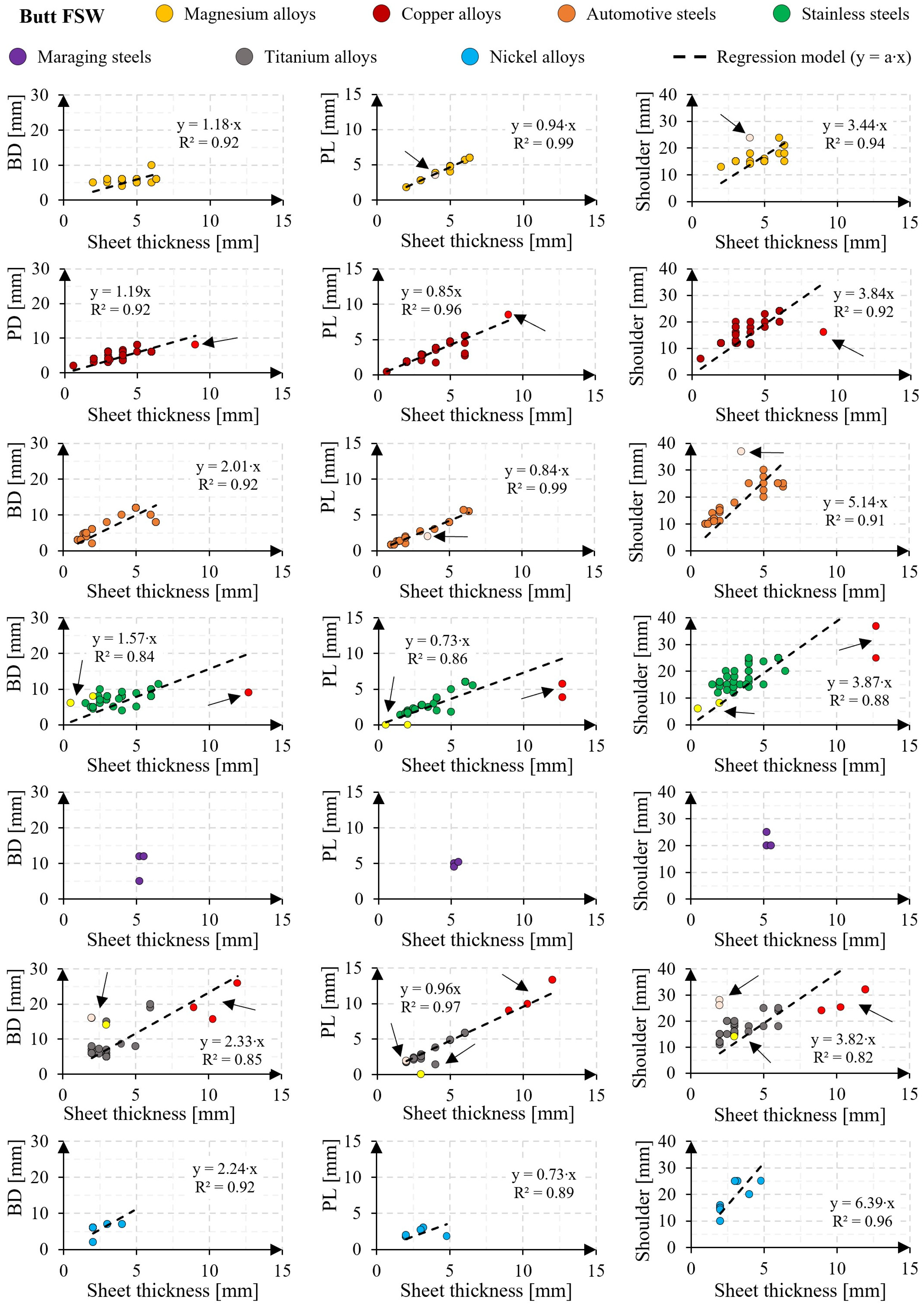
Figure 5 illustrates the relationship between pin base diameter, pin length, and shoulder diameter with sheet thickness (“s”) in the butt FSW of the investigated alloys. Linear regression laws were computed and shown in Figure 5 to provide preliminary guidelines for tool dimensioning during the design phase.
Regression laws were excluded in cases of limited data variability. For the base diameter in butt-joint configurations, the R2 value indicates a greater data dispersion for stainless steels and Ti alloys. In all cases, the regression constant a is larger than 1, meaning that base diameter should exceed the sheet thickness. Notably, values above 2 were observed for automotive steels, Ti, and Ni alloys, reflecting the need for enhanced metal stirring and higher thermal input when welding high-strength and high-melting-point alloys. In contrast, for Mg and Cu alloys, a approaches 1. A similar consideration can be made for the shoulder diameter, which scales proportionally with the sheet thickness, further emphasizing the role of tool design in optimizing FSW performance.
In Figure 5, data points highlighted in red refer to experiments where the shoulder diameter is smaller than that predicted by the regression law. For stainless steels, excluding the red points (AISI 304L, s = 12.70 mm) extracted from [102,103,104], a becomes 1.79, 0.91, and 4.58 for BD, PL, and shoulder diameter, respectively. Similarly, for Ti alloys, removing the red points (Ti6Al4V, s = 9, 10.30, 12 mm) yields a = 2.83, 0.88, and 5.03 [167,173]. For Cu alloys, removing red points (C95800 alloy, s = 9 mm) results in a = 1.23, 0.84, and 4.15 [63]. These findings suggest that for sheet thicknesses exceeding about 7 mm, the linear correlation between dimensions does not hold, as the influence of the shoulder progressively reduces, while the pin becomes more critical [168]. In such a scenario, alternative strategies such as double-sided FSW or the use of a WhorlTM pin design can be considered [2].
Points highlighted in pink in Figure 5 refer to experiments where the shoulder diameter exceeds the regression law predictions. Pink-highlighted data sets include cases for Mg alloys [29] and automotive steels [86], where the shoulder diameters deviate from regression laws with larger-than-predicted values. For Ti alloys [158,159], larger shoulder and pin base diameters were used to enhance heat generation and tool wear resistance. For Mg alloys, after excluding pink points (AM20, s = 4 mm), the regression constants for shoulder diameter become a = 1.16, 0.94, and 3.34 [29]. For automotive steels (HSLA-TRIP joint, s 3.50 mm), the adjusted constants are a = 2.01, 0.85, and 4.95 [86]. For Ti alloys (associated with Ti6Al4V, s 2 mm), the corresponding values become a = 2.25, 0.96, and 3.70 [158,159].
Points highlighted in yellow in Figure 5 refer to experiments where the pin length is smaller than predicted by the regression law. These yellow points often refer to pinless tool configurations (PL = 0), such as joints involving AISI 304 (s = 2 mm) and AISI 316 (s = 2 mm) steels [109], ISI 430M2 (s = 0.5 mm) [115,116], and Ti6Al4V (s = 3 mm) [168]. After excluding yellow points, the regression constants for stainless steels become a = 1.55, 0.73, and 3.86 for BD, PL, and shoulder diameter, respectively. If both yellow and red points are removed, the values for stainless steels adjust to a = 1.77, 0.92, and 4.58. For Ti alloys, removing only yellow points results in a = 2.29, 0.97, and 3.81.

3.2. Tool Features

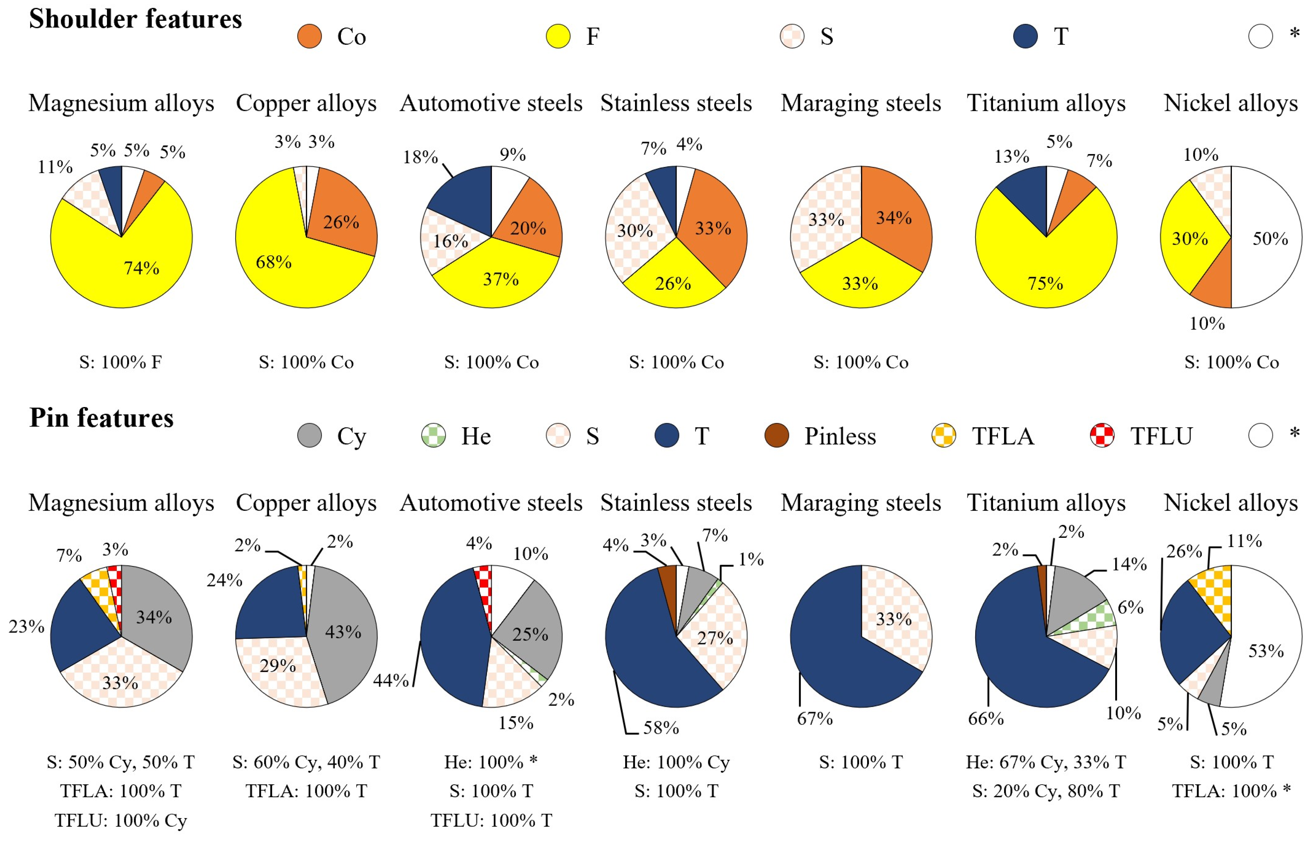
Figure 6 shows the percentage distribution of tool features used for FSW across the investigated alloys. For clarity, the features are categorized into shoulder and pin characteristics, as detailed in the legend. The literature showcases a wide variety of design features, providing insights into common practices and preferences. For shoulder features, secondary characteristics such as a scrolled surface or a spiral pattern (“S”) are often paired with primary features, such as a flat shoulder (“F”) or a convex shoulder (“Co”). The percentages of these combinations are aggregated in Figure 6 for a more comprehensive representation. Similarly, for pin features, secondary features, including hemispherical (“He”), threaded or spiral surfaces (“S”), tri-flate (“TFLA”), and tri-flute designs (“TFLU”), are associated with primary features like cylindrical (“Cy”) and tapered (“T”) pins. This categorization captures the functional versatility of the tools and their adaptability to different alloy requirements.

3.2.1. Shoulder Features

In the earliest stages of FSW development, flat shoulders were widely adopted, due to their simple design. Over time, tapered shoulders emerged as an improvement, effectively trapping the flowing material beneath the shoulder and directing it toward the pin to minimize flash formation. However, the sharp edges of tapered shoulders were prone to excessive wear during the plunge phase [17,175]. Convex shoulders were introduced to provide greater flexibility in the contact area between the shoulder and the workpiece, thus improving joint mismatch tolerance and enabling the welding of parts with varying thicknesses [195]. This design feature is particularly advantageous for applications involving non-uniform parts. However, the convex shoulder initially faced challenges related to the material displacement, as the material tended to flow outward rather than toward the pin center [17]. To address this, convex shoulders are now often paired with a scrolled surface, which promotes centerward material flow and mitigate flash. Secondary features are essential for tool shoulder design. Scrolled surfaces, for instance, promote centerward material flow, particularly in applications with thicker parts [17]. As shown in Figure 6, flat shoulders remain predominant for welding Mg, Cu, and Ti alloys. For example, studies on butt FSW of Mg alloys (s = 3–5 mm) with flat shoulders and cylindrical pins consistently reported defect-free joints, demonstrating the adequacy of simple tool designs for these materials [18,22,28,30]. Scrolled shoulders are less common for Mg alloys, with only two studies [20,24] using threaded or scrolled shoulders. Thakur et al. [24] demonstrated that a scrolled shoulder improved centerward material flow and reduced flash in AZ31B (s = 6 mm) butt joints. For Cu alloys, only one research study [45] investigated butt FSW of commercially pure Cu (s = 5 mm) with a scrolled shoulder. While the high shoulder diameter-to-thickness ratio (4.6) resulted in significant heat input, it reduced hardness in the SZ from 95 HV in the BM to ~80 HV. Microhardness profiles exhibited a W-type shape with a sharp decrease in the HAZ and a slight rise in the SZ, corresponding to grain size variations. The tensile strength of the FSW joints was significantly lower than the BM, mainly due to the loss of cold-work hardening caused by recrystallization in the HAZ. Yield stress dropped by over 60%, while ultimate stress decreased by about 15%. For steels, flat shoulders are less common than convex designs, which improve metal stirring in these high-strength materials. Flat shoulders were used in 16, 18, and 2 studies on automotive steels, stainless steels, and maraging steels, respectively. Convex shoulders combined with scrolled surfaces predominate, accounting for 80% of convex shoulders in automotive steels, 88% in stainless steels, and 100% in maraging steels. These designs are often combined with wear-resistant PCBN tools, reflecting their advantages in handling high-strength alloys. In Ti alloys, flat shoulders are mostly used (30 occurrences, up to 75%) because the chemical affinity between Ti and PCBN promotes rapid tool wear, making scrolled surfaces impractical [141]. Alternative materials, such as WRe, WLa, and WC, also lack the wear resistance required for widespread adoption of complex tool features [164,173,196], leading to the absence of scrolled shoulders in the reviewed studies on Ti alloys. For Ni alloys, shoulder features are often unspecified (up to 10 occurrences). When declared, scrolled and convex shoulders are exclusively associated with PCBN tools, highlighting their compatibility with high-performance applications.

3.2.2. Pin Features

Figure 6 showcases a wide variety of pin designs used in FSW. Contrarily to cylindrical pins, truncated cone pins provide better control of heat flow along the thickness direction and generate high hydrostatic pressure in the SZ, enhancing material stirring and nugget integrity [197]. The use of tapered pins increases from Mg and Cu alloys (7 and 12 occurrences, respectively) to automotive steels, stainless steels, maraging steels, and Ti and Ni alloys (21, 40, 4, 32, and 5 occurrences, respectively). Threaded surfaces in pin designs boost the ratio between the dynamic volume and static volume of the weld, reducing void formation [195]. Pinless tools are suitable for thin sheets (s < 3 mm), where the pin influence reduces progressively [168]. Innovative pin designs developed by TWI, such as WhorlTM, MX-TrifluteTM, and MX-TriflatTM [2], have also been investigated. The WhorlTM design features a scoop-shaped shoulder with a tapered pin and a helical ridge with side flats to guide plasticized material downward. To optimize material flow, the spacing between ridges should exceed the ridge thickness [195]. This design is particularly effective for butt FSW of thick components (s up to 75 mm) in double-sided FSW applications [2]. The MX-TrifluteTM design offers a higher dynamic-to-static volume ratio (e.g., 2.6:1 compared to 1:1 for conventional and 1.8:1 for WhorlTM tools when welding 25 mm thick plates) [2]. It can double the welding speed and reduce vertical force requirement by 20% [195]. However, this design is unsuitable for welding high-strength alloys, due to its high wear rate. The MX-TriflatTM design enhances heat generation by plastic deformation, resulting in finer grain structures in the weld compared to conventional cylindrical pins. However, its sharp-shape profile suffers often from stress concentration, tool fracture during the initial plunge stage, and higher wear rate [197]. The WhorlTM design was not found in the reviewed literature, but applications of MX-TrifluteTM and MX-TriflatTM designs were found in [27,82,83] and [20,23,63,181,192], respectively. These advanced pin designs demonstrate specific advantages and limitations, indicating their suitability for tailored applications rather than general-purpose use.

3.3. Tool Materials

Figure 7 shows the percentage distribution of tool materials used for FSW across the investigated alloys.
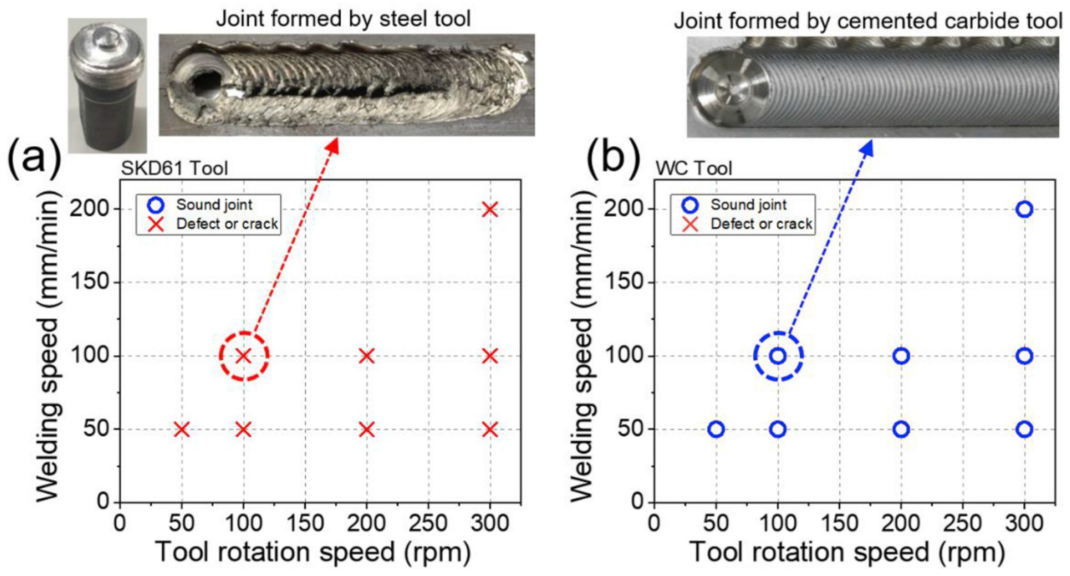
A wide range of tool materials has been evaluated in the literature. For Mg alloys, tool steels, such as AISI H13 and high-speed steels (HSSs), are the most commonly used materials, generally exhibiting low wear rates for the tool. Thakur et al. [24] enhanced the wear resistance of an H13 tool by quenching and tempering heat treatment, reaching a hardness of 52 HRC. Zhou et al. [28] pointed out that tool material selection requires consideration of not only wear resistance, but also thermal and surface-wettability properties, as these notably affect joint quality, even under fixed process parameters. For instance, Figure 8 demonstrates that a WC tool outperforms an SKD61 tool for butt FSW of LZ91 alloy (s = 3 mm). For Cu alloys, WC tools account for 36% of applications, while steel tools represent 46%. Pashazadeh et al. [46] proposed using WC for the pin and HSS for the shoulder, to reduce tool cost. In the case of harder alloys like automotive steels, a broader variety of tool materials is employed. WC tools are used in 55% of studies because of their cost-effectiveness, while advanced materials such as WRe, PCBN, and their composites are mainly reserved for welding high-strength automotive steels [90,91,92,93,94,95]. Shaysultanov et al. [84] observed black pores in the microstructure of butt joints in TRIP sheets, attributed to WC tool wear and the formation of brittle white bands [179]. Similarly, Mahmoudiniya et al. [75] noticed wear-related issues in the butt FSW of DP700 (s = 2 mm) at a rotational speed of 600 rpm. These issues, absent at higher speeds (800 and 1000 rpm), resulted in reduced elongation at fracture (4.7% at 600 rpm vs. 10.7% and 9.2% at 800 and 1000 rpm, respectively), highlighting the impact of tool wear on joint performance. Figure 9 shows a WC particle (maximum size ~14 μm) detected in the SZ during butt FSW of DP700 (s = 2 mm, ω = 600 rpm, v = 50 mm/min), along with the corresponding EDS analysis [75].
Ragu Nathan et al. [81] recommended using higher heat input during the FSW of HSLA steels with W-based tools to soften the materials, improve plasticized-material flow around the tool pin, and minimize tool pin wear. However, WC tools have temperature limitations, as their hardness decreases notably from about 1600 HV up to 600 °C to about 1300 HV at 1100 °C [100]. Furthermore, at temperatures exceeding 850 °C, elements such as Co, Fe, Mo, and Cr can dissolve from WC, leading to the formation of brittle carbides (e.g., M3C, M6C, and M23C6). These carbides are susceptible to removal by the mechanical action of the tool, potentially causing craters and voids on the tool surface [100]. The use of WRe, PCBN, and their composite tools is more prevalent for stainless steels, accounting for 62% of applications compared to 34% for automotive steels. WRe tools are preferred for their ductility, as the addition of Re lowers the ductile-to-brittle transition temperature of pure W to below room temperature, improving fracture resistance [198]. Despite this advantage, WRe tools are prone to high wear rates, resulting in shorter lifespan and increased costs [82]. Typical WRe compositions contain either 5 or 25 wt.% of Re. PCBN tools, known for their excellent wear and temperature resistance, also find significant application in FSW. However, their limited ductility makes them susceptible to pin failure under high traverse loads. This restricts their use to scenarios with thinner sheets and slower welding speeds [82,92]. To address these limitations, variants of PCBN tools with different binder compositions have been developed. For example, WRe matrices (or binders) enriched with PCBN particles aim to combine the benefits of both materials, while mitigating their individual weaknesses. A comparative analysis of wear rates for PCBN and WRe (25 wt.%) tools has been performed during the butt FSW of HSLA-65 steel (s = 6.35 mm) [82,83].
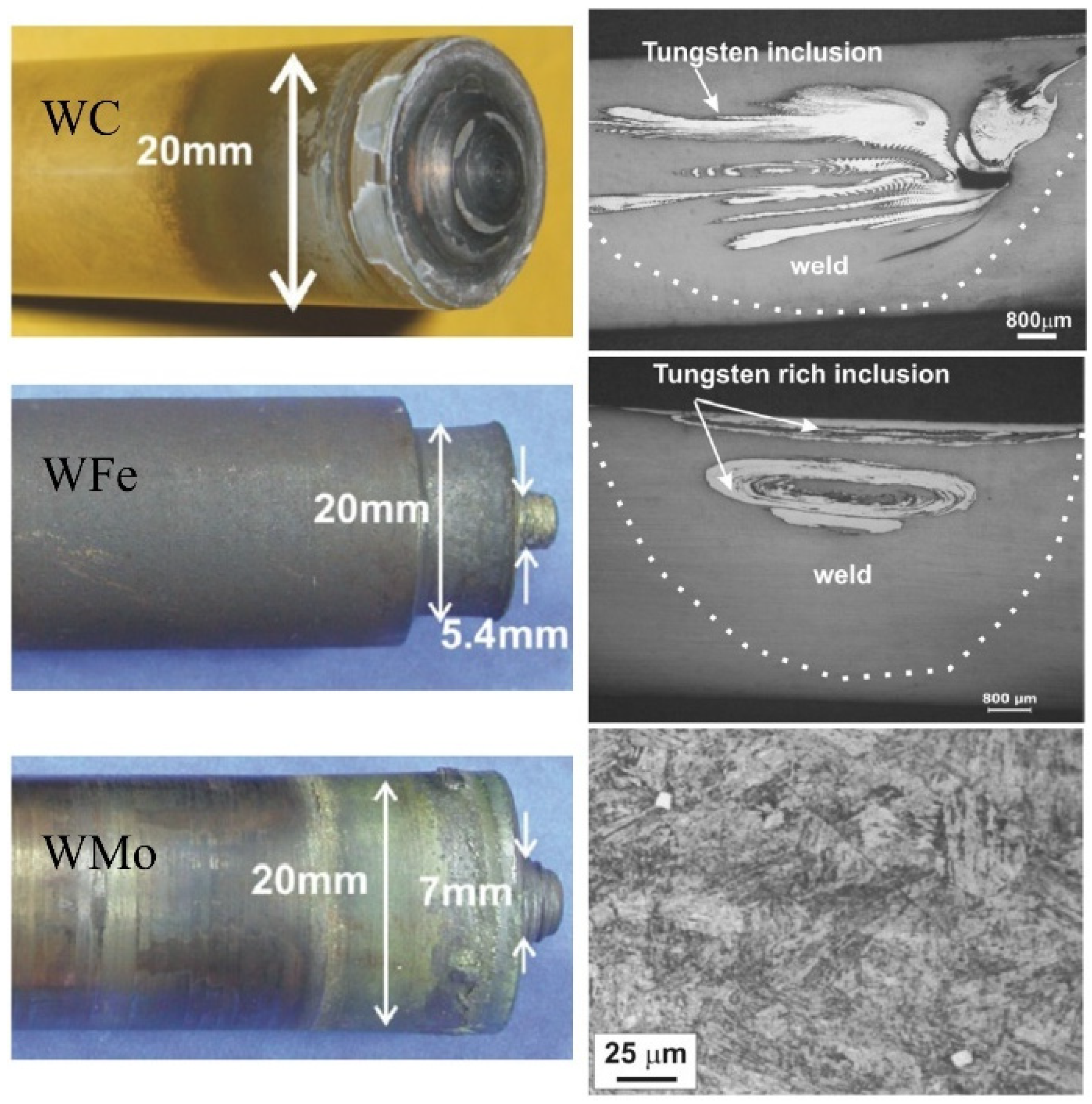
Under similar welding conditions, PCBN tools operate at lower temperatures than WRe tools. This difference is attributed to the lower thermal conductivity and higher friction coefficient of PCBN. X-ray tomography has revealed that WRe tools tend to release debris primarily on the RS of the weld, near the tool tip. This debris is more prevalent at slower welding speeds, suggesting that temperature has a greater influence on WRe tool wear than vertical force. Li et al. [111] observed an increase in band structures formed on the AS of the SZ when the rotational speed increased from 300 to 400 rpm during the butt FSW of austenitic S32654 steel (s = 2.4 mm). These bands were attributed to particles worn from the WRe tool, as displayed in Figure 10. For maraging steels, Meshram et al. [137,139] compared the performance of different tool materials, including pure W, WC, WFe, WMo, and PCBN, in butt FSW of MDN-250 (s = 5.2 mm). Figure 11 shows the post-welding appearance of the tool and the corresponding joint cross-section. The pure-W tool fractured completely during the plunging phase, due to extreme brittleness, a result of its high ductile-to-brittle transition temperature. The WC tool exhibited significant wear, with the pin completely worn away after a weld length of 200 mm. WFe tools demonstrated reduced wear compared to other materials; however, softening of the tool shoulder at elevated temperatures caused noticeable bulging. Welds made with WMo and PCBN tools showed the best results. Notably, welds produced using WMo tools did not exhibit W inclusions under optical microscopy. Although PCBN tools provided excellent performance, their high cost makes WMo tools a more cost-effective and durable alternative for welding maraging steel. For Ti alloys, a wide variety of tool materials has been tested. Wu et al. [199] noted that although PCBN tools perform well with steels, they experienced severe wear when used with Ti alloys. High-temperature chemical reactions between the tool and workpiece can result in the formation of α Ti(N) and Ti borides, originating from the dissolution of B, O, or N from PCBN debris into Ti [141,200]. TEM images reported by Wu et al. [199] revealed such contamination in Ti6Al4V alloys processed via friction stir processing (FSP) with PCBN tools. WRe alloys are characterized by their ability to withstand high operating temperatures and, hence, are well-suited for joining Ti alloys. However, their high production cost remains a challenge [201].
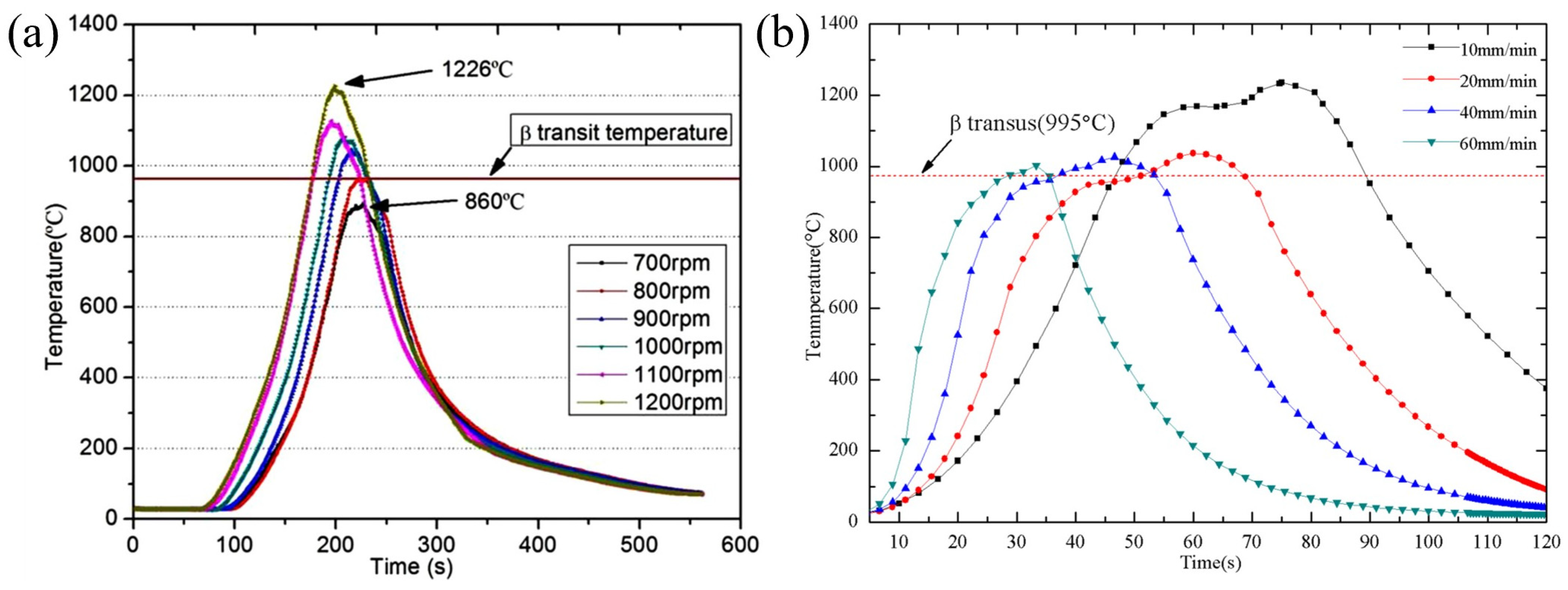
Ji et al. [155,161] investigated the use of a heating system beneath the butt joint of Ti6Al4V (s = 2–2.5 mm) to reduce the wear rate of WRe tools. This heating system increased peak temperatures to 1134 °C (compared to 1048 °C in conventional FSW) and minimized temperature gradients along the joint. EDS analysis revealed a lower concentration of W and Re elements in the SZ top region, indicating reduced tool wear. Ma et al. [196] found that in the butt FSW of Ti6Al4V (s = 2 mm), fatigue crack mainly initiated in the SZ rather than in regions with lower hardness. This was attributed to the WRe contamination caused by tool wear, as shown in Figure 12. WRe alloys also outperform WC tools in terms of wear resistance. For instance, Buffa et al. [164] reported that switching from a WC (K10) tool to a WRe (25 wt.%) tool during butt FSW of Ti6Al4V (s = 3 mm) increased tool life from 5 to about 30 m. Mironov et al. [201] reviewed the wear mechanism of WC tools in the FSW of Ti alloys. The strong chemical affinity between Ti and C at high temperatures can lead to the diffusion of C into Ti, forming an adhesion layer that alters friction conditions and heat input [202]. Other studies suggested that WC tool wear may result from the oxidation of the WC phase at high temperatures. This oxidation, accompanied by volume expansion, can induce cracking and accelerate tool degradation [203].
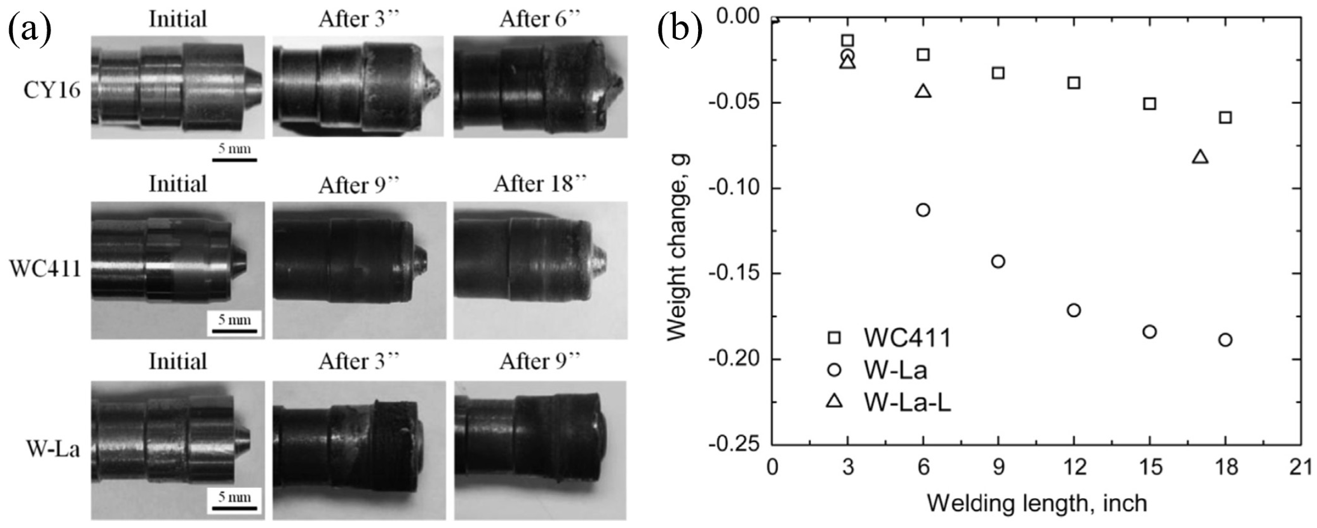
Li et al. [204] identified WLa tools as a cost-effective alternative with an optimal balance between high-temperature strength and durability. These alloys typically contain 1 wt.% La2O3 in their composition. Edwards et al. [205] used a WLa tool in the butt FSW of Ti6Al4V (s = 5 mm), observing that rotational speeds below 300 rpm and welding speeds below 75 mm/min produced a fine-grained microstructure. However, these parameters also led to high process loads and significant tool wear. Pilchak et al. [173] reported the presence of the β phase in the SZ of Ti6Al4V butt joints (s = 6 mm), attributing it to the diffusion of W—a β phase stabilizing element –from the WLa tool at high temperatures. Wang et al. [202] compared the performance of WC-Co and W—1.1% La2O3 tools during the butt FSW of Ti6Al4V (s = 2 mm). Two different compositions for the WC-Co-based tool were tested: CY16 (73% WC, 8% Co, 8% TiC, and 11% TaC) and WC411 (89% WC and 11% Co). The CY16 tool exhibited severe fracture failure and was excluded from further analysis. The W—1.1% La2O3 tool suffered from significant plastic deformation during the welding process, as shown in Figure 13a. To mitigate this issue, the authors proposed a revised tool geometry, designed as “WLa-L” in Figure 13b, featuring a cylindrical pin with a larger pin tip diameter (6.3 mm vs. 2.5 mm in the original design). Performance evaluations indicated that the WC411 tool performed comparably to the WLa-L tool (Figure 13b).
Figure 12. Butt FSW of 2 mm thick Ti6Al4V. (a) Cross-section [206] and (b) EDS analysis (ω 120 rpm, v 30 mm/min) [196].
Jmmp 09 00036 g012
Amirov et al. [150] and Tarasov et al. [162] used a Ni superalloy (ZhS6U) to perform butt FSW on Ti1.5Al1Mn and Ti6Al4V alloys, respectively (s = 2.5 mm in both studies). Amirov et al. successfully joined over 500 mm of Ti1.5Al1Mn with minimal tool wear, demonstrating that the ZhS6U alloy is well-suited for the FSW of Ti α’ alloys. Tarasov et al. [162] further improved tool performance by incorporating a cooling system, which reduced pin wear over approximately 2 m of Ti6Al4V, Figure 14. Du et al. [148] investigated the butt FSW of Ti4Al0.005B (s = 5 mm) using a tool made of a Co alloy. They identified a contaminated zone in SZ, which expanded as welding speed decreased, due to the longer welding time and temperature. The pattern and location of the contaminants suggest that diffusion wear was the predominant erosion mechanism, as mechanical exfoliation would have resulted in smaller, more dispersed contamination. For Ni alloys, 77% of tools used in FSW are made of WC. Numerous studies have reported the presence of WC particles in the weld, due to tool wear [179,183,184,186,188,193].
Song et al. [184] noticed a distinct band structure in the SZ cross-section of an Inconel 625 joint (s = 2 mm) obtained via butt FSW. EDS spectral analysis revealed a higher W concentration in this region compared to the unaffected areas of the SZ, as illustrated in Figure 15. Saha et al. [191] performed induction-assisted butt FSW of Inconel 718 (s = 3 mm) using a WC tool. By maintaining a controlled temperature range of 740–760 °C (vs. 670–720 °C in conventional FSW), they reduced the thermal gradient across the sheet thickness. This approach significantly reduced tool wear, attributed to a reduction in vertical force during welding, from about 40 kN to about 20 kN. Similarly, Raj et al. [189] used induction-assisted butt FSW to join Inconel 718 (s = 3 mm) with a WC tool. This method resulted in a 26% reduction in vertical force, attributed to material softening, which extended tool life. Sengupta et al. [182] performed electrically assisted butt FSW of Inconel 601 (s = 2 mm) using a WC tool, finding a wear rate of 0.13–0.25%, comparable to the 0.14–0.26% observed in conventional FSW. Sato et al. [181] reported the presence of PCBN debris during the butt FSW of Inconel 600 (s = 4.8 mm).
Hanke et al. [185] investigated the wear mechanism of tools with a WRe matrix (or binder) reinforced with PCBN during the butt FSW of Inconel 625 (s = 3.2 mm). The main wear mechanism included the detachment of BN grains due to the thermal softening of the metallic binder phase and the dissolution of BN into the hot material within the SZ. These phenomena ultimately led to pin fractures. Reducing the rotational speed proved effective in lowering the welding temperature, minimizing tool wear, and producing a more homogeneous SZ.

3.4. Process Windows

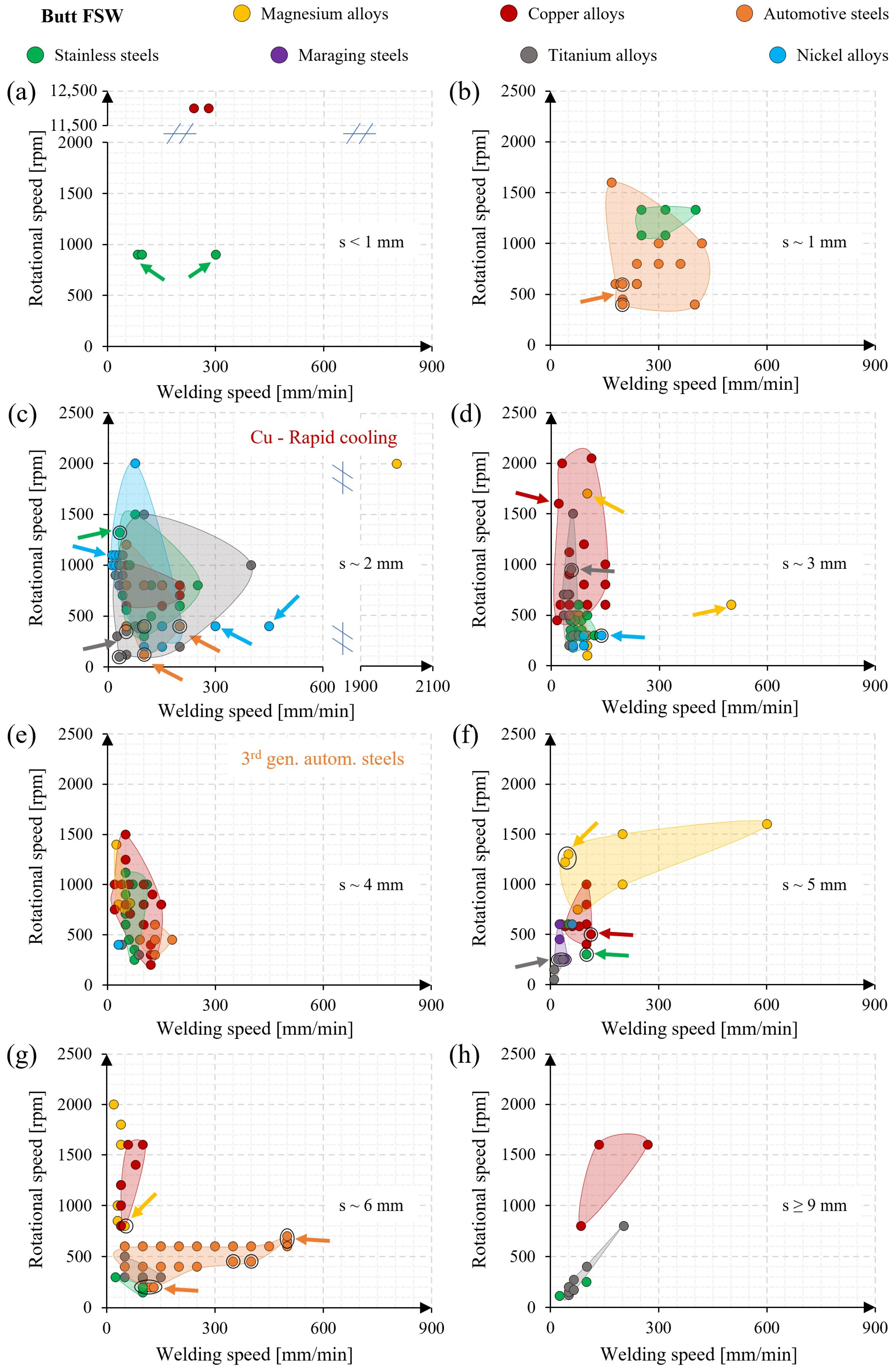
Figure 16 illustrates the process windows for the investigated alloys in a butt-joint configuration. For clarity, the data are grouped according to sheet thickness. The data include only the combinations of rotational and welding speeds that produced sound joints. When multiple sound joints were obtained with different parameter sets, priority was given to those producing the highest tensile strength, if such data were available. If tensile strength data were not reported, all successful parameter combinations were included. Where multiple data points were available, Figure 16 illustrates the potential welding window for the investigated alloys. Typically, the plunge depth remains consistent across the reviewed studies, relative to sheet thickness. Moreover, Figure 5 reveals correlations among base diameter, pin length, shoulder diameter, and sheet thickness, allowing these parameters to be excluded from the analysis. As a result, the focus in Figure 16 is placed exclusively on process parameters such as welding and rotational speeds.

3.4.1. Butt FSW of Magnesium Alloys

High-productivity process parameters (2000 rpm, 2000 mm/min) were selected to weld AZ31 (s = 2 mm) [20], resulting in a smooth hardness transition from the BM to the SZ, and achieving a tensile strength of 225 MPa compared to 250 MPa for the BM. Mengran et al. [18] used rapid cooling using liquid CO2 during the FSW of commercially pure Mg (s = 3 mm) at 1700 rpm and 100 mm/min (indicated by a yellow arrow in Figure 16d). This method maintained the material in a quasi-static and deformed state, reducing the SZ grain size from 33.6 to 9.1 μm. Zhou et al. [26] strongly improved the productivity of AZ61 and AZX612 joints (s = 3 mm) by introducing a second tool without a pin on the lower surface of the joint, operating at rotational speeds between 400 and 600 rpm (indicated by a yellow arrow in Figure 16d). This approach increased the welding speed to 500 mm/min.
For LZ91 (s = 3 mm), the process window (Figure 8) showed optimal results at a welding speed of 100 mm/min [28]. Wang et al. [22] investigated the low-cycle fatigue behavior of AZ31 joints (s = 4 mm), testing two rotational speeds—750 rpm and 1500 rpm—at a fixed welding speed of 47.5 mm/min. Joints realized at the lower rotational speed exhibited a fine-grained structure, leading to significantly higher stress amplitudes than those welded at 1500 rpm. For AZ31B with s of ~5 mm, thermal input was modified using electrically assisted FSW [23], while heat dissipation in ZE41 joints was controlled via underwater FSW [30] (refer to points marked with a black circle and a yellow arrow in Figure 16f). In the electrically assisted FSW, tensile strength reached 210 MPa (248 MPa for the BM) at 1300 rpm, 50 mm/min, and a current of 200 A. This approach reduced the weakly welded area at the SZ bottom from about 300 to 130 μm (Figure 17) and eliminated the boundary line between the SZ and TMAZ on the AS. In the underwater FSW, increased heat dissipation limited grain growth near the SZ (from about 40 to 25 μm), achieving a tensile strength of 189 MPa (168 MPa under conventional air conditions) and shifting fracture location from the SZ to the BM (ω = 1220 rpm, v = 40 mm/min). Thakur et al. [24] conducted double-sided FSW of AZ31B (s = 6 mm) at 800 rpm and 50 mm/min (indicated by a black circle and a yellow arrow in Figure 16g), testing tilt angles of 0° and 2°. The 2° tilt angle improved material flow by enhancing downward and lateral frictional forces on the rear side of the tool shoulder, filling cavities observed with the 0° tilt. This configuration achieved a tensile strength of 210 MPa compared to 180 MPa for the 0° tilt angle. Saini et al. [25] tested two welding speeds (20 mm/min and 40 mm/min) with three rotational speeds (1600–2000 rpm). The joint with the highest specific thermal contribution (STC) (100 rpm/mm/min), achieved at 2000 rpm and 20 mm/min, exhibited the highest tensile strength of 275 MPa, compared to about 310 MPa for the BM.

3.4.2. Butt FSW of Copper Alloys

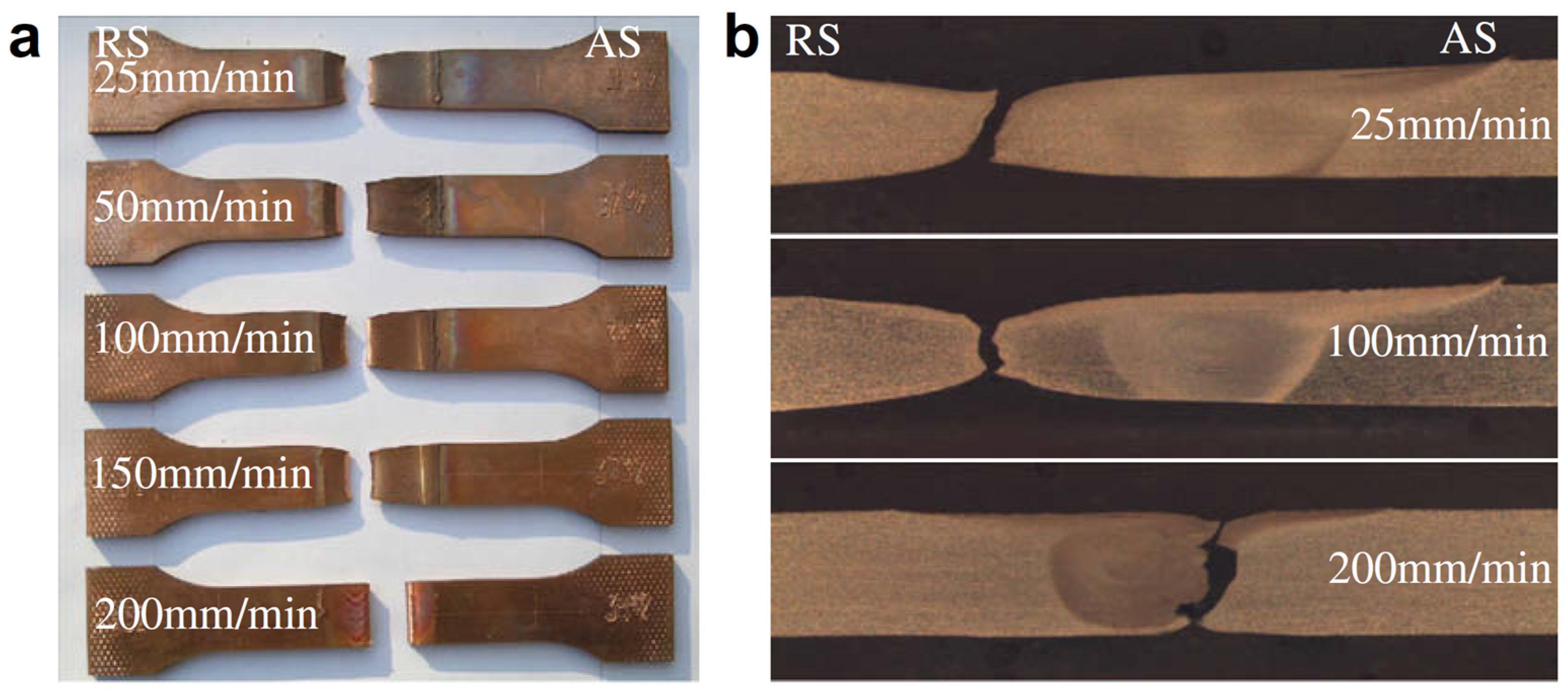
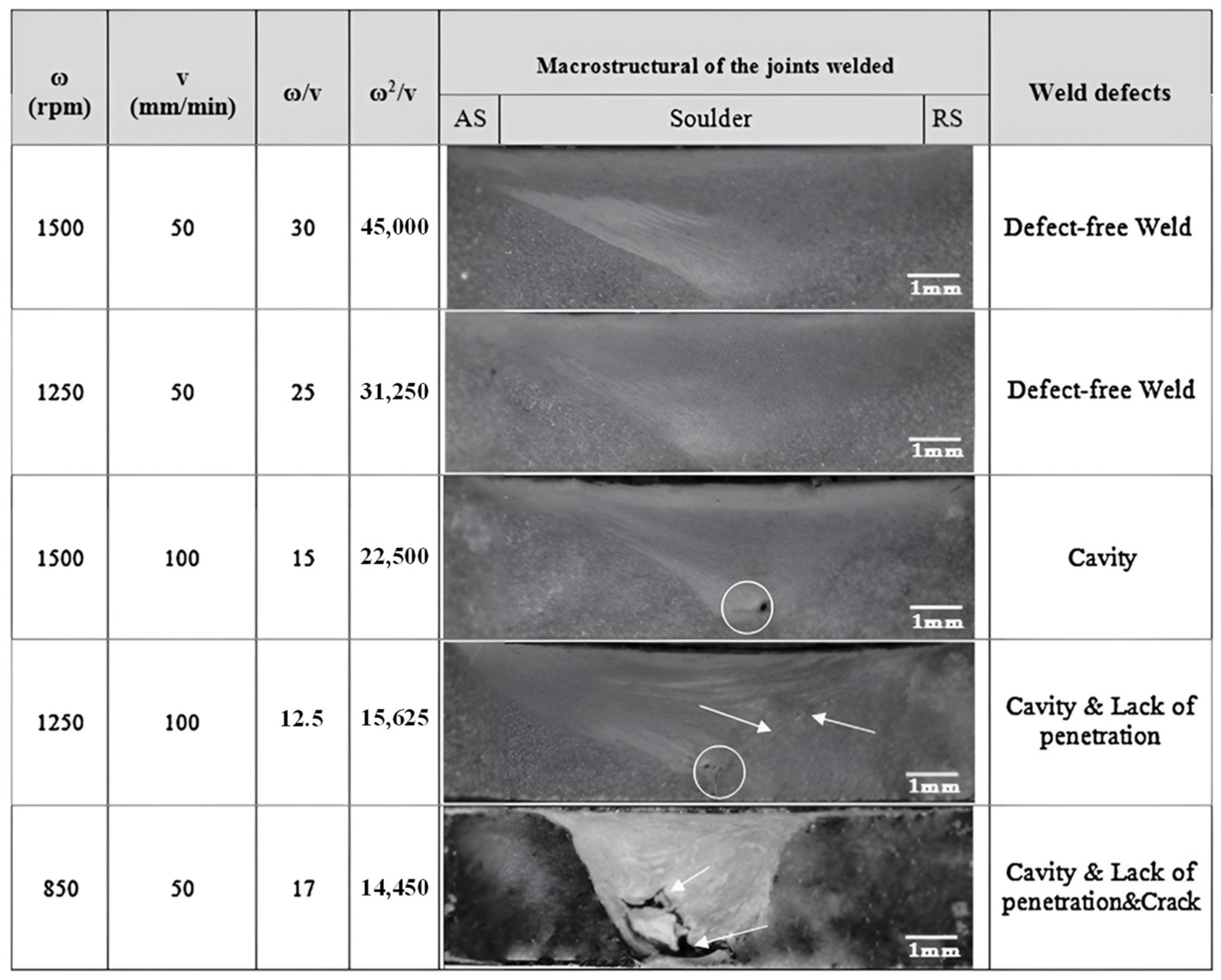
Very high rotational speeds in the range of 10,000–14,000 rpm were tested for welding commercially pure Cu (s = 6 mm) and brass Cu-37Zn (s = 6 mm) [64], with welding speeds ranging from 160 to 320 mm/min. At low STC, minimal interpenetration of the metals resulted in unwelded regions near the bottom of the weld. Conversely, excessively high STC caused elevated temperatures, limiting the intermixing required for a strong metallurgical bond. For thinner Cu alloys (s ~2 mm), Xu et al. [35,36,47,49,50,51,57] carried out extensive studies on commercially pure Cu and brass alloys, using rotational speeds in the range of 600–800 rpm and welding speeds of 150–200 mm/min. They employed a rapid cooling system using liquid N2 or CO2 sprayed on the weld surface to freeze the microstructure and mitigate post-annealing effects. This technique reduced the grain size within the SZ to about 2 μm (vs. about 20 μm for conventional FSW) [36]. This method also expanded the process window, enabling welding speeds up to 200 mm/min, whereas Heidarzadeh et al. [53] reported a limit of 50 mm/min. Meran et al. [52] investigated the welding of brass Cu-30Zn (s = 3 mm) at a rotational speed of 2050 rpm and welding speeds in the range of 20–140 mm/min. At 112 mm/min, the joint exhibited fracture in the BM and achieved a tensile strength comparable to the BM (about 350 MPa). Other studies on commercially pure Cu (s ~3 mm) explored rotational speeds in the range of 600–2000 rpm and welding speed of 20–150 mm/min [37,38,39,41]. Yaghoubi et al. [39] used a water cooling system under the welded joint, reducing the grain size to 2 μm in the SZ and 47 μm in the HAZ (vs. 18 μm and 150 μm in conventional FSW, respectively). This reduction was achieved by lowering the peak temperature from 600 to 250 °C at a rotation speed of 1600 rpm (refer to the red arrow in Figure 16d). Shen et al. [37] found that welding speed had a minimal effect on tensile strength in the range of 25–150 mm/min at 600 rpm, but tensile strength decreased noticeably beyond 200 mm/min (from about 270 to 255 MPa). This also shifted the fracture location from the RS (in the TMAZ-HAZ-BM area) to the AS (at the interface between the SZ and TMAZ), as shown in Figure 18. Rizi et al. [60] investigated the welding of Al bronze Cu alloy (C95300, s = 4 mm) using rotational speeds in the range 850–1500 rpm and welding speeds of 50 mm/min and 100 mm/min. Figure 19 shows the cross-section of joints welded at different ω/v (proportional to heat input) and ω2/v ratios (proportional to peak welding temperature). Their findings revealed that ω2/v had a greater influence on defect volume than ω/v. Defects were detected at ω2/v values below 30,000 rpm2/mm/min, with defect formation intensifying at lower ratios (from 22,500 to 14,450). Increasing this ratio to 30,000 yielded defect-free welds.
Zhou et al. [58,59] investigated the FSW of CuSn6 alloy, varying rotational speed between 400 and 1000 rpm (at a fixed welding speed of 100 mm/min) and welding speed between 50 and 150 mm/min (at a fixed rotational speed of 800 rpm). Joints welded at 1000 rpm with welding speeds different from 100 mm/min exhibited slightly lower tensile strength than the BM (about 380 MPa vs. 410 MPa). Notably, only the joint welded at 400 rpm showed a groove-like defect, while all other process-parameter sets produced tensile strengths comparable to the BM. Xie et al. [55] studied the FSW of brass Cu-38Zn joints (s = 5 mm) at a fixed welding speed of 100 mm/min and rotational speeds in the range of 400–1000 rpm. The results showed no significant changes in tensile strength, which remained consistent with the BM (400 MPa). However, increased rotational speed enhanced elongation at fracture (from 37 to 44%). This improvement was attributed to a size reduction of non-recrystallized grains and an enlargement of recrystallized grains. Alavi Nia et al. [44] performed FSW on commercially pure Cu (s = 5 mm) using a cooling system positioned beneath the joint (refer to the black circle and the red arrow in Figure 16f). Similarly, Selvaraju et al. [61] performed FSW on Ni-Al bronze NAB C95800 (s = 6 mm), testing three welding speeds (60, 80, and 100 mm/min) and three rotational speeds (1200, 1400, 1600 rpm). Tunnel defects were observed at the joint root for most process-parameter combinations. However, two specific conditions produced sound joints: (i) 1600 rpm and 60 mm/min, and (ii) 1400 rpm and 80 mm/min. Siva et al. [62] also investigated the FSW of NAB C95800 (s = 6 mm) at 1600 rpm and 100 mm/min. They compared conventional FSW with thermite heat-assisted FSW, which used a thermite reaction of Al-CuO powder spread on the top joint surface. Conventionally welded joints achieved a tensile strength of 550 MPa (compared to 480 MPa for the BM). In contrast, thermite heat-assisted FSW showed a tensile strength of 600 MPa. The higher heat input in the thermite-assisted method enhanced material flow along the sheet thickness, effectively eliminating tunnel defects and improving joint quality.

3.4.3. Butt FSW of Automotive Steels

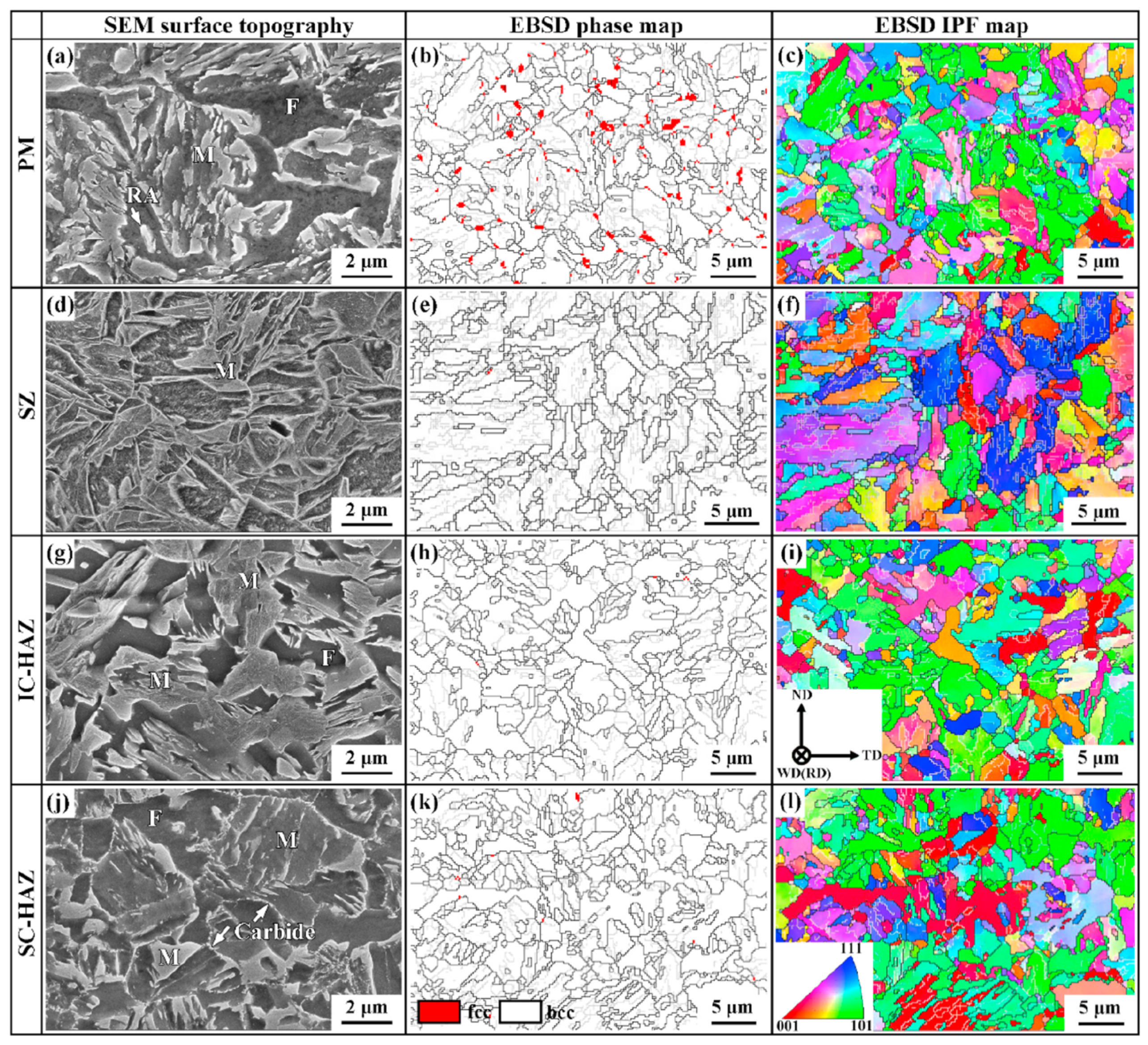
The processability region for automotive steels with a thickness of approximately 1 mm is shown in Figure 16b. Black circles refer to joints of third-generation automotive steels [94,95], while the other data pertain to first-generation alloys. Wang et al. [95] studied the welding of Q&P 1180 steel (s = 1.6 mm) using a rotational speed of 450 rpm and a welding speed of 200 mm/min. Figure 20 shows SEM images of the typical zones of the joint: BM (parent metal—PM), SZ, inter-critical HAZ (IC-HAZ experienced a maximum temperature in the A3–A1 range), and sub-critical HAZ (SC-HAZ experienced a maximum temperature below A1). The BM exhibited ultra-fine structures, including ferrite (F), retained austenite (RA, Figure 20b), and martensite (M), without preferential texture (Figure 20c) or carbide precipitates, due to the suppressive effect of alloying elements such as Si and Al. The SZ consisted solely of martensite, Figure 20d, confirmed by the EBSD phase map, Figure 20e, which shows no significant grain size variation. The IC-HAZ contained an ultra-fine dual phase structure with irregularly shaped ferrite and martensite (Figure 20g), with an increased volume fraction of ferrite compared to the BM. In the SC-HAZ, the volume fraction and grain size of the austenite (A) remained unchanged (Figure 20j–l). Carbides precipitated along grain boundaries, accompanied by the tempering of pre-existing M (Figure 20j).
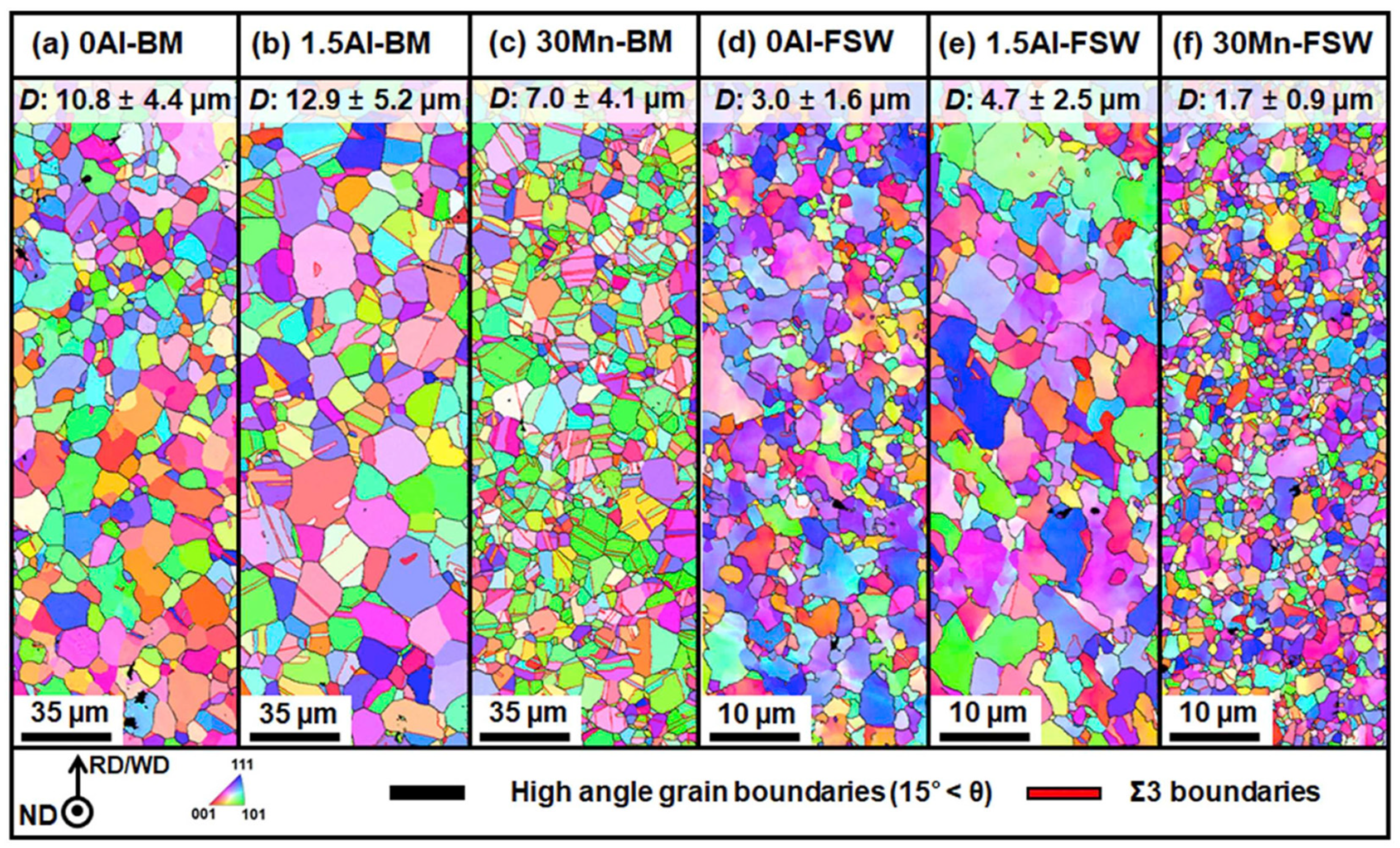
A rotational speed of 600 rpm and welding speed of 240 mm/min were successfully employed to weld low-carbon high-strength steels (s = 1–1.2 mm) with tensile strengths from 590 to 1500 MPa [71,78]. Kim et al. [72] reported defect-free welds for DP590 steel (s = 1.4 mm) across a range of 600–1000 rpm and 120–420 mm/min. Optimal results were obtained with a specific STC between 2.2 and 3.3 rpm/mm/min. Values below 2.0 rpm/mm/min caused groove-like defects, while higher values (>4.4 rpm/mm/min) produced rough weld surfaces due to excessive heat input. Studies on IF, S12C, and S35C steels (s = 1.6 mm) evaluated the effect of welding speeds of 100–400 mm/min at a fixed rotational speed of 400 rpm [68,69,70]. IF steel joints exhibited consistent tensile strength (about 300 MPa) with a reduction in SZ grain size (5–6 μm vs. 24 μm in the BM). In contrast, S12C joints exhibited an increased tensile strength with welding speed, peaking at 490 MPa at 400 mm/min. S35C joints reached the highest tensile strength, about 790 MPa, at 200 mm/min. These variations were attributed to the relationship between peak temperature and A1 or A3 critical points: FSW refined the ferrite–austenite microstructure, enhancing joint strength. For automotive steels with a thickness of about 2 mm, black circles and orange arrows in Figure 16c refer to second-generation alloys [87,88,89,207]. For TWIP steel joints, a fixed rotational speed of 400 rpm and increasing welding speeds 50–200 mm/min) raised tensile strength from 1709 to 2066 MPa, driven by grain boundary strengthening from grain refinement and increased dislocations [89]. Lee et al. [88] investigated the FSW of different TWIP steels, including Fe-18Mn-0.6C, Fe-18Mn-0.6C-1.5Al, and Fe-30Mn-3Al-3Si. IPF maps of Figure 21 show finer grains in Fe-30Mn-3Al-3Si, likely due to solute-drag pinning from alloying elements.
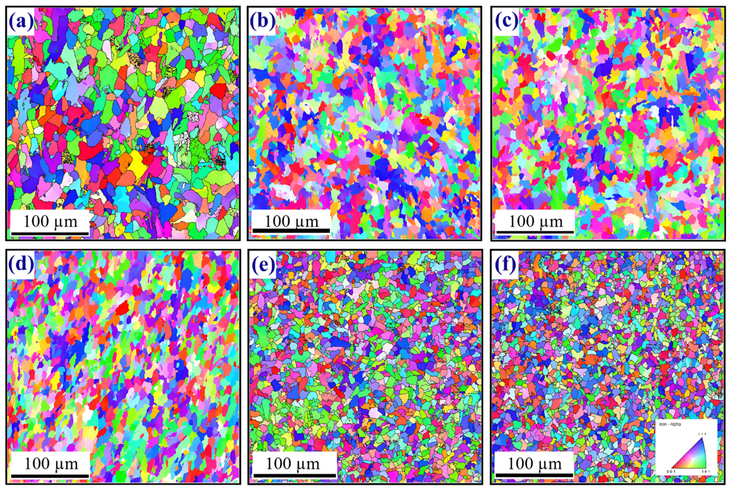
Additional investigations on DP700 steel (s = 2 mm) are detailed in [75,76,77]. With an optimal rotational speed of 800 rpm and welding speeds ranging from 50 to 150 mm/min, the tensile strength of the welds increased from 662 to 687 MPa as the welding speed increased (vs. 723 MPa for the BM). Thermocouples placed at the bottom surface of the SZ measured a temperature close to the A1 critical point when the welding speed was 200 mm/min, which resulted in noticeable lack of material mixing. A press-hardening steel (PHS) (s = 2 mm) was welded with a high STC of 20 rpm/mm/min and 30 rpm/mm/min [85]. In both cases, the hardness of the SZ significantly exceeded that of the BM (325–375 HV vs. 150 HV), and the tensile strength reached about 700 MPa. Shaysultanov et al. [84] investigated the effect of rotational speed (400–1000 rpm range at 100 mm/min) for TRIP steel (s = 2 mm). Tunnel defects were detected from 600 rpm, particularly near the pin tip at the AS. The maximum tensile strength (879 MPa vs. 870 MPa for the BM) was reached by reducing the welding speed to 50 mm/min at 400 rpm. Ramesh et al. [79] performed the FSW of HSLA steel (s = 3 mm), investigating the influence of welding speed (57–97 mm/min at 500 rpm). As shown in the EBSD maps in Figure 22, an increase in welding speed resulted in reduced grain size in the SZ, from 9.7 to 6.3 μm. The maximum tensile strength (553 MPa) and hardness (about 220 HV) were achieved at 77 mm/min. However, beyond 87 mm/min, both properties decreased, due to insufficient upper bainite formation and the predominance of fine ferrite. This indicates that the peak temperature did not significantly exceed the A3 critical point.
For sheet thicknesses around 4 mm, the data in Figure 16e exclusively pertain to DH36 automotive steel joints [90]. In all cases, the upper surface of the welds was defect-free. The optimal surface finish was achieved under the following conditions: 300 rpm and 132 mm/min, and 450 rpm and 180 mm/min. Welding temperatures ranged from a minimum of 750 °C (300 rpm and 132 mm/min) to a maximum of 1125 °C (600 rpm and 132 mm/min). Barnes et al. [82] carried out FSW on HSLA steel (s = 6.25 mm) using two different tool materials. Sound joints were successfully obtained with a PCBN tool at 400 rpm and 50–250 mm/min, and with a WRe tool at 600 rpm and 50–250 mm/min. Focusing on third-generation steels [91,92,93], DH36 (s = 6 mm) was welded at 160–700 rpm and 100–500 mm/min. All tested conditions produced defect-free welds, with the highest performances marked with a black circle and orange arrow in Figure 16g. The authors noted that slow welding speeds resulted in a highly refined ferrite-rich microstructure, intermediate speeds primarily produced acicular bainitic ferrite, and higher speeds led to a heterogeneous microstructure with distinct regions of acicular ferrite and acicular bainitic ferrite.

3.4.4. Butt FSW of Stainless Steels

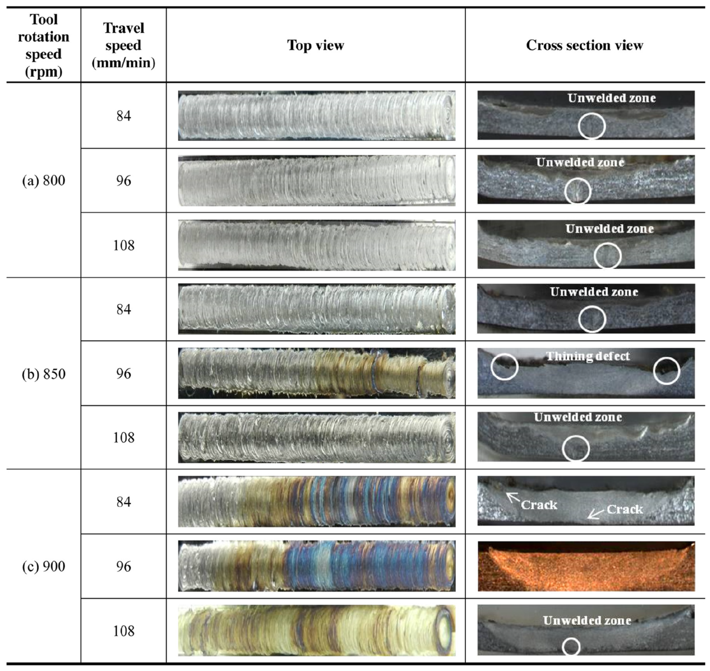
The green arrows in Figure 16a highlight the use of a pinless tool for the FSW of AISI 430M2 (s = 0.5 mm) [115]. Figure 23 shows the top and cross-sectional views for the tested process parameters. The best result was achieved at a welding speed of 96 mm/min and rotational speed of 900 rpm, reaching a tensile strength of 450 MPa (vs. about 460 MPa for the BM). A preheating source was introduced using a GTAW torch (current 30 A, voltage 30 V) to further explore the feasibility of this joint. This approach achieved a tensile strength of 475 MPa at a higher welding speed (300 mm/min), benefiting from the additional heat input provided by the GTAW torch [116]. Miyazawa et al. [96] investigated variations in the STC from 2.4 to 5.3 rpm/mm/min for AISI 304 steel (s = 1.5 mm). The authors recommended a minimum STC of 3.3 rpm/mm/min to avoid surface defects. Moreover, welding speeds exceeding 630 mm/min led to the formation of kissing-bond defects. However, the combination of rotational and welding speeds shown in Figure 16b produced joints with tensile strengths in the range of 675–705 MPa.
Chen et al. [130] studied S32707 duplex stainless steel (s = 3 mm) at a fixed welding speed of 100 mm/min with rotational speed in the range of 200–500 rpm. Their findings indicated that the austenite content in the SZ remained relatively consistent, 57–58% vs. 55% in the BM. Conversely, the ferritic phase increased significantly, from 12% at 200 rpm to 43% at 500 rpm (45% in the BM). In addition, the σ phase content was 31% at 200 rpm and 3% at 300 rpm, and was absent at 500 rpm, as well as in the BM. Kumar et al. [106] investigated the formation of the brittle δ-ferrite phase in FSW joints of AISI 316L austenitic stainless steel (s = 3 mm). Using a rotational speed of 600 rpm and welding speeds in the range of 25–100 mm/min, they found that the peak welding temperature reduced from 1150 °C at 25 mm/min to 700 °C at 100 mm/min. At 25 mm/min, the material entered the equilibrium region between the δ-ferrite and γ-austenite phases, resulting in the highest tensile strength (632 MPa), while 75 mm/min was identified as the optimal welding speed. Ragab et al. [117] studied 1Cr11Ni2W2MoV martensitic steel (s = 3.8 mm) with rotational speeds in the range 250–550 rpm at a fixed welding speed of 75 mm/min. They observed that the width of the SZ, TMAZ, and HAZ progressively increased with higher rotational speeds: from 13.5 to 14.5 mm for SZ, 0.97 mm to 2.2 mm for TMAZ, and 2.9 mm to 3.5 mm for HAZ. The δ-ferrite phase was absent in the SZ, except at 550 rpm, where a small fraction was detected at the top of the SZ. Jia et al. [126] focused on the FSW of S2205 duplex stainless steel (s = 4 mm) at a rotational speed of 600 rpm and welding speeds in the range of 30–70 mm/min. They found that ferrite content in the SZ decreased from 60% at the lowest to 50% at the highest, indicating the influence of welding speed on phase composition. A peak tensile strength of 825 MPa was achieved at a welding speed of 50 mm/min. 70 mm/min. Tunnel defects were noticed at a higher speed of 70 mm/min.
An investigation on AISI 410S (s = 4 mm) was conducted using a varying rotational speed in the range 450–800 rpm at a fixed welding speed of 60 mm/min, while vertical force ranged from 10 to 30 kN [114]. The cross-sections in Figure 24 show that the best results were achieved under conditions 2, 3, and 4. In contrast, condition 1 exhibited root flash, a defect normally caused by excessive vertical force during welding. However, the defect issue can also occur when both vertical force and rotational speed are too low, leading to insufficient friction between the tool and the material. The authors identified an optimal balance for their application using a vertical force of 20 kN and a tilt angle of 0°. Conditions 5 and 6 revealed voids in the root region of the SZ, attributed to inadequate parameters, such as low rotational speed and insufficient vertical force. Álvarez et al. [119] performed induction-assisted FSW on GX2CrNiMoN26-7-4 duplex stainless steel (s = 5 mm). The point of interest is marked with a black circle and green arrow in Figure 16f. Optimal process parameters were found in 250–500 rpm and 50–200 mm/min ranges. On the other hand, excessive heat input (e.g., abundant flash) and poor adherence to the backing plate occurred at 500 rpm and 50 mm/min. Tunnel defects on the AS were noticed at 350 rpm and 200 mm/min. Optimum results were obtained at 300 rpm and 100 mm/min under force control mode. The steady-state vertical force decreased from 26 to 18 kN when replicating the welding process through induction-assisted FSW.
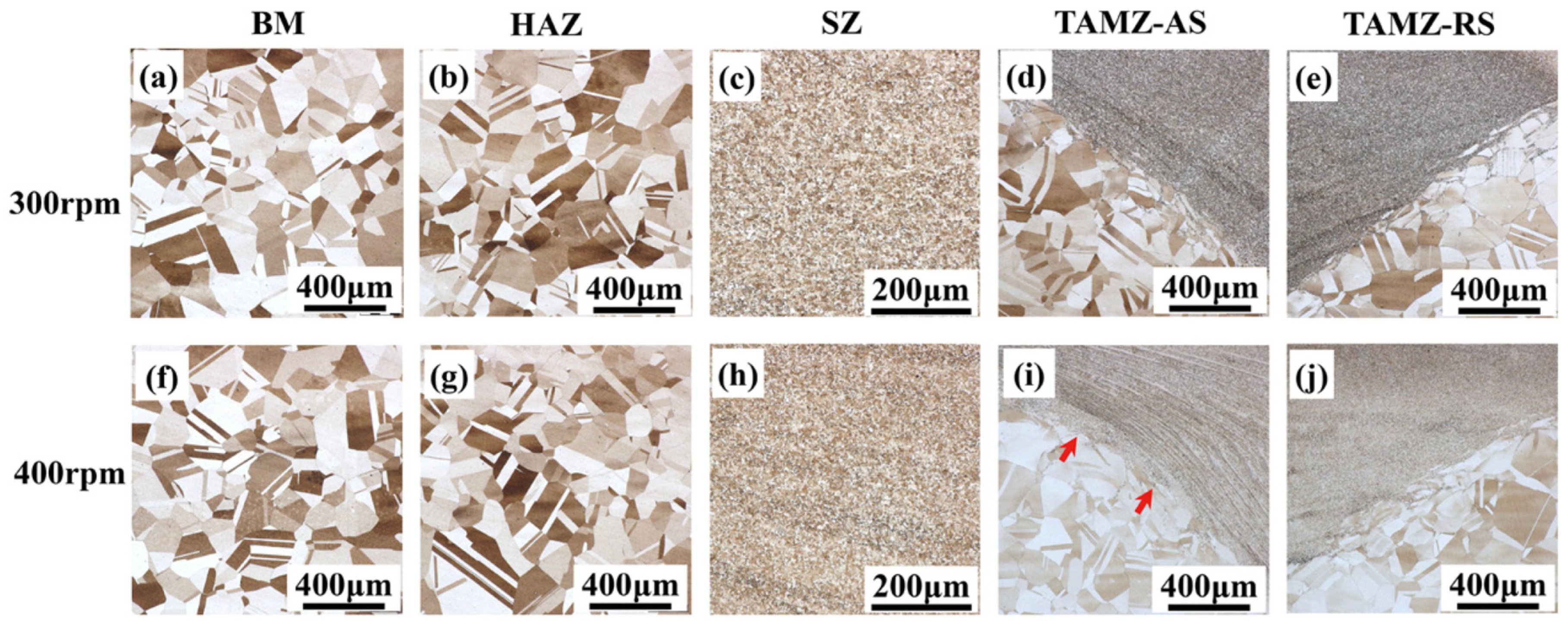
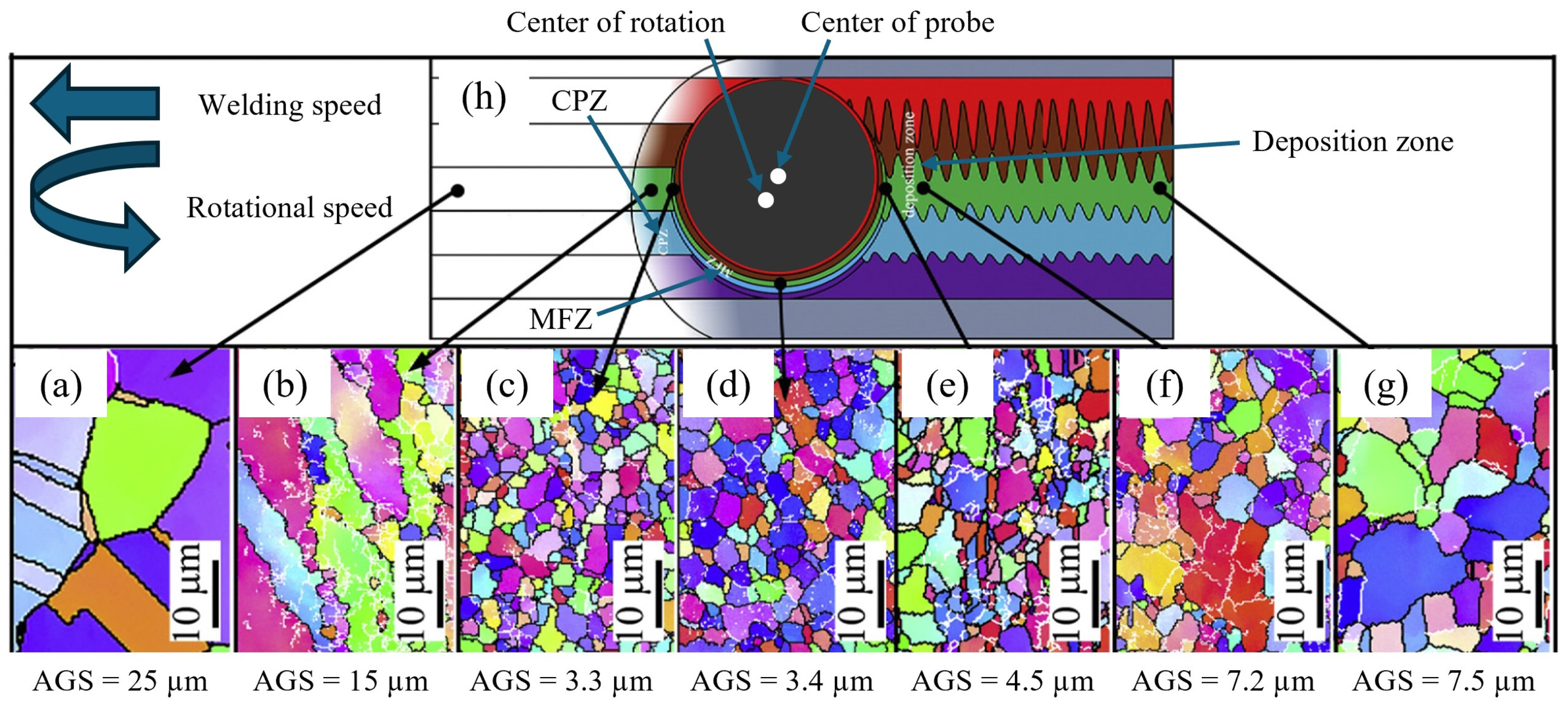
Liu et al. [102,103] studied the grain structure and texture evolution during the FSW of AISI 304L (s = 12.7 mm) at 250 rpm and 100 mm/min. Figure 25 illustrates the grain structure evolution around the tool during welding: (a) BM, (b) compression zone (CPZ), (c) material flow zone (MFZ) at the LS, (d) MFZ at the RS, (e) MFZ at the TS, (f) forge and torsion zone, (g) annealing zone, and (h) schematic of material flow. The phenomena experienced by the joint during welding can be divided into four stages. During stage I, the material approached the pin and was compressed, forming the CPZ. This region exhibited a high density of low-angle grain boundary (LAGB) segments, some of which transformed into long high-angle grain boundaries (HAGBs). Furthermore, discontinuous dynamic recrystallization (DDRX) generated fine equiaxed grains. In stage II, the material approached the MFZ. The coarse deformed grains in the CPZ evolved into fine equiaxed grains, mainly through DDRX and twinning. The MFZ, instead, underwent the following during stirring: (i) the fraction of LAGBs reduced, (ii) the ratio of twin boundaries increased, and (iii) the grain size distribution widened (even if the average grain size remained nearly constant). During this stage, the B component {112}〈110〉 formed in the MFZ, with its shear direction aligning with the local pin rotation and the shear plane approximately 30° from the pin surface. During stage III, grains started to grow as the material was stirred behind the pin. The forging action of the shoulder disrupted the twin boundaries formed in the MFZ and generated new LAGB segments. The B component weakened during this stage. After the shoulder passed, in stage IV, the material annealed. The density of LAGBs decreased, new twin boundaries developed, and the B component evolved into the C component {001}〈110〉.

3.4.5. Butt FSW of Maraging Steels

Meshram et al. performed FSW on MDN-250 maraging steel with a sheet thickness of 5.2 mm [137,138] and 5.5 mm [139]. In the first case, they tested a constant welding speed of 25 mm/min while varying the rotational speed in the range of 250–1050 rpm. At a fixed rotational speed of 250 rpm, welding speed was further varied, at 25–40 mm/min. Defect-free welds were obtained at 250 rpm and 25 mm/min. However, at 450 rpm, excessive heat generation prevented the formation of a weld nugget. When rotational speed increased from 650 to 1050 rpm, surface defects were enlarged, due to uncontrolled material flow attributed to elevated temperatures from high relative velocity at the tool–workpiece interface. Infrared thermography revealed that weld temperature increased with rotational speed, softening the weld and reducing its flow stress. This, combined with high metal velocity, caused unstable material flow and surface defects. Conversely, an increase above 25 mm/min resulted in insufficient material flow at the joint root, causing defects in that area. For 5.5 mm thick MDN-250, a higher rotational speed of 600 rpm was required while maintaining a welding speed of 25 mm/min. The hardness of the joint was assessed in both as-welded and post-weld-aged conditions. The BM exhibited a hardness of about 375 HV, which increased to approximately 500 HV near the outer edge of the TMAZ after aging. This increase was attributed to the solution-treated condition of the BM prior to welding. Within the HAZ, a distinct dark band region exhibited the lowest hardness (350 HV), caused by the fine dispersion of retained austenite in martensite. In the post-weld-aged condition, BM hardness further increased to 600–625 HV, with other regions exceeding this value except for the dark band region (575–600 HV).

3.4.6. Butt FSW of Titanium Alloys

Most studies on Ti alloys investigated ~2 mm thick Ti6Al4V, mainly exploring rotational and welding speeds in the ranges of 100–1500 rpm and 20–100 mm/min. Ji et al. [155,161] introduced back heating-assisted FSW to minimize temperature gradients along the sheet thickness and prevent tearing defects (highlighted with a black circle and grey arrow in Figure 16c). For conventional FSW of 2.5 mm thick Ti6Al4V, sound joints were only achieved at 100 rpm and 30 mm/min. Back-heating-assisted FSW broadened the process window to 100–150 rpm. The assisted heating preheated the material, enhancing plasticization and ensuring a more uniform temperature distribution. In contrast, conventional FSW generated significant thermal gradients through the metal thickness, particularly at rotation speeds above 100 rpm, which led to insufficient material flow in the lower regions of the joint and tearing defects. These defects consisted of internal voids or separations within the SZ, caused by inadequate bonding between material layers. For 2 mm thick Ti6Al4V, optimal parameters were identified as 350 rpm and 50 mm/min. Yue et al. [156] studied this thickness at a rotational speed ranging from 120 to 375 rpm at 50 mm/min. A large tunnel defect was observed at 375 rpm, which progressively reduced and disappeared at 120 rpm. At this lowest rotational speed, the peak temperature and temperature gradient (difference between the top and bottom surfaces) were minimized, reducing from about 105 °C at 350 rpm to 80 °C at 120 rpm.
Zhou et al. [151,152] investigated the FSW of 2 mm thick Ti6Al4V at varying rotational (400–600 rpm at 75 mm/min) and welding speeds (25–100 mm/min at 400 rpm). When the welding temperature remained below the β transus, the SZ exhibited a bimodal microstructure of primary α + transformed β with lamellar α + β, formed due to dynamic recrystallization during metal stirring. Increasing the welding speed from 25 to 100 mm/min promoted the growth of primary α while decreasing lamellar size, attributed to deformation and a fast cooling rate. At higher rotational (500–600 rpm) and welding speeds (75 mm/min), the SZ temperature exceeded the β transus, resulting in a fully lamellar microstructure with basket-weave α + β lamellae. From 500 rpm, the grain size of the prior β phase also increased. Kitamura et al. [153] extended the welding range of 2 mm thick Ti6Al4V to 300–1000 rpm and 25–400 mm/min. Their findings indicated that peak temperature was mainly influenced by rotational speed, while welding speed primarily affected cooling rate. Joint strength below the β transus temperature exceeded that of the BM, achieving about 1100 MPa at (i) 400 rpm and 100 mm/min and (ii) 1000 rpm and 400 mm/min (vs. about 1000 MPa for BM). When the peak temperature was over the β transus temperature, joint strength improved with increasing welding speed, because of the refinement of the lamellar α + β structure.
Figure 26 shows temperature-history curves for different rotational and welding speeds during the FSW of 2 mm thick Ti6Al4V [158,159]. Fujii et al. [140] investigated FSW of commercially pure Ti (s = 2 mm) at varying welding speeds (from 50 to 300 mm/min at 200 rpm). They observed a decrease in SZ temperature from 850 to 500 °C as welding speed increased. The maximum tensile strength, 450 MPa, was achieved at 200 mm/min (vs. 420 MPa for BM). Amirov et al. [150] studied Ti1.5Al1Mn (s = 2.5 mm) at varying rotational speeds (400–950 rpm), welding speeds (90–180 mm/min), and vertical forces (9.5–26 kN). Their results demonstrated that optimal FSW for this alloy requires lower rotational and welding speeds (<400 rpm and <100 mm/min) and higher vertical forces (>25 kN), differing from the typical process parameters used for Ti α-alloys. Gili et al. [168] investigated the FSW of Ti6Al4V (s = 3 mm) using a pinless tool at 950 rpm and 55 mm/min (refer to a black circle and grey arrow in Figure 16d). They changed the tilt angle (0°, 1°, and 2°) and the plunge depth (0.15–0.25 mm). At 0° tilt angle, SZ depth and required torque increased with plunge depth, ranging from 0.83 to 1.3 mm and 11–14 Nm, respectively. Tilt angles of 1° and 2° caused slight torque variations (12–13 Nm), due to reduced contact area, but SZ depth showed greater variability. At a 1° tilt angle, SZ depth decreased from 1.42 to 0.92 mm, while the maximum depth (2 mm) was achieved with a plunge depth of 0.2 mm. Buffa et al. [166] used the finite element method (FEM) to predict phase transformation during FSW of Ti6Al4V (s = 3 mm). Figure 27 shows the temperature distributions and the corresponding volume fractions of the α and β phases during welding, as well as the α and α + β phase distributions after cooling, for two process parameters sets: (a) 300 rpm and 50 mm/min, and (b) 700 rpm and 35 mm/min. The study concluded that peak welding temperature governs the formation of the β phase, which transforms into the α + β phase during cooling, determining the final microstructure.
Du et al. [148] widened the process window for Ti4Al0.005B (s = 5 mm) by replacing the conventional steel back-plate below the joint with a titanium support. Welding speeds were in the range of 25–50 mm/min at 250 rpm (refer to a black circle and grey arrow in Figure 16f). Tunnel defects were observed at the pin tip on the AS with both support types. However, these defects persisted with the steel back-plate, even at a low welding speed of 35 mm/min, due to insufficient heat input. Yoon et al. [171] investigated the FSW of Ti6Al4V joints (s = 5 mm) at rotational speeds of 50 rpm and 150 rpm at 10 mm/min. They observed a reduction in α grain size from the top to the root of the joint, attributed to the temperature gradient throughout the joint cross-section during welding (see Figure 28). This grain size variation led to a corresponding hardness reduction: from 380 HV at the top to 360 HV at the root for 50 rpm, and from 370 to 345 HV for 150 rpm. At 50 rpm, the SZ exhibited a fully equiaxed microstructure, while at 150 rpm, a small amount of lamellar microstructure was observed near the top surface, due to the higher peak temperature.
Edwards et al. [172] studied the FSW of Ti6Al4V (s = 6 mm) with varying rotational speeds of 200–400 rpm at 100 mm/min, and varying welding speeds of 50–100 mm/min at 300 rpm. To evaluate material flow patterns, tungsten–rhenium powder was embedded into the joint and welded through, with the welds subsequently inspected using radiography and metallography. Figure 29 shows the cross-sections of the welds, highlighting typical defects. At low ω/v ratios, a lack of penetration can be observed, as confirmed by the widespread horizontal distribution of the tracer material across the weld width but limited dispersion through the joint thickness. In contrast, high ω/v ratios caused excessive heat input, leading to void formation at the weld root. In these cases, the tracer material displayed a more vertical distribution, with minimal spread across the weld width in extreme cases.

3.4.7. Butt FSW of Nickel Alloys

Several studies [177,178,179,180] have investigated the processability of Inconel 600 (s = 2 mm) at varying welding speeds (100–450 mm/min) at 400 rpm. Figure 30 displays a) the temperature-history curve and b) the Hall–Petch relationship between grain size and hardness for the SZ in the 150–250 mm/min range. High welding speeds (300–450 mm/min, highlighted with a blue arrow in Figure 16c) were only achievable with a laser-based preheating system. The laser maintained higher joint temperatures during welding, ensuring proper material fusion and preventing defects at these high speeds. This approach led to increased productivity and a tensile strength improvement of 60 MPa over the BM (698 MPa). Sengupta et al. [182] used an electric-assisted external heating source to join Inconel 601 (s = 2 mm) at 1000–1100 rpm and 10–30 mm/min ranges (refer to a blue arrow in Figure 16c). This approach achieved a tensile strength 6% higher than that of the BM. Only one study [193] examined the FSW of Inconel 825 (s = 2 mm), using a high rotational speed of 2000 rpm at 75 mm/min. The study reported the formation of TiNi3, TiC, M6C, and M23C6 (M = Cr) precipitates, and TiCr2 at the grain boundaries. Grain refinement and formation of nano-precipitates significantly increased SZ hardness (from 170 to 280–320 HV). However, the tensile strength of the joint was 80% of the BM (708 MPa). Raj et al. [188,189] studied the FSW of Inconel 718 (s = 3 mm) at varying rotational speeds in the range 450–600 rpm at 90 mm/min. In all cases, joints exhibited groove-like defects, due to excessive welding speed. Reducing the rotational speed at 300 rpm and testing welding speed in the 40–140 mm/min range, optimal conditions were achieved at 90 mm/min. Lower welding speed resulted in wormholes or large cavities, due to insufficient plastic flow caused by excessive material temperature.
Process productivity was enhanced using high-frequency induction-assisted FSW at 140 mm/min (refer to black circles and blue arrows in Figure 16d) [189]. Ahmed et al. [192] focused on Inconel 718 (s = 4 mm) at welding speeds of 30–80 mm/min at 400 rpm. At 30 mm/min, the grain size decreases from about 4.3 μm (5 μm with 80 mm/min) at the weld face to about 2.1 μm (1.8 μm with 80 mm/min) at the weld root. This grain size variation was attributed to the different temperatures experienced during welding, with the higher thermal gradient at 80 mm/min accelerating grain refinement. Moreover, twin boundaries were more prevalent near the base of the SZ. The joint welded at 30 mm/min achieved a tensile strength of 823 MPa, and 715 MPa at 80 mm/min.

4. Conclusions

This review provides an in-depth and comprehensive analysis of FSW, highlighting its potential as an advanced technique for joining metal alloys across a wide range of industrial sectors. Developed by The Welding Institute (TWI) in 1991, FSW has revolutionized metal joining by minimizing thermal input compared to conventional fusion welding technologies, resulting in defect-free and more performant welds. Its versatility is appreciated in high-demanding industries such as aero-space, transportation, and advanced manufacturing, where joining dissimilar metal grades is critical. This review consolidated insights from 177 publications to examine the advancements, applications, and challenges of FSW across various materials, including magnesium (Mg) alloys, copper (Cu) alloys, automotive steels, stainless steels, maraging steels, titanium (Ti) alloys, and nickel (Ni) alloys. By analyzing the interplay between tool design, process parameters, and weld quality, several key findings were identified.

4.1. Advancements in Tool Design and Materials

The evolution of FSW tools has played a fundamental role in enhancing process efficiency and expanding its application range. Simpler tool designs, such as flat shoulders and cylindrical pins, consistently produce defect-free joints in Mg alloys (e.g., AZ31B and AM60). Adjusting tool dimensions proportional to sheet thickness ensures optimal stirring, while scrolled shoulders improve centerward material flow and reduce flash formation. Cu alloys benefit significantly from WC tools, which dominate due to their cost-effectiveness and durability. Pairing WC pins with HSS shoulders further reduces tool wear, while maintaining performance. For automotive steels, advanced tool materials such as WRe and PCBN composites accommodate the requirements of high-strength steels (e.g., dual-phase and TRIP grades). Convex shoulders and threaded-pin designs can enhance stirring efficiency and minimize voids. For Ti and Ni alloys, the challenges of high melting points and reactivity necessitate tailored solutions. Ti alloys primarily use flat shoulders, while Ni alloys benefit from scrolled and convex shoulders paired with PCBN tools to achieve superior weld quality.

4.2. Process Parameter Optimization

Process parameters such as rotational speed, welding speed, tilt angle, and plunge depth are critical to joint quality. For Mg alloys, high rotational speeds coupled with low welding speeds (e.g., 1700 rpm-100 mm/min) consistently produce high-quality joints. Cu alloys require higher rotational speeds (e.g., 1250–1600 rpm) for adequate heat generation. In automotive steels, parameter optimization is material-specific. For common DP600 steels, around 600 rpm and 250 mm/min can result in joints with optimal strengths, while HSLA steels required lower speeds, often coupled with higher vertical forces. Ti and Ni alloys demand more precise heat input control, due to their low thermal conductivity. For Ti6Al4V, rotational speeds of 700–800 rpm and welding speeds of 20–30 mm/min are quite common parameters for preventing defects such as voids and tunnels.

4.3. Material Flow and Microstructure

The FSW capability to refine microstructures and enhance mechanical properties is evident across all the studies reviewed. In Mg alloys, grain refinement in the SZ reduces grain size to a few microns (e.g., 3–5 µm). Cu alloys generally exhibit decreased hardness in the SZ due to recrystallization, but maintain acceptable weld strength. Automotive steels form more evident TMAZ and HAZ regions, with metal stirring also improving grain refinement in such materials. Ti alloys display significant grain refinement in the SZ, with the TMAZ features dependent on material strength and thermal conductivity. For Ni alloys, advanced tool designs ensure uniform microstructures and mitigate defects such as cracking and voids.

4.4. Challenges and Mitigation Strategies

Key challenges include tool wear, defect formation, and scalability. Wear-related issues are particularly significant in high-strength alloys, where advanced materials such as WRe and PCBN composites offer enhanced durability, albeit at a higher cost. Innovative tool designs like Whorl™ and MX-Triflute™ have demonstrated effectiveness in minimizing defects by optimizing material flow. However, these designs are less effective for high-strength alloys, due to wear and stress concentration challenges.
The future of FSW depends on its ability to evolve alongside emerging materials and application needs. Additive manufacturing and hybrid materials present exciting opportunities to leverage FSW versatility. The integration of real-time monitoring and control systems, driven by machine learning and sensor technologies, can significantly enhance process stability and weld quality. In sectors such as aerospace and automotives, where lightweight and high-strength materials are crucial, FSW capability to join dissimilar materials offers a competitive advantage. Advancing specialized tools and tailoring process parameters to these demanding applications are key priorities. Furthermore, environmentally conscious practices, such as minimizing energy consumption and emissions, align with sustainability objectives and strengthen the reputation of FSW as a preferred joining technology.

Author Contributions

Conceptualization, V.L., M.D.M., F.L. and P.R.S.; methodology, V.L., M.D.M., F.L. and P.R.S.; formal analysis, V.L., M.D.M., F.L. and P.R.S.; investigation, V.L., M.D.M., F.L. and P.R.S.; writing—original draft preparation, V.L., M.D.M., F.L. and P.R.S.; writing—review and editing, V.L., M.D.M., F.L. and P.R.S.; All authors have read and agreed to the published version of the manuscript.

Funding

This research received no external funding.

Data Availability Statement

Compliance with ethical standards.

Acknowledgments

This study was supported by the Advanced Joining Technologies Laboratory J-Tech@Polito at Politecnico di Torino, http://www.j-tech.polito.it (accessed on 17 January 2025).

Conflicts of Interest

The authors declare no conflicts of interest.

References

  1. Wayne, T. Friction Welding. U.S. Patent 5,460,317, 24 October 1995. Available online: https://patentimages.storage.googleapis.com/66/60/ad/5f784d0b8653b7/US5460317.pdf (accessed on 17 January 2025).
  2. The Welding Institute Last Time. Available online: https://www.twi-global.com (accessed on 17 January 2025).
  3. Lunetto, V.; De Maddis, M.; Russo Spena, P. Pre-hole friction stir spot welding of dual-phase steels and comparison with resistance spot welding, conventional and pinless friction stir spot welding. Int. J. Adv. Manuf. Technol. 2023, 129, 2333–2349. [Google Scholar] [CrossRef]
  4. Mirandola, P.; Lunetto, V.; Novel, D.; Barozzi, M.; Bellutti, P.; De Maddis, M.; Russo Spena, P. Strength and microstructure of friction stir welded additively manufactured Scalmalloy® in as-welded and heat-treated conditions. J. Manuf. Process. 2023, 97, 1–11. [Google Scholar] [CrossRef]
  5. Mirandola, P.; Novel, D.; Perini, M.; Benedetti, M.; Lombardi, F.; Lunetto, V.; Spena, P.R. Microstructures and mechanical properties of friction stir welded additively manufactured Scalmalloy®. Int. J. Adv. Manuf. Technol. 2024, 134, 1645–1660. [Google Scholar] [CrossRef]
  6. Svoboda, H.G.; Tufaro, L.N.; Leitão, C.; Rodrigues, D.M. Dissimilar Friction Stir Lap Welding of Aluminium to Steel: Influence of Alloy Type and Sheet Thickness on Strain Distribution and Failure Location. J. Manuf. Mater. Process. 2023, 7, 221. [Google Scholar] [CrossRef]
  7. Li, Q.; Ma, Z.; Ji, S.; Song, Q.; Gong, P.; Li, R. Effective joining of Mg/Ti dissimilar alloys by friction stir lap welding. J. Mater. Process. Technol. 2020, 278, 116483. [Google Scholar] [CrossRef]
  8. Nagatsuka, K.; Yoshida, S.; Tsuchiya, A.; Nakata, K. Direct joining of carbon-fiber–reinforced plastic to an aluminum alloy using friction lap joining. Compos. Part B Eng. 2015, 73, 82–88. [Google Scholar] [CrossRef]
  9. Lunetto, V.; Basile, D.; Razza, V.; Russo Spena, P. Active and Passive Filling Stir Repairing of AISI 304 Alloy. Metals 2024, 14, 911. [Google Scholar] [CrossRef]
  10. Lunetto, V.; Catalano, A.R.; Priarone, P.C.; Settineri, L. Comments About the Human Health Risks Related to Additive Manufacturing. In Smart Innovation, Systems and Technologies; Springer: Berlin/Heidelberg, Germany, 2019; Volume 130, pp. 95–104. [Google Scholar] [CrossRef]
  11. Catalano, A.R.; Lunetto, V.; Priarone, P.C.; Settineri, L. A Survey on Energy Efficiency in Metal Wire Deposition Processes. In Smart Innovation, Systems and Technologies; Springer: Berlin/Heidelberg, Germany, 2019; Volume 155, pp. 311–322. [Google Scholar] [CrossRef]
  12. Sunnapu, C.; Kolli, M. Tool shoulder and pin geometry’s effect on friction stir welding: A study of literature. Mater. Today Proc. 2021, 39, 1565–1569. [Google Scholar] [CrossRef]
  13. Lunetto, V.; De Maddis, M.; Russo Spena, P. Similar and dissimilar lap friction stir welding of titanium alloys: On the elimination of the hook defect. Int. J. Adv. Manuf. Technol. 2023, 126, 3417–3435. [Google Scholar] [CrossRef]
  14. Abankar, M.; Lunetto, V.; De Maddis, M.; Russo Spena, P. Friction stir welding of additively manufactured A20X aluminum alloy: Welding process, mechanical properties, and microstructure. Int. J. Adv. Manuf. Technol. 2024, 135, 4635–4652. [Google Scholar] [CrossRef]
  15. Orlando, M.; De Maddis, M.; Razza, V.; Lunetto, V. Non-destructive detection and analysis of weld defects in dissimilar pulsed GMAW and FSW joints of aluminium castings and plates through 3D X-ray computed tomography. Int. J. Adv. Manuf. Technol. 2024, 132, 2957–2970. [Google Scholar] [CrossRef]
  16. Lemos, G.V.B.; Hanke, S.; Dos Santos, J.F.; Bergmann, L.; Reguly, A.; Strohaecker, T.R. Progress in friction stir welding of Ni alloys. Sci. Technol. Weld. Join. 2017, 22, 643–657. [Google Scholar] [CrossRef]
  17. Wahid, M.A.; Khan, Z.A.; Siddiquee, A.N. Review on underwater friction stir welding: A variant of friction stir welding with great potential of improving joint properties. Trans. Nonferrous Met. Soc. China 2018, 28, 193–219. [Google Scholar] [CrossRef]
  18. Mengran, Z.; Yufeng, S.; Yoshiaki, M.; Kohsaku, U.; Hidetoshi, F. Quasi-in-situ investigation into the microstructure and texture evolution of pure magnesium during friction stir welding. J. Magnes. Alloys 2020, 8, 1071–1083. [Google Scholar] [CrossRef]
  19. Li, Z.; Ding, H.; Chen, Y.; Li, J.; Liu, L. Strain Accumulation and Microstructural Evolution During Friction Stir Welding of Pure Magnesium. Front. Mater. 2020, 7, 603464. [Google Scholar] [CrossRef]
  20. Chiuzuli, F.R.; Batistão, B.F.; Bergmann, L.A.; de Alcântara, N.G.; dos Santos, J.F.; Klusemann, B.; Gargarella, P. Effect of the gap width in AZ31 magnesium alloy joints obtained by friction stir welding. J. Mater. Res. Technol. 2021, 15, 5297–5306. [Google Scholar] [CrossRef]
  21. He, F.; Wu, C.; Shi, L. Multiphase field simulation of dynamic recrystallization during friction stir welding of AZ31 magnesium alloy. J. Mater. Sci. 2022, 57, 20764–20779. [Google Scholar] [CrossRef]
  22. Wang, W.; Han, P.; Qiao, K.; Li, T.; Wang, K.; Cai, J.; Wang, L. Effect of the rotation rate on the low-cycle fatigue behavior of friction-stir welded AZ31 magnesium alloy. Eng. Fract. Mech. 2020, 228, 106925. [Google Scholar] [CrossRef]
  23. Han, Y.; Jiang, X.; Chen, S.; Yuan, T.; Zhang, H.; Bai, Y.; Xiang, Y.; Li, X. Microstructure and mechanical properties of electrically assisted friction stir welded AZ31B alloy joints. J. Manuf. Process. 2019, 43, 26–34. [Google Scholar] [CrossRef]
  24. Thakur, A.; Sharma, V.; Bhadauria, S.S. Effect of tool tilt angle on weld joint strength and microstructural characterization of double-sided friction stir welding of AZ31B magnesium alloy. CIRP J. Manuf. Sci. Technol. 2021, 35, 132–145. [Google Scholar] [CrossRef]
  25. Saini, S.; Chohan, J.S.; Boparai, K.S. Evaluating the microstructural characteristics in friction stir welding of magnesium AZ61a alloy. Mater. Today Proc. 2021, 48, 1762–1768. [Google Scholar] [CrossRef]
  26. Zhou, M.; Morisada, Y.; Fujii, H. Effect of Ca addition on the microstructure and the mechanical properties of asymmetric double-sided friction stir welded AZ61 magnesium alloy. J. Magnes. Alloys 2020, 8, 91–102. [Google Scholar] [CrossRef]
  27. Singh, K.; Singh, G.; Singh, H. Microstructural and Mechanical Behaviour Evaluation of Mg-Al-Zn Alloy Friction Stir Welded Joint. Int. J. Automot. Mech. Eng. 2020, 17, 8150–8159. [Google Scholar] [CrossRef]
  28. Zhou, M.; Morisada, Y.; Fujii, H.; Wang, J.-Y. Microstructure and mechanical properties of friction stir welded duplex Mg–Li alloy LZ91. Mater. Sci. Eng. A 2020, 773, 138730. [Google Scholar] [CrossRef]
  29. Sahu, P.K.; Pal, S.; Das, B.; Shi, Q. Fabrication and effect of Mg–Zn solid solution via Zn foil interlayer alloying in FSW process of magnesium alloy. Arch. Civ. Mech. Eng. 2020, 20, 137. [Google Scholar] [CrossRef]
  30. Cyril Joseph Daniel, S.; Lakshminarayanan, A.K. Comparative Study of Friction Stir Welding and Underwater Friction Stir Welding on Magnesium ZE41 Alloy; Springer: Singapore, 2021. [Google Scholar] [CrossRef]
  31. Zhang, J.; Chen, X.; Xia, D.; Huang, G.; Tang, A.; Jiang, B.; Pan, F. Improving performance of friction stir welded AZ31/AM60 dissimilar joint by adjusting texture distribution and microstructure. Mater. Sci. Eng. A 2020, 778, 139088. [Google Scholar] [CrossRef]
  32. Zhang, J.; Huang, Y.; Xiang, J.; Huang, G.; Chen, X.; Zhou, H.; Jiang, B.; Tang, A.; Pan, F. Characterization of newly developed friction stir-arc welding method for AM60/AZ31 dissimilar Mg alloy. Mater. Sci. Eng. A 2021, 800, 140320. [Google Scholar] [CrossRef]
  33. Maruthapandian, M.; Pugazhenhi, R.; Gnanavel, C. Study the impaction tool speed on the friction stir welding of magnesium alloys plates. Mater. Today Proc. 2022, 69, 832–836. [Google Scholar] [CrossRef]
  34. Singh, U.K.; Dubey, A.K. Study of Weld Characteristics in Friction Stir Welding of Dissimilar Mg-Al-Zn Magnesium Alloys under Varying Welding Conditions. J. Mater. Eng. Perform. 2021, 30, 7690–7703. [Google Scholar] [CrossRef]
  35. Xu, N.; Feng, R.-N.; Guo, W.-F.; Song, Q.-N.; Bao, Y.-F. Effect of Zener–Hollomon Parameter on Microstructure and Mechanical Properties of Copper Subjected to Friction Stir Welding. Acta Metall. Sin. Engl. Lett. 2020, 33, 319–326. [Google Scholar] [CrossRef]
  36. Xu, N.; Ueji, R.; Fujii, H. Dynamic and static change of grain size and texture of copper during friction stir welding. J. Mater. Process. Technol. 2016, 232, 90–99. [Google Scholar] [CrossRef]
  37. Shen, J.J.; Liu, H.J.; Cui, F. Effect of welding speed on microstructure and mechanical properties of friction stir welded copper. Mater. Des. 2010, 31, 3937–3942. [Google Scholar] [CrossRef]
  38. Constantin, M.A.; Nitu, E.L.; Iordache, D.M.; Badulescu, C. Study on the influence of technological parameters on the friction stir butt welding process of pure copper plates. IOP Conf. Ser. Mater. Sci. Eng. 2020, 968, 012013. [Google Scholar] [CrossRef]
  39. Yaghoubi, M.A.; Anjabin, N. Friction stir welding of severely deformed copper sheets: Microstructure and mechanical properties. Mater. Sci. Technol. 2023, 39, 474–484. [Google Scholar] [CrossRef]
  40. Sahlot, P.; Singh, A.K.; Badheka, V.J.; Arora, A. Friction Stir Welding of Copper: Numerical Modeling and Validation. Trans. Indian Inst. Met. 2019, 72, 1339–1347. [Google Scholar] [CrossRef]
  41. Hwang, Y.M.; Fan, P.L.; Lin, C.H. Experimental study on Friction Stir Welding of copper metals. J. Mater. Process. Technol. 2010, 210, 1667–1672. [Google Scholar] [CrossRef]
  42. Karrar, G.; Shuaib, A.N.; Al-Badour, F.A.; Merah, N.; Mahgoub, A.K. Friction Stir Butt Welding of Commercially Pure Copper Plates. In Proceedings of the ASME 2014 International Mechanical Engineering Congress and Exposition, Montreal, QC, Canada, 14–20 November 2014; American Society of Mechanical Engineers: New York, NY, USA, 2014; Volume 2A Advanced Manufacturing, pp. 1–7. [Google Scholar] [CrossRef]
  43. Mironov, S.; Inagaki, K.; Sato, Y.S.; Kokawa, H. Microstructural evolution of pure copper during friction-stir welding. Philos. Mag. 2015, 95, 367–381. [Google Scholar] [CrossRef]
  44. Nia, A.A.; Shirazi, A. Effects of different friction stir welding conditions on the microstructure and mechanical properties of copper plates. Int. J. Miner. Metall. Mater. 2016, 23, 799–809. [Google Scholar] [CrossRef]
  45. Machniewicz, T.; Nosal, P.; Korbel, A.; Hebda, M. Effect of FSW Traverse Speed on Mechanical Properties of Copper Plate Joints. Materials 2020, 13, 1937. [Google Scholar] [CrossRef] [PubMed]
  46. Pashazadeh, H.; Teimournezhad, J.; Masoumi, A. Numerical investigation on the mechanical, thermal, metallurgical and material flow characteristics in friction stir welding of copper sheets with experimental verification. Mater. Des. 2014, 55, 619–632. [Google Scholar] [CrossRef]
  47. Xu, N.; Song, Q.-N.; Bao, Y.-F. Improvement of microstructure and mechanical properties of C44300 tin brass subjected to double-pass rapid cooling friction stir welding. J. Alloys Compd. 2020, 834, 155052. [Google Scholar] [CrossRef]
  48. Mironov, S.; Inagaki, K.; Sato, Y.S.; Kokawa, H. Development of grain structure during friction-stir welding of Cu–30Zn brass. Philos. Mag. 2014, 94, 3137–3148. [Google Scholar] [CrossRef]
  49. Xu, N.; Ueji, R.; Fujii, H. Enhanced mechanical properties of 70/30 brass joint by rapid cooling friction stir welding. Mater. Sci. Eng. A 2014, 610, 132–138. [Google Scholar] [CrossRef]
  50. Xu, N.; Ueji, R.; Fujii, H. Enhanced mechanical properties of 70/30 brass joint by multi-pass friction stir welding with rapid cooling. Sci. Technol. Weld. Join. 2015, 20, 91–99. [Google Scholar] [CrossRef]
  51. Xu, N.; Chen, L.; Feng, R.N.; Song, Q.N.; Bao, Y.F. Recrystallization of Cu-30Zn brass during friction stir welding. J. Mater. Res. Technol. 2020, 9, 3746–3758. [Google Scholar] [CrossRef]
  52. Meran, C. The joint properties of brass plates by friction stir welding. Mater. Des. 2006, 27, 719–726. [Google Scholar] [CrossRef]
  53. Heidarzadeh, A.; Barenji, R.V.; Khalili, V.; Güleryüz, G. Optimizing the friction stir welding of the α/β brass plates to obtain the highest strength and elongation. Vacuum 2019, 159, 152–160. [Google Scholar] [CrossRef]
  54. Ozer, A.; Sik, A.; Cevik, B.; Ozer, M. The effect of friction stir welding parameters on microstructure and fatigue strength of CuZn37 brass alloys. Met. Mater. 2017, 55, 107–114. [Google Scholar] [CrossRef]
  55. Xie, G.M.; Ma, Z.Y.; Geng, L. Effects of Friction Stir Welding Parameters on Microstructures and Mechanical Properties of Brass Joints. Mater. Trans. 2008, 49, 1698–1701. [Google Scholar] [CrossRef]
  56. Emamikhah, A.; Abbasi, A.; Atefat, A.; Givi, M.K.B. Effect of tool pin profile on friction stir butt welding of high-zinc brass (CuZn40). Int. J. Adv. Manuf. Technol. 2014, 71, 81–90. [Google Scholar] [CrossRef]
  57. Xu, N.; Chen, L.; Gu, B.; Ren, Z.; Song, Q.; Bao, Y. Heterogeneous structure-induced strength and ductility synergy of α-brass subjected to rapid cooling friction stir welding. Trans. Nonferrous Met. Soc. China 2021, 31, 3785–3799. [Google Scholar] [CrossRef]
  58. Zhou, L.; Xu, F.; Yu, M.; Jiang, Z.; Zhao, D.; He, W.; Huang, Y. Microstructural Characteristics and Mechanical Properties of Friction-Stir-Welded CuSn6 Tin Bronze. J. Mater. Eng. Perform. 2019, 28, 4477–4484. [Google Scholar] [CrossRef]
  59. Zhou, L.; Jiang, Z.H.; Zhao, D.G.; Yu, M.R.; Zhao, H.Y.; Huang, Y.X.; Song, X.G. Effect of Rotation Speed on the Microstructure and Mechanical Properties of Friction-Stir-Welded CuSn6 Tin Bronze. J. Mater. Eng. Perform. 2018, 27, 5581–5590. [Google Scholar] [CrossRef]
  60. Rizi, M.S.; Kokabi, A.H. Microstructure evolution and microhardness of friction stir welded cast aluminum bronze. J. Mater. Process. Technol. 2014, 214, 1524–1529. [Google Scholar] [CrossRef]
  61. Selvaraju, S.; Senthamaraikannan, S.; Jayaprakasham, S.; Madiq, A.R. Effect of Process Parameters on Microstructure and Mechanical Properties of Friction Stir Welded Cast Nickel Aluminum Bronze Alloy (C95800). Mater. Res. 2018, 21, 139277. [Google Scholar] [CrossRef]
  62. Siva, S.; Sampathkumar, S.; Sudha, J. Microstructure and Mechanical Properties of Exothermic-Reaction-Assisted Friction-Stir-Welded Nickel-Aluminum Bronze Alloy. J. Mater. Eng. Perform. 2019, 28, 2256–2270. [Google Scholar] [CrossRef]
  63. Küçükömeroğlu, T.; Şentürk, E.; Kara, L.; İpekoğlu, G.; Çam, G. Microstructural and Mechanical Properties of Friction Stir Welded Nickel-Aluminum Bronze (NAB) Alloy. J. Mater. Eng. Perform. 2016, 25, 320–326. [Google Scholar] [CrossRef]
  64. Zhang, C.; Qin, Z.; Rong, C.; Shi, W.; Wang, S. The Preliminary Exploration of Micro-Friction Stir Welding Process and Material Flow of Copper and Brass Ultra-Thin Sheets. Materials 2020, 13, 2401. [Google Scholar] [CrossRef] [PubMed]
  65. Erdem, M. Investigation of structure and mechanical properties of copper-brass plates joined by friction stir welding. Int. J. Adv. Manuf. Technol. 2015, 76, 1583–1592. [Google Scholar] [CrossRef]
  66. Ramesh, C.; Tharwan, M.; Kumar, P.M.; Gebreyohannes, D.T. Microstructural and Mechanical Characteristics of Pure-Cu/brass Dissimilar Joints Welded by Friction Stir Welding Using Various Process Parameters. Adv. Mater. Sci. Eng. 2022, 2022, 2234352. [Google Scholar] [CrossRef]
  67. Murugan, R.; Thirumalaisamy, N. Experimental and numerical analysis of friction stir welded dissimilar copper and bronze plates. Mater. Today Proc. 2018, 5, 803–809. [Google Scholar] [CrossRef]
  68. Fujii, H.; Cui, L.; Tsuji, N.; Maeda, M.; Nakata, K.; Nogi, K. Friction stir welding of carbon steels. Mater. Sci. Eng. A 2006, 429, 50–57. [Google Scholar] [CrossRef]
  69. Fujii, H.; Cui, L.; Nakata, K.; Nogi, K. Mechanical Properties of Friction Stir Welded Carbon Steel Joints—Friction Stir Welding with and without Transformation. Weld. World 2008, 52, 75–81. [Google Scholar] [CrossRef]
  70. Fujii, H.; Ueji, R.; Takada, Y.; Kitahara, H.; Tsuji, N.; Nakata, K.; Nogi, K. Friction Stir Welding of Ultrafine Grained Interstitial Free Steels. Mater. Trans. 2006, 47, 239–242. [Google Scholar] [CrossRef]
  71. You, H.; Kang, M.; Yi, S.; Hyun, S.; Kim, C. Comprehensive Analysis of the Microstructure and Mechanical Properties of Friction-Stir-Welded Low-Carbon High-Strength Steels with Tensile Strengths Ranging from 590 MPa to 1.5 GPa. Appl. Sci. 2021, 11, 5728. [Google Scholar] [CrossRef]
  72. Kim, Y.G.; Kim, J.S.; Kim, I.J. Effect of process parameters on optimum welding condition of DP590 steel by friction stir welding. J. Mech. Sci. Technol. 2014, 28, 5143–5148. [Google Scholar] [CrossRef]
  73. Miles, M.P.; Pew, J.; Nelson, T.W.; Li, M. Comparison of formability of friction stir welded and laser welded dual phase 590 steel sheets. Sci. Technol. Weld. Join. 2006, 11, 384–388. [Google Scholar] [CrossRef]
  74. Küçükömeroğlu, T.; Aktarer, S.M.; Çam, G. Investigation of mechanical and microstructural properties of friction stir welded dual phase (DP) steel. IOP Conf. Ser. Mater. Sci. Eng. 2019, 629, 012010. [Google Scholar] [CrossRef]
  75. Mahmoudiniya, M.; Kokabi, A.H.; Kheirandish, S.; Kestens, L.A.I. Microstructure and mechanical properties of friction stir welded ferrite-martensite DP700 steel. Mater. Sci. Eng. A 2018, 737, 213–222. [Google Scholar] [CrossRef]
  76. Mahmoudiniya, M.; Kokabi, A.H.; Goodarzi, M.; Kestens, L.A.I. Friction stir welding of advanced high strength dual phase steel: Microstructure, mechanical properties and fracture behavior. Mater. Sci. Eng. A 2020, 769, 138490. [Google Scholar] [CrossRef]
  77. Mahmoudiniya, M.; Kokabi, A.H.; Goodarzi, M.; Kestens, L.A.I. The Effect of Improved Cooling on the Microstructure and Mechanical Properties of Friction Stir-Welded Advanced High-Strength Dual-Phase Steel. Steel Res. Int. 2021, 92, 2000253. [Google Scholar] [CrossRef]
  78. Lee, H.; Kim, C.; Song, J. An Evaluation of Global and Local Tensile Properties of Friction-Stir Welded DP980 Dual-Phase Steel Joints Using a Digital Image Correlation Method. Materials 2015, 8, 8424–8436. [Google Scholar] [CrossRef] [PubMed]
  79. Ramesh, R.; Dinaharan, I.; Kumar, R.; Akinlabi, E.T. Microstructure and mechanical characterization of friction stir welded high strength low alloy steels. Mater. Sci. Eng. A 2017, 687, 39–46. [Google Scholar] [CrossRef]
  80. Ragu Nathan, S.; Balasubramanian, V.; Malarvizhi, S.; Rao, A.G. Effect of Tool Shoulder Diameter on Stir Zone Characteristics of Friction Stir Welded HSLA Steel Joints. Trans. Indian Inst. Met. 2016, 69, 1861–1869. [Google Scholar] [CrossRef]
  81. Ragu Nathan, S.; Balasubramanian, V.; Malarvizhi, S.; Rao, A. Effect of D/T P ratio on stir zone characteristics of friction stir-welded high-strength low-alloy steel plates. Proc. Inst. Mech. Eng. Part L J. Mater. Des. Appl. 2018, 232, 829–840. [Google Scholar] [CrossRef]
  82. Barnes, S.J.; Bhatti, A.R.; Steuwer, A.; Johnson, R.; Altenkirch, J.; Withers, P.J. Friction Stir Welding in HSLA-65 Steel: Part I. Influence of Weld Speed and Tool Material on Microstructural Development. Metall. Mater. Trans. A 2012, 43, 2342–2355. [Google Scholar] [CrossRef]
  83. Steuwer, A.; Barnes, S.J.; Altenkirch, J.; Johnson, R.; Withers, P.J. Friction Stir Welding of HSLA-65 Steel: Part II. The Influence of Weld Speed and Tool Material on the Residual Stress Distribution and Tool Wear. Metall. Mater. Trans. A 2012, 43, 2356–2365. [Google Scholar] [CrossRef]
  84. Shaysultanov, D.; Raimov, K.; Stepanov, N.; Zherebtsov, S. Friction Stir Welding of a TRIP Fe49Mn30Cr10Co10C1 High Entropy Alloy. Metals 2020, 11, 66. [Google Scholar] [CrossRef]
  85. Das, H.; Mondal, M.; Hong, S.-T.; Lee, K.-J.; Chattopadhyay, K. Microstructure and mechanical properties evaluation of friction stir welded boron steel. J. Mech. Sci. Technol. 2020, 34, 2011–2017. [Google Scholar] [CrossRef]
  86. Buzolin, R.H.; Francisco, B.R.; da Silva, E.P.; Pereira, V.F.; Ramirez Londono, A.J.; Maluf, O.; Pinto, H.C. Dissimilar Friction Stir Welding of HSLA Steel to Austenitic High-Mn TRIP Steel. Mater. Sci. Forum 2016, 879, 2306–2311. [Google Scholar] [CrossRef]
  87. Kim, H.-J.; Fujii, H.; Lee, S.-J. Corrosion Behavior and Microstructure of Stir Zone in Fe-30Mn-3Al-3Si Twinning-Induced Plasticity Steel after Friction Stir Welding. Metals 2020, 10, 1557. [Google Scholar] [CrossRef]
  88. Lee, S.-J.; Ushioda, K.; Fujii, H. Evaluation of stacking-fault energy in Fe-Mn based twinning-induced plasticity steels after friction stir welding. Mater. Charact. 2019, 147, 379–383. [Google Scholar] [CrossRef]
  89. Lee, S.-J.; Sun, Y.; Fujii, H. Stacking-fault energy, mechanical twinning and strain hardening of Fe-18Mn-0.6C-(0, 1.5)Al twinning-induced plasticity steels during friction stir welding. Acta Mater. 2018, 148, 235–248. [Google Scholar] [CrossRef]
  90. Tiwari, A.; Pankaj, P.; Biswas, P.; Kore, S.D.; Rao, A.G. Tool performance evaluation of friction stir welded shipbuilding grade DH36 steel butt joints. Int. J. Adv. Manuf. Technol. 2019, 103, 1989–2005. [Google Scholar] [CrossRef]
  91. Almoussawi, M.; Smith, A.J.; Faraji, M.; Cater, S. Segregation of Mn, Si, Al, and Oxygen During the Friction Stir Welding of DH36 Steel. Metallogr. Microstruct. Anal. 2017, 6, 569–576. [Google Scholar] [CrossRef]
  92. Al-moussawi, M.; Smith, A.J.; Young, A.; Cater, S.; Faraji, M. Modelling of friction stir welding of DH36 steel. Int. J. Adv. Manuf. Technol. 2017, 92, 341–360. [Google Scholar] [CrossRef]
  93. Toumpis, A.; Galloway, A.; Cater, S.; McPherson, N. Development of a process envelope for friction stir welding of DH36 steel—A step change. Mater. Des. 2014, 62, 64–75. [Google Scholar] [CrossRef]
  94. Wang, Z.W.; Zhang, J.F.; Xie, G.M.; Wu, L.H.; Zhang, H.; Xue, P.; Ni, D.R.; Xiao, B.L.; Ma, Z.Y. Evolution mechanisms of microstructure and mechanical properties in a friction stir welded ultrahigh-strength quenching and partitioning steel. J. Mater. Sci. Technol. 2022, 102, 213–223. [Google Scholar] [CrossRef]
  95. Wang, Z.W.; Zhang, H.; An, X.H.; Wu, L.H.; Xue, P.; Zhang, Q.C.; Ni, D.R.; Xiao, B.L.; Ma, Z.Y. Achieving equal strength joint to parent metal in a friction stir welded ultra-high strength quenching and partitioning steel. Mater. Sci. Eng. A 2020, 793, 139979. [Google Scholar] [CrossRef]
  96. Miyazawa, T.; Iwamoto, Y.; Maruko, T.; Fujii, H. Friction stir welding of 304 stainless steel using Ir based alloy tool. Sci. Technol. Weld. Join. 2012, 17, 207–212. [Google Scholar] [CrossRef]
  97. Hajizadeh, M.; Emami, S.; Saeid, T. Influence of welding speed on microstructure formation in friction-stir-welded 304 austenitic stainless steels. Int. J. Miner. Metall. Mater. 2020, 27, 1517–1524. [Google Scholar] [CrossRef]
  98. Das, H.; Das, C.R.; Divya, M.; Albert, S.K.; Pal, T.K. Friction Stir Welding: A Solution to Avoid Weld Cracking in Borated Stainless Steel. J. Mater. Eng. Perform. 2020, 29, 7765–7773. [Google Scholar] [CrossRef]
  99. Plaine, A.H.; de Alcântara, N.G. Prediction of Friction Stir Welding defect-free joints of AISI 304 austenitic stainless steel through axial force profile understanding. Mater. Res. 2014, 17, 1324–1327. [Google Scholar] [CrossRef]
  100. Siddiquee, A.N.; Pandey, S. Experimental investigation on deformation and wear of WC tool during friction stir welding (FSW) of stainless steel. Int. J. Adv. Manuf. Technol. 2014, 73, 479–486. [Google Scholar] [CrossRef]
  101. Siddiquee, A.N.; Pandey, S.; Khan, N.Z. Friction Stir Welding of Austenitic Stainless Steel: A Study on Microstructure and Effect of Parameters on Tensile Strength. Mater. Today Proc. 2015, 2, 1388–1397. [Google Scholar] [CrossRef]
  102. Liu, F.C.; Nelson, T.W. In-situ material flow pattern around probe during friction stir welding of austenitic stainless steel. Mater. Des. 2016, 110, 354–364. [Google Scholar] [CrossRef]
  103. Liu, F.C.; Nelson, T.W. In-situ grain structure and texture evolution during friction stir welding of austenite stainless steel. Mater. Des. 2017, 115, 467–478. [Google Scholar] [CrossRef]
  104. Naskar, A.; Bhattacharyya, M.; Raja, K.S.; Charit, I.; Darsell, J.; Jana, S. Room temperature corrosion behaviour of plastically deformed AISI 304 stainless steel by friction stir welding in neutral and acidified chloride solutions. Corros. Eng. Sci. Technol. 2022, 57, 599–612. [Google Scholar] [CrossRef]
  105. Guo, R.; Shen, Y.; Huang, G.; Zhang, W.; Guan, W. Microstructures and mechanical properties of thin 304 stainless steel sheets by friction stir welding. J. Adhes. Sci. Technol. 2018, 32, 1313–1323. [Google Scholar] [CrossRef]
  106. Shashi Kumar, S.; Murugan, N.; Ramachandran, K.K. Effect of friction stir welding on mechanical and microstructural properties of AISI 316L stainless steel butt joints. Weld. World 2019, 63, 137–150. [Google Scholar] [CrossRef]
  107. Kumar, S.S.; Murugan, N.; Ramachandran, K.K. Effect of tool tilt angle on weld joint properties of friction stir welded AISI 316L stainless steel sheets. Measurement 2020, 150, 107083. [Google Scholar] [CrossRef]
  108. Jeon, J.J.; Mironov, S.; Sato, Y.S.; Kokawa, H.; Park, S.H.C.; Hirano, S. Grain Structure Development During Friction Stir Welding of Single-Crystal Austenitic Stainless Steel. Metall. Mater. Trans. A 2013, 44, 3157–3166. [Google Scholar] [CrossRef]
  109. Ethiraj, N.; Sivabalan, T.; Sivakumar, B.; Vignesh Amar, S.; Vengadeswaran, N.; Vetrivel, K. Effect of Tool Rotational Speed on the Tensile and Microstructural Properties of Friction Stir Welded Different Grades of Stainless Steel Joints. Int. J. Eng. 2020, 33, 141–147. [Google Scholar] [CrossRef]
  110. Yang, C.; Dou, W.; Pittman, C.C.; Zhou, E.; Xu, D.; Li, H.; Lekbach, Y.; Wang, F. Microbiologically influenced corrosion behavior of friction stir welded S32654 super austenitic stainless steel in the presence of Acidithiobacillus caldus SM-1 biofilm. Mater. Today Commun. 2020, 25, 101491. [Google Scholar] [CrossRef]
  111. Li, H.; Yang, S.; Zhang, S.; Zhang, B.; Jiang, Z.; Feng, H.; Han, P.; Li, J. Microstructure evolution and mechanical properties of friction stir welding super-austenitic stainless steel S32654. Mater. Des. 2017, 118, 207–217. [Google Scholar] [CrossRef]
  112. Lakshminarayanan, A.K.; Balasubramanian, V. Process Parameters Optimisation for Friction Stir Welding of AISI 409M Grade Ferritic Stainless Steel. Exp. Tech. 2013, 37, 59–73. [Google Scholar] [CrossRef]
  113. Tang, W.; Yang, X.; Li, S.; Du, B.; Li, H. Numerical and experimental investigation on friction stir welding of Ti- and Nb-modified 12% Cr ferritic stainless steel. J. Manuf. Process. 2020, 59, 223–237. [Google Scholar] [CrossRef]
  114. Caetano, G.d.Q.; Silva, C.C.; Motta, M.F.; Miranda, H.C.; Farias, J.P.; Bergmann, L.A.; dos Santos, J.F. Influence of rotation speed and axial force on the friction stir welding of AISI 410S ferritic stainless steel. J. Mater. Process. Technol. 2018, 262, 430–436. [Google Scholar] [CrossRef]
  115. Kim, K.H.; Bang, H.S.; Bang, H.S.; Kaplan, A.F.H. Joint properties of ultra thin 430M2 ferritic stainless steel sheets by friction stir welding using pinless tool. J. Mater. Process. Technol. 2017, 243, 381–386. [Google Scholar] [CrossRef]
  116. Kim, K.-H.; Bang, H.-S.; Ro, C.-S.; Bang, H.-S. Influence of preheating source on mechanical properties and welding residual stress characteristics in ultra thin ferritic stainless steel hybrid friction stir welded joints. Int. J. Precis. Eng. Manuf. Technol. 2017, 4, 393–400. [Google Scholar] [CrossRef]
  117. Ragab, M.; Liu, H.; Ahmed, M.M.Z.; Yang, G.-J.; Lou, Z.-J.; Mehboob, G. Microstructure evolution during friction stir welding of 1Cr11Ni2W2MoV martensitic stainless steel at different tool rotation rates. Mater. Charact. 2021, 182, 111561. [Google Scholar] [CrossRef]
  118. Ragab, M.; Liu, H.; Yang, G.J.; Ahmed, M.M.Z. Friction stir welding of 1cr11ni2w2mov martensitic stainless steel: Numerical simulation based on coupled eulerian lagrangian approach supported with experimentalwork. Appl. Sci. 2021, 11, 3049. [Google Scholar] [CrossRef]
  119. Álvarez, A.I.; García, M.; Pena, G.; Sotelo, J.; Verdera, D. Evaluation of an induction-assisted friction stir welding technique for super duplex stainless steels. Surf. Interface Anal. 2014, 46, 892–896. [Google Scholar] [CrossRef]
  120. Hammood, A.S.; Esmailzadeh, M.; Hosseini, S.N.; Karimi, S.; Calliari, I.; Pezzato, L.; Brittain, R. Effect of Friction Stir Welding Parameters on Microstructure and Corrosion Behavior of 2101 Duplex Stainless Steel in Simulated Body Fluid. Int. J. Precis. Eng. Manuf. Technol. 2022, 10, 327–337. [Google Scholar] [CrossRef]
  121. Santos, T.F.d.A.; López, E.A.T.; da Fonseca, E.B.; Ramirez, A.J. Friction stir welding of duplex and superduplex stainless steels and some aspects of microstructural characterization and mechanical performance. Mater. Res. 2016, 19, 117–131. [Google Scholar] [CrossRef]
  122. Santos, T.F.d.A.; Torres, E.A.; Ramirez, A.J. Friction stir welding of duplex stainless steels. Weld. Int. 2018, 32, 103–111. [Google Scholar] [CrossRef]
  123. Wang, W.; Hu, Y.; Wu, T.; Zhao, D.; Zhao, H. Effect of Rotation Speed on Microstructure and Mechanical Properties of Friction-Stir-Welded 2205 Duplex Stainless Steel. Adv. Mater. Sci. Eng. 2020, 2020, 5176536. [Google Scholar] [CrossRef]
  124. Emami, S.; Saeid, T.; Abdollah-zadeh, A. Effect of friction stir welding parameters on the microstructure and microtexture evolution of SAF 2205 stainless steel. J. Alloys Compd. 2019, 810, 151797. [Google Scholar] [CrossRef]
  125. Saeid, T.; Abdollah-zadeh, A.; Assadi, H.; Malek Ghaini, F. Effect of friction stir welding speed on the microstructure and mechanical properties of a duplex stainless steel. Mater. Sci. Eng. A 2008, 496, 262–268. [Google Scholar] [CrossRef]
  126. Jia, Z.; Zhao, Y.; Dong, C.; Miao, S.; Wang, C.; Yi, Y. The influence of welding speed on friction stir welded of duplex stainless steel. IOP Conf. Ser. Mater. Sci. Eng. 2019, 677, 022124. [Google Scholar] [CrossRef]
  127. da Fonseca, E.B.; Santos, T.F.A.; Button, S.T.; Ramirez, A.J. Physical Simulation of a Duplex Stainless Steel Friction Stir Welding by the Numerical and Experimental Analysis of Hot Torsion Tests. Metall. Mater. Trans. A 2016, 47, 4543–4552. [Google Scholar] [CrossRef]
  128. Marques, I.J.; Silva, F.J.; Santos, T.F.A. Rapid precipitation of intermetallic phases during isothermal treatment of duplex stainless steel joints produced by friction stir welding. J. Alloys Compd. 2020, 820, 153170. [Google Scholar] [CrossRef]
  129. Ahmed, M.M.Z.; Abdelazem, K.A.; El-Sayed Seleman, M.M.; Alzahrani, B.; Touileb, K.; Jouini, N.; El-Batanony, I.G.; Abd El-Aziz, H.M. Friction Stir Welding of 2205 Duplex Stainless Steel: Feasibility of Butt Joint Groove Filling in Comparison to Gas Tungsten Arc Welding. Materials 2021, 14, 4597. [Google Scholar] [CrossRef] [PubMed]
  130. Chen, W.; Wang, J.; Li, J.; Zheng, Y.; Li, H.; Liu, Y.; Han, P. Effect of the Rotation Speed during Friction Stir Welding on the Microstructure and Corrosion Resistance of SAF 2707 Hyper Duplex Stainless Steel. Steel Res. Int. 2018, 89, 1700425. [Google Scholar] [CrossRef]
  131. Ahl Sarmadi, M.; Shamanian, M.; Edris, H.; Behjat, A.; Mohtadi-Bonab, M.A.; Szpunar, J. Effect of Friction Stir Welding on the Microstructure and Mechanical Properties of Super Duplex Stainless Steel. Metallogr. Microstruct. Anal. 2021, 10, 383–391. [Google Scholar] [CrossRef]
  132. Emami, S.; Sadeghi-Kanani, S.; Saeid, T.; Khan, F. Dissimilar friction stir welding of AISI 430 ferritic and AISI 304L austenitic stainless steels. Arch. Civ. Mech. Eng. 2020, 20, 131. [Google Scholar] [CrossRef]
  133. Guo, G.; Shen, Y. Friction stir welding of dissimilar stainless steels: Evaluation of flow pattern, microstructure and mechanical properties. Mater. Res. Express 2019, 6, 056510. [Google Scholar] [CrossRef]
  134. Wang, W.; Wang, Z.; Xu, L.; Hu, Y.; Zhao, H. Dissimilar Friction Stir Welding of Austenitic and Duplex Stainless Steel: Effect of Material Position and Tool Offset. Steel Res. Int. 2020, 91, 2000156. [Google Scholar] [CrossRef]
  135. Wang, W.; Hu, Y.; Zhang, M.; Zhao, H. Microstructure and mechanical properties of dissimilar friction stir welds in austenitic-duplex stainless steels. Mater. Sci. Eng. A 2020, 787, 139499. [Google Scholar] [CrossRef]
  136. Theodoro, M.C.; Pereira, V.F.; Mei, P.R.; Ramirez, A.J. Dissimilar Friction Stir Welding Between UNS S31603 Austenitic Stainless Steel and UNS S32750 Superduplex Stainless Steel. Metall. Mater. Trans. B 2015, 46, 1440–1447. [Google Scholar] [CrossRef]
  137. Meshram, S.D.; Reddy, G.M.; Pandey, S. Effect of tool material and process parameters on friction stir weld formation of maraging steel. Adv. Mater. Process. Technol. 2021, 8, 2881–2892. [Google Scholar] [CrossRef]
  138. Meshram, S.D.; Paradkar, A.G.; Reddy, G.M.; Pandey, S. Stress corrosion cracking behaviour of gas tungsten arc and friction stir maraging steel welds. Mater. Today Proc. 2018, 5, 26968–26973. [Google Scholar] [CrossRef]
  139. Meshram, S.D.; Madhusudhan Reddy, G.; Pandey, S. Friction stir welding of maraging steel (Grade-250). Mater. Des. 2013, 49, 58–64. [Google Scholar] [CrossRef]
  140. Fujii, H.; Sun, Y.; Kato, H.; Nakata, K. Investigation of welding parameter dependent microstructure and mechanical properties in friction stir welded pure Ti joints. Mater. Sci. Eng. A 2010, 527, 3386–3391. [Google Scholar] [CrossRef]
  141. Zhang, Y.; Sato, Y.S.; Kokawa, H.; Park, S.H.C.; Hirano, S. Stir zone microstructure of commercial purity titanium friction stir welded using pcBN tool. Mater. Sci. Eng. A 2008, 488, 25–30. [Google Scholar] [CrossRef]
  142. Reshad Seighalani, K.; Besharati Givi, M.K.; Nasiri, A.M.; Bahemmat, P. Investigations on the Effects of the Tool Material, Geometry, and Tilt Angle on Friction Stir Welding of Pure Titanium. J. Mater. Eng. Perform. 2010, 19, 955–962. [Google Scholar] [CrossRef]
  143. Liu, H.; Nakata, K.; Yamamoto, N.; Liao, J. Friction stir welding of pure titanium lap joint. Sci. Technol. Weld. Join. 2010, 15, 428–432. [Google Scholar] [CrossRef]
  144. Liu, H.; Nakata, K.; Yamamoto, N.; Liao, J. Grain Orientation and Texture Evolution in Pure Titanium Lap Joint Produced by Friction Stir Welding. Mater. Trans. 2010, 51, 2063–2068. [Google Scholar] [CrossRef]
  145. Liu, F.C.; Liu, H.; Nakata, K.; Yamamoto, N.; Liao, J. Investigation on friction stir welding parameter design for lap joining of pure titanium. In Proceedings of the 1st International Joint Symposium on Joining and Welding, Osaka, Japan, 6–8 November 2013; Elsevier: Amsterdam, The Netherlands, 2013; pp. 159–163. [Google Scholar] [CrossRef]
  146. Su, Y.; Li, W.; Liu, X.; Gao, F.; Yu, Y.; Vairis, A. Strengthening mechanism of friction stir welded alpha titanium alloy specially designed T-joints. J. Manuf. Process. 2020, 55, 1–12. [Google Scholar] [CrossRef]
  147. Gao, F.; Guo, Y.; Yang, S.; Yu, Y.; Yu, W. Fatigue properties of friction stir welded joint of titanium alloy. Mater. Sci. Eng. A 2020, 793, 139819. [Google Scholar] [CrossRef]
  148. Du, S.; Liu, H.; Jiang, M.; Hu, Y.; Zhou, L. Eliminating the cavity defect and improving mechanical properties of TA5 alloy joint by titanium alloy supporting friction stir welding. J. Manuf. Process. 2021, 69, 215–222. [Google Scholar] [CrossRef]
  149. Gao, F.; Guo, Y.; Qiu, S.; Yu, Y.; Yu, W. Fracture toughness of friction stir welded TA5 titanium alloy joint. Mater. Sci. Eng. A 2020, 776, 138962. [Google Scholar] [CrossRef]
  150. Amirov, A.I.; Eliseev, A.A.; Beloborodov, V.A.; Chumaevskii, A.V.; Gurianov, D.A. Formation of α’ titanium welds by friction stir welding. J. Phys. Conf. Ser. 2020, 1611, 012001. [Google Scholar] [CrossRef]
  151. Zhou, L.; Liu, H.J.; Liu, Q.W. Effect of process parameters on stir zone microstructure in Ti–6Al–4V friction stir welds. J. Mater. Sci. 2010, 45, 39–45. [Google Scholar] [CrossRef]
  152. Zhou, L.; Liu, H.J.; Liu, Q.W. Effect of rotation speed on microstructure and mechanical properties of Ti–6Al–4V friction stir welded joints. Mater. Des. 2010, 31, 2631–2636. [Google Scholar] [CrossRef]
  153. Kitamura, K.; Fujii, H.; Iwata, Y.; Sun, Y.S.; Morisada, Y. Flexible control of the microstructure and mechanical properties of friction stir welded Ti–6Al–4V joints. Mater. Des. 2013, 46, 348–354. [Google Scholar] [CrossRef]
  154. Yoon, S.; Ueji, R.; Fujii, H. Effect of rotation rate on microstructure and texture evolution during friction stir welding of Ti–6Al–4V plates. Mater. Charact. 2015, 106, 352–358. [Google Scholar] [CrossRef]
  155. Ji, S.; Li, Z.; Zhang, L.; Wang, Y. Eliminating the tearing defect in Ti-6Al-4V alloy joint by back heating assisted friction stir welding. Mater. Lett. 2017, 188, 21–24. [Google Scholar] [CrossRef]
  156. Yue, Y.; Wen, Q.; Ji, S.; Ma, L.; Lv, Z. Effect of Temperature Field on Formation of Friction Stir Welding Joints of Ti–6Al–4V Titanium Alloy. High Temp. Mater. Process. 2017, 36, 733–739. [Google Scholar] [CrossRef]
  157. Fall, A.; Monajati, H.; Khodabandeh, A.; Fesharaki, M.H.; Champliaud, H.; Jahazi, M. Local mechanical properties, microstructure, and microtexture in friction stir welded Ti-6Al-4V alloy. Mater. Sci. Eng. A 2019, 749, 166–175. [Google Scholar] [CrossRef]
  158. Li, J.; Shen, Y.; Hou, W.; Qi, Y. Friction stir welding of Ti-6Al-4V alloy: Friction tool, microstructure, and mechanical properties. J. Manuf. Process. 2020, 58, 344–354. [Google Scholar] [CrossRef]
  159. Li, J.; Cao, F.; Shen, Y. Effect of Welding Parameters on Friction Stir Welded Ti–6Al–4V Joints: Temperature, Microstructure and Mechanical Properties. Metals 2020, 10, 940. [Google Scholar] [CrossRef]
  160. Qi, Y.; Li, J.; Shen, Y.; Hou, W. Simulation and Experimental Study on Temperature and Flow Field in Friction Stir Welding of TC4 Titanium Alloy Process. Mater. Trans. 2020, 61, 2378–2385. [Google Scholar] [CrossRef]
  161. Ji, S.; Li, Z.; Wang, Y.; Ma, L. Joint formation and mechanical properties of back heating assisted friction stir welded Ti–6Al–4V alloy. Mater. Des. 2017, 113, 37–46. [Google Scholar] [CrossRef]
  162. Tarasov, S.; Amirov, A.; Chumaevskiy, A.; Savchenko, N.; Rubtsov, V.E.; Ivanov, A.; Moskvichev, E.; Kolubaev, E. Friction Stir Welding of Ti-6Al-4V Using a Liquid-Cooled Nickel Superalloy Tool. Technologies 2022, 10, 118. [Google Scholar] [CrossRef]
  163. Zhang, Y.; Sato, Y.S.; Kokawa, H.; Park, S.H.C.; Hirano, S. Microstructural characteristics and mechanical properties of Ti–6Al–4V friction stir welds. Mater. Sci. Eng. A 2008, 485, 448–455. [Google Scholar] [CrossRef]
  164. Buffa, G.; Fratini, L.; Micari, F.; Settineri, L. On the choice of tool material in friction stir welding of titanium alloys. Proc. NAMRI/SME 2012, 40, 785–794. [Google Scholar]
  165. Buffa, G.; Fratini, L.; Micari, F. Mechanical and microstructural properties prediction by artificial neural networks in FSW processes of dual phase titanium alloys. J. Manuf. Process. 2012, 14, 289–296. [Google Scholar] [CrossRef]
  166. Buffa, G.; Ducato, A.; Fratini, L. FEM based prediction of phase transformations during Friction Stir Welding of Ti6Al4V titanium alloy. Mater. Sci. Eng. A 2013, 581, 56–65. [Google Scholar] [CrossRef]
  167. Edwards, P.; Ramulu, M. Surface Residual Stresses in Ti-6Al-4V Friction Stir Welds: Pre- and Post-Thermal Stress Relief. J. Mater. Eng. Perform. 2015, 24, 3263–3270. [Google Scholar] [CrossRef]
  168. Gili, A.B.; Hattingh, D.G.; Bernard, D. Relationship between tool tilt angle, shoulder plunge depth and process energy input for pin-less friction stir welded thin Ti-6Al-4V sheets. IOP Conf. Ser. Mater. Sci. Eng. 2019, 655, 012010. [Google Scholar] [CrossRef]
  169. Singh, A.K.; Kumar, B.; Jha, K.; Astarita, A.; Squillace, A.; Franchitti, S.; Arora, A. Friction stir welding of additively manufactured Ti-6Al-4V: Microstructure and mechanical properties. J. Mater. Process. Technol. 2020, 277, 116433. [Google Scholar] [CrossRef]
  170. Yoon, S.; Ueji, R.; Fujii, H. Effect of initial microstructure on Ti–6Al–4V joint by friction stir welding. Mater. Des. 2015, 88, 1269–1276. [Google Scholar] [CrossRef]
  171. Yoon, S.; Ueji, R.; Fujii, H. Microstructure and texture distribution of Ti–6Al–4V alloy joints friction stir welded below β-transus temperature. J. Mater. Process. Technol. 2016, 229, 390–397. [Google Scholar] [CrossRef]
  172. Edwards, P.D.; Ramulu, M. Material flow during friction stir welding of Ti-6Al-4V. J. Mater. Process. Technol. 2015, 218, 107–115. [Google Scholar] [CrossRef]
  173. Pilchak, A.L.; Tang, W.; Sahiner, H.; Reynolds, A.P.; Williams, J.C. Microstructure Evolution during Friction Stir Welding of Mill-Annealed Ti-6Al-4V. Metall. Mater. Trans. A 2011, 42, 745–762. [Google Scholar] [CrossRef]
  174. Buffa, G.; Fratini, L.; Schneider, M.; Merklein, M. Micro and macro mechanical characterization of friction stir welded Ti–6Al–4V lap joints through experiments and numerical simulation. J. Mater. Process. Technol. 2013, 213, 2312–2322. [Google Scholar] [CrossRef]
  175. Ji, S.; Li, Z. Reducing the Hook Defect of Friction Stir Lap Welded Ti-6Al-4V Alloy by Slightly Penetrating into the Lower Sheet. J. Mater. Eng. Perform. 2017, 26, 921–930. [Google Scholar] [CrossRef]
  176. Gangwar, K.; Ramulu, M.; Cantrell, A.; Sanders, D. Microstructure and Mechanical Properties of Friction Stir Welded Dissimilar Titanium Alloys: TIMET-54M and ATI-425. Metals 2016, 6, 252. [Google Scholar] [CrossRef]
  177. Ye, F.; Fujii, H.; Tsumura, T.; Nakata, K. Friction stir welding of Inconel alloy 600. J. Mater. Sci. 2006, 41, 5376–5379. [Google Scholar] [CrossRef]
  178. Song, K.H.; Tsumura, T.; Nakata, K. Development of Microstructure and Mechanical Properties in Laser-FSW Hybrid Welded Inconel 600. Mater. Trans. 2009, 50, 1832–1837. [Google Scholar] [CrossRef]
  179. Song, K.H.; Fujii, H.; Nakata, K. Effect of welding speed on microstructural and mechanical properties of friction stir welded Inconel 600. Mater. Des. 2009, 30, 3972–3978. [Google Scholar] [CrossRef]
  180. Song, K.H.; Fujii, H.; Nakata, K. Evaluation of Grain Refinement and Mechanical Property on Friction Stir Welded Inconel 600. Mater. Trans. 2009, 50, 832–836. [Google Scholar] [CrossRef]
  181. Sato, Y.S.; Arkom, P.; Kokawa, H.; Nelson, T.W.; Steel, R.J. Effect of microstructure on properties of friction stir welded Inconel Alloy 600. Mater. Sci. Eng. A 2008, 477, 250–258. [Google Scholar] [CrossRef]
  182. Sengupta, K.; Chowdhury, I.; Banerjee, A.; Mondal, A.K.; Bose, D. Analysis of suitability of WC tool for joining Inconel 601 alloy by electric assisted friction stir welding. Mater. Today Proc. 2022, 60, 2093–2098. [Google Scholar] [CrossRef]
  183. Song, K.H.; Nakata, K. Mechanical Properties of Friction-Stir-Welded Inconel 625 Alloy. Mater. Trans. 2009, 50, 2498–2501. [Google Scholar] [CrossRef]
  184. Song, K.H.; Nakata, K. Effect of precipitation on post-heat-treated Inconel 625 alloy after friction stir welding. Mater. Des. 2010, 31, 2942–2947. [Google Scholar] [CrossRef]
  185. Hanke, S.; Lemos, G.V.B.; Bergmann, L.; Martinazzi, D.; dos Santos, J.F.; Strohaecker, T.R. Degradation mechanisms of pcBN tool material during Friction Stir Welding of Ni-base alloy 625. Wear 2017, 376–377, 403–408. [Google Scholar] [CrossRef]
  186. Song, K.H.; Nakata, K. Microstructural and mechanical properties of friction-stir-welded and post-heat-treated Inconel 718 alloy. J. Alloys Compd. 2010, 505, 144–150. [Google Scholar] [CrossRef]
  187. Song, K.H.; Kim, H.S.; Kim, W.Y. Precipitates formation and its impact in friction stir welded and post-heat-treated Inconel 718 alloy. MRS Proc. 2011, 1363, 517. [Google Scholar] [CrossRef]
  188. Raj, S.; Pankaj, P.; Biswas, P. Friction Stir Welding of Inconel-718 Alloy Using a Tungsten Carbide Tool. J. Mater. Eng. Perform. 2022, 31, 2086–2101. [Google Scholar] [CrossRef]
  189. Raj, S.; Biswas, P. High-Frequency Induction-Assisted Hybrid Friction Stir Welding of Inconel 718 Plates. J. Manuf. Sci. Eng. 2022, 144, 041014. [Google Scholar] [CrossRef]
  190. Saha, R.; Biswas, P. Temperature and Stress Evaluation during Friction Stir Welding of Inconel 718 Alloy Using Finite Element Numerical Simulation. J. Mater. Eng. Perform. 2022, 31, 2002–2011. [Google Scholar] [CrossRef]
  191. Saha, R.; Biswas, P. Thermomechanical analysis of induction assisted friction stir welding of Inconel 718 alloy: A finite element approach. Int. J. Press. Vessel. Pip. 2022, 199, 104731. [Google Scholar] [CrossRef]
  192. Ahmed, M.M.Z.; Wynne, B.P.; Martin, J.P. Effect of friction stir welding speed on mechanical properties and microstructure of nickel based super alloy Inconel 718. Sci. Technol. Weld. Join. 2013, 18, 680–687. [Google Scholar] [CrossRef]
  193. Das, H.; Mondal, M.; Hong, S.-T.; Lee, J.-W.; Cho, H.-H. Texture and precipitation behavior of friction stir welded Inconel 825 alloy. Mater. Today Commun. 2020, 25, 101295. [Google Scholar] [CrossRef]
  194. Song, K.H.; Chung, Y.D.; Nakata, K. Investigation of microstructure and mechanical properties of friction stir lap jointed Monel 400 and Inconel 600. Met. Mater. Int. 2013, 19, 571–576. [Google Scholar] [CrossRef]
  195. Mishra, A.; Tiwari, A.; Shukla, M.K.; Rose, A.R. Analysis of Tools used in Friction Stir Welding process. Int. J. Curr. Eng. Technol. 2018, 8, 1519–1524. [Google Scholar] [CrossRef]
  196. Ma, Z.; Wang, Y.; Ji, S.; Xiong, L. Fatigue properties of Ti-6Al-4V alloy friction stir welding joint obtained under rapid cooling condition. J. Manuf. Process. 2018, 36, 238–247. [Google Scholar] [CrossRef]
  197. Shen, Z.; Ding, Y.; Gerlich, A.P. Advances in friction stir spot welding. Crit. Rev. Solid State Mater. Sci. 2020, 45, 457–534. [Google Scholar] [CrossRef]
  198. Sorensen, C.; Nelson, T. Friction stir welding of ferrous and nickel alloys. In Friction Stir Welding and Processing; ASM International: Materials Park, OH, USA, 2007; pp. 111–121. [Google Scholar]
  199. Wu, L.H.; Wang, D.; Xiao, B.L.; Ma, Z.Y. Tool wear and its effect on microstructure and properties of friction stir processed Ti–6Al–4V. Mater. Chem. Phys. 2014, 146, 512–522. [Google Scholar] [CrossRef]
  200. Karna, S.; Cheepu, M.; Venkateswarulu, D.; Srikanth, V. Recent Developments and Research Progress on Friction Stir Welding of Titanium Alloys: An Overview. IOP Conf. Ser. Mater. Sci. Eng. 2018, 330, 012068. [Google Scholar] [CrossRef]
  201. Mironov, S.; Sato, Y.S.; Kokawa, H. Friction-stir welding and processing of Ti-6Al-4V titanium alloy: A review. J. Mater. Sci. Technol. 2018, 34, 58–72. [Google Scholar] [CrossRef]
  202. Wang, J.; Su, J.; Mishra, R.S.; Xu, R.; Baumann, J.A. Tool wear mechanisms in friction stir welding of Ti–6Al–4V alloy. Wear 2014, 321, 25–32. [Google Scholar] [CrossRef]
  203. Fall, A.; Fesharaki, M.; Khodabandeh, A.; Jahazi, M. Tool Wear Characteristics and Effect on Microstructure in Ti-6Al-4V Friction Stir Welded Joints. Metals 2016, 6, 275. [Google Scholar] [CrossRef]
  204. Li, B.; Shen, Y.; Hu, W.; Luo, L. Surface modification of Ti–6Al–4V alloy via friction-stir processing: Microstructure evolution and dry sliding wear performance. Surf. Coat. Technol. 2014, 239, 160–170. [Google Scholar] [CrossRef]
  205. Edwards, P.; Ramulu, M. Effect of process conditions on superplastic forming behaviour in Ti–6Al–4V friction stir welds. Sci. Technol. Weld. Join. 2009, 14, 669–680. [Google Scholar] [CrossRef]
  206. Liu, Z.; Wang, Y.; Yang, K.; Yan, D. Microstructure and Mechanical Properties of Rapidly Cooled Friction Stir Welded Ti-6Al-4V Alloys. J. Mater. Eng. Perform. 2018, 27, 4244–4252. [Google Scholar] [CrossRef]
  207. Wang, Y.Q.; Guo, S.; Duan, R.H.; Luo, Z.A.; Chen, J.; Ma, Z.Y.; Xie, G.M. Achievement of high strength and plasticity product of the nugget zone in friction stir welded high-Mn steel via controlling stacking fault energy. Mater. Sci. Eng. A 2023, 862, 144427. [Google Scholar] [CrossRef]
Figure 1. Scheme of FSW in the (a) butt- and (b) lap-joint configurations.
Jmmp 09 00036 g001
Figure 2. Examples of cross-section and typical regions of an FSW joint in (a) butt (Scalmalloy®, 4 mm thick [4]) and (b) lap (Ti6Al4V, 2 mm thick [13]) configuration. Dotted lines highlight the boundaries between the joint areas (SZ, TMAZ, HAZ, and BM).
Jmmp 09 00036 g002
Figure 3. Distribution of the reviewed papers which contain data on process parameters and tool design.
Jmmp 09 00036 g003
Figure 4. Schematization of different shoulder and pin features.
Jmmp 09 00036 g004
Figure 5. The dimensions of base diameter (BD), pin length (PL), and shoulder diameter are plotted against sheet thickness for butt FSW. Points highlighted in (i) red, (ii) pink, and (iii) yellow refer to experiments where (i) the shoulder diameter is smaller than that predicted by the regression law, (ii) the shoulder diameter is larger than that predicted by the regression law and (iii) the pin length is smaller than that predicted by the regression law, respectively. Arrows highlight some specific points that are detailed in the main text.
Jmmp 09 00036 g005
Figure 6. Tool features used for FSW. The following legenda should be used for the abbreviations. Co: convex; Cy: cylindrical; F: flat; He: hemispherical; S: spiral; T: tapered (total cone angle); TFLA: tri-flate; TFLU: tri-flute; *: N.A. data.
Jmmp 09 00036 g006
Figure 7. Tool materials used for FSW.
Jmmp 09 00036 g007
Figure 8. Butt FSW of 3 mm thick LZ91. Process windows using different tool materials: (a) SKD61 tool and (b) WC tool [28].
Jmmp 09 00036 g008
Figure 9. Butt FSW of 2 mm thick DP700. (a) Presence of a particle in the SZ and (b) EDS analysis (ω 600 rpm, v 50 mm/min) [75].
Jmmp 09 00036 g009
Figure 10. Butt FSW of 2.4 mm thick S32654. Optical images of various microstructural zones: BM (a,f), HAZ (b,g), SZ (c,h), TMAZ-AS (d,i) and TMAZ-RS (e,j) of 300 and 400 rpm, respectively (v 100 mm/min) [111]. Red arrows highlight the TMAZ region.
Jmmp 09 00036 g010
Figure 11. Butt FSW of 5.5 mm thick MDN-250. Different tools used for welding maraging steel (ω = 600 rpm, v = 25 mm/min) [139].
Jmmp 09 00036 g011
Figure 13. Butt FSW of 2 mm thick Ti6Al4V. (a) Appearance of the tools after different welding lengths (the total length of accumulative welds was different for the three different tools). (b) Weight change versus total welding length for WC411, WLa, and WLa-L tools (the weight measurements were made without any physical cleaning of the tool, and some Ti6Al4V alloy may be sticking to the tool). Process parameters: ω 900–1100 rpm, v 25–50 mm/min [202].
Jmmp 09 00036 g013
Figure 14. Butt FSW of 2.5 mm thick Ti6Al4V. (a) FSW tool produced from alloy ZhS6U before welding, (b) after ~2 m of welding, and (c) after ~2 m of welding without water cooling (ω 340–380 rpm, v 86 mm/min) [162].
Jmmp 09 00036 g014
Figure 15. Butt FSW of 2 mm thick Inconel 625. (a) SEM image and (b) EDS spectra obtained from band structure (ω 200 rpm, v 100 mm/min) [184]. The red lines indicate the boundaries between the different regions, while the blue boxes show the areas where the EDS spectra were obtained.
Jmmp 09 00036 g015
Figure 16. Rotational vs. welding speed for butt FSW of the investigated alloys. Images are grouped based on sheet thickness: (a) <1 mm (i.e., 0.5–0.6 mm), (b) ~1 mm (i.e., 1.0–1.6 mm), (c) ~2 mm (i.e., 1.8–2.5 mm), (d) ~3 mm (i.e., 2.9–3.5 mm), (e) ~4 mm (i.e., 3.8–4.0 mm), (f) ~5 mm (i.e., 4.8–5.5 mm), (g) ~6 mm (i.e., 6.0–6.5 mm), (h) ≥9 mm (i.e., 9.0–12.7 mm). Arrows highlight some specific points that are detailed in the main text.
Jmmp 09 00036 g016
Figure 17. Butt FSW of 5 mm thick AZ31B. Cross-section of electrically assisted FSW joints with a current of (a) 0 A, (b) 100 A, (c) 200 A (ω 1300 rpm, v 50 mm/min) [23].
Jmmp 09 00036 g017
Figure 18. Butt FSW of 3 mm thick comm. pure Cu. Fracture locations: (a) front face and (b) cross-section (ω 600 rpm) [37].
Jmmp 09 00036 g018
Figure 19. Butt FSW of 4 mm thick AB (C95300). Cross-section of the joints welded at the various ω/v and ω2/v ratios [60].
Jmmp 09 00036 g019
Figure 20. Butt FSW of 1.6 mm thick Q&P1180 steel. SEM images of BM (PM) using (a) SEM surface topography, (b) EBSD phase map, (c) EBSD IPF map, of SZ using (d) SEM surface topography, (e) EBSD phase map, (f) EBSD IPF map, of IC-HAZ using (g) SEM surface topography, (h) EBSD phase map, (i) EBSD IPF map, and of SC-HAZ using (j) SEM surface topography, (k) EBSD phase map, (l) EBSD IPF map, (ω 450 rpm, v 200 mm/min) [95].
Jmmp 09 00036 g020
Figure 21. Butt FSW of 2 mm thick TWIP steel. IPF maps of the BMs of (a) Fe-18Mn-0.6C, (b) Fe-18Mn-0.6C-1.5Al, and (c) Fe-30Mn-3Al-3Si steels and SZ of (a) Fe-18Mn-0.6C, (b) Fe-18Mn-0.6C-1.5Al, and (c) Fe-30Mn-3Al-3Si steels (ω = 120 rpm, v = 100 mm/min) [88].
Jmmp 09 00036 g021
Figure 22. Butt FSW of 3 mm thick HSLA steel. EBSD: (a) BM, SZ at v of (b) 57, (c) 67, (d) 77, (e) 87 and (f) 97 mm/min (ω 500 rpm) [79].
Jmmp 09 00036 g022
Figure 23. Butt FSW of 0.5 mm thick AISI 430M2. Top and cross-section view of joints welded with different v and ω: (a) 800 rpm, (b) 850 rpm, and (c) 900 rpm [115].
Jmmp 09 00036 g023
Figure 24. Butt FSW of 4 mm thick AISI 410S. Cross-section of different welded conditions (v 60 mm/min) [114].
Jmmp 09 00036 g024
Figure 25. Butt FSW of 12.7 mm thick AISI 304L. Grain structure evolution: (a) BM, (b) CPZ, (c) MFZ at the LS, (d) MFZ at the RS, (e) MFZ at the TS, (f) forge and torsion zone, (g) annealing zone and (h) schematic of material flow (ω 250 rpm, v 100 mm/min). AGS = Average Grain Size. Figure adapted from Ref. [103].
Jmmp 09 00036 g025
Figure 26. Butt FSW of 2 mm thick Ti6Al4V. Temperature-history curve at different (a) ω (v fixed to 20 mm/min for the range 700–900 rpm and 30 mm/min for the range 1000–1200 rpm [158]) and (b) v (ω fixed to 1100 rpm [159]).
Jmmp 09 00036 g026
Figure 27. Butt FSW of 3 mm thick Ti6Al4V. Temperature, α-phase, and β-phase volume fraction during FSW and α-phase and α + β-phase volume-fraction distributions after cooling down: (a) 300 rpm and 50 mm/min, (b) 700 rpm and 35 mm/min [166].
Jmmp 09 00036 g027
Figure 28. Butt FSW of 5 mm thick Ti6Al4V. Orientation color maps of SZ obtained at 50 rpm (upper figure) and 150 rpm (lower figure) (v fixed to 10 mm/min): (a) top surface (b) SZ center and (c) bottom surface [171].
Jmmp 09 00036 g028
Figure 29. Butt FSW of 6 mm thick Ti6Al4V. Cross-sections of welds show typical defects [172].
Jmmp 09 00036 g029
Figure 30. Butt FSW of 2 mm thick Inconel 600. (a) Temperature-history curve and (b) Hall–Petch relationship between grain size and hardness in the SZ at different v (ω 400 rpm) [179]. Some points are form Ye et al. [177] and Sato et al. [181].
Jmmp 09 00036 g030
Disclaimer/Publisher’s Note: The statements, opinions and data contained in all publications are solely those of the individual author(s) and contributor(s) and not of MDPI and/or the editor(s). MDPI and/or the editor(s) disclaim responsibility for any injury to people or property resulting from any ideas, methods, instructions or products referred to in the content.