Article

Sustainable Drilling Strategies for Rivet Hole Formation in Nickel-Based Alloys for Aeronautical Applications

by
José Manuel Sáenz de Pipaón
,
Amabel García-Domínguez
,
Juan Claver
and
Eva María Rubio
*
Department of Manufacturing Engineering, Industrial Engineering School, Universidad Nacional de Educación a Distancia (UNED), St/Juan del Rosal 12, E28040 Madrid, Spain
*
Author to whom correspondence should be addressed.
J. Manuf. Mater. Process. 2025, 9(12), 389; https://doi.org/10.3390/jmmp9120389
Submission received: 30 September 2025 / Revised: 18 November 2025 / Accepted: 20 November 2025 / Published: 25 November 2025
(This article belongs to the Special Issue Advances in Dissimilar Metal Joining and Welding, 2nd Edition)

Abstract

The formation of rivet holes is a critical step in aeronautical assembly, as hole quality directly influences the fatigue resistance and structural reliability of riveted joints. Nickel-based alloys, such as Inconel 625, present additional challenges due to their poor machinability and the stringent surface integrity requirements imposed by the aerospace sector. This study investigates innovative and sustainable drilling strategies for rivet hole preparation, focusing on the comparative performance of two environmentally friendly cooling and lubrication methods: minimum quantity lubrication with an eco-friendly fluid (MQL-Eco) and cold compressed air (CCA). A comprehensive experimental campaign was carried out to analyze the combined effects of spindle speed, S, feed rate, f, and cooling method, R, on hole surface roughness parameters (Ra and Rz). These values are measured inside the drilled hole using optical scanner 3D equipment. Statistical tools, including analysis of variance (ANOVA) and response surface methodology (RSM), were employed to identify the most significant factors and optimize cutting conditions. The results reveal that the interaction between spindle speed and coolant type is the dominant contributor to surface roughness variability, with MQL-Eco consistently achieving values within the aeronautical standard range (Ra = 0.8–1.6 µm), and the coolant factor is the second cause of variability in both roughness Ra and Rz. Moreover, correlations between roughness parameters and tool wear confirm the relevance of sustainable cooling methods in extending tool life while maintaining compliance with aerospace quality requirements. The findings demonstrate that innovative eco-friendly drilling approaches can effectively replace conventional lubrication, offering a viable pathway towards greener manufacturing practices in metal forming and joining technologies.

1. Introduction

1.1. The Industrial Need for Sustainable Drilling of Inconel 625

The demand for lighter, more reliable, and environmentally sustainable aircraft structures has intensified the focus on mechanical joints, particularly riveted joints, which remain the predominant method of assembly in the aerospace industry. Their high strength-to-weight ratio, inspection accessibility, and low manufacturing cost make them essential in both manufacturing and repair operations. However, rivet holes act as stress concentrators, and their surface integrity directly influences the fatigue and corrosion resistance of the entire structure [1,2,3,4,5,6,7,8]. Achieving the required surface finish in these holes is therefore a critical determinant of structural performance and fatigue life, as surface roughness governs crack initiation and propagation under cyclic loading.
Nickel-based alloys, such as Inconel 625, are increasingly employed in critical aeronautical components—including turbine blades, disks, and exhaust systems—because of their superior mechanical and thermal properties, including high creep strength, fatigue resistance, and corrosion protection at elevated temperatures [9,10]. However, these same properties render Inconel 625 one of the most challenging materials to machine. Drilling operations on this alloy are particularly demanding due to its high strength, work hardening tendency, and low thermal conductivity, all of which accelerate tool wear and compromise surface quality [11,12,13,14,15,16]. Conventional cooling and lubrication techniques based on large volumes of oil emulsions raise significant health, safety, and environmental concerns. Consequently, the aerospace manufacturing sector faces growing pressure to adopt sustainable machining solutions that ensure process efficiency and component integrity while minimizing environmental impact. Alternative methods such as minimum quantity lubrication (MQL), cryogenic cooling, and cold compressed air (CCA) have emerged as viable candidates to achieve this balance [17,18,19,20,21,22].

1.2. The Limitations of Existing Studies

Although numerous studies have investigated sustainable cooling and lubrication techniques in machining nickel-based superalloys, most have addressed these factors independently rather than analyzing their combined effects with cutting parameters such as spindle speed and feed rate. Several works have focused on tool wear evolution [15,16], material removal rate under unconventional machining [23,24,25,26], or surface hardness variation [27], yet few have comprehensively explored how sustainable drilling parameters influence the surface integrity of Inconel 625 holes in aeronautical applications.
Current research often evaluates surface roughness (Ra) as the primary indicator of hole quality, but tends to overlook additional descriptors like Rz, which more accurately reflect the peak-to-valley profile influencing both fatigue and corrosion resistance [3,28,29,30,31,32,33,34,35]. Similarly, while it is well established that machining-induced roughness, residual stress, and microstructural alterations play a decisive role in crack nucleation and corrosion behavior, the quantitative relationships between these phenomena and sustainable cooling methods remain underdeveloped in the literature [28,29,30,31,32,33,34].
Moreover, most experimental investigations on Inconel drilling focus on single cooling techniques—typically MQL or cryogenic CO2 cooling—without comparing their combined performance or industrial applicability in real drilling operations. Only a few recent works have explored eco-friendly MQL formulations and their economic impact [36], demonstrating potential cost savings of up to 40% compared to conventional lubrication. However, the interaction effects between cooling methods and cutting parameters (particularly spindle speed and feed rate) on surface roughness and tool degradation have yet to be systematically analyzed. This knowledge gap limits the ability to define optimized, sustainable drilling strategies for high-performance alloys used in aircraft structures.
Table 1 summarizes the main previous studies cited in the Introduction and highlights how the present work integrates environmental sustainability with surface integrity optimization in the drilling of Inconel 625.
In high-speed machining or operations involving significant heat generation—such as when machining nickel-based superalloys (Inconel, Rene, Haynes) or titanium alloys (Ti6Al4V) that retain heat within the cutting zone—intense cooling is required to prevent tool degradation and preserve surface integrity. When such cooling must be achieved sustainably, without resorting to conventional flood lubrication with oil emulsions that are often environmentally harmful, alternative lubrication and cooling systems such as minimum quantity lubrication (MQL) and cryogenic CO2 cooling are commonly employed. These methods have proven particularly effective in continuous turning and milling operations, as well as in deep or high-productivity drilling of difficult-to-cut alloys [16,17,18,21].
MQL is capable of forming a thin film between the tool and the workpiece that reduces friction, adhesion, and cutting-edge wear by providing localized lubrication. It offers a lower environmental impact and reduced operating cost, since the typical fluid consumption is only 5–50 mL/h compared to hundreds of liters in conventional flood cooling systems. Moreover, it promotes chip evacuation and avoids the generation and subsequent treatment of liquid residues. The addition of eco-friendly lubricants such as vegetable-based esters or nanoparticle-enhanced fluids can further improve its tribological behavior [17,20,36]. Therefore, MQL is particularly suitable for intermittent operations such as drilling for repair and maintenance in the aerospace industry. However, its main limitation arises when machining materials with low thermal conductivity such as nickel or titanium alloys, since its cooling capacity is limited compared to cryogenic systems, which may lead to accelerated tool wear at high cutting speeds [16,18].
In contrast, liquid CO2 cryogenic cooling systems are employed when a drastic reduction in cutting temperature is required, as they can deliver temperatures near −78 °C at the nozzle outlet. This makes them especially effective in preventing chip adhesion (built-up edge formation) and microfusion in the work material, thereby extending the tool life—particularly in coated tools sensitive to thermal loads. Cryogenic CO2 is highly advantageous in the machining of aerospace components where oxidation and diffusion wear must be minimized, or in cases where components will later undergo welding or coating, since the process is 100% oil-free and leaves no residues [16,18,21]. Consequently, these systems are compatible with clean or automated manufacturing environments, including robotic or enclosed-cell machining, where the absence of liquid contamination is essential. However, the high operational cost and complexity of CO2 supply make it less feasible for maintenance and repair drilling operations, where portability and simplicity are fundamental.
In addition to MQL and cryogenic CO2 cooling, cold compressed air (CCA) has also emerged as a practical and sustainable cooling strategy for machining difficult-to-cut alloys. CCA systems deliver a continuous jet of compressed air, cooled through a vortex effect, directly onto the cutting zone, typically achieving outlet temperatures between −5 °C and −30 °C. This approach provides efficient convective cooling without the use of oils, emulsions, or cryogenic gases, thus eliminating liquid waste and reducing the environmental impact. Behera et al. [17] demonstrated that air-assisted lubrication systems can achieve substantial reductions in temperature and friction compared with conventional flood cooling, while Prabhat Ranjan et al. [20] highlighted their economic and environmental benefits in sustainable machining. Khanna et al. [21] compared MQL, CCA, and CO2 cooling during the drilling of Inconel 625, concluding that CCA offers a simpler and more cost-effective alternative when portability and cleanliness are prioritized. Similarly, Makhesana et al. [36] found that air-based and nanofluid MQL techniques produce competitive surface finishes while maintaining excellent process stability. Consequently, CCA represents a technically viable and environmentally responsible solution for industrial applications—particularly in aeronautical component manufacturing and repair—where simplicity, safety, and the absence of liquid residues are essential operational requirements.
The present study focuses on a comparison between MQL with an eco-friendly fluid (MQL-Eco) and cold compressed air (CCA). These two strategies are both sustainable yet industrially viable for improving hole surface integrity under realistic aeronautical manufacturing conditions.

1.3. The Specific Research Objectives of This Work

To address these limitations, the present study investigates the influence of cutting parameters (spindle speed and feed rate) and two sustainable cooling strategies—minimum quantity lubrication with an eco-friendly fluid (MQL-Eco) and cold compressed air (CCA)—on the surface roughness of drilled holes in Inconel 625. The research focuses on rivet hole formation in maintenance and repair operations for aircraft engine components, where both quality and sustainability are paramount.
A statistically designed experimental campaign was conducted to evaluate 26 drilling conditions, considering three main factors (speed, feed, and cooling type) at two levels. The resulting data were analyzed using analysis of variance (ANOVA) and response surface methodology (RSM) to determine the most influential parameters and their interactions. Surface roughness parameters Ra and Rz were selected as the key indicators of hole quality, measured directly inside the holes using 3D optical scanning.
The main objectives of this work are therefore to
Identify the most significant factors affecting surface roughness in the sustainable drilling of Inconel 625;
Quantify the interaction effects between spindle speed, feed rate, and cooling strategy;
Determine the optimal cutting conditions that meet aeronautical surface roughness standards (Ra = 0.8–1.6 µm) while minimizing tool wear and environmental impact.
Through this approach, this study aims to provide the aerospace industry with a practical, statistically validated framework for implementing sustainable drilling processes in nickel-based alloys without compromising surface integrity or structural reliability.

2. Methodology

The methodology used aims to analyze the influence of the cutting conditions and the use of different sustainable cooling systems on the surface roughness rivet holes obtained in drilling repair operations of Inconel 625 for the aeronautical sector.
The methodology uses descriptive statistics techniques, analysis of variance, and surface response methodology to deepen our knowledge of the process and identify the most influential factors. Surface roughness, measured as Ra and Rz, was chosen to quantify the drilling process and, in this way, to compare the results between the different tests to establish conclusions.

2.1. Equipment, Tools, and Materials

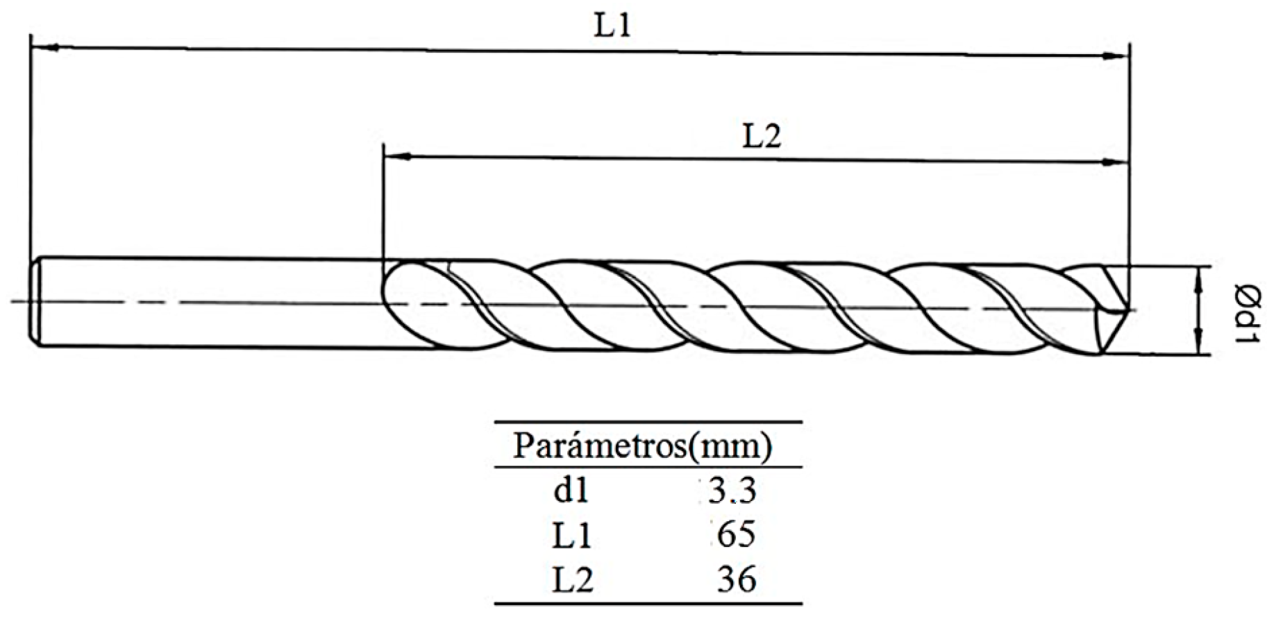
All drilling tests were carried out on a Tongtai TMV510 CNC machining center (Tongtai Machine & Tool Co., Kaohsiung, Taiwan) (Figure 1a) with Fanuc series OI-MC numerical control (Fanuc Iberia, Barcelona, Spain). The cold compressed air (CCA) cooling and MQL-eco lubrication systems were, respectively, CCA equipment (Vortec, Cincinnati, OH, USA) (Figure 1c) and an Accu-Lube with a frequency generator MQL system (Accu-Lube (ITW), GA, Dayton, OH, USA) (Figure 1d) with eco-fluid, which was custom-made and water-based, with polyol esters (Leitat Technological Center, Terrassa, Spain). The CCA system can work at 0.4–0.7 MPa and 280–600 L/min given a flow between −5 °C and −30 °C. The Accu Lube system works at 0.4–1.0 MPa, with flows varying from 4.5 mL/h to 9 mL/h. The surface roughness was measured with an Alicona Infinitive Focus S.L, optics 10× (Bruker Alicona, Graz, Austria) (Figure 1b). The tools used were high-performance Garant HSCO drill bits (Hoffmann GmbH, Munich, Germany) (Figure 2), whose characteristics are given in Table 2. The work material was an Inconel 625 (Böhler, Viladecans (Barcelona), Spain) sheet, commonly used in aeronautical components requiring high-temperature strength and corrosion resistance, with 150 × 25 × 1.5 mm dimensions. Table 3 summarizes all equipment, tools and materials used in the work.

2.2. Experimental Campaign

A statistically designed experimental campaign was conducted to analyze the influence of spindle speed, S, (rpm), feed rate, f, (mm/min), and cooling/lubrication method, R, (MQL-eco and CCA) on surface roughness during the drilling of Inconel 625. The factors and levels used in the experimental design are presented in Table 4, for the analysis of variance (ANOVA), and in Table 5, for the response surface methodology (RSM). For the ANOVA, a full factorial was taken (23). That is, 8 tests are necessary for this type of analysis. However, for the RSM, it is necessary to take two extreme values, above (upper) and below (low) those taken for the ANOVA, and another one in between (medium), which leads to an experimental design with 13 tests, and considering that all tests are repeated, this brings the total to 26.
The spindle speed and feed rate ranges were selected based on the manufacturer’s recommendations for HSS-Co tools with nickel-based alloys and the previous literature on Inconel drilling. These values ensure a representative range of practical industrial conditions while avoiding excessive tool wear or thermal damage.
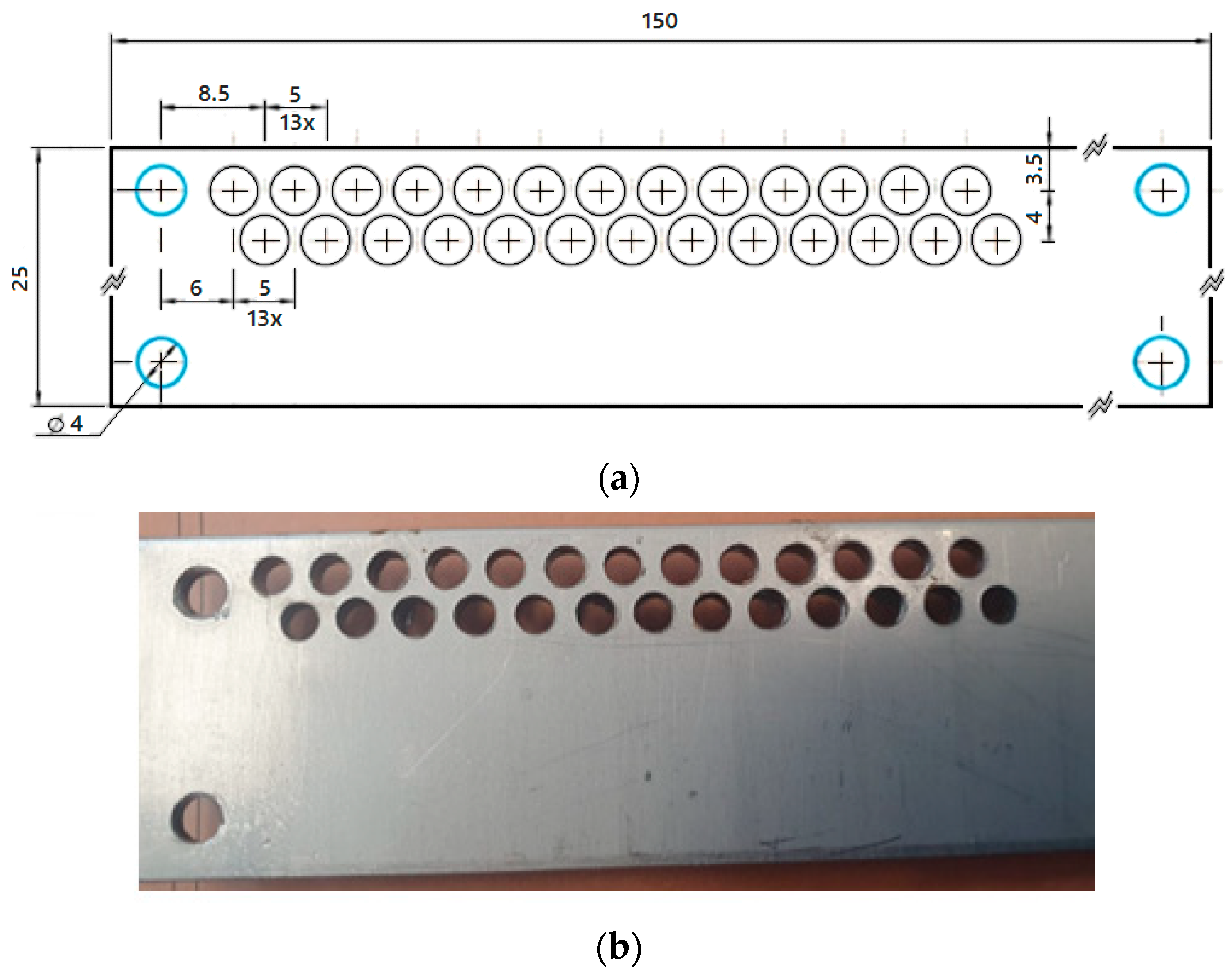
Before carrying out all the tests, the tools, machining center, cooling/lubrication equipment, and specimen were prepared and the cutting parameters were selected. Then, the workpiece was rigidly clamped to a steel fixture to prevent vibration and guarantee perpendicular drilling. Subsequently, the trials were carried out according to pre-planning in a Tongtai TMV510 machining center equipped with a CNC Fanuc system, which was fitted with a CCA system and a Vortec cold air gun at a pressure and flow that provided an air flow with a temperature of −14 °C and a minimum quantity lubricant system, Accu-Lube, with an experimental eco-fluid water-based polyol ester (Figure 1c,d), with a medium flow of 6 mL/h. After each drill’s machining, the holes were cleaned with compressed air before measurement to remove chip and eco-fluid residues (see Figure 3b). Afterwards, machining operations were carried out and, finally, test photographs and videos were taken and recorded for further analysis.

2.3. Surface Roughness Measurement and Data Analysis

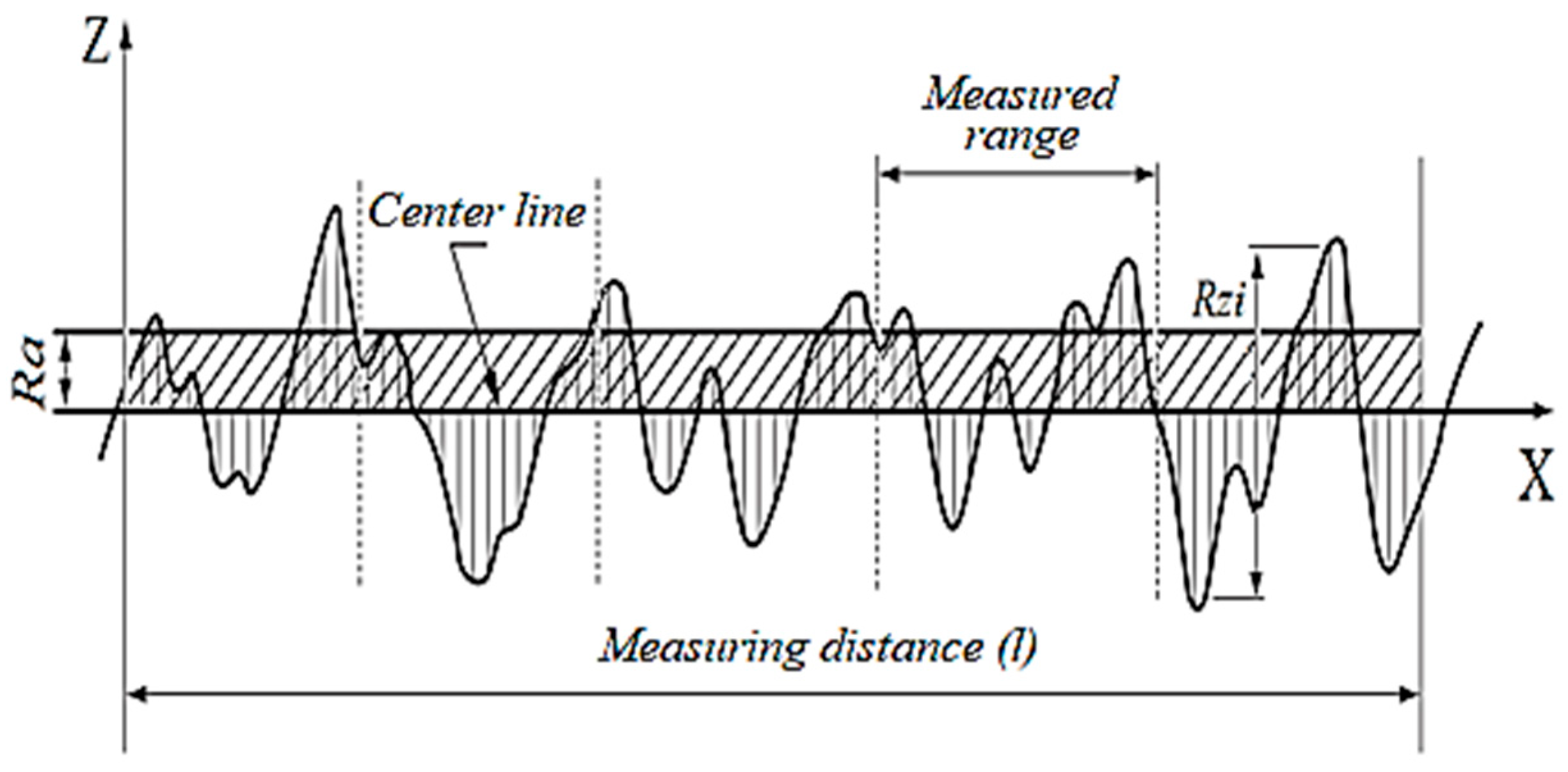
Once the specimen was machined, the holes were cleaned at room temperature and the surface roughness of the drilled holes was measured. In particular, the surface roughness inside each hole was measured using an Alicona Infinitive Focus S.L, optics 10× (Bruker Alicona, Graz, Austria). Measurements were taken on the inside of the hole with a surface area of 2 × 2 mm2. The data obtained were collected using a defined protocol. The response variable selected in this study is the roughness in terms of arithmetical mean roughness, Ra (μm) (Equation (1)), and the average maximum ten-point height, Rz (μm) (Equation (2) (see Figure 4). Concretely, three values of Ra and Rz were taken for each hole.
R a = 1 l   0 l Z ( x ) d x
R z = 1 5 i = 1 5 R z i
Once the data were obtained, a statistical analysis was performed, including an analysis of variance. The variability of the arithmetical mean roughness, Ra (μm), and the average maximum ten-point height of irregularities, Rz (μm), were modeled using ANOVA, identifying the influencing factors and interactions between them. Additionally, in order to explore the relationship between factors and responses, the response surface methodology (RSM) was used.

3. Results and Discussion

3.1. Results

Table 6 shows the relation between the cutting conditions used in each test and the average results (from the three measurements taken) for the Ra and Rz values obtained after machining. An ANOVA was performed, aiming to analyze statistically significant factors affecting the variation in the response variable values Ra and Rz collected during the experiment. In addition, a response surface methodology (RSM) was used for optimization purposes. This technique allows us to model the relationship between variables and responses. Minitab 17.1 software (Minitab LLC, State College, PA, USA) was used to generate the experimental designs for both the ANOVA and RSM.
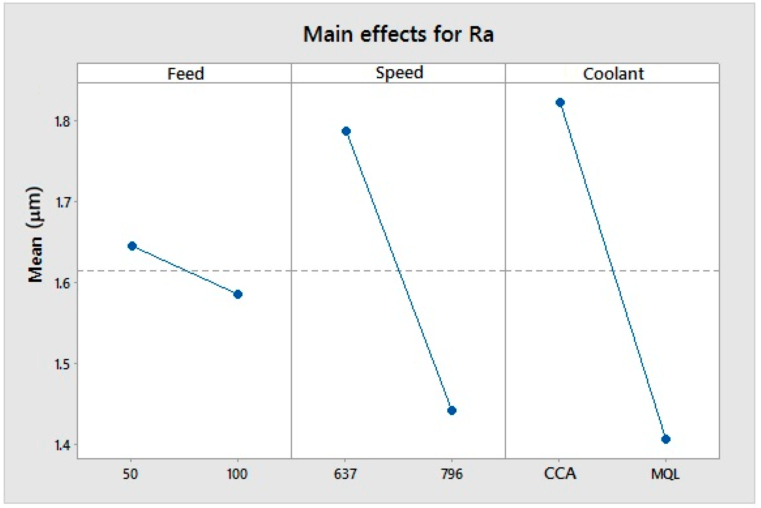
Before carrying out the statistical analysis, the assumption of normality for the average Ra and Rz was checked. After the ANOVA, interactions up to the third order were taken into account, and successive iterations were carried out until all the values were significant. In each iteration, the statistically less significant effect was excluded if it had a p-value greater than 0.05. Taking into account the results, it was concluded that the influencing factors in both cases (Ra and Rz) were the coolant and the interaction between the speed and the coolant. Speed was also statistically significant for Ra. Considering the variability of the surface roughness of the drilled Inconel 625 test probe, explained by the statistically significant effect obtained from the analysis of variance, the percentage of variability attributed to each effect is shown in Table 7. Figure 5 shows the main influencing factors for Ra. The coolant and speed are statistically significant, whereas the feed rate does not have a statistically significant effect. The coolant is the most influential factor in the variability of the surface roughness; its average value is 1.82 µm for CCA and is 1.41 µm for MQL. For the speed factor, at 637 rpm, the average surface roughness is 1.79 µm, and for 796 rpm, it is 1.44 µm.
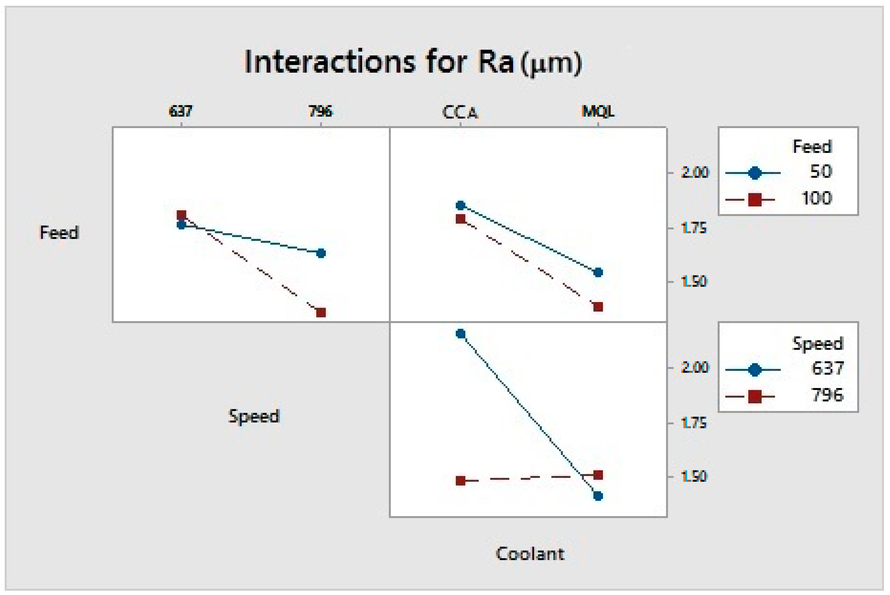
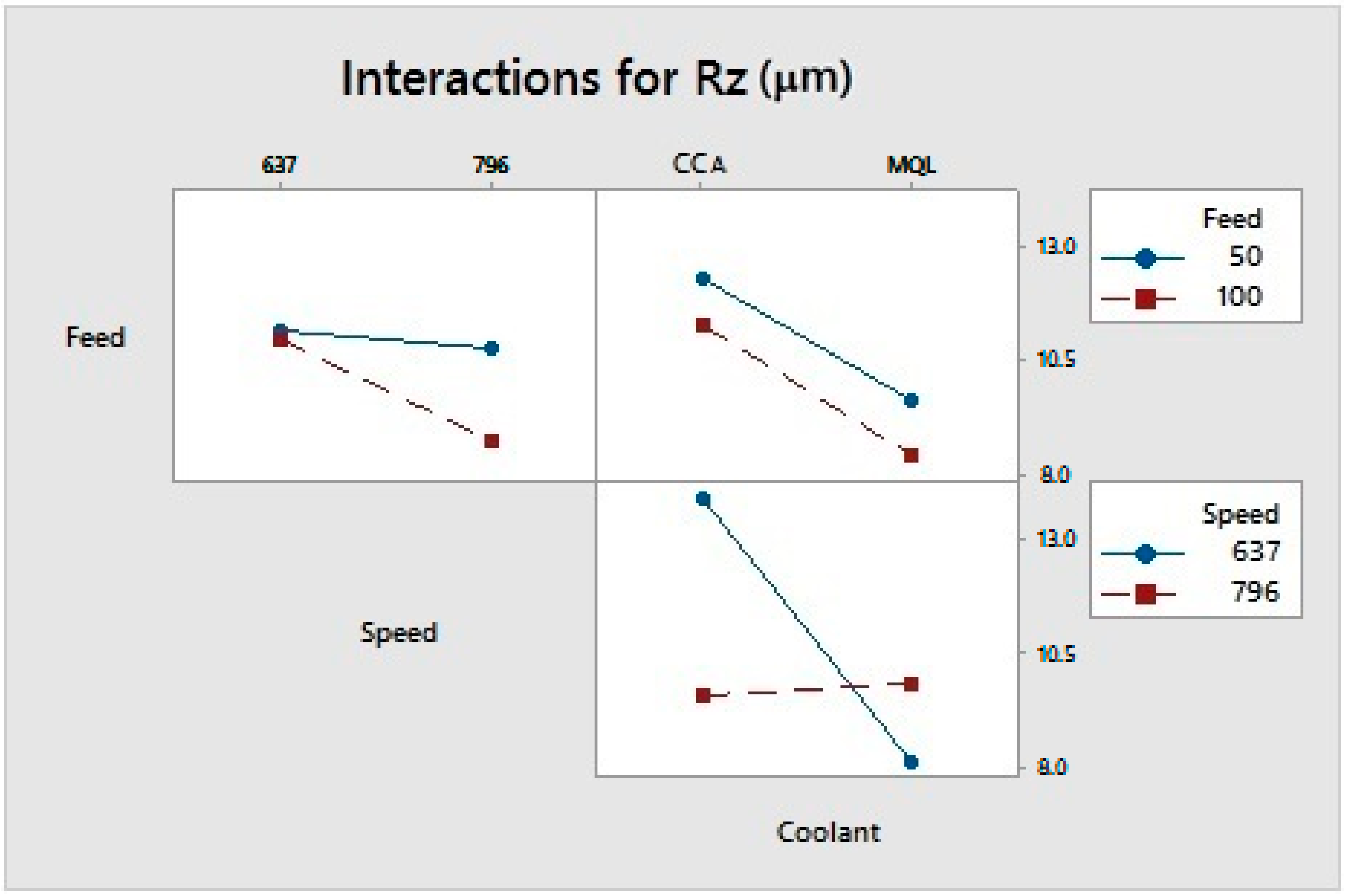
Figure 6 and Figure 7 show the interactions between the main factors for Ra and Rz. In both cases, the only statistically significant interaction is the speed * coolant interaction. The feed * speed and feed * coolant interactions are not statistically significant in the variability of the surface roughness. For Ra, the speed * coolant interaction shows that for 796 rpm, the value of the surface roughness remains almost constant, at 1.48 µm for CCA and 1.51 µm for MQL, while for 637 rpm, the surface roughness varies from 2.17 µm for CCA to 1.41 µm for MQL. For the response variable Rz, the surface roughness remains almost constant at 796 rpm, with values of 9.58 µm for CCA and 9.86 µm for MQL. Meanwhile, the surface roughness at 637 rpm varies from 13.88 µm for CCA to 8.17 µm for MQL.
The speed * coolant interaction for Ra and Rz, as shown in Figure 6 and Figure 7, indicates that MQL is more effective at lower speeds (637 rpm), being more effective for Rz. This result is in agreement with research by Behera et al. [17], which shows that MQL is more effective at slower cutting speeds. This may be due to its greater possibility of penetrating the chip–tool interface. However, when the cutting speed increased, the MQL impact became less important due to the difficulty of efficiently penetrating the chip–tool interface. Prabhat et al. [20] indicate that MQL produces fragmented chips and that the absence of continuous chips and wear in the drilled hole area improves the surface finish.
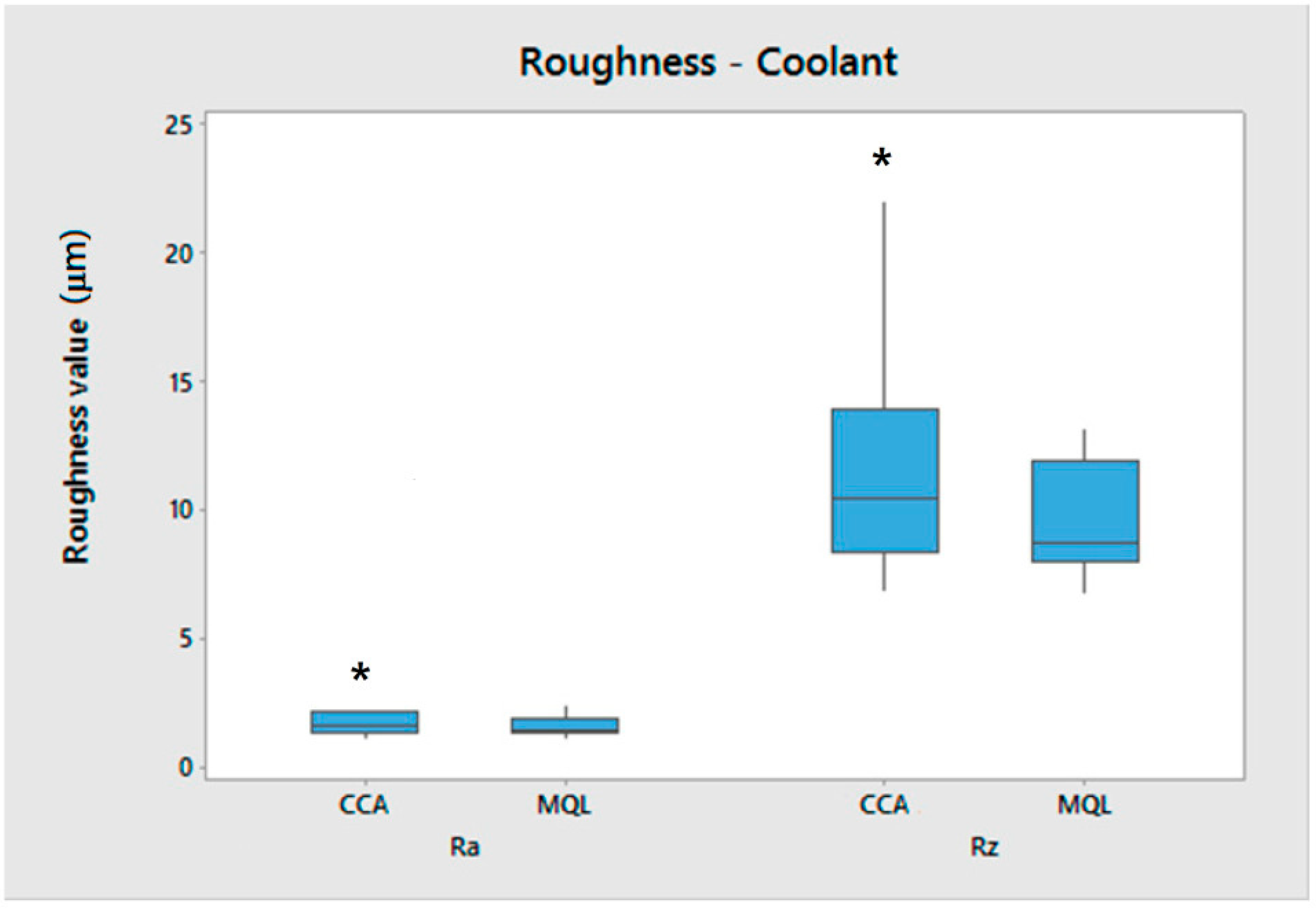
The roughness-coolant relationship is represented in Figure 8. For Ra, the median is 1.59 µm for CCA and 1.47 µm for MQL. The statistical dispersion of the data in terms of the interquartile range (IQR) is 0.755 µm for CCA and 0.565 µm for MQL. For Rz, the median varies from 10.47 µm for CCA to 8.76 µm for MQL. The spread of the data in terms of the IQR varies from 5.505 µm for CCA to 3.923 µm for MQL.
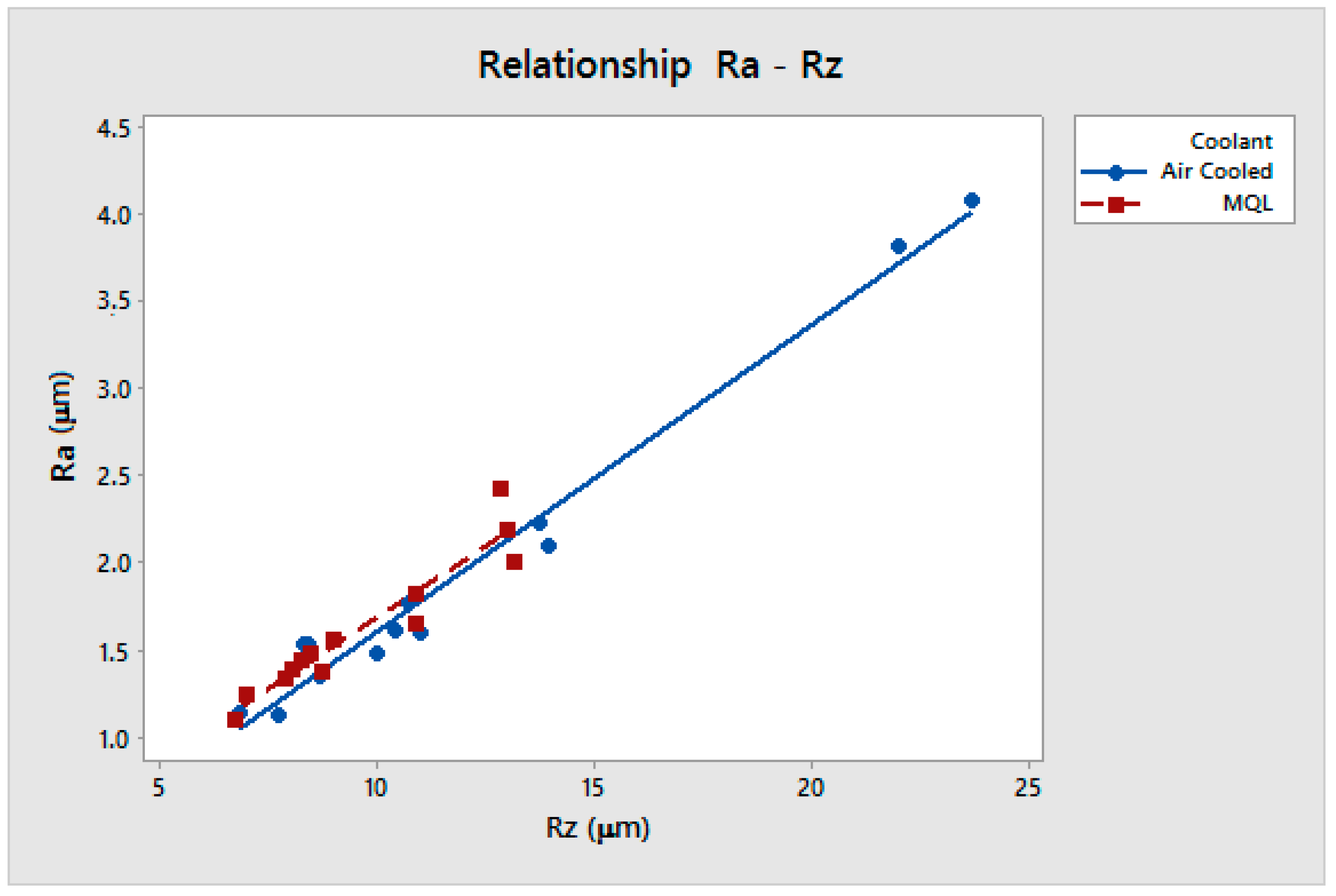
According to the analyses and the interactions and contributions of the different factors, it is possible to establish a relationship between both response variables. The coordinates for the maximum point are Ra = 4.08 µm and Rz = 23.70 µm; for the minimum point, they are Ra = 1.09 µm and Rz = 6.75 µm (Figure 9).
For cold compressed air (CCA),
R a = 0.1715 + 0.1769 R z
For MQL–eco,
R a = 0.0613 + 0.1595 R z
Some investigations associate surface roughness with fatigue resistance [28,29,30]. For example, Xiao et al. [28] demonstrate that the fatigue life–surface roughness curve reflects the relationship between both parameters and its significance for engineering applications. Javadi et al. [31] show that the correlation between roughness and crack paths is confined to large areas in the roughness profile. These large areas have a significant effect on the corrosion resistance. Yiwei et al. [34] show that smoother surface conditions lead to a better pitting resistance. Tolei et al. [32,33] explored this behavior on nickel and attributed it to low roughness promoting the formation of a stable passive film. For rougher surfaces, there is a greater contact area between the corrosive solution and metal-trapped corrosive ions in deep grooves, leading to pitting processes. Dhananjay et al. [35] also demonstrate that corrosion increases with surface roughness due to the increase in the surface area during corrosion. Studying the roughness Ra alone is not the most efficient way to understand the behavior of the machined area with respect to fatigue and corrosion resistance. Studying the roughness Rz is more relevant due to its relationship with the largest peaks and troughs.
In order to explore the relationship between factors and responses, the response surface methodology was used, which can be represented as follows:
γ = φ f ,   S ,   R , R a , R z ± ϵ
where γ is the desired response, φ is the response function, and ϵ is the fitting error. An approximation of γ was performed by using the fitted second-order polynomial mathematical model or quadratic model. This model can be expressed as follows:
γ = β 0 +   i = 1 k β i     x i +   i = 1 k β i i   x i 2 + i < j k β i j   x i   x j   ±   ε
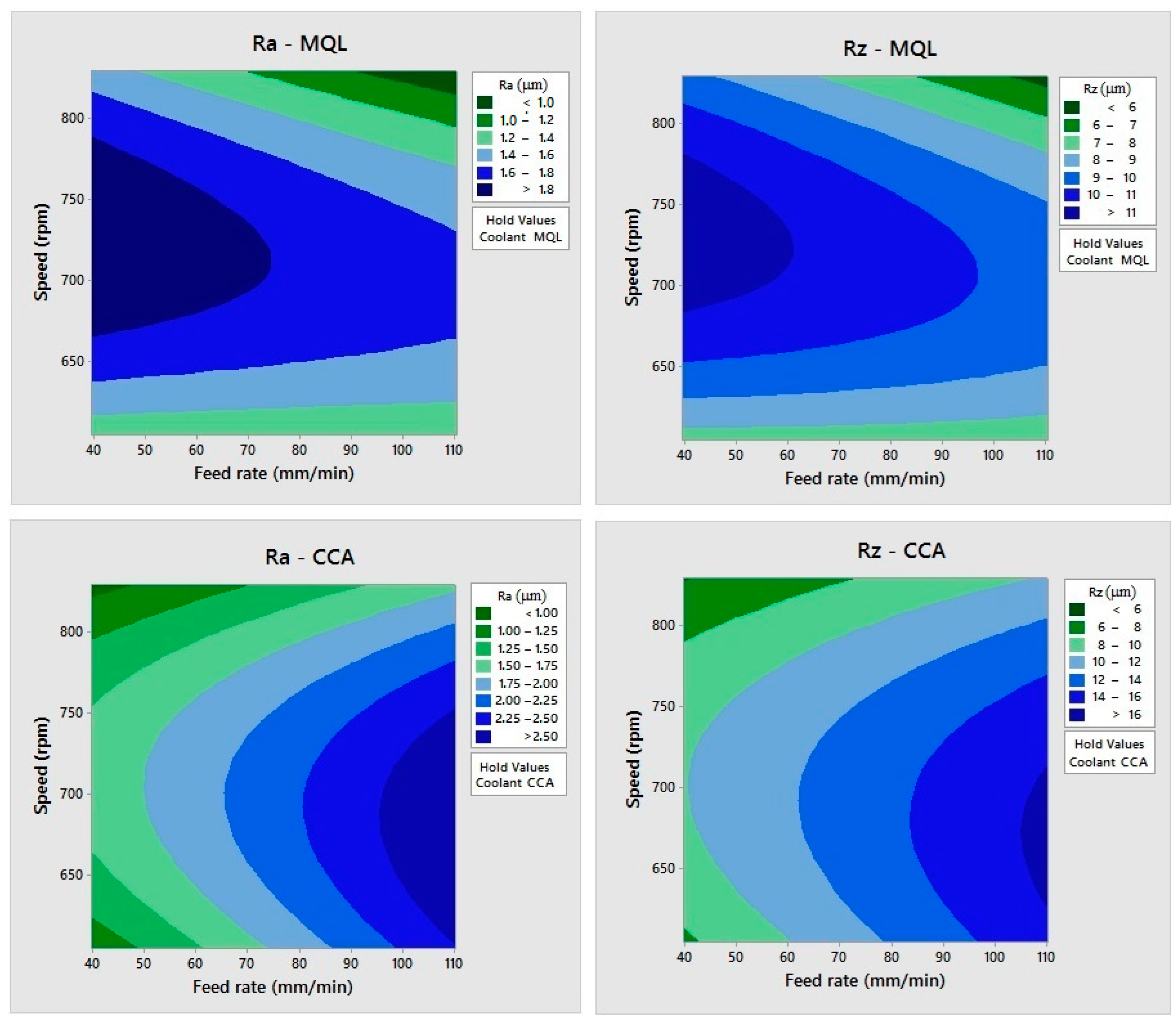
This technique allows us to optimize the best combination of factors to achieve the desired response. Figure 10 represents the response surfaces of all roughness/coolant combinations. The effect of changing the speed and feed rate is studied by keeping the coolant at the MQL and air-cooled (CCA) level. The regions are separated between maximum and minimum surface roughness values. The response surfaces confirmed that a nonlinear and interactive relationship exists for speed and feed rate with surface roughness.
In the case of MQL, for a speed of 716.5 rpm, the worst surface roughness, Ra, is obtained (2.43 µm) for a lower feed rate range (39.64–75 mm/min). For cold compressed air (CCA), the surface roughness, Ra, obtained is 4.08 µm for a higher feed rate range (75–110.35 mm/min). For CCA, taking the feed rate to be constant at 75 mm/min, lower surface roughness values are obtained at lower and higher speeds. For 604.07 rpm, the roughness value is 1.12 µm, and for 828.93 rpm, it is 1.14 µm. For Ra and both types of coolant, traveling horizontally along the response surfaces indicates the significance of speed at lower (604.07 rpm) and higher (828.93 rpm) values and the importance of the feed rate in making the drilling process efficient. The response variable, Rz, shows similar behavior to Ra. For a speed of 716.5 rpm, the worst surface roughness (13.19 µm) is obtained in the lower feed range (39.64–75 mm/min) for MQL, and for CCA, a maximum value of 23.70 µm is obtained in the highest feed range (75–110.35 rpm). Taking a constant feed rate of 75 mm/min for CCA, the best results for surface roughness are obtained: Rz, 7.77 µm at 604.07 rpm and 6.85 µm at 828.93 rpm.
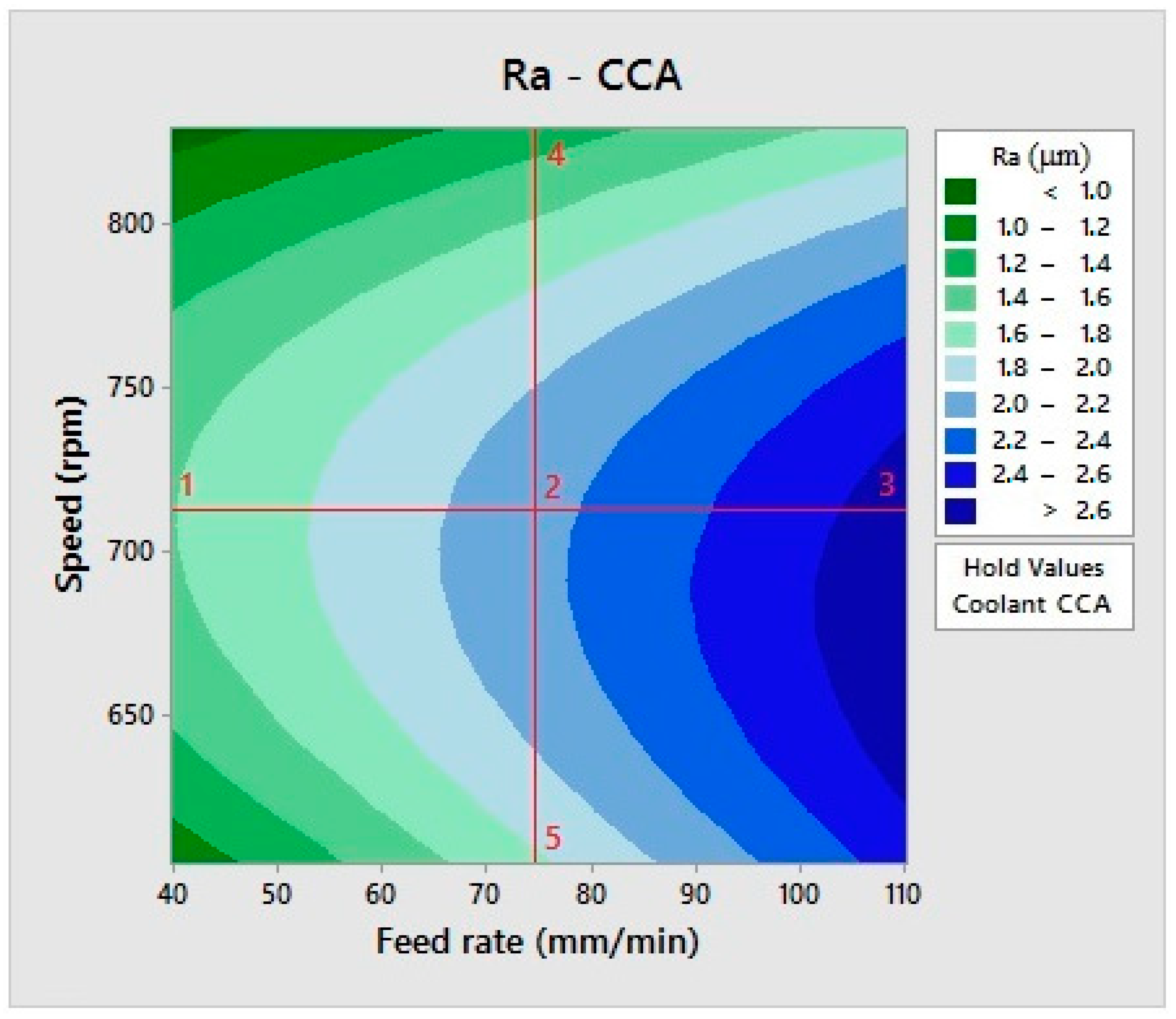
Figure 11 represents the response surfaces for the Ra–cold compressed air (CCA) relationship, relating the cutting speed and feed rate to the surface roughness.
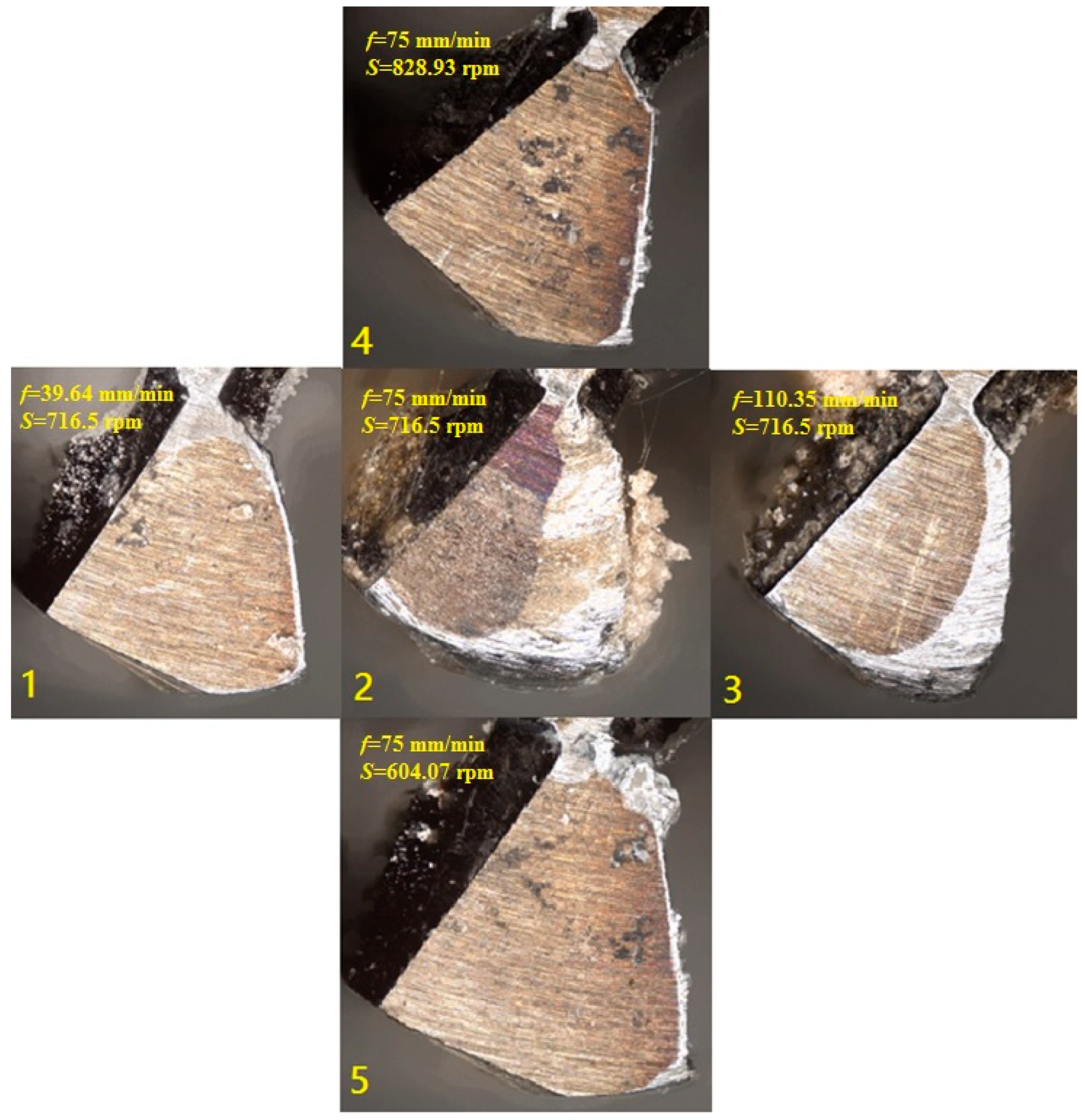
To evaluate the difference in tool life between the maximum and minimum values of cutting speed and feed rate and its relationship with the surface roughness, five points along the x-axis in the range of 700 rpm and along the y-axis in the range of 75 mm/min were taken. The cutting conditions are as follows: for point 1, f = 39.64 mm/min and S = 716.5 rpm; for point 2, f = 75 mm/min and S = 716.5 rpm; for point 3, f = 110.35 mm/min and S = 716.5 rpm; for point 4, f = 75 mm/min and S = 828.93 rpm; and for point 5, f = 75 mm/min and S = 604.07 rpm. Figure 12 shows an image of one flute for each drill bit for the five points selected. It is observed that the tool shows better performance at low (604.07 rpm) or high (828.93 rpm) speed values and low (39.64 mm/min) or medium (75 mm/min) feed rate values from the ranges studied. For medium values of the speed (716.5 rpm), the tool shows the worst performance. The surface roughness expected from the response surface shown in Figure 11 is related to the damage observed on the flute’s cutting edge, as shown in Figure 12. The tool wear observed corresponds to the maximum values of the surface roughness expected.
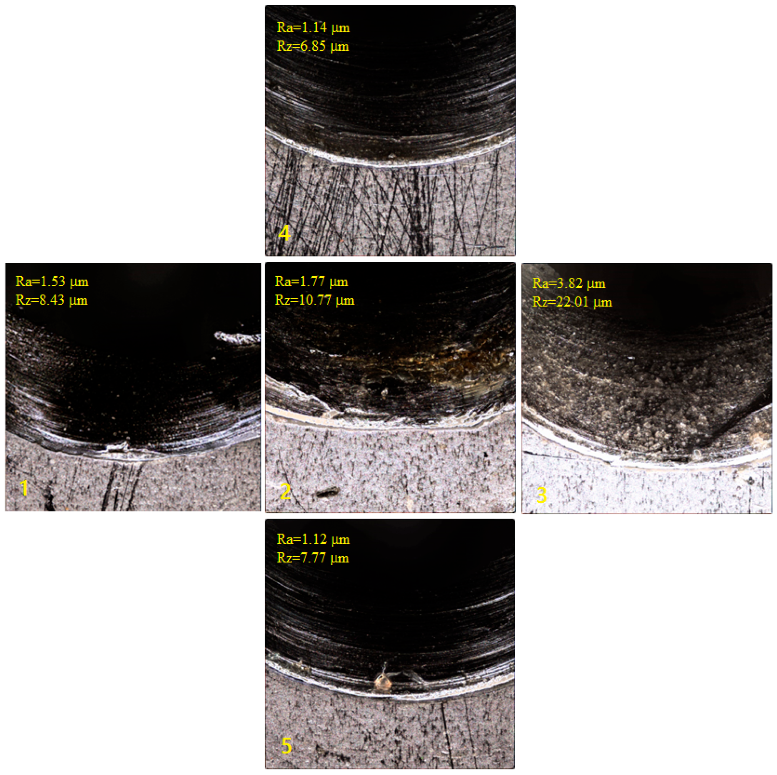
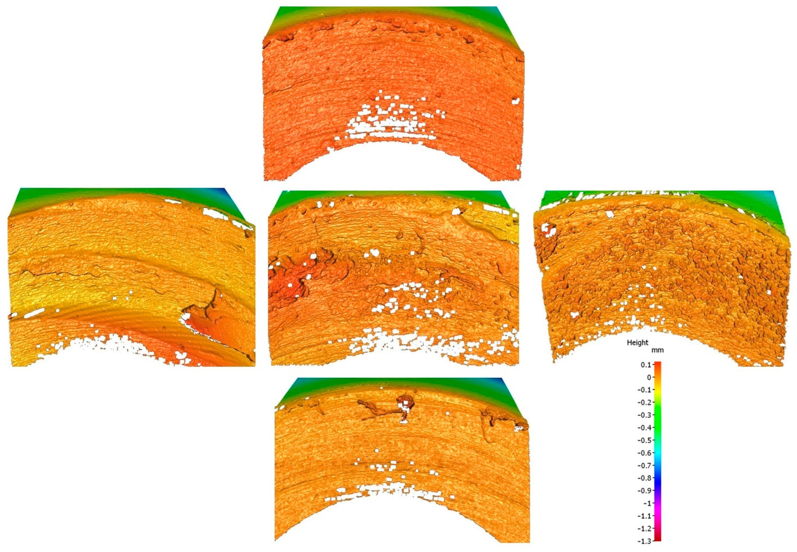
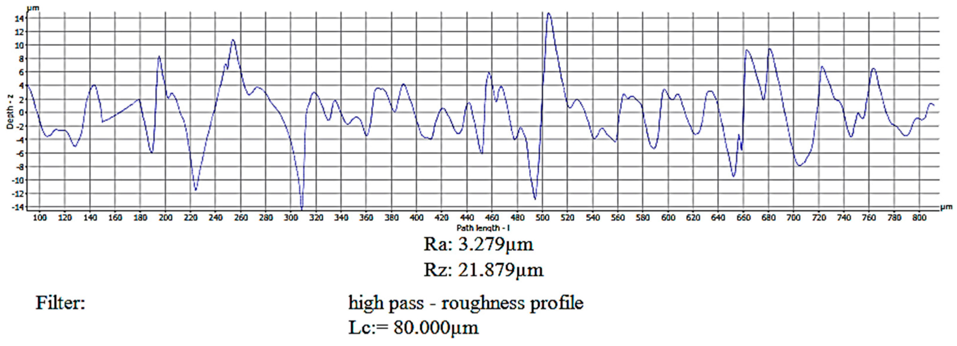
The surface roughness obtained for the five points selected is shown in Figure 13. The values are as follows: for point 1, Ra = 1.53 mm and Rz = 8.43 mm; for point 2, Ra = 1.77 mm and Rz = 10.77 mm; for point 3, Ra = 3.82 mm and Rz = 22.01 mm; for point 4, Ra = 1.14 mm and Rz = 6.85 mm; and for point 5, Ra = 1.12 mm and Rz = 7.77 mm. To obtain these values, a representative area of 2 × 2 mm was scanned for each drilled hole. In each representative area, three measurements were taken and the average value in terms of Ra and Rz was calculated. Figure 14 shows the 3D reconstruction of the scanned area for the holes at the five aforementioned positions. The measurement of Ra and Rz was taken by measuring the 2D profile. Figure 15 shows an example of a 2D profile measurement obtained in the hole at point 3.
The tool wear was not modeled as a separate factor in the ANOVA; nevertheless, as a quick way of obtaining a wear value for the five points selected, it was analyzed in terms of the percentage reduction in the diameter of the flute compared to a new drill bit (d = 1.480 mm). The maximum tool wear at point 3 is 17.97% (d = 1.214 mm) and corresponds to the maximum surface roughness values obtained at that point, Ra= 3.82 mm and Rz = 22.01 mm. At point 2, the tool wear observed is 13.31% (d = 1.283 mm), corresponding to Ra = 1.77 mm and Rz = 10.77 mm. Points 1, 4, and 5 do not show significant wear on the flute’s cutting edge.
The results obtained in this experimental study provide a comprehensive overview of how drilling parameters and cooling strategies influence the surface roughness of Inconel 625 rivet holes. From the descriptive analysis, the Ra values ranged from 1.09 µm to 4.08 µm and the Rz values ranged from 6.75 µm to 23.70 µm, depending on the test conditions. The best results were obtained with MQL at 110.35 mm/min and 716.5 rpm (Ra = 1.09 µm, Rz = 6.75 µm), while the worst results were obtained with CCA at 75 mm/min and 716.5 rpm (Ra = 4.08 µm, Rz = 23.70 µm). Of the 26 tests, 15 conditions (just over half) achieved a surface roughness within the target range required by the aeronautical industry (Ra = 0.8–1.6 µm), with MQL presenting the highest percentage of compliant cases.
The ANOVA confirmed that the most relevant source of variability was the interaction between speed and the coolant, followed by the coolant factor alone and, in the case of Ra, the speed. The feed rate was not statistically significant for either Ra or Rz. These findings highlight that the selection of the optimal parameters should consider the combined effect of speed and the cooling method, rather than treating them as independent variables.
The response surface methodology (RSM) determined nonlinear and interactive behavior: the worst surface roughness values were obtained at 716.5 rpm, but the limiting factor differed depending on the cooling method used. With MQL, the roughness increased at lower feed rates, while with CCA, it worsened at higher feed rates. At higher speeds, both cooling methods tended to reduce the surface roughness, demonstrating that operating at speeds further from the mid-range yields better results.
The correlation analysis between Ra and Rz generated distinct regression models for each coolant method, confirming that while both parameters describe surface roughness, their relationship is influenced by the cooling method. MQL showed lower slopes, indicating more stable results when linking Ra to Rz.
Finally, the tool wear analysis confirmed that higher surface roughness values coincided with more severe wear damage, especially at intermediate speeds (700 rpm). This reinforces the need to optimize cutting conditions not only to minimize surface roughness but also to extend the tool life.
Overall, the results demonstrate that the use of MQL-Eco consistently leads to lower surface roughness values and lower variability compared to CCA, offering a more reliable path to achieving aeronautical industry standards. The practical implication is that sustainable cooling technologies can be successfully implemented in nickel-based alloy machining operations, provided the process parameters are carefully optimized to avoid unfavorable interactions between speed and the coolant.

3.2. Dicussion

After presenting the results and comparing them with those found in the literature on the subject, they will now be discussed according to three themes.

3.2.1. Influence of Cooling/Lubrication Method

The cooling method has a marked effect on the resulting surface roughness. When the minimum quantity lubrication (MQL-Eco) is used, the mean surface roughness is Ra = 1.61 µm and Rz = 9.64 µm. With cold compressed air (CCA), the mean values increase to Ra = 1.95 µm and Rz = 11.99 µm. Therefore, MQL achieves a reduction of, approximately, 17% in Ra and 20% in Rz compared with CCA.
The minimum Ra value obtained under MQL is 1.09 µm, while the maximum reaches 2.43 µm. For CCA, the range extends from 1.12 µm to 4.08 µm, indicating a less stable surface finish. A similar trend is observed for Rz, which varies between 6.75 µm and 13.19 µm under MQL and between 6.85 µm and 23.70 µm under CCA.
These results confirm that the use of lubricant improves process stability and reduces both average roughness and dispersion.
The differences found between MQL and CCA can be attributed to the presence of a thin lubricating film in MQL, which reduces friction and adhesion at the tool–chip interface, thus preventing built-up edge (BUE) formation and the tearing of the machined surface. Conversely, CCA provides effective convective cooling but no tribological protection, resulting in intermittent contact, frictional heating, and higher peak roughness values.
Overall, the MQL-Eco system proves to be the most effective sustainable technique for maintaining surface integrity within aeronautical standards (0.8 µm < Ra < 1.6 µm) while minimizing lubricant consumption and environmental impact.

3.2.2. Influence of Cutting Parameters

The combined effect of spindle speed (S) and feed rate (f) is analyzed in this work through the ANOVA obtained from the factorial design shown in Table 4 and the values presented in Table 6 for those concrete combinations. It can be seen that increasing the feed rate from 50 mm/min to 100 mm/min led to a consistent rise in both Ra and Rz across all cooling conditions. On average, the roughness increases by 35–40%, approximately, when the feed rate doubled, which is attributed to the greater feed per revolution and the corresponding deepening of feed marks on the hole’s surface.
The spindle speed also affects the surface finish, though to a lesser extent. The higher speed (796 rpm) generally produced slightly lower roughness values compared with the lower one (637 rpm), especially for MQL, owing to the improved chip segmentation and reduced contact time per revolution.
The interaction between the feed rate and the cooling method (f × R) is also significant, although the detrimental effect of a high feed rate is partially mitigated when MQL is used due to its superior lubricating ability.
The ANOVA confirms that the feed rate is the dominant parameter, followed by the cooling/lubrication method and the spindle speed.
The response surface model shows that the optimal region of Ra for aeronautic applications (0.8 µm < Ra < 1.6 µm) is achieved at any feed rate and either a very low or very high spindle speed under MQL-Eco conditions and at a low (<50 mm/min) feed rate for any spindle speed value or at a higher spindle speed at any feed rate under CCA conditions.
These findings are consistent with prior studies on Inconel 625 drilling [17,18,19,20,21], reinforcing the notion that lubrication efficiency plays a more decisive role than cutting speed in controlling surface quality when sustainable cooling techniques are applied.

3.2.3. Tool Wear and Surface Integrity Correlation

Although this work does not include quantitative measurements of tool wear, the evolution of Ra and Rz provides indirect information about the surface integrity.
The increase in both parameters, Ra and Rz, with the feed rate, especially under CCA, indicates more aggressive cutting and likely greater tool deterioration.
Under MQL, the smaller variation in Ra and Rz suggests more stable cutting conditions, consistent with the reduced friction and temperature at the tool–chip interface.
Thus, although no wear values were measured, the roughness trends imply that surface integrity was better preserved under MQL-Eco than under CCA.

3.3. Novelty and Contribution of the Study

The innovative nature of this experimental study lies in its integrative approach to the machining performance, sustainability, and structural reliability of aeronautical components. While previous studies have separately examined the effects of drilling parameters on hole quality [4,11,22] or the benefits of sustainable cooling methods in machining [6,12], few studies have systematically addressed the combined influence of feed rate, spindle speed, and environmentally friendly cooling strategies when drilling nickel-based alloys. Nickel-based alloys and Inconel 625, in particular, represent a critical challenge in aerospace applications due to their low machinability despite their excellent mechanical and chemical properties [9,10].
A significant advancement of this experimental study is the comparative evaluation of minimum quantity lubrication with an eco-friendly fluid (MQL-Eco) and cold compressed air (CCA) for drilling rivet holes in Inconel 625. Using an analysis of variance (ANOVA) and response surface methodology (RSM), this study not only identifies the speed*coolant interaction as the dominant factor influencing surface roughness but also develops predictive relationships between Ra and Rz under sustainable cooling conditions. This dual approach, both statistical and experimental, offers a more comprehensive understanding than traditional parametric analyses, which typically limit their scope to Ra values or tool wear.
Furthermore, while the previous literature has established the role of surface roughness in fatigue crack initiation [28,29,30,31] and corrosion resistance [32,33,34,35], the present experimental study demonstrates that sustainable cooling technologies can consistently achieve surface roughness values within aeronautical standards (0.8–1.6 µm). This finding links the gap between environmental responsibility and stringent industry requirements, demonstrating that sustainable practices can be adopted without compromising structural reliability.
In general, this experimental study contributes both methodologically and practically relevant insights: methodologically, by integrating an experimental design with statistical optimization tools, and practically, by providing the aerospace industry with viable ways to adopt greener manufacturing technologies that meet critical surface integrity requirements.

4. Conclusions and Future Research

This experimental study aimed to analyze the influence of sustainable drilling strategies for rivet hole formation in nickel-based alloys for aeronautical applications. In particular, besides the cutting conditions, the effect of the sustainable cooling/lubrication technologies employed was examined. In this case, minimum quantity lubrication was compared with an eco-fluid (MQL-Eco) and cold compressed air (CCA). The optimization of the cutting conditions and the degradation of the drill bit after a single use were studied using surface roughness (Ra and Rz) as a response variable. The results highlight that the interaction between the spindle speed and the coolant and the individual coolant and spindle speed factors were statistically significant in the ANOVA.
The spindle speed * coolant interaction was the main cause of variability in both roughness variables.
The coolant factor was the second most significant cause of variability in both roughness variables, with the MQL method showing the best results.
The spindle speed factor was statistically significant in the variability of Ra, but it was not statistically significant in the variability of Rz. In particular, the spindle speed showed nonlinear behavior, with the worst surface finish appearing at an intermediate speed (≈716 rpm) and the best at either low or high speeds, indicating that thermal and dynamic effects interact with lubrication efficiency.
The feed rate factor was not statistically significant in the variability of any surface roughness variable analyzed. However, although the main effect of feed rate was not statistically significant within the studied range, the experimental data revealed a clear tendency for both Ra and Rz to increase when the feed rate was raised from 50 to 100 mm/min, particularly under CCA conditions. This suggests that the mechanical load per revolution amplifies roughness when the lubrication is insufficient.
Minimum quantity lubrication with an eco-friendly fluid (MQL-Eco) consistently produced lower and more stable surface roughness values than cold compressed air (CCA). The mean roughness decreased from Ra = 1.95 µm and Rz = 11.99 µm under CCA to Ra = 1.61 µm and Rz = 9.64 µm under MQL, corresponding to average reductions of approximately 17% and 20%, respectively.
On the other hand, the visual inspection of the tools confirmed that higher roughness values were associated with greater edge wear, while MQL reduced wear progression and maintained surface integrity. Overall, the results confirm that MQL-Eco provides a technically and environmentally viable solution for drilling Inconel 625, achieving surface quality within the aeronautical range requirement (0.8 µm < Ra < 1.6 µm) while minimizing variability and tool degradation.
Additionally, this study showed that the roughness Ra alone is not the most efficient way to understand the behavior of a machined area with respect to fatigue and corrosion resistance. Studying the roughness Rz is more relevant due to its relationship with the largest peaks and troughs.
Future research should expand the scope of the present work by integrating additional aspects of surface integrity beyond roughness. While this study focused on Ra and Rz as key indicators, burr formation is also recognized as a critical factor in hole quality for the aerospace industry; however, its size and morphology were not quantified here. Similarly, roundness and cylindricity are fundamental geometric tolerances that affect hole performance, but they were not experimentally measured in this experimental study. In parallel, recent work on laser drilling of Inconel 625 showed that, due to the heat generated on the surface during the manufacturing process, local hardness variations can reach up to 30% depending on the process conditions, although a direct relationship with surface roughness was not established. Based on this knowledge, future studies should combine measurements of burr, roundness, cylindricity, hardness distribution, and tool wear with roughness analysis to achieve a more comprehensive evaluation of rivet hole integrity in nickel-based alloys and to better correlate machining conditions with in-service performance.

Author Contributions

Conceptualization, J.M.S.d.P. and E.M.R.; methodology, J.M.S.d.P.; software, J.M.S.d.P.; validation, J.M.S.d.P. and E.M.R.; formal analysis, J.M.S.d.P.; investigation, J.M.S.d.P.; resources, J.M.S.d.P., A.G.-D., J.C. and E.M.R.; data curation, J.M.S.d.P., A.G.-D., J.C. and E.M.R.; writing—original draft preparation, J.M.S.d.P.; writing—review and editing, J.M.S.d.P., A.G.-D., J.C. and E.M.R.; visualization, J.M.S.d.P.; supervision, E.M.R.; project administration, A.G.-D., J.C. and E.M.R. All authors have read and agreed to the published version of the manuscript.

Funding

This research received no external funding.

Data Availability Statement

The original contributions presented in this study are included in the article. Further inquiries can be directed to the corresponding author.

Acknowledgments

The authors are grateful for the support of the Industrial Production and Manufacturing Engineering (IPME) Research Group, the Innovation and Teaching Group for Industrial Technologies in Productive Environments (TIA Plus UNED), and the Master of Manufacturing Advanced Engineering.

Conflicts of Interest

The authors declare no conflicts of interest.

References

  1. de Castro, P.M.S.T.; de Matos, P.F.P.; Moreira, P.M.G.P.; da Silva, L.F.M. An overview on fatigue analysis of aeronautical structural details: Open hole, single rivet lap-joint, and lap-joint panel. Mater. Sci. Eng. A 2007, 468–470, 144–157. [Google Scholar] [CrossRef]
  2. Basak, A.K.; Bajwa, D.S.; Pramanik, A. Fatigue Behaviour of Mechanical Joints: A Review. Metals 2025, 15, 25. [Google Scholar] [CrossRef]
  3. Deng, G.; Nagamoto, K.; Nakano, Y.; Nakanishi, T. Evaluation of the Effect of Surface Roughness on Crack Initiation Life. In Proceedings of the 12th International Conference on Fracture, Ottawa, ON, Canada, 12–17 July 2009. [Google Scholar]
  4. Ralph, W.C.; Johnson, W.S.; Toivonen, P.; Makeev, A.; Newman, J.C., Jr. Effect of various aircraft production drilling procedures on hole quality. Int. J. Fatigue 2006, 28, 943–950. [Google Scholar] [CrossRef]
  5. Moreira, P.M.G.P.; De Matos, P.F.P.; Camanho, P.P.; Pastrama, S.D.; de Castro, P.M.S.T. Stress intensity factor and load transfer analysis of a cracked riveted lap joint. Mater. Des. 2007, 28, 1263–1270. [Google Scholar] [CrossRef]
  6. Aamir, M.; Giasin, K.; Tolouei-Rad, M.; Vafadar, A. A review: Drilling performance and hole quality of aluminium alloys for aerospace applications. J. Mater. Res. Technol. 2020, 9, 12484–12500. [Google Scholar] [CrossRef]
  7. Shishkin, S.V.; Shishkin, S.S. The application of rivets with shape memory in aeronautical engineering. J. Mach. Manuf. Reliab. 2010, 39, 179–184. [Google Scholar] [CrossRef]
  8. Viganò, F.; Manes, A.; Giglio, M. Effect of cold driving process on fatigue life of helicopter fuselage joints. Procedia Eng. 2010, 2, 639–647. [Google Scholar] [CrossRef]
  9. Olufayo, O.A.; Boulaares, M.D.; Songmene, V. Machining/machinability of Rene 65 superalloy for aerospace applications. In Proceedings of the 2020 IEEE 11th International Conference on Mechanical and Intelligent Manufacturing Technologies, Cape Town, South Africa, 20–22 January 2020. [Google Scholar] [CrossRef]
  10. Shahwaz, M.; Nath, P.; Sen, I. A critical review on the microstructure and mechanical properties correlation of additively manufactured nickel-based superalloys. J. Alloys Compd. 2022, 907, 164530. [Google Scholar] [CrossRef]
  11. Kilickap, E.; Huseyinoglu, M.; Yardimeden, A. Optimization of drilling parameters on surface roughness in drilling of AISI 1045 using response surface methodology and genetic algorithm. Int. J. Adv. Manuf. Technol. 2011, 52, 79–88. [Google Scholar] [CrossRef]
  12. Aamir, M.; Tolouei-Rad, M.; Giasin, K.; Vafadar, A.; Koklu, U.; Keeble, W. Evaluation of the Surface Defects and Dimensional Tolerances in Multi-Hole Drilling of AA5083, AA6061, and AA2024. Appl. Sci. 2021, 11, 4285. [Google Scholar] [CrossRef]
  13. Doğan, M.A.; Yazman, Ş.; Gemi, L.; Yildiz, M.; Yapici, A. A review on drilling of FML stacks with conventional and unconventional processing methods under different conditions. Compos. Struct. 2022, 297, 115913. [Google Scholar] [CrossRef]
  14. Meng, G.; Gong, Y.; Zhang, J.; Ren, Q.; Zhao, J. Microstructure effect on the machinability behavior of additive and conventionally manufactured Inconel 718 alloys. J. Mater. Process. Technol. 2024, 324, 118228. [Google Scholar] [CrossRef]
  15. Pedroso, A.F.V.; Sebbe, N.P.V.; Costa, R.D.F.S.; Barbosa, M.L.S.; Sales-Contini, R.C.M.; Silva, F.J.G.; Campilho, R.D.S.G.; de Jesus, A.M.P. INCONEL® Alloy Machining and Tool Wear Finite Element Analysis Assessment: An Extended Review. J. Manuf. Mater. Process. 2024, 8, 37. [Google Scholar] [CrossRef]
  16. Khanna, N.; Agrawal, C.; Gupta, M.K.; Song, Q. Tool wear and hole quality evaluation in cryogenic Drilling of Inconel 718 superalloy. Tribol. Int. 2020, 143, 106084. [Google Scholar] [CrossRef]
  17. Behera, B.C.; Mohamed, A.; Muduli, K. Eco-Friendly Machining of Ni-Based Superalloy with High-Velocity Mist Nozzle. Eng. Proc. 2024, 66, 33. [Google Scholar] [CrossRef]
  18. Fernández, D.; Sandá, A.; Bengoetxea, I. Cryogenic Milling: Study of the Effect of CO2 Cooling on Tool Wear When Machining Inconel 718, Grade EA1N Steel and Gamma TiAl. Lubricants 2019, 7, 10. [Google Scholar] [CrossRef]
  19. Safie, N.S.S.; Murad, M.N.; Lih, T.C.; Azmi, A.I.; Wan Hamzah, W.A.; Danish, M. Roles of Eco-Friendly Non-Edible Vegetable Oils in Drilling Inconel 718 through Minimum Quantity Lubrication. Lubricants 2022, 10, 211. [Google Scholar] [CrossRef]
  20. Ranjan, P.; Singh, A.K.; Mujumdar, S. Drilling performance investigation and economic analysis with minimum quantity lubrication (MQL). Manuf. Lett. 2025, 44, 1758–1764. [Google Scholar] [CrossRef]
  21. Khanna, N.; Patel, D.; Raval, P.; Airao, J.; Badheka, V.; Rashid, R.A.R. Comparison of sustainable cooling/lubrication strategies for drilling of wire arc additively manufactured Inconel 625. Tribol. Int. 2024, 200, 110068. [Google Scholar] [CrossRef]
  22. Blanco, D.; Rubio, E.M.; Marín, M.; de Pipaón, J.M.S. A comparative study of tool degradation in the re-drilling of magnesium-based multi-materials through sustainable cooling technologies. Procedia CIRP 2023, 118, 390–395. [Google Scholar] [CrossRef]
  23. Manikandan, M.; Arun, S.; Kuriachen, B.; Mathew, J. Comparative study of micro-die sink and micro-EDM drilled holes for electrode wear and surface roughness. Mater. Today Proc. 2023, in press. [Google Scholar] [CrossRef]
  24. Gobikrishnan, U.; Suresh, P.; Kumaravel, P. Drilling investigations on Inconel alloy 625 material of material removal rate using micro electrochemical machining. Mater. Today Proc. 2021, 37, 1629–1633. [Google Scholar] [CrossRef]
  25. Murali, B.; Karthikeyan, S.; Mohamed, M.J.S.; Manjula, A.; Pandiarajan, P. Improvement of micro-EDM drilling efficiency on Inconel 625. Mater. Today Proc. 2023, in press. [Google Scholar] [CrossRef]
  26. Rajesh, S.; Prabu, D.A.; Gobikrishnan, U.; Kumar, P.J.L.; Selvan, T.A.; Ramesh, A.; Madhankumar, S. Surface roughness assessments and comparative study of Inconel 625 and Inconel 718 alloys after micro electrochemical machining. Mater. Today Proc. 2022, 62, 938–943. [Google Scholar] [CrossRef]
  27. Szwajka, K.; Zielińska-Szwajka, J.; Żaba, K.; Trzepieciński, T. An Investigation of the Sequential Micro-Laser Drilling and Conventional Re-Drilling of Angled Holes in an Inconel 625 Ni-Based Alloy. Lubricants 2023, 11, 384. [Google Scholar] [CrossRef]
  28. Xiao, W.L.; Chen, H.B.; Yin, Y. Effects of Surface Roughness on the Fatigue Life of Alloy Steel. Key Eng. Mater. 2013, 525–526, 417–420. [Google Scholar] [CrossRef]
  29. Alang, N.A.; Razak, N.A.; Miskam, A.K. Effect of Surface Roughness on Fatigue Life of Notched Carbon Steel. Int. J. Eng. Technol. 2011, 11, 160–163. [Google Scholar]
  30. Rao, J.H.; Zhang, K.; Rometsch, P.; Huang, A.; Wu, X. The Influence of Surface Roughness on the Fatigue Performance of Selective Laser Melted Aluminium Alloy A357. In Proceedings of the 16th International Aluminum Alloys Conference (ICAA16) 2018, Montreal, QC, Canada, 17–21 June 2018; Canadian Institute of Mining, Metallurgy and Petroleum: Westmount, QC, Canada, 2018. [Google Scholar]
  31. Javadi, H.; Jomaa, W.; Texier, D.; Brochu, M.; Bocher, P. Surface Roughness Effects on the Fatigue Behavior of As-Machined Inconel718. Solid State Phenom. 2016, 258, 306–309. [Google Scholar] [CrossRef]
  32. Toloei, A.; Stoilov, V.; Northwood, D. Simultaneous effect of surface roughness and passivity on corrosion resistance of metals. WIT Trans. Eng. Sci. 2015, 90, 355–367. [Google Scholar] [CrossRef]
  33. Toloei, A.S.; Stoilov, V.; Northwood, D.O. The effect of different surface topographies on the corrosion behaviour of nickel. WIT Trans. Eng. Sci. 2013, 77, 193–204. [Google Scholar] [CrossRef]
  34. Tang, Y.; Dai, N.; Wu, J.; Jiang, Y.; Li, J. Investigation of Influence of Surface Roughness on Pitting Corrosion of Duplex Stainless Steel 2205 using Various Electrochemical Techniques. Int. J. Electrochem. Sci. 2019, 14, 6790–6813. [Google Scholar] [CrossRef]
  35. Pradhan, D.; Mahobia, G.S.; Chattopadhyay, K.; Singh, V. Effect of surface roughness on corrosion behavior of the superalloy IN718 in simulated marine environment. J. Alloys Compd. 2018, 740, 250–263. [Google Scholar] [CrossRef]
  36. Makhesana, M.A.; Patel, K.M.; Krolczyk, G.M.; Danish, M.; Singla, A.K.; Khanna, N. Influence of MoS2 and graphite-reinforced nanofluid-MQL on surface roughness, tool wear, cutting temperature and microhardness in machining of Inconel 625. CIRP J. Manuf. Sci. Technol. 2023, 41, 225–238. [Google Scholar] [CrossRef]
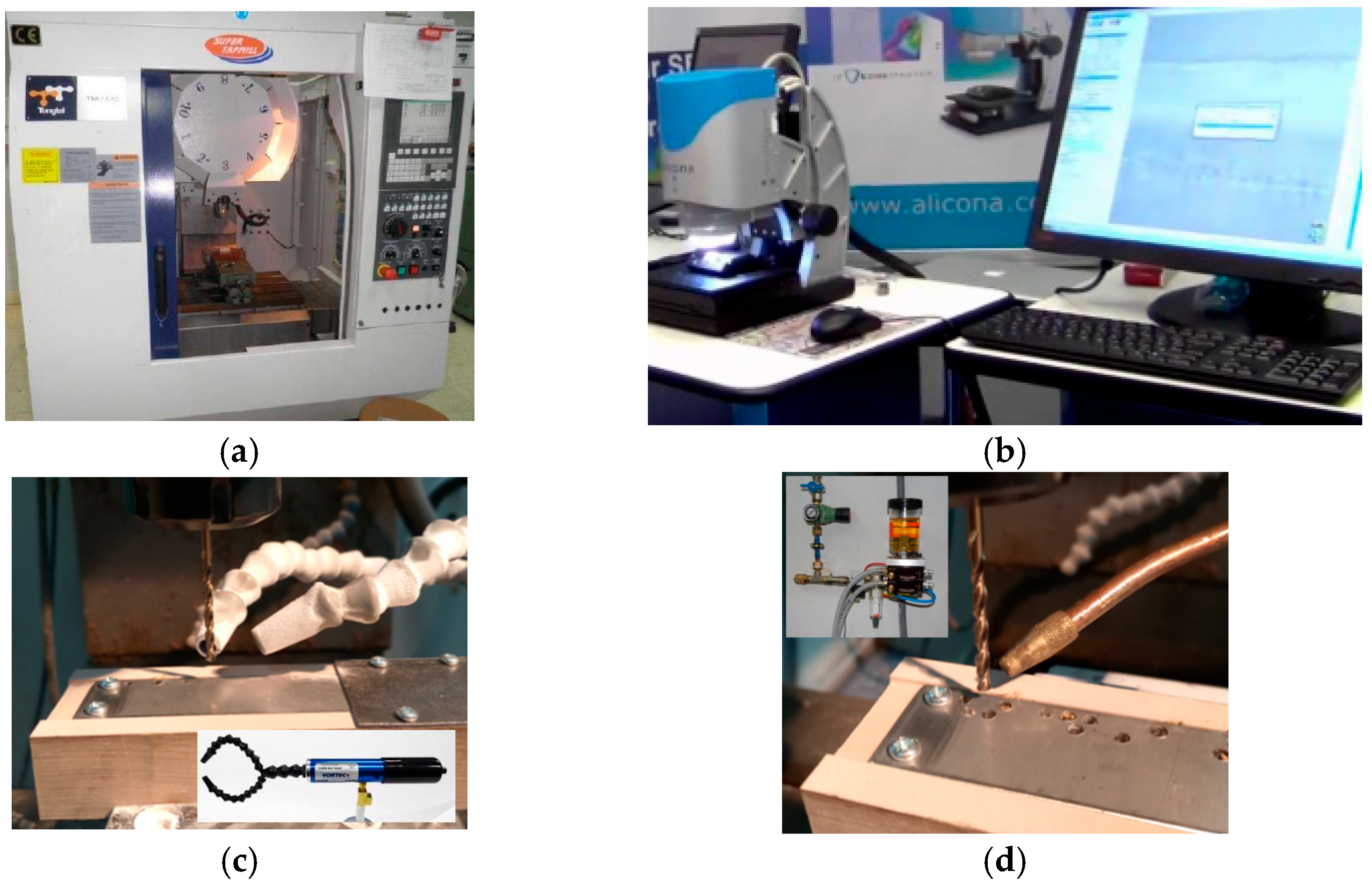
Figure 1. Main equipment used in tests: (a) Tongtai TMV510 CNC machining center; (b) Alicona Infinitive Focus S.L, optics 10×; (c) cold compressed air vortex cooling system; and (d) Accu-Lube with frequency generator for MQL-Eco system.
Jmmp 09 00389 g001
Figure 2. Drill bit dimensions.
Jmmp 09 00389 g002
Figure 3. (a) Layout of the design of experiments in the test tube; (b) test specimen after drilling.
Jmmp 09 00389 g003
Figure 4. Roughness profile definitions.
Jmmp 09 00389 g004
Figure 5. Main factors affecting Ra and Rz.
Jmmp 09 00389 g005
Figure 6. Interactions for Ra.
Jmmp 09 00389 g006
Figure 7. Interactions for Rz.
Jmmp 09 00389 g007
Figure 8. Roughness–coolant relationship. Values marked with an asterisk (*) are outliers. They represent results that are far removed from most values obtained in the trials.
Jmmp 09 00389 g008
Figure 9. Ra–Rz relationship, taking into account the coolant.
Jmmp 09 00389 g009
Figure 10. Response surface for each roughness–coolant combination.
Jmmp 09 00389 g010
Figure 11. Response surface for each Ra–CCA combination (cold compressed air).
Jmmp 09 00389 g011
Figure 12. Tool wear based on cutting conditions. Where the cutting conditions are: (1) f = 39.64 mm/min and S = 716.5 rpm; (2) f = 75 mm/min and S = 604.07 rpm; (3) f = 110.35 mm/min and S = 716.5 rpm; (4) f = 75 mm/min and S = 828.93 rpm; and (5) f = 75 mm/min and S = 604.07 rpm
Jmmp 09 00389 g012
Figure 13. Hole topography and surface roughness obtained for every point selected. Where: (1) Ra = 1.53 μm and Rz = 8.43 μm; (2) Ra = 1.77 μm and Rz = 10.77 μm; (3) Ra = 3.82 μm and Rz = 22.01 μm; (4) Ra = 1.14 μm and Rz = 6.85 μm; and (5) Ra = 1.12 μm and Rz = 7.77 μm.
Jmmp 09 00389 g013
Figure 14. Three-dimensional reconstruction for every point selected.
Jmmp 09 00389 g014
Figure 15. Example of 2D profile obtained.
Jmmp 09 00389 g015
Table 1. Summary of previous studies on sustainable drilling and machining of nickel-based alloys and contribution of this work.
ReferenceMaterial/ProcessCooling/Lubrication StrategyMain ContributionIdentified Limitation/Research Gap
[13,14,15,16]Inconel 718/625—conventional drilling and turningConventional flood coolingReported severe tool wear, high cutting temperatures, and difficulty maintaining surface integrity.Did not explore eco-friendly lubrication or combined factor effects.
[23,24,25,26]Inconel 625—unconventional drilling (EDM, ECM, micro-EDM)No external lubricationImproved MRR and surface precision at micro-scale.Processes unsuitable for industrial rivet-hole drilling; lack of sustainability evaluation.
[27]Inconel 625—drillingConventional lubricationExamined hardness variation in the heat-affected zone.Did not link hardness changes with surface roughness or tool wear.
[17,18,19,20,21]Nickel-based alloys—machining under MQL, CCA, or cryogenic conditionsMQL, cryogenic CO2, or cold airDemonstrated lower temperatures and reduced wear compared to flood cooling.Most studies evaluate one cooling method or a single cutting parameter.
[36]Inconel 625—drilling with nanofluid MQLMQL with nanoparticlesReported up to 40% cost savings and improved roughness.Focused only on economic evaluation; limited statistical modeling.
[6,12,22]Aluminum and hybrid materials—multi-hole drillingSustainable lubrication and air coolingAchieved good surface quality while reducing environmental impact.Results not transferable to Ni-based alloys due to different thermal behavior.
[28,29,30,31,32,33,34,35]Nickel and steel alloys—surface roughness vs. fatigue/corrosionVarious machining conditionsDemonstrated that surface roughness influences fatigue crack initiation and corrosion rate.Did not relate roughness to machining parameters or sustainable cooling.
— (This work)Inconel 625—sustainable drilling for rivet holesMQL-Eco and CCAAddressed the study of the combined influence, on Ra and Rz, of feed rate, spindle speed, and environmentally friendly cooling/lubrication strategies, MQL-Eco and CCA, when drilling Inconel 625; using ANOVA and RMS statistical analysis.
Table 2. Drill bit characteristics.
Diameter3.3 mm
MaterialHSS–Co–TiN (twist drill)
Helix angle37°
Point angle135°
Table 3. Equipment, tools, and materials employed in the tests.
EquipmentSupplierDescription
Machining centerTongtai Machine, Kaohsiung, Taiwan.Tongtai TMV510.
Numerical controlFanuc Iberia, Barcelona, Spain.Fanuc series OI-MC.
MQL-EcoAccu-Lube (ITW), GA, USA.Accu-Lube with frequency generator MQL-eco system.
CCAVortec, Cincinati, OH, USA.Cold compressed air vortex cooling system.
Surface 3D scanBruker Alicona, Graz, Austria.Alicona Infinitive Focus S.L, optics 10×.
ToolsSupplierDescription
Drill bitsHoffmann GmbH, Munich, Germany.Garant HSCO; high-performance.
MaterialsSupplierDescription
Inconel 625Böhler, Viladecans (Barcelona), Spain.Inconel 625 sheet metal.
Eco-fluidLeitat Technological Center, Terrassa, Spain.Water-based with polyol esters.
Table 4. Factors and levels for ANOVA analysis.
FactorLevels (Notation)Levels (Values)
Tool (drill bit)TA1 1215
Feed rate, f (mm/min)f1, f250100
Spindle speed, S (rpm)S1, S2637796
CoolantR1, R2MQLCCA
Table 5. Factors and levels for RSM analysis.
FactorLevels (Notation)Levels (Values)
Tool (drill bit)TA1 1215
Feed rate, f (mm/min)fl, f1, fm, f2, fu39.64, 50, 75, 100, 110.35
Spindle speed, S (rpm)Sl, S1, Sm, S2, Su604.07, 637, 716.5, 796, 828.93
CoolantR1, R2MQL    CCA
Table 6. Obtained values of Ra and Rz.
Feed
(mm/min)
Speed
(rpm)
CoolantRoughness
Ra (µm)Rz (µm)
175716.5CCA1.528.32
2100796MQL1.378.76
375716.5CCA1.7710.77
450796MQL1.6510.95
575604.07CCA1.127.77
639.64716.5CCA1.538.43
7100637CCA2.2313.76
875716.5MQL2.0113.19
939.64716.5MQL1.569.01
1050637CCA2.1014.00
11100637MQL1.398.06
1250637MQL1.438.28
13100796CCA1.358.69
1475828.93CCA1.146.85
1575716.5CCA1.5911.01
1675716.5MQL2.1913.05
1775716.5MQL1.247.05
18110.35716.5MQL1.096.75
1950796CCA1.6110.47
2075716.5MQL1.337.92
2175716.5CCA4.0823.70
2275716.5MQL2.4312.89
2375828.93MQL1.478.49
2475604.07MQL1.8210.91
2575716.5CCA1.4710.04
26110.35716.5CCA3.8222.01
Table 7. Percentage of variability attributed to statistically significant effects obtained from the ANOVA.
SourceRa (µm)Rz (µm)
p-Value% Variabilityp-Value% Variability
Coolant0.01431.88%0.02536.80%
Speed0.02120.76% -
Speed * Coolant0.01237.38%0.02344.63%
* Used for representing the combined effect of the factors.
Disclaimer/Publisher’s Note: The statements, opinions and data contained in all publications are solely those of the individual author(s) and contributor(s) and not of MDPI and/or the editor(s). MDPI and/or the editor(s) disclaim responsibility for any injury to people or property resulting from any ideas, methods, instructions or products referred to in the content.