Abstract
This article presents the effects of novel electron beam hardening (EBH) process parameters in terms of residual stresses (RSs) and microstructure modification in as-received C45 cylindrical specimens. The EBH was performed using continuous irradiation with power in the range of on an Evobeam µEBW Cube 400 machine. A distinctive feature of the novel surface hardening process is the linear scanning mode in the axial direction of the treated cylindrical surface, which makes it suitable for machining shafts and axles. Using a one-factor-at-a-time technique, the individual effects of the electron beam current , workpiece peripheral velocity , scanning frequency (SF), and focal length (FL) on the RSs and microstructure in surface layers were evaluated. The X-ray diffraction results, scanning electron microscopy (SEM) images, and phase analyses confirmed the significant potential of the EBH process for forming compressive RSs due to martensitic transformation in the surface zone and gradient microstructure in terms of structure and phase composition. The measured maximum compressive axial and hoop RSs of and , respectively, and compressive zone at a depth of approximately 0.3 mm correlate with the phase transformation region at a depth of approximately 0.2 mm. Based on the results for RSs and microstructure modification, the limitations with respect to the suitable operating parameter values were established. After excluding these operating parameter values, the following suitable ranges of the operating parameters were determined: , , and . The specified ranges are the basis for conducting a planned experiment on the novel EBH process.
1. Introduction
The surface layers (SLs) of machine and structural components are directly exposed to various influences (mechanical, thermal, chemical, and physical) due to their interaction with other components and the surrounding environment. Consequently, damage caused by wear, fatigue, and corrosion starts and develops mainly in the SLs. Therefore, the operating behaviour of the components depends on the characteristics of the SLs, known as the surface integrity (SI) [1]. The concept of modifying only the SLs is central to surface engineering [2] as a modern multi-disciplinary field. An important direction in surface engineering is the development of cost-effective finishing processes for improving SI in correlation with the operating behaviour of the respective component [3].
The development of cost-effective surface hardening processes is key to the life-cycle management strategy for components. The main indicators of the effectiveness of surface hardening processes are the introduced compressive residual stresses (RSs) and modification of the microstructure in the SLs expressed in grain refinement, as well as phase and structural transformations, which significantly improve the hardness, wear resistance and fatigue behaviour of the components [2,3,4]. No materials or structures of technical importance exist without RSs. The physical carrier of the RSs is microstructure. Therefore, the concept of RSs management in correlation with the microstructure is decisive in industrial applications aimed at improving the operating behaviour of the components. In this context, the surface hardening processes are of practical interest in relation to steel shafts and axles, as a balance between strengthened SLs and preserved bulk properties such as toughness and ductility is required.
Three approaches exist for the surface hardening of steels: (1) strain hardening, (2) transformation surface hardening, and (3) a combination of these. The third approach is based on the concept of achieving a synergistic effect to modify the SLs by applying appropriate combined processes [4,5,6].
The strain hardening effect is inherent in surface cold working processes [7], based on plastic deformation of SLs below the recrystallization temperature of the metal. Depending on the method of applying the mechanical deforming impact of SLs, the surface cold working processes are dynamic or static (burnishing). The effectiveness of dynamic surface cold working processes to improve fatigue strength and SI has been established for various steel rotational specimens: shot peening of AISI 5160 steel [8]; laser shock peening of HSLA steel [9]; ultrasonic vibration-assisted burnishing of C45 (AISI 1045) steel [10,11] and railway axle EA4T steel [12]; and surface mechanical attrition treatment of EN8 steel [13]. An important characteristic of burnishing processes is the tangential contact between the deforming element (ball or roller) and the surface being treated: rolling friction contact [14,15] and sliding friction contact [16,17]. In general, surface cold working processes require specialized equipment, relatively more processing time, and do not provide high surface hardness.
The physical basis for transformation surface hardening is rapid heating of the metal surface to temperatures above the point of phase transformation (e.g., to austenite) followed by rapid cooling. The resulting phase (typically martensite) and structural transformations in the SL increase the hardness, wear resistance, and strength of the components. Two approaches are used to create the indicated thermal cycle: (1) direct surface thermal impact and (2) surface friction treatment. The second approach concerns surface hardening methods using a concentrated energy flow created by the friction of the tool disc with a discontinuous working surface on the workpiece [18].
According to the chemical composition change in the SL material two types of transformation surface hardening processes operate via a direct surface thermal impact: (1) thermo-chemical diffusion processes and (2) processes that do not change the chemical composition. The conventional variants of thermo-chemical diffusion processes include various applications to improve the SI and operating behaviour of steels: examples are the rotating bending fatigue limit of AISI 4120 chromium molybdenum steel after carburizing [19], microstructure and surface hardness of low-carbon steel after multi-cycle nitrocarburizing [20], and wear behaviour of EN42CrMo4 low-alloy steel after nitriding and induction hardening [21]. The conventional variants of the second type are flame hardening [22,23] and induction hardening [24,25,26] thermal processes, which have low energy efficiency.
A promising direction in surface transformation hardening technologies is applications based on laser beam and electron beam techniques. Their advantages over conventional thermal processes are due to the use of concentrated, precisely focused energy providing very high heating and cooling rates without the need for traditional quenching media. This enables the treatment of specific regions, minimizing distortion, significantly shortening the process duration, lowering the operating cost, and reducing waste [27,28,29,30].
Laser beam hardening (LBH) enables targeted hardening of localized and hard-to-reach areas, including parts with complex geometry, without the need for a vacuum; this enables various industrial applications, especially for treating various steels [27,28,29]. Generally, more studies are devoted to LBH of flat steel specimens. Using X-ray diffraction analysis and numerical simulations, Kiefer et al. [31] focused on RS formation and the formation of local microstructures in 42CrMo4 tempering of steel plate specimens after LBH. These authors found that the compressive RSs in process zones transverse and parallel to the laser track increase as temperatures decrease and the feed increases. Based on finite element method analysis, Cvetkovski et al. [32] showed that compressive RSs are attainable by local heating of as-quenched and tempered martensite in medium carbon steel (C = 0.5 wt%) coin-like specimens during LBH. Muthukumaran and Babu [33] studied the RS distribution and corrosion in multi-track laser beam hardened 2.5 nickel-chromium-molybdenum low-alloy steel plate, using a 4 kW high-power diode laser. The peak RS was −297 MPa, and the corrosion resistance increased to by approximately four times that of the base metal. Lu et al. [34] showed that multi-pass LBH of normalized AISI 4140 steel plate specimens may be promising for improving the operating behaviour through increasing the hardening depth and grain refinement as well as homogenizing the martensite grains. Preussner et al. [35] focused on RSs and microstructures in laser remelted surfaces of 1.2343 (AISI H11) hot work tool steel plate specimens. A carbon-depleted area was found close to the remelted zone; the RS tended from tensile to compressive with an increasing number of repetitions. LBH is an effective hardening technique for rod-shaped C45 (AISI 1045) carbon steel components [36]. A high-power diode LBH process was used to improve the fatigue life of AISI 1040 steel components [37,38]. Based on a comparison with ground, single-track, and multi-track hardened surfaces, Capek et al. [39] showed the effectiveness of LBH on the RS state, hardness, appropriate microstructure, and high cycle rotating bending fatigue behaviour of EA1N steel railway axles.
Electron beam hardening (EBH) enables more precise control, lower energy reflection factors, and more reproducible operational parameters than LBH [30,40]. Thus, EBH provides more uniform surface enhancement, making it suitable for treating high-stress components, including shafts and axles. Overall, EBH studies are few compared to those on LBH. By varying deflection modes, scanning velocity, and defocusing, Matlák and Dlouhý [41] found that EBH induced a very fine martensitic microstructure in 42CrMo4 (AISI 4140) low-alloy steel plate specimens. For 30CrMnSiA high-strength low-alloy steel plate components, Fu et al. [42] found that continuous electron beam irradiation led to modification of the microstructure of the hardened area, which comprised acicular lower bainite, feathered upper bainite, and some lath martensite, while the base metal comprised ferrite and troostite. Using a high-energy accelerated electron beam irradiation of AISI 4140 low-alloy steel specimens in air, Choo et al. [43] established the modified microstructure due to martensitic transformation, reflected in significantly increased hardness and improvement of rotating bending fatigue properties by about 35%. Śliwiński et al. [44] established the hardening effect in nanobainitic steel blocks after EBH using a defocused oscillating electron beam.
Considering the universality of C45 medium carbon steel and its wide application in various industries, EBH studies of this steel are of interest. A review of scientific publications in this area shows a limited number of studies dedicated to C45 steel. According to the numerical model for calculating the temperature field caused by high-frequency electron beam scanning of flat specimens [45], the heating and cooling rates depend weakly on the electron beam power and are strongly influenced by the sample speed. Fu et al. [46] demonstrated the effectiveness of pseudo-spark-based pulsed EBH for microstructure modification of C45 steel plate specimens. The experimental results showed that a microstructure comprising cementite and C-supersaturated austenite was formed in the near-surface region after this treatment.
A novel EBH process for treating cylindrical components using continuous irradiation was presented in [47]. A distinctive feature of this EBH process is the line-scanning mode in the axial direction. The focus in [47] was the influence of operating parameters on surface microhardness and the influence of the electron beam current on the microhardness depth profile and the microstructure of C45 steel samples in the as-received condition. However, information is lacking on the effectiveness of the novel EBH process based on the RS distribution and microstructure, which are decisive in the operational behaviour of steel shafts and axles.
Based on the above justification, the main purpose of the present study was to evaluate the influence of operating parameters in the novel EBH process on the distribution of axial and hoop RSs and the microstructure modification in as-received C45 steel cylindrical specimens and on this basis to determine the suitable ranges of the variables. An experimental study was conducted based on the one-factor-at-a-time technique to achieve this objective.
2. Materials and Methods
2.1. Materials
Hot-rolled C45 steel bars with a diameter of 36 mm were used in an as-received state. The chemical composition was established via optical emission spectrometry, with a resolution of 0.001 wt%. The chemical composition of the as-received steel in wt% was C = 0.457, Si = 0.295, Mn = 0.568, Cu = 0.052, Cr = 0.044, Ni = 0.011, V = 0.046, Ti = 0.009, Nb = 0.003, Sn = 0.012, S < 0.001, Al < 0.001, Mo < 0.001, Co < 0.001, W < 0.001, Pb < 0.001, and Fe—balance.
Tensile tests at room temperature (20 °C) were conducted using a Zwick/Roell Vibrophore 100 testing machine (Ulm, Germany). The main mechanical characteristics were determined as the arithmetic means of the results obtained from three tensile tests. The working sections of the tensile test specimens had a diameter of 6 mm and a length of 30 mm.
2.2. Specimen Preparation
Preliminary turning of the specimens was conducted using an Index Traub CNC lathe (Esslingen am Neckar, Germany) using Vasco 6000 lubricant. Figure 1a shows the specimen geometry after turning. A CNMG120404MQ (KYOCERA, Kyoto, Japan) cutting insert was used (central angle 80°; main back angle ; radius at tool tip 0.4 mm). The turning parameters were as follows: velocity , feed rate , and cutting depth .
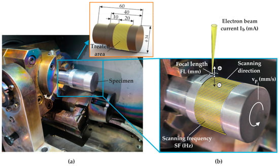
Figure 1.
EBH process: (a) general view of equipment used and specimen geometry; (b) EBH operating parameters.
2.3. EBH Implementation
The EBH process was performed using an Evobeam µEBW Cube 400 machine (Evobeam GmbH, Nieder-Olm, Germany) with a maximum irradiation power of . At constant voltage U = 60 kV, the irradiation power was controlled by regulating the electron beam current :
The electron beam diameter (focal spot) was . Thus, for a focal length () of zero, the area of the electron beam was approximately: . Based on the input energy density [48], the power density is defined as the ratio of the irradiation power to the electron beam area :
Figure 1a shows a general view of the equipment used. The operating parameters (governing factors) are visualized in Figure 1b. The treated area was symmetrically located on the specimen’s cylindrical surface to ensure uniform conductive heat transfer.
A one-factor-at-a-time technique was used to investigate the individual effects of the EBH operating parameters (governing factors). Table 1 shows the variation levels of the magnitudes of the governing factors. Within the investigated range of the electron beam current in the present study, the irradiation power varied in the range of .

Table 1.
Magnitudes of the governing factor used.
2.4. SI Characteristics Measurement
A Bruker D8 Advance X-ray diffractometer (Billerica, MA, USA) with a pinhole collimator with primary beam measurement was used to measure the RS. Table 2 shows the characteristics of the RS X-ray diffraction measurement. The object of X-ray diffraction analysis was the surface axial and hoop macro-RS, as well as their depth distributions after turning and after EBH. Electrolytic polishing was used to gradually removal the material surface layers to study the RS distribution in depth. A PROTO Electrolytic Polisher (Proto manufacturing Inc., Taylor, MI, USA) with electrolyte type E5 was used for the removal of these layers.
Table 2.
Characteristics of the X-ray measurement of RS in C45 steel.
The microstructures were observed by scanning electron microscopy (SEM) using a Zeiss Evo 10 microscope (Jena, Germany). The 2D roughness parameter was measured using a Mitutoyo Surftest SJ-210 surface roughness tester (Kawasaki, Japan). The average arithmetic values from the measurements on six equally spaced specimen generatrixes were obtained. A Bruker D8 Advance diffractometer with specialized software (DIFFRAC.EVA V5.2, Billerica, MA, USA) was used for phase analysis [48].
The procedure for preparing the samples for metallographic analysis includes the following steps: (1) embedding the sample in a resin containing a filler of copper particles; this filler provides the necessary electrical conductivity, which allows for subsequent examination by SEM; (2) grinding the sample using diamond discs with grits of 80, 220, 600, 1200 and 2400; (3) polishing the sample with suspensions containing abrasive particles with sizes of 3 μm and 1 μm; (4) etching the sample by treatment with a 5% nitric acid solution (Nital).
3. Results
3.1. Material Measurements
The main mechanical characteristics of the tensile-tested C45 steel in the as-received state were as follows: yield limit , tensile strength , and elongation %.
Figure 2 shows the phase analysis of the as-received steel. The diffractogram shows a distribution of α-Fe peaks characteristic of hypoeutectoid steels, which have a base structure comprising ferrite and pearlite.
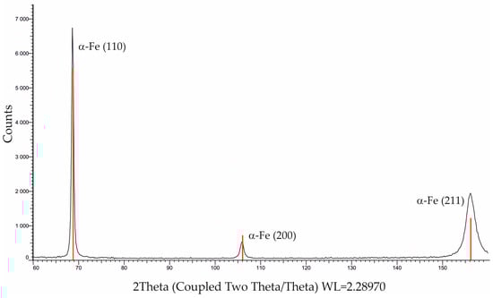
Figure 2.
Phase analysis of the as-received C45 steel.
Figure 3 shows a SEM image identifying the ferrite-pearlite structure of the as-received C45 steel.
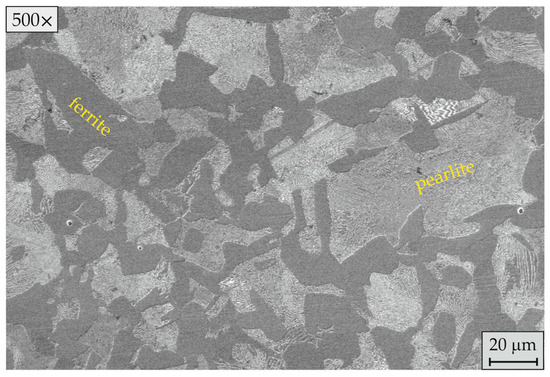
Figure 3.
Microstructure of the as-received C45 steel.
3.2. Roughness Parameter Evolution
The evolution of the roughness parameter after EBH is of interest for the following reasons: (1) is the most commonly used geometric characteristic of SI in engineering practice and has high functional importance for the operational behaviour of components; (2) in the absence of mechanical impact, the change in roughness after EBH indicates a surface remelting effect. Table 3 shows systematized information for the initial value of the roughness parameter (after turning) and the roughness parameter after EBH.
Table 3.
Evolution of the roughness parameter after EBH.
For all combinations of operating parameters, EBH caused a reduction in the initial roughness . Since the studied process is entirely thermal (there is no mechanical impact on the surface layer), the only reason for this phenomenon is the presence of a surface remelting effect. The only exception was observed for EBH with the lowest scanning frequency (SF) of 400 Hz ( and values are marked with “*” in Table 3). The SF parameter defines the number of linear scans of the electron beam in the axial direction in one second (Figure 1b). In fact, all processes using concentrated energy sources are characterized by a certain overlapping effect of the thermally affected zones generated by successive scans. Unlike the known methods of scanning rotational surfaces in a helical line (which exhibit an overlapping effect in the axial direction), the scanning mode in the novel EBH process results in the overlapping effect in a circumferential direction. Therefore, the reason for the deterioration of the roughness when the EBH was implemented with SF = 400 Hz was the uneven heating due to the large step between the scanning lines in the circumferential direction, which is reflected in a pronounced overlapping effect [47], resulting in a very rough topography (). The roughness evolution information in Table 3 shows a trend of a decreasing as the electron beam current and SF are increased. No clear trends were observed when changing the other two operating parameters.
3.3. Residual Stress
3.3.1. Effect of Electron Beam Current on RS
Figure 4 shows the effect of the electron beam current on the surface axial and hoop RS when the remaining three factors were fixed at constant intermediate values (see Table 1). The change in the magnitude of the electron beam current in the studied interval caused a change in both types of surface RS in a wide range: the axial RS varied from to , and the hoop RS varied from to .
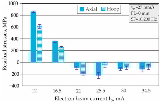
Figure 4.
Surface axial and hoop RSs depending on .
The smaller electron beam currents ( and ) led to large surface tensile axial and hoop RSs (Figure 4). These RSs were caused by the dominance of the high temperature gradient and very rapid solidification rates. The EBH implementation with the electron beam current in the interval increased the amount of heat introduced into the treated surface per unit time. The resulting thermal cycles favoured martensitic transformation, which has a larger volume than the parent structure [29,49]; consequently, compressive RSs were generated. The phase inhomogeneity near the surface was reflected in greater scattering of the measured RS.
Figure 5a,b shows the effect of the electron beam current on the distribution of axial and hoop RSs in depth. The profiles of the axial and hoop RSs after turning had a different character near the surface, and at a depth of 0.1 mm, they showed the presence of compressive RS, more pronounced for axial RS (the measured maximum compressive stress was ) (Figure 5a). The compressive RSs after turning were probably due to the rolling of the bars and plastic deformation introduced by the cutting insert. The implementation of EBH with caused significant tensile axial (Figure 5a) and hoop RS (Figure 5b). The use of larger electron beam currents ( and ) provided a zone with compressive axial and hoop RSs, and this effect was most pronounced at . The large PD created in this case intensified the structural and phase transformations, maximizing the compressive axial and hoop RSs, and the depth of the compressive zone reached 0.2 mm. Additionally, EBH implementation with led to the lowest roughness () as well as the largest roughness reduction after turning (Table 3). This result confirmed the significant surface remelting phenomenon due to the large .
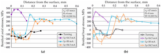
Figure 5.
Effect of on the RS distribution in depth: (a) axial; (b) hoop.
Structural and phase changes near the surface led to a greater scattering of the measured RS. This effect became more pronounced as the electron beam current increased.
3.3.2. Effect of Workpiece Peripheral Velocity on RS
Figure 6 shows the individual effect of the workpiece peripheral velocity on the surface axial and hoop RSs.
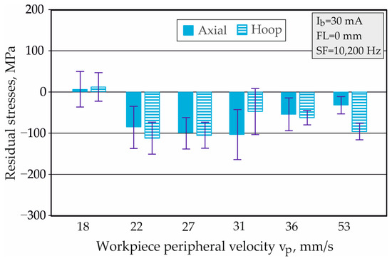
Figure 6.
Surface axial and hoop RSs depending on .
While other factors remained constant, the influence of the EBH process duration was estimated; for the studied interval of , this varied from 2.01–5.93 s. The implementation of the EBH process with the lowest velocity () led to the largest amount of heat input, reflected in insignificant tensile axial and hoop RSs. Increasing the workpiece peripheral velocity in the range of changed the RS to compressive. No clear trend was observed for the influence of on both types of RS. Considering the relatively large scattering of the measured RS, the variation in axial RS reached a maximum for resulting in a range of to . When the workpiece peripheral velocity changed in the range , the compressive hoop RSs exceeded the compressive axial ones, except for (Figure 6).
The workpiece peripheral velocity strongly influenced the distribution of axial and hoop RSs within the depth of the treated cylindrical surface (Figure 7a,b).
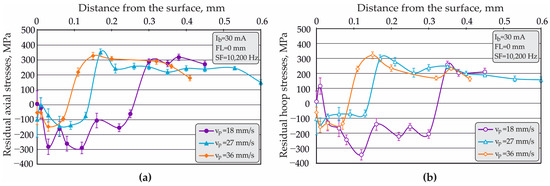
Figure 7.
Effect of on the RS distribution in depth: (a) axial; (b) hoop.
Increasing the and thus decreasing the duration of the EBH process significantly changed the RS profile and reduced the depth of the compressive zone for both types of RS. Regardless of the presence of small tensile surface stresses (Figure 6), the implementation of EBH with the smallest peripheral velocity ( = 18 mm/s) maximized the axial compressive RS (the maximum absolute value was ; Figure 7a), the hoop compressive RS (the maximum absolute value was ; Figure 7b), and the depth of the compressive zone for both types of RS to approximately 0.3 mm. Conversely, the workpiece peripheral velocities of and significantly reduced the maximum RS and the depth of the compressive zone to approximately 0.15 and 0.09 mm, respectively.
3.3.3. Effect of SF on RS
The variation in the SF in the studied interval significantly changed the surface axial and hoop RSs when the remaining three factors were maintained at constant values (Figure 8). The lowest value, caused uneven heating due to the large step between the scanning lines in the circumferential direction. As a result of the thermal interaction between successive scanning lines, significant surface axial and hoop tensile RSs with relatively large scattering and a very rough topography were generated (see Table 3). Conversely, the range of changed the trend towards compressive RS. This trend had a different character for axial and hoop RSs. Increasing the SF in the interval Hz led to greater surface hoop compressive RSs, which significantly exceeded the axial ones. Increasing the SF in the interval Hz led to greater surface axial compressive RSs (Figure 8).
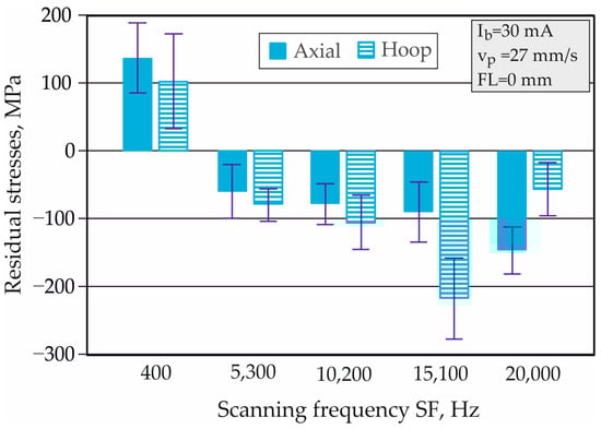
Figure 8.
Surface axial and hoop RSs depending on .
The influence of the SF on the distribution of axial and hoop RSs is shown in depth in Figure 9a,b, respectively. Similar trends were observed in the profiles of both types of RS: the increase in SF was reflected in a greater compression zone depth. At constant values of the other three operating parameters, the EBH implementation with the highest SF of led to maximum axial and hoop RSs and significantly increased the compressive zone depth to approximately 0.25 mm.
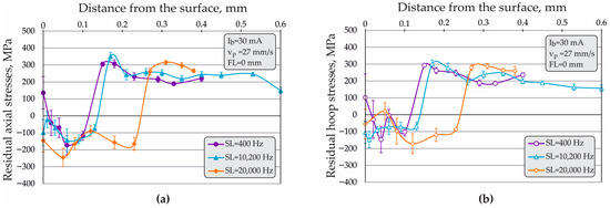
Figure 9.
Effect of on the RS distribution in depth: (a) axial; (b) hoop.
3.3.4. Effect of FL on RS
At fixed average values of the other EBH operating parameters, variation in the FL led to a significant change in the surface axial and hoop RSs due to the change in the area of the beam irradiating the surface (Figure 10). When the EBH was implemented with positive values of FL the focal spot was above the surface, and when the EBH was implemented with negative values of the FL the focal spot was below the surface (Figure 1b). Thus, the use of positive values of the FL leads to a lower surface temperature, limiting the martensitic transformation. In addition, the scattering of the measured surface RSs is the largest due to the surface remelting effect, causing deformation of the crystal lattices (texturing effect). Considering the inherent large scattering of the measured surface RS, the use of positive FLs in the interval showed a tendency towards tensile surface RS. Conversely, changing the FL from to stabilized the compressive RS, with this effect being more pronounced in the surface hoop RS.
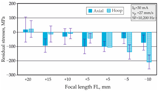
Figure 10.
Surface axial and hoop RSs depending on .
Figure 11a,b visualizes the influence of the FL on the distribution of axial and hoop RSs when the FL was varied in the symmetric interval from FL = to . Generally, a clustering of the obtained profiles of both types of RS was observed. Nevertheless, the implementation of EBH with and led to larger absolute values of the axial (Figure 11a) and hoop compressive RSs (Figure 11b). Additionally, the profiles of both types of RS formed smoother curves when the focal spot was below the surface (FL was negative), probably due to the less pronounced temperature gradient.
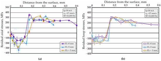
Figure 11.
Effect of on the RS distribution in depth: (a) axial; (b) hoop.
3.3.5. Experimental Study of the Repeatability of RS
A repeatability experiment was conducted to evaluate the ability of the studied EBH process to reproduce RSs. For this purpose, four specimens were subjected to EBH with the same operating parameters. The experimental results for the surface axial and hoop RSs were obtained as the arithmetic means of five equally spaced circumferential measurements in the centre of the treated cylindrical surface (Figure 12). The deviation between the obtained averaged surface axial RSs was , and the deviation between the hoop RSs was (Figure 12). The main factors determining the obtained deviations were the structural and phase inhomogeneity of the processed surface and uniform heating due to the overlapping effect in the circumferential direction [47].
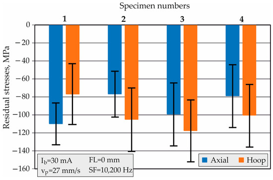
Figure 12.
The experimental results for the repeatability of the surface RS.
3.4. Microstructure
The individual effects of EBH operating parameters on SL microstructures were assessed by obtaining SEM images at different magnifications of two samples subjected to EBH with the same operating parameters except for the operating parameter under study.
3.4.1. Effect of Electron Beam Current on Microstructure
Figure 13a,b and Figure 14a,b show the microstructural modifications in the SLs of specimens subjected to EBH with the same operating parameters (, , ) but with different electron beam currents: and , respectively.
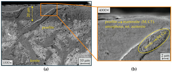
Figure 13.
Microstructure of the SLs after EBH with (a) magnification 1000×; (b) magnification 4000×.
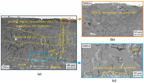
Figure 14.
Microstructure of the SLs after EBH with : (a) magnification 250×; (b) magnification 2000×; (c) magnification 1000×.
The EBH implementation with a smaller electron beam current () caused structural and phase changes at a depth of approximately 20 μm (Figure 13a). The short time and high temperature gradient prevented complete crystallization. Consequently, amorphous grains were formed in the liquid-solid regions at the liquid-solid transition, and the structure was inhomogeneous. The heating time and lower pearlite transformation temperature (727 °C) favoured the pearlite → austenite phase transformation in the pearlite colonies. As a result of the phase transformations ferrite → austenite → ferrite and the higher ferrite transformation temperature (911 °C), ferrite was preserved in the thermally affected SL, with low-carbon martensite (M; C↓) being registered (Figure 13b). Additionally, pearlite melted more easily than ferrite. Consequently, a mixture of liquid and solid phases was obtained in the SL, with the solid austenite phase undergoing a phase transformation to martensite. The high carbon content in the resulting martensite partially blocked the austenite → martensite (M; C↑) transformation and thus some retained austenite was obtained near the surface (Figure 13b).
The EBH implementation with the largest investigated electron beam current () increased the transition layer depth to approximately 225 μm, where three zones with characteristic phases and structural changes were formed (Figure 14a). In the upper SL, the significantly higher PD favoured the transformation of the two-phase structure into needle-like martensite, amorphous grains, and retained austenite (Figure 14b). In the intermediate zone, the thermal conditions led to a partial phase transformation of ferrite into low-carbon martensite. At the boundary with the bulk material, the pearlite colonies transformed into martensite, amorphous grains, and retained austenite (Figure 14c). The resulting modification of the microstructure led to an approximately threefold increase in the surface microhardness and hardened transition zone with a depth of approximately [47].
Figure 15 shows the phase analysis of the two specimens subjected to EBH with and . The diffractogram of the specimen subjected to EBH with shows the presence of retained austenite immediately below the surface due to the rapid solidification of the thin modified layer. Compared to the diffractogram in the as-received state (Figure 2), a broadening of the peaks in the diffractogram of the specimen subjected to EBH with was observed (Figure 15). This observation indicated the resulting pseudo-amorphous structure and microstrain in the upper SLs.
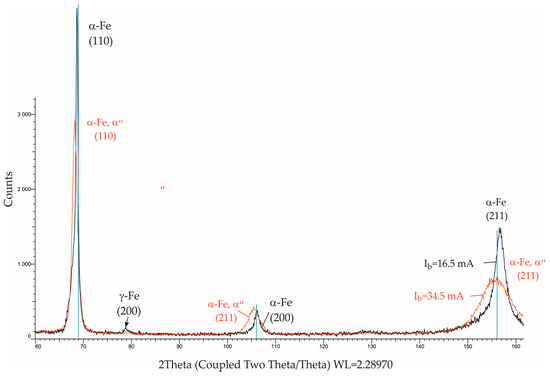
Figure 15.
Phase analysis of the specimens treated with different values.
3.4.2. Effect of Workpiece Peripheral Velocity on Microstructure
When the remaining operating parameters were fixed, the workpiece peripheral velocity determined the EBH process duration and the scanning velocity and hence the amount of heat introduced into the SL. The object of comparison was the SL microstructures in samples subjected to EBH with the same parameters ( 30 mA, and ), but with a different workpiece peripheral velocity: and .
Figure 16 shows the SL microstructure after EBH with a lower workpiece peripheral velocity (). This led to a longer heating time and a deeper phase transformation region (Figure 16a). Two zones were observed in the phase transformation region. At a depth of approximately 80 μm, the structural and phase changes resulted from the phase pretransformation ferrite + perlite → austenite → martensite + ferrite + retained austenite (Figure 16a). At higher magnifications, a very thin surface molten layer was observed (Figure 16b). The structural and phase inhomogeneity in the upper surface zone was due to the short time of hypereutectoid temperature ϕ and insufficient time for the diffusion processes to fully occur. The kinetic phase-building was associated with the diffusion process equalizing the carbon concentrations between the individual hereditary austenite grains formed from ferrite and pearlite (Figure 16b). After diffusion of the carbon from the hereditary pearlite colony (pearlite → austenite) and cooling after the termination of direct contact with the electron beam, a second phase transformation (recrystallization) occurred in the hereditary ferrite grains (ferrite → austenite). As a result of the additional dissolved carbon, the austenite formed from the ferrite grains transformed into martensite. The carbon was significantly reduced in the zones along the boundaries between the hereditary austenite grains (formed from ferrite and pearlite), which were produced as a ferrite phase after recrystallization.
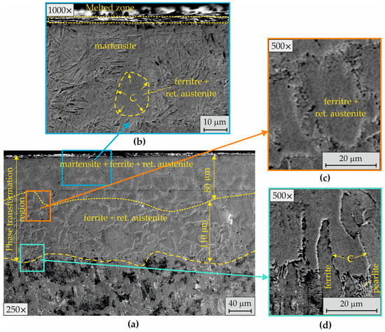
Figure 16.
Microstructure of the SLs after EBH with : (a) SL, magnification 250×; (b) SL, magnification 1000×; (c) heat-affected layer, magnification 500×; (d) transition between the heat-affected layer and base material, magnification 500×.
Due to the difficult diffusion, the increased amount of carbon, and the relatively high cooling rate, retained austenite was formed in the core of the pearlite colonies. The transfer of carbon between the two types of inherited austenite grains was difficult in the lower zone formed with a thickness of approximately 110 μm (Figure 16a) due to the lower temperature and insufficient time for the diffusion processes to occur. In this zone, no phase recrystallization of ferrite had occurred, and after cooling, the phase composition was ferrite and retained austenite (Figure 16c). Figure 16d visualizes the transition between the heat-affected SL and the base material.
Figure 17 shows the SL microstructure after EBH with twice the workpiece peripheral velocity (). The higher scanning velocity and half the irradiation time significantly reduced the thickness of the phase transformation zone to approximately 120 μm (Figure 17a). In the microstructure (Figure 17a), no additional zone with partial phase recrystallization was observed. At higher magnifications (Figure 17b,c), the microstructure confirmed the described mechanism of phase formation in the upper SL of the specimen treated with a lower workpiece peripheral velocity (Figure 16). Overall, the structure was more inhomogeneous due to the hindered diffusion of carbon during the gradient equalization of the concentrations of the hereditary austenite grains formed from ferrite and pearlite.
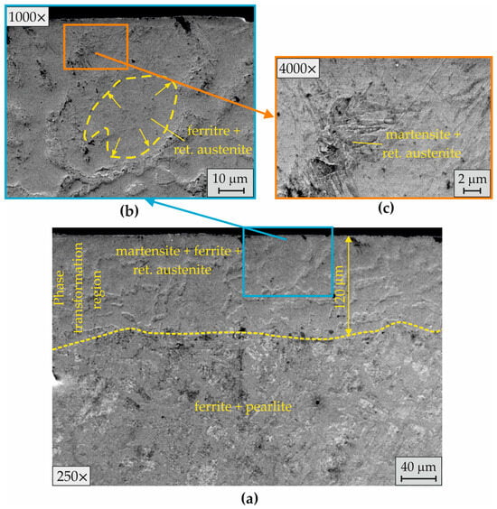
Figure 17.
Microstructure of the SLs after EBH with : (a) affected layer, magnification 250×; (b) SL, magnification 1000×; (c) SL, magnification 4000×.
The similar microstructures in the upper SL of the specimens treated with different peripheral workpiece velocities ( and ; Figure 16 and Figure 17) correlate with the phases recorded in the diffractograms of the two samples shown in Figure 18. The diffractogram of the specimen treated with twice the peripheral workpiece velocity shows a broadening of the line, indicating higher microstresses and greater dislocation densities due to the higher cooling rate. The indicated micro-effects in this case were reflected in the higher measured surface microhardness [47].
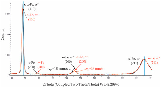
Figure 18.
Phase analysis of the specimens treated with different values.
3.4.3. Effect of SF on Microstructure
The variation in the defines the step between the scan lines in the circular direction and thus the overlapping effect in the same direction. The overlapping effect determines the processed surface homogeneity in terms of a temperature field, which correlates with the resulting surface topography [47]. In evaluating the effect of the SF, the objects of comparison were the surface morphology and the SL microstructures in specimens subjected to EBH with the same parameters ( 30 mA, and ), but with the largest difference in the SF: and .
Figure 19 shows the effect of the two SFs on surface morphology. The EBH implementation with caused a characteristic rough surface morphology due to the pronounced overlapping effect (Figure 19a). Conversely, the EBH implementation with provided a smoothing effect (Figure 19b; the roughness after EBH was ; Table 3).
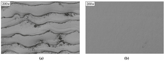
Figure 19.
Surface morphology depending on scanning frequency: (a) ; (b) .
Figure 20 shows the SL microstructure after EBH with the smallest investigated value of SF (). As shown in Figure 19a, this SF caused uneven heating and melting of the treated cylindrical surface. The phase transformation region (Figure 20a) included a surface zone with complete phase pretransformation and a thickness of approximately 59 μm and a thinner zone with partial phase pretransformation and a thickness of approximately 35 μm.
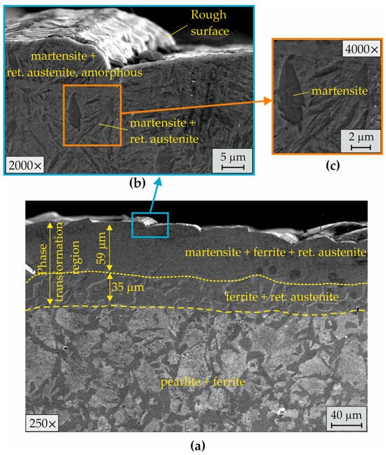
Figure 20.
Microstructure of the SLs after EBH with : (a) affected layer, magnification 250×; (b) SL, magnification 2000×; (c) SL, magnification 4000×.
Due to the non-uniform surface remelting effect, amorphous regions were formed between the grains in the upper SL (Figure 20b). Additionally, the resulting martensite was blocky and relatively coarse (Figure 20c).
Figure 21 shows the SL microstructure after EBH with the largest investigated . This scanning mode led to more heat generation in the SL for the same time and a significant reduction in the overlapping effect. Consequently, the thickness of the phase transformation region increased (Figure 21a) and the roughness was reduced (see Table 3) compared to the specimen treated with (Figure 20). Two characteristic zones with complete and partial pretransformation were observed in the modified SL. The created thermal conditions in this case favoured the formation of thicker zones, with thicknesses of 115 and 58 μm (Figure 21a). An additional advantage of this scanning mode was the formation of needle-block martensite in the surface zone of complete pretransformation (Figure 21b,c).
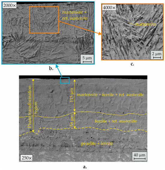
Figure 21.
Microstructure of the SLs after EBH with : (a) affected layer, magnification 250×; (b) SL, magnification 2000×; (c) SL, magnification 4000×.
The phases in the microstructures shown in Figure 20 and Figure 21 were confirmed by the phase analysis of the two specimens after EBH, but a difference in the registered peaks was observed (Figure 22). In the specimen treated with , more austenite was retained. Additionally, a broadening of the line was observed due to the more inhomogeneous surface structure containing amorphous regions.
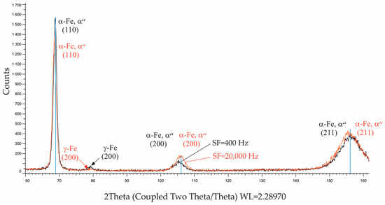
Figure 22.
Phase analysis of the specimens treated with different values.
3.4.4. Effect of FL on Microstructure
It is of practical and scientific interest to evaluate the influence of the FL on modifying the microstructure when it takes opposite values. Therefore, the object of comparison was the SL microstructures in specimens subjected to EBH with the same parameters ( 30 mA, and ), but with opposite FLs: and .
Figure 23 shows the microstructure in the SL after EBH with a positive . The phase transformation region in the SL included two zones: a surface zone with complete phase pretransformation at a depth of approximately and a second zone with partial pretransformation at a thickness of approximately (Figure 23a). The two zones are similar to the zones observed in the phase transformation region in Figure 16. Therefore, the phase transformation mechanism was similar to that described with respect to the microstructure shown in Figure 16. The thermal conditions due to the lower in this case favoured the formation of a more homogeneous surface structure containing low-carbon martensite. (Figure 23b,c).
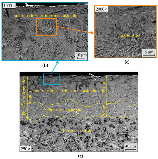
Figure 23.
Microstructure of the SLs after EBH with : (a) affected layer, magnification 250×; (b) SL, magnification 1000×; (c) SL, magnification 2000×.
Figure 24 shows the effect of the negative on the microstructure in the SL. Regarding the phase composition, the microstructure was similar to that obtained after EBH with . The focused heat below the surface in this mode resulted in a thicker surface zone with complete phase pretransformation (Figure 24a). As with the regime, low-carbon martensite was formed in the surface zone (Figure 24b,c).
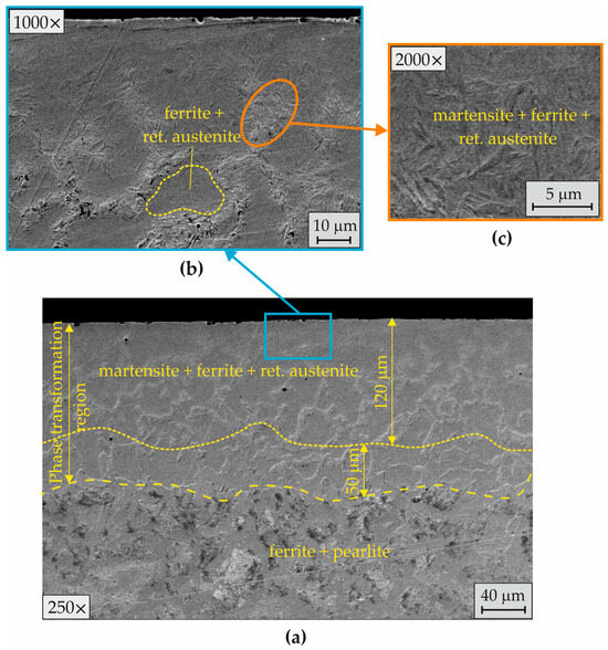
Figure 24.
Microstructure of the SLs after EBH with : (a) affected layer, magnification 250×; (b) SL, magnification 1000×; (c) SL, magnification 2000×.
Figure 25 shows the phase analysis of the two specimens treated with the indicated opposite FLs. The diffractograms are almost identical, and the retained austenite in the SL is relatively small. This confirms that EBH implementation with opposite FLs provided very close thermal conditions, resulting in similar microstructures containing low-carbon martensite and less retained austenite. This is evidenced by the measured identical maximum surface microhardnesses of the two specimens [47].
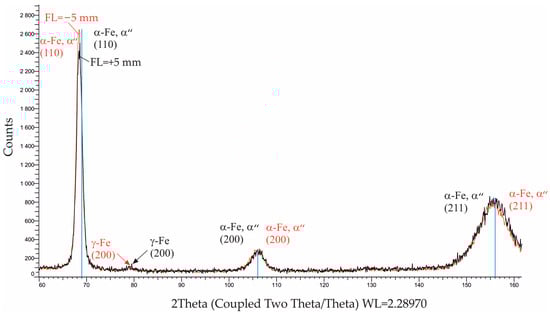
Figure 25.
Phase analysis of the specimens treated with different values.
4. Discussion
The studied EBH is a surface thermal process characterized by rapid heating of the SL followed by rapid cooling or self-quenching. The cooling rate is much faster than in traditional hardening methods [29,30]. Under these thermal conditions, the RSs arise from the following thermal effects in the SL: (1) thermoplastic deformations due to the temperature gradient and (2) phase transformations in the SL, typically forming martensite. Additionally, for a specific thermal cycle, the RS depends on two-phase material properties: thermal expansion/contraction coefficients and the yield strength. Since the RS corresponds to internal forces in the material after an applied external impact, noun arise as an elastic response to incompatible local deformations in the structural elements.
Depending on the ratio between the indicated thermal effects for a specific material, non-uniform thermal expansion and contraction, thermoplastic deformation, and phase inhomogeneity are created, which determine the qualitative and quantitative aspects of the RS distribution. The ratio between thermal effects (1) and (2) is determined by the thermal cycle, which depends on the specific combination of the EBH operating parameters. An appropriate selection of operating parameters in correlation with the thermal cycle is required to provide the desired hardening effect without compromising the material integrity. Diffusion processes and phase transformation depend on the temperature field in the SL and the heating and cooling time, which are largely determined by the electron beam current and workpiece peripheral velocity . The short-term temperature effect and large local temperature gradient are prerequisites for incomplete phase transformation and pronounced structural inhomogeneity in the SL.
The dominance of thermal effect (1) is manifested in strong heating and very rapid contraction/solidification of the surface. This process is opposed by slower cooling lower layers; thus, tensile RS are obtained in the SL. This formation mechanism of the tensile RS is typical for a heat affected zone in welded joints [49]. Based on 2D axisymmetric finite element modelling of rapid local heating and cooling of tempered martensite in medium carbon steel (with 90 vol% fine pearlite and 10 vol% proeutectoid ferrite), Cvetkovski et al. [32] found that RSs were generated by large thermal strain gradients to cause local plastic deformation. Consequently, the surface RSs are tensile, while the subsurface ones are compressive with a maximum value of approximately .
Effect (2) is manifested in the formation of a martensitic phase in the SL, which is harder and has a larger volume than the parent structure [29,49]. The increase in volume during the martensitic transformation causes a stress state in which the harder strengthened SL is confined by the underlying unstrengthened layers. Consequently, useful compressive RSs are generated in the SL.
As shown in Section 3.2, a surface remelting effect is present in the investigated range of the operating parameters of EBH. This effect causes a significant temperature gradient, thermoplastic deformation, and a smoothing effect on the surface. The reduction in the initial roughness is greater, as the electron beam current and SF (Table 3) are increased due to the larger and the weaker overlapping effect in the circumferential direction. Additionally, the resulting thermal cycles cause a rapid solidification microstructure containing amorphous grains (Figure 13, Figure 14, and Figure 20). Similarly, the surface remelting effect has been established for LBH of hot work tool steel AISI: H11 [35], low-carbon steel [37], and medium carbon steel [38], as well as for EBH of low-carbon steel [50].
The EBH implementation with small electron beam currents ( and ) favours the dominance of thermal effect (1) over thermal effect (2) due to the smaller heat input and the thinner modified layer (Figure 13a). Consequently, large tensile surface RSs are generated (for the axial and hoop stresses are 858.6 and 617.7 MPa, respectively; Figure 4). Conversely, the EBH implementation with the electron beam current in the range intensifies the martensitic transformation, which favours the formation of compressive surface axial and hoop RSs (Figure 4) and a compressive zone at a depth reaching 0.2 mm (Figure 5). The EBH implemented with the parameters , , , and favours the formation of needle-like martensite, amorphous grains, and retained austenite (Figure 14b). This microstructure provides maximum axial and hoop RSs of and , respectively.
When the remaining operating parameters are fixed, the decrease in the workpiece peripheral velocity is proportional to the irradiation time. Consequently, the martensitic transformation is intensified at greater depths, leading to a more intense and deeper zone with compressive RS. The EBH implementation with the lowest peripheral speed () provides maximum compressive axial and hoop RSs of (Figure 7a) and (Figure 7b), respectively, and a compressive zone at a depth of approximately 0.3 mm for both types of RS. The obtained RS profiles in this regime are correlated with the phase transformation region observed at a depth of approximately 0.2 mm (Figure 16). The EBH implementation with twice the peripheral velocity leads to a shallower phase transformation region (Figure 17), significantly reducing the maximum compressive axial and hoop RSs and tripling the depth of the compressive zone (Figure 7).
The EBH implementation with the smallest studied SF causes tensile axial and hoop surface RSs (Figure 8) due to the strongly pronounced overlapping effect in the circumferential direction, causing deterioration of the beam inhomogeneity [42], uneven heating, and solidification, and hence a characteristic markedly rough surface morphology (Figure 19a). Therefore, is inappropriate and should be excluded from the planned experiment on the EBH of C45 steel cylindrical specimens. Conversely, increasing the SF leads to the generation of more heat over a unit area for the same time and a reduction in the overlapping effect. Increasing the SF leads to the generation of more heat over a unit area for the same time, reduction in the overlapping effect, and, thus, improved homogeneity of the treated surface. When other factors remain constant, the highest maximizes axial and hoop RSs and significantly increases the compressive zone depth to approximately 0.25 mm (Figure 9a,b). These RS results correlate with the greater depth of the phase transformation region (Figure 21a) and the smooth surface morphology (Figure 19b).
According to the justification in [47], increasing the FL as an absolute value increases the electron beam area A interacting with the surface, reducing the PD. The clustering of the profiles of axial and hoop RSs when the EBH was implemented with opposite FLs ( and ; Figure 11a,b) largely confirms the justification in [47]. Notably, the profiles of both types of RS formed smoother curves when the FL was negative (). Additionally, when the focal spot was below the surface, a thicker surface zone with complete phase pretransformation was formed (Figure 24a). This regime probably leads to a less pronounced temperature gradient. Notably, both regimes provided modified surface zones containing low-carbon martensite and a smaller amount of retained austenite. Consequently, in these cases, a maximum median surface hardness of was measured [47]. The positive FLs in the interval caused tensile surface RSs (Figure 10); therefore, these are inappropriate for EBH of C45 steel.
It is of interest to compare the effect of the novel EBH process on the microstructure modification with that in rotational specimens made from low and medium-carbon steels obtained after LBH or EBH. For the studied combinations of EBH operating parameters, the microstructural analysis confirmed the transition from a hard surface zone with complete phase pretransformation, containing martensite, to a second zone with partial pretransformation to the ferrite and pearlite structure in the core. A similar modification of the microstructure was observed in C45 (SM45C) rod-shaped steel specimens after LBH with helical motion of the laser beam relative to the processed surface [36]. Near the surface, most of the matrix was transformed into martensite; with increasing depth, the retained austenite in the martensite phase increased; and at the boundary between the hardened zone and the matrix, a mixed structure containing austenite and ferrite was formed. It is important to emphasize that the scanning mode used causes a pronounced overlapping effect in the axial direction, reflected in a more complex structure in the periodic overlap interface. A transition from the martensitic structure to the ferrite and perlite structure was observed in a cross-section of AISI 1040 medium carbon steel fatigue specimens after LBH using a 1.5 kW high-power diode laser [37,38].
In contrast to microstructure studies, virtually no information exists on the RS introduced after EBH/LBH in rotational steel components. An exception is the study of the effect of LBH on RSs, microstructure, and fatigue behaviour of EA1N steel railway axles [39]. Using X-ray diffraction analysis, the authors reported a compressive RS exceeding −100 MPa after LBH. Within the laser-hardened track of the axle, a needle-shaped martensitic structure, interlaced with undissolved pearlite or Wiedmannscheite ferrite, prevailed. For comparison, it was found that the novel EBH process provided maximum compressive axial and hoop RSs of and , respectively, in C45 steel cylindrical specimens.
5. Conclusions
This study investigated the effectiveness of a novel EBH process for as-received C45 cylindrical specimens in terms of axial and hoop RSs and microstructure modification. A distinctive feature of the novel EBH process is the linear scanning mode in the axial direction, which eliminates the overlapping effect typically observed in the axial direction. Using a one-factor-at-a-time technique, the individual effects of the electron beam current , workpiece peripheral velocity , , and on the RS and microstructure in SL were evaluated. The major new findings of this study are as follows:
- The X-ray diffraction results for the surface axial and hoop RSs and the distribution of the two types of RS demonstrate the potential of the novel EBH for the formation of useful compressive RSs due to martensitic transformation in the SL.
- The SEM images of the surface microstructure confirmed the transition from a hard, surface zone with complete phase pretransformation, which contained martensite, a second zone with partial pretransformation, to the ferrite and pearlite structure in the core. The resulting gradient microstructure provided strengthened SLs and preserved bulk properties such as toughness and ductility; therefore, it is particularly suitable for rotating machine elements such as shafts and axles.
- The electron beam current in the range intensified the martensitic transformation, which favoured the formation of compressive surface axial and hoop RSs and a compressive zone at a depth reaching 0.2 mm. The EBH implemented with the parameters , , , and favoured the formation of needle-like martensite and amorphous grains in the SL; this microstructure provided the maximum axial and hoop RSs of and , respectively.
- The EBH implementation with the lowest peripheral speed of led to a deeper phase transformation region, which correlated with the measured maximum compressive axial and hoop RSs of and , respectively, and a compressive zone at a depth of approximately 0.3 mm for both types of RS.
- The highest maximized the generated heat over a unit area for the same time and minimized the overlapping effect in the circumferential direction, which provided the most homogeneous surface and smooth surface morphology. Consequently, the depth of the phase transformation region was significantly increased, the compressive axial and hoop RSs were maximized, and the compressive zone depth increased to approximately 0.25 mm.
- The EBH implementation with opposite FLs () provided similar thermal conditions, which caused similar modified surface zones containing low-carbon martensite and a smaller amount of retained austenite, practically identical phase analyses, and similar RS profiles with a pronounced compressive zone.
- The following limitations were established with respect to the suitable operating parameter ranges: (1) the electron beam current of was insufficient to enable martensitic transformation; (2) caused uneven heating and solidification, a characteristic markedly rough surface morphology, and tensile axial and hoop surface RS; (3) the positive FLs in the interval caused tensile surface axial and hoop RSs. After excluding these parameter values, the suitable ranges of the operating parameters were , and . The specified ranges are the basis for conducting a planned experiment on the novel EBH process, which will reflect the interactions between operating parameters.
Author Contributions
Conceptualization, G.D. and V.D.; methodology, G.D. and V.D.; software, V.D., M.A. and M.I.; validation, G.D., V.T. and Y.A.; formal analysis G.D. and V.D.; investigation, V.D., V.T., Y.A., M.A., M.I. and B.P.; resources, G.D., V.D. and V.T.; data curation, G.D. and V.D.; writing—original draft preparation, G.D. and V.D.; writing—review and editing, G.D. and. M.A.; visualization, G.D., Y.A. and B.P.; supervision, G.D.; project administration, G.D. and V.D.; funding acquisition, G.D. and V.D. All authors have read and agreed to the published version of the manuscript.
Funding
This research was funded by the European Regional Development Fund under the Operational Program “Scientific Research, Innovation and Digitization for Smart Transformation 2021–2027”, Project CoC “SmartMechatronics, Eco- and Energy Saving Systems and Technologies”, BG16RFPR002-1.014-0005.
Data Availability Statement
The original contributions presented in the study are included in the article; further inquiries can be directed to the corresponding author.
Conflicts of Interest
The authors declare no conflicts of interest.
Abbreviations
| Abbreviations | |
| EBH | Electron beam hardening |
| Focal length | |
| LBH | Laser beam hardening |
| Power density | |
| RSs | Residual Stresses |
| Scanning frequency | |
| SI | Surface integrity |
| SL | Surface layer |
| List of Symbols | |
| Electron beam area | |
| Electron beam diameter | |
| Electron beam current | |
| Irradiation power | |
| Arithmetic average of roughness profile after EBH | |
| Arithmetic average of roughness profile after turning | |
| Workpiece peripheral velocity | |
References
- Astakhov, V. Surface integrity–definition and importance in functional performance. In Surface Integrity in Machining; Springer: London, UK, 2010; pp. 1–35. [Google Scholar]
- Dwivedi, D. Characterization of Engineered Surfaces. In Surface Engineering: Enhancing Life of Tribological Components; Springer: New Delhi, India, 2018; pp. 171–215. [Google Scholar]
- Maximov, J.; Duncheva, G. The correlation between surface integrity and operating behaviour of slide burnished components—A review and prospects. Appl. Sci. 2023, 13, 3313. [Google Scholar] [CrossRef]
- Fischer, A.; Berthold, S.; Niendorf, T. On the Influence of Surface Hardening Treatments on Microstructure Evolution and Residual Stress in Microalloyed Medium Carbon Steel. J. Mater. Eng. Perform. 2020, 29, 3040–3054. [Google Scholar] [CrossRef]
- Lesyk, D.; Mordyuk, B.; Alnusirat, W.; Martinez, S.; Dzhemelinskyi, V.; Goncharuk, O.; Kondrashev, P.; Klyuchnikov, Y.; Lamikiz, A. Ultrasonic surface finishing of AISI 1045 steel hardened by laser heat treatment with fibre laser and scanning optics: Layered-structure-induced hardening and enhanced surface morphology. Prog. Phys. Met./Usp. Fiz. Met. 2024, 25, 822–867. [Google Scholar]
- Kikuchi, S.; Minamizawa, K.; Arakawa, J.; Akebono, H.; Takesue, S.; Hayakawa, M. Combined effect of surface morphology and residual stress induced by fine particle and shot peening on the fatigue limit for carburized steels. Int. J. Fatigue 2023, 168, 107441. [Google Scholar] [CrossRef]
- Duncheva, G.; Maximov, J. Cold working technologies for increasing the fatigue life of metal structural components with fastener holes—Review and perspectives. Int. J. Adv. Manuf. Technol. 2025, 136, 2909–2943. [Google Scholar] [CrossRef]
- Han, X.; Zhang, Z.; Wang, B.; Thrush, S.; Barber, G.; Qiu, F. Microstructures, compressive residual stress, friction behavior, and wear mechanism of quenched and tempered shot peened medium carbon steel. Wear 2022, 488, 204131. [Google Scholar] [CrossRef]
- Dwivedi, P.; Rai, A.; Ganesh, P.; Ranganathan, K.; Bindra, S.; Dutta, K. Effect of laser shock peening on microstructure and micro-texture evolution in high-strength low-alloy steel upon electrochemical interaction. J. Mater. Eng. Perform. 2024, 33, 5206–5222. [Google Scholar] [CrossRef]
- Velázquez-Corral, E.; Llumà, J.; Jerez-Mesa, R.; Wagner, V.; Dessein, G.; Travieso-Rodriguez, J. Fatigue enhancement and hardening effect through ultrasonic vibration-assisted ball-burnishing process on AISI 1045 steel. Fatigue Fract. Eng. Mater. Struct. 2024, 47, 203–219. [Google Scholar] [CrossRef]
- Zhao, Y.; Gong, B.; Liu, Y.; Zhang, W.; Deng, C. Fatigue behaviors of ultrasonic surface rolling processed AISI 1045: The role of residual stress and gradient microstructure. Int. J. Fatigue 2024, 178, 107993. [Google Scholar] [CrossRef]
- Qin, T.; Ao, N.; Ren, X.; Zhao, X.; Wu, S. Determination of optimal ultrasonic surface rolling parameters to enhance the fatigue strength of railway axle EA4T steel. Eng. Fract. Mech. 2022, 275, 108831. [Google Scholar] [CrossRef]
- Balusamy, T.; Sathyaraj, P.; Ravichandran, K.; Narayanan, T. Influence of surface mechanical attrition treatment parameters on the residual stress of EN8 steel. J. Mater. Eng. Perform. 2024, 33, 7679–7688. [Google Scholar] [CrossRef]
- Noronha, D.; Sharma, S.; Parkala, R.; Shankar, G.; Kumar, N.; Doddapaneni, S. Deep rolling techniques: A comprehensive review of process parameters and impacts on the material properties of commercial steels. Metals 2024, 14, 667. [Google Scholar] [CrossRef]
- de Oliveira, D.; Martins, A.; dos Santos, A.; de Castro MagalhŃes, F.; AbrŃo, A. Influence of the hydrostatic ball burnishing on surface quality and ultra-microhardness. J. Braz. Soc. Mech. Sci. Eng. 2024, 46, 74. [Google Scholar] [CrossRef]
- Maximov, J.; Duncheva, G. Effects of diamond burnishing on surface integrity, fatigue, wear, and corrosion of metal components—Review and perspectives. Int. J. Adv. Manuf. Technol. 2025, 139, 4233–4267. [Google Scholar] [CrossRef]
- Maximov, J.; Duncheva, G.; Ichkova, M.; Anastasov, K. Optimal Diamond Burnishing of Chromium–Nickel Austenitic Stainless Steels Based on the Finishing Process–Surface Integrity–Operating Behavior Correlations. Metals 2025, 15, 574. [Google Scholar] [CrossRef]
- Hurey, I.; Gurey, V.; Bartoszuk, M.; Hurey, T. Formation of residual stresses during discontinuous friction treatment. J. Eng. Sci. 2021, 8, C38–C44. [Google Scholar] [CrossRef]
- Minamizawa, K.; Arakawa, J.; Akebono, H.; Nambu, K.; Nakamura, Y.; Hayakawa, M.; Kikuchi, S. Fatigue limit estimation for carburized steels with surface compressive residual stress considering residual stress relaxation. Int. J. Fatigue 2022, 160, 106846. [Google Scholar] [CrossRef]
- Taweejun, N.; Praditja, T.; Bootchai, S.; Kanchanomai, C. Effect of multi-cycle nitrocarburizing on the microstructure and surface hardness of low-carbon steel. Met. Sci. Heat Treat. 2021, 63, 380–387. [Google Scholar] [CrossRef]
- Hoja, S.; Baustert, R.; Hasselbruch, H.; Steinbacher, M.; Fechte-Heinen, R. Investigation of combined surface treatments and coatings to increase the wear behavior of heat treatable steels. Surf. Coat. Technol. 2023, 472, 129929. [Google Scholar] [CrossRef]
- Marichamy, S.; Dhinakaran, V.; Stalin, B.; Ravichandran, M.; Balasubramanian, M.; Chairman, C. Taguchi optimization and flame hardening experimental investigation on eglin steel. IOP Conf. Ser. Mater. Sci. Eng. 2020, 988, 012099. [Google Scholar] [CrossRef]
- Thamilarasan, J.; Karunagaran, N.; Nanthakumar, P. Optimization of oxy-acetylene flame hardening parameters to analysis the surface structure of low carbon steel. Mater. Today Proc. 2021, 46, 4169–4173. [Google Scholar] [CrossRef]
- Stević, Z.; Dimitrijević, S.; Stević, M.; Stolić, P.; Petrović, S.; Radivojević, M.; Radovanović, I. The design of a system for the induction hardening of steels using simulation parameters. Appl. Sci. 2023, 13, 11432. [Google Scholar] [CrossRef]
- Holmberg, J.; Steuwer, A.; Stormvinter, A.; Kristoffersen, H.; Haakanen, M.; Berglund, J. Residual stress state in an induction hardened steel bar determined by synchrotron-and neutron diffraction compared to results from lab-XRD. Mater. Sci. Eng. 2016, 667, 199–207. [Google Scholar] [CrossRef]
- Qin, T.; Hu, F.; Xu, P.; Zhang, H.; Zhou, L.; Ao, N.; Su, Y.; Shobu, T.; Wu, S. Gradient residual stress and fatigue life prediction of induction hardened carbon steel S38C axles: Experiment and simulation. Int. J. Fatigue 2024, 185, 108336. [Google Scholar] [CrossRef]
- Muthukumaran, G.; Babu, P. Laser transformation hardening of various steel grades using different laser types. J. Braz. Soc. Mech. Sci. Eng. 2021, 43, 103. [Google Scholar] [CrossRef]
- Wang, J.; Xia, J.; Liu, Z.; Xu, L.; Liu, J.; Xiao, Y.; Gao, J.; Ru, H.; Jiao, J. A comprehensive review of metal laser hardening: Mechanism, process, and applications. Int. J. Adv. Manuf. Technol. 2024, 134, 5087–5115. [Google Scholar] [CrossRef]
- Łach, Ł. Recent advances in laser surface hardening: Techniques, modeling approaches, and industrial applications. Crystals 2024, 14, 726. [Google Scholar] [CrossRef]
- Valkov, S.; Ormanova, M.; Petrov, P. Electron-beam surface treatment of metals and alloys: Techniques and trends. Metals 2020, 10, 1219. [Google Scholar] [CrossRef]
- Kiefer, D.; Schüssler, P.; Mühl, F.; Gibmeier, J. Experimental and simulative studies on residual stress formation for laser-beam surface hardening. HTM J. Heat Treat. Mater. 2019, 74, 23–35. [Google Scholar] [CrossRef]
- Cvetkovski, K.; Ahlström, J.; Karlsson, B. Influence of short heat pulses on properties of martensite in medium carbon steels. Mater. Sci. Eng. 2013, 561, 321–328. [Google Scholar] [CrossRef]
- Muthukumaran, G.; Babu, P. Analysis of residual stress distribution and corrosion in laser surface hardened low alloy steel with a flat top-hat laser beam, using a high-power diode laser. Arab. J. Sci. Eng. 2022, 47, 8785–8803. [Google Scholar] [CrossRef]
- Lu, Y.; Ehle, L.; Richter, S.; Radel, T. Influence of multi-pass laser hardening of normalized AISI 4140 on the grain size. Surf. Coat. Technol. 2021, 421, 127434. [Google Scholar] [CrossRef]
- Preußner, J.; Oeser, S.; Pfeiffer, W.; Temmler, A.; Willenborg, E. Microstructure and residual stresses of laser remelted surfaces of a hot work tool steel. Int. J. Mater. Res. 2014, 105, 328–336. [Google Scholar] [CrossRef]
- Jong-Do, K.I.M.; Myeong-Hoon, L.E.E.; Su-Jin, L.E.E.; Woon-Ju, K.A.N.G. Laser transformation hardening on rod-shaped carbon steel by Gaussian beam. Trans. Nonferrous Met. Soc. China 2009, 19, 941–945. [Google Scholar] [CrossRef]
- Guarino, S.; Barletta, M.; Afilal, A. High Power Diode Laser (HPDL) surface hardening of low carbon steel: Fatigue life improvement analysis. J. Manuf. Process. 2017, 28, 266–271. [Google Scholar] [CrossRef]
- Ponticelli, G.; Guarino, S.; Giannini, O. An optimal genetic algorithm for fatigue life control of medium carbon steel in laser hardening process. Appl. Sci. 2020, 10, 1401. [Google Scholar] [CrossRef]
- Čapek, J.; Trojan, K.; Kec, J.; Ganev, N.; Černý, I.; Mužík, T. Residual Stresses and the Microstructure of Modeled Laser-Hardened Railway Axle Seats under Fatigue. Metals 2024, 14, 290. [Google Scholar] [CrossRef]
- Śliwiński, P.; Węglowski, M.; Kwieciński, K.; Wieczorek, A. Electron beam surface hardening. Biul. Inst. Spaw. 2022, 66, 7–20. [Google Scholar] [CrossRef]
- Matlák, J.; Dlouhý, I. Properties of electron beam hardened layers made by different beam deflection. Manuf. Technol. 2018, 18, 279–284. [Google Scholar] [CrossRef]
- Fu, Y.; Hu, J.; Shen, X.; Wang, Y.; Zhao, W. Surface hardening of 30CrMnSiA steel using continuous electron beam. Nucl. Instrum. Methods Phys. Res. Sect. B Beam Interact. Mater. At. 2017, 410, 207–214. [Google Scholar] [CrossRef]
- Choo, S.; Lee, S.; Golkovski, M. Effects of accelerated electron beam irradiation on surface hardening and fatigue properties in an AISI 4140 steel used for automotive crankshaft. Mater. Sci. Eng. 2000, 293, 56–70. [Google Scholar] [CrossRef]
- Śliwiński, P.; Węglowski, M.; Wieczorek, A.; Skołek, E. Electron beam hardening of nanobainitic steel. Surf. Eng. 2024, 40, 276–283. [Google Scholar] [CrossRef]
- Petrov, P. Optimization of carbon steel electron-beam hardening. J. Phys. Conf. Ser. 2010, 223, 12–29. [Google Scholar] [CrossRef]
- Fu, Y.; Hu, J.; Zhang, X.; Huo, W.; Cao, X.; Zhao, W. Surface modification of AISI 1045 steel by pseudospark based pulsed electron beam. Nucl. Instrum. Methods Phys. Res. Sect. B Beam Interact. Mater. At. 2018, 434, 88–92. [Google Scholar] [CrossRef]
- Anchev, A.; Stoyanov, B.; Atanasova, M.; Argirov, Y.; Petkov, B. Improving in microhardness of C45 steel obtained via electron beam hardening using a one factor-at-a-time technique. Int. J. Innov. Res. Sci. Stud. 2025, 8, 1255–1270. [Google Scholar] [CrossRef]
- DIFFRAC.DQUANT V1.5; Quantitative Analysis from Calibration to Reporting. Bruker AXS GmbH: Karlsrue, Germany, 2018.
- Falodun, O.; Oke, S.; Bodunrin, M. A comprehensive review of residual stresses in carbon steel welding: Formation mechanisms, mitigation strategies, and advanced post-weld heat treatment techniques. Int. J. Adv. Manuf. Technol. 2025, 136, 4107–4140. [Google Scholar] [CrossRef]
- Guan, Q.F.; Zou, H.; Zou, G.; Wu, A.M.; Hao, S.Z.; Zou, J.X.; Qin, Y.; Dong, C.; Zhang, Q.Y. Surface nanostructure and amorphous state of a low carbon steel induced by high-current pulsed electron beam. Surf. Coat. Technol. 2005, 196, 145–149. [Google Scholar] [CrossRef]
Disclaimer/Publisher’s Note: The statements, opinions and data contained in all publications are solely those of the individual author(s) and contributor(s) and not of MDPI and/or the editor(s). MDPI and/or the editor(s) disclaim responsibility for any injury to people or property resulting from any ideas, methods, instructions or products referred to in the content. |
© 2025 by the authors. Licensee MDPI, Basel, Switzerland. This article is an open access article distributed under the terms and conditions of the Creative Commons Attribution (CC BY) license (https://creativecommons.org/licenses/by/4.0/).