Article

Tailoring the Functional Properties of NiTi Shape Memory Alloy by Laser Powder Bed Fusion Process Conditions for 4D Printing

by
Stanislav V. Chernyshikhin
1,*,
Dmitry D. Zherebtsov
1,
Leonid V. Fedorenko
1,
Vladimir Yu. Egorov
1,
Viktor O. Filinov
1,
Stanislav O. Rogachev
1,*,
Andrey N. Urzhumtsev
1,
Ella L. Dzidziguri
1,
Maria V. Lyange
1 and
Igor V. Shishkovsky
2
1
National University of Science and Technology MISIS, 119049 Moscow, Russia
2
Laboratory of Laser Applications, Lebedev Physical Institute, 443011 Samara, Russia
*
Authors to whom correspondence should be addressed.
J. Manuf. Mater. Process. 2025, 9(12), 385; https://doi.org/10.3390/jmmp9120385 (registering DOI)
Submission received: 23 October 2025 / Revised: 8 November 2025 / Accepted: 20 November 2025 / Published: 23 November 2025

Abstract

Over the last decade, laser powder bed fusion (LPBF) received increased attention as a method of producing complex-shaped products from various materials. Recent results indicate the potential of this technology for the production of intermetallic NiTi alloys with shape memory. Several studies have demonstrated a strong influence of the LPBF process conditions on the resulting material properties, i.e., the martensitic phase transformation temperatures, reversible/irreversible strain after cyclic loading, phase composition, chemical composition, etc. However, the mechanisms of functional properties altering during LPBF consolidation remain unexplored in the present state-of-the-art. This study aims to advance the knowledge about tailoring material properties of NiTi under laser influence. In this work, thin-walled samples were manufactured from pre-alloyed NiTi powder via LPBF in a wide window of laser power and scanning speed, excluding hatch spacing by employing a single track-based scanning strategy to reveal the pure effect of the laser’s influence. NiTi samples were characterized by various methods such as differential scanning calorimetry, X-ray diffraction, and mechanical tests. Established relationships between NiTi properties and the LPBF process conditions provide the basis for the development of NiTi production protocols with controlled functional properties.

1. Introduction

Nitinol is a shape memory alloy (SMA) with an equiatomic composition in a nickel—titanium system. The recoverable strain for nitinol reaches 8% [1], which is higher than other SMAs (5% for Cu-based and less than 5% for Fe-based [2]). The purely elastic strain value for conventional structural steels is an order of magnitude lower than the recoverable strain of NiTi. Obtaining such non-trivial properties in SMAs allows for solving engineering problems in several areas at a new technological level.
High mechanical strength and relatively low modulus of elasticity are essential characteristics of the NiTi alloy as a biomedical material [3]. These properties make this SMA an excellent material for various implants, such as dental implants, joints, and spine fixators [4]. Other distinctive applications of Nitinol include actuators, fittings, and valves [5]. For some medical devices like coronary stents, dental files, and braces, such material is indispensable [6].
The machining of nitinol is known to be a tedious process due to the strongly pronounced strain-hardening effect, unconventional stress–strain characteristics, and high ductility of the material [7]. Those peculiarities lead to unsuitable cheap formation, poor surface finish, and increased wear of cutting tools during the milling of NiTi [8]. These limitations restrict the manufacturing of nitinol in the form of rods and plates [9], which require additional manufacturing steps, such as cutting [1], welding [10], or drilling [11]. Conventional powder metallurgy and casting are also complicated, due to the absorption of impurities [12], the formation of metastable intermetallic phases [9], and the inhomogeneous mixing of the liquid phase [13]. As a result, attempts have been made to manufacture this material, using different approaches such as additive manufacturing (AM).
Laser powder bed fusion (also known as selective laser melting (SLM)) is an AM technology that is suitable for manufacturing metal parts with great dimensional accuracy—deviation from the nominal dimensions is less than 100 µm [14]. Another important aspect of technology is resolution, or the smallest feature that can be manufactured. In our previous paper [15], a minimum wall thickness of 54 ± 10 μm was achieved for NiTi thin-walled samples. The ability to manufacture complex geometric shapes with thin walls allows for the production of lightweight constructions, topologically optimized parts, structural objects, patient-specific implants, etc. At the same time, a wide area of required research is in demand, since factors such as laser irradiation impact, the effect of feedstock material, and the melting mode should be taken into account and carefully considered.
LPBF has opened up new opportunities in the manufacturing of NiTi and has overcome the challenges associated with conventional approaches [16]. Nevertheless, it should be noted that intermetallic materials, such as TiAl, NiAl, NiTi, etc. [17,18,19], are known to have a narrow window of optimal process parameters; therefore, optimization and fine-tuning are required for successful consolidation. Many studies have shown that various macro and micro defects can be observed in the printed material [20,21,22,23,24]. Macro defects, primarily caused by large residual thermal stresses induced by laser processing with high-temperature gradients, include cracking and delamination from commercially available base plates. Micro defects can be subdivided into metallurgical pores, microcracks, and pores caused by the lack of fusion defects [23,24,25,26].
The combination of AM and SMA gives rise to 4D printing, involving the consideration of altering the shape and properties over time, which gives new applications of nitinol [27,28]. This field of research will be discussed further. One of the most important issues in the adaptation of AM to industrial applications is understanding the process conditions and properties relationship. Most of the works are dedicated to studying the effect of process parameters on basic mechanical properties such as tensile strength, elongation to fracture, hardness, etc. However, in the case of smart materials, 3D printing and additional properties should be investigated. A NiTi alloy may exhibit completely different responses to external stimuli (load, heating), depending on the transformation temperatures (TTs). Thus, the relationship of the process condition and NiTi functional properties has created a new field for research.
Any domain of material experiences remelting more than once to provide decent metallurgical contact between the adjacent layers. Such a condition causes the appearance of complex thermal history with multiple cycles of heating/remelting [29]. As far as that influence leads to structural changes, it can be considered as the in situ heat treatment during the LPBF process. In terms of Ni-rich nitinol, excessive Nickel may form precipitation particles—particularly Ni4Ti3—once thermodynamically favorable conditions are reached [30]. It is known from pioneer works on the heat treatment and metallurgy of NiTi that the precipitation temperature range can be considered to be 400–800 °C [31]. The complexity of in situ heat treatment recognition is associated not only with precipitation formation during heating but also with possible evaporation during remelting of the domain.
It is known that the LPBF process for NiTi is accompanied by a change in the TTs of the final product, depending on the technological parameters. Nevertheless, there is a limited number of studies on TTs dependencies [15,32,33,34,35]. It was shown by Ma et al. [32] that by changing of hatch distance from 35 µm to 120 µm for different arms of a 3D-printed clamp’s different stimulus-response characteristics were achieved in an as-built state. It was demonstrated that the strain recovery of an arm manufactured with 120 µm occurs at 60 °C, when for an arm obtained with a hatch distance of 35 µm, the shape memory appeared at a temperature of 0 °C. Moreover, it was demonstrated by Moghaddam et al. [33] that the hatch distance among other LPBF process parameters has the highest influence on the TTs of the consolidated part. To achieve the superelastic behavior in the as-built state, the hatch distance was varied from 80 to 180 um. The sample produced with an 80 µm hatch distance resulted in 5.62% strain recovery and a 98% recovery ratio, with a stabilized strain recovery of 5.2% after 10 loading/unloading cycles. In our previous work [34], a shift in the martensite phase transformation was observed after laser polishing of NiTi samples produced by LPBF. The martensite phase transformation of the high liner energy density sample was shifted to a lower temperature, while the hysteresis of the transformation was not affected. In another work [15], we demonstrated a change in characteristic transformation temperatures in comparison with raw powder for high resolution LPBF.
Apart from the reviewed facts, the dependence of functional properties altering during the laser influence has been insufficiently studied. Furthermore, reported findings emphasize the effect of the hatch spacing on the resulting TTs [15,32,33,34,35], while there have been no studies on thin-walled samples when this parameter is excluded. Thus, this research aims to study the altering of NiTi’s functional properties after the LPBF consolidation of thin-walled objects was obtained via single-track-based scanning strategy. Excluding the hatch spacing will shed light on the pure effect from the laser power and scanning speed.

2. Materials and Methods

NiTi powder produced by NiTiMet Co., Ltd. (Moscow, Russia) was used in this work as a raw material. The powder was obtained by the electrode induction-melting gas atomization technique. Oxygen content was measured by the inert gas fusion method, using ONH-3500 (NCS Testing Technology Co., Ltd., Beijing, China). The flowability of powder was characterized by the Hall flowmeter as the time required to flow 50 g of powder through the Hall funnel. The measurements of the tap density were conducted according to the ASTM B527 standard [36]. The particle size distribution (PSD) was obtained by a laser diffraction method using Analysette 22 (Fritsch, Idar-Oberstein, Germany). The differential and integral distributions are shown in Figure 1. PSD has unimodal, Gaussian, and continuous distribution. The powder’s physical properties are given in Table 1.
The experiments were performed on a TruPrint 1000 (Trumpf, Ditzingen, Germany) LPBF machine, equipped with a CW ytterbium fiber laser (wavelength of 1070 nm). The laser beam profile yielded the Gaussian power density distribution (TEM00), with a spot size diameter of 55 μm and a maximum laser power of 200 W. The chamber was filled with argon to prevent the nitinol samples from assimilating hydrogen, nitrogen, and oxygen; the oxygen content in the chamber was less than 0.01%. A NiTi sheet with a thickness of 4 mm was used for an in-house built base plate. Chamfered holes were made in the sheet for fastening with countersunk head screws (Figure 2), using a CNC milling machine Mikron HPM 800 (GF Machining Solutions, Biel/Bienne, Switzerland).
The data files for the Trumpf 1000 installation were prepared with Materialise Magic’s slicing software v. 25.02 (Materialise, Leuven, Belgium). All thin-walled objects were sliced as support, to implement a single track-based strategy without a contour scan. Process parameters (laser power and scanning speed) are presented in Table 2. The window of process parameters was selected based on our previous works [15,25]. The linear energy density (El) was calculated according to Equation (1):
E l = P V
Further, the samples are designated by their main parameters: for example, P100V200 is a specimen consolidated by a laser power of 100 W and a scanning speed of 200 mm/s. The layer thickness of 20 µm was kept constant for all thin-walled samples.
Differential scanning calorimetry (DSC) measurements were carried out on the 823E Module (Mettler Toledo, Greifensee, Switzerland) with a liquid nitrogen cooling system. The melting points and enthalpies of indium and zinc were used for the temperature and heat capacity calibration. Samples weighing 8–10 mg were cut from the central part of the plate and placed in 40 μL aluminum pans. Before the analysis, the plates were ground with 2500 grit SiC sandpaper to remove the thermal response of residual powder. Calorimetry was performed in the range from −100°C to 100°C, with a rate of 10°/min under an argon atmosphere. Before the actual cycle, the samples were heated up to 100 °C to ensure a fully austenitic phase at the start of measurements.
The phase composition was investigated via X-ray diffraction (XRD) analysis using the Difrey 401 diffractometer (Scientific Instruments, Saint Petersburg, Russia). The measurements were carried out at room temperature using an X-ray tube with Cu-Kα radiation (wavelength 0.1504 nm), and Bragg–Brentano focusing. The phase composition of the samples was identified using the 1999 PDF2 X-ray database and BaseDifract (ver. 2.01). The samples were prepared from plates that were ground in a similar manner to the DSC measurements. The minimum grain size of abrasive particles helps to decrease stresses in the near-surface region, which affects the results of the XRD analysis [37]. In general, sample preparation is required to prevent the appearance of X-ray diffraction peaks in the residual powder adhered to the surface.
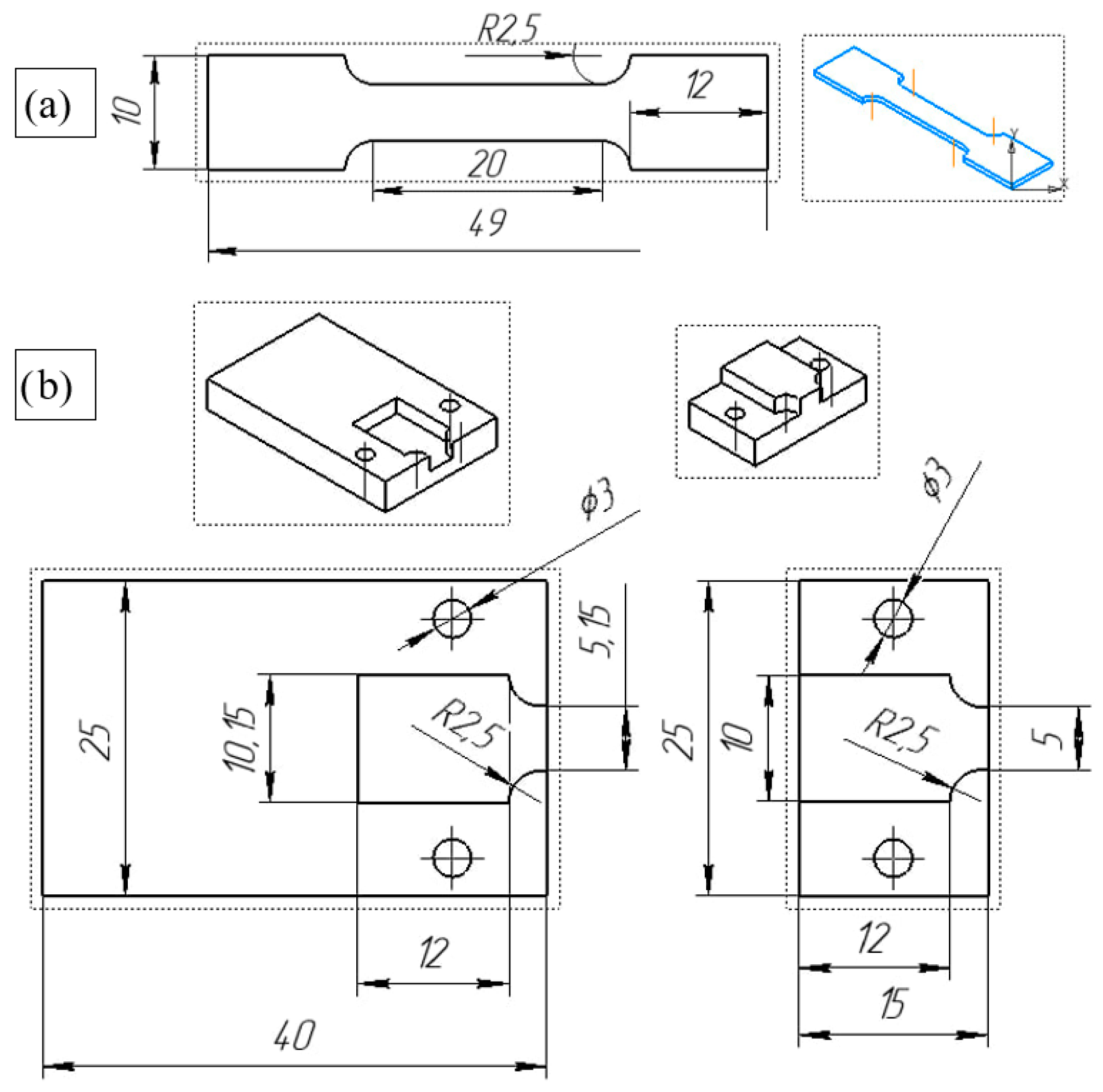
The mechanical test samples were cut in a flat dog-bone form, according to drawings in Figure 3a. Cutting was carried out using electrical discharge machining (EDM) on a GX-320L (CHMER EDM, Hangzhou, China). The distance between the shoulders could be reduced, due to the utilization of a non-contact deformation measurement system that does not require additional gauge length as in the case of the physical extensometer placement. The transition from the reduced to the grip section was designed with a rounding radius to minimize local stress. For mounting samples, a special envelope was manufactured from 316L, using a TruPrint 1000 (Trumpf, Ditzingen, Germany) LPBF machine (Figure 3b).
Mechanical tests were performed on a dual-column testing system 5969 (Instron Engineering Corporation, Buckinghamshire, UK). Pneumatic side action tensile grips with a maximum load of 2 kN were utilized with rough jaw faces. All tests were run at a room temperature of 23 °C, with a crosshead speed of 0.5 mm/min. A digital image correlation (DIC) system with two high-resolution cameras was used. The samples were painted to ensure sufficient quality of the speckle pattern on the plates. The frames were captured at each increase in the load by 100 N, or every 3 s, resulting in 500–1000 points. The analysis was performed in Vic 3D v. 7 software (Correlated Solutions, Irmo, SC, USA). All samples were subjected to a single test cycle with a deformation of 3%. The deformation was calculated during the test to guarantee consistency between different samples.

3. Results and Discussion

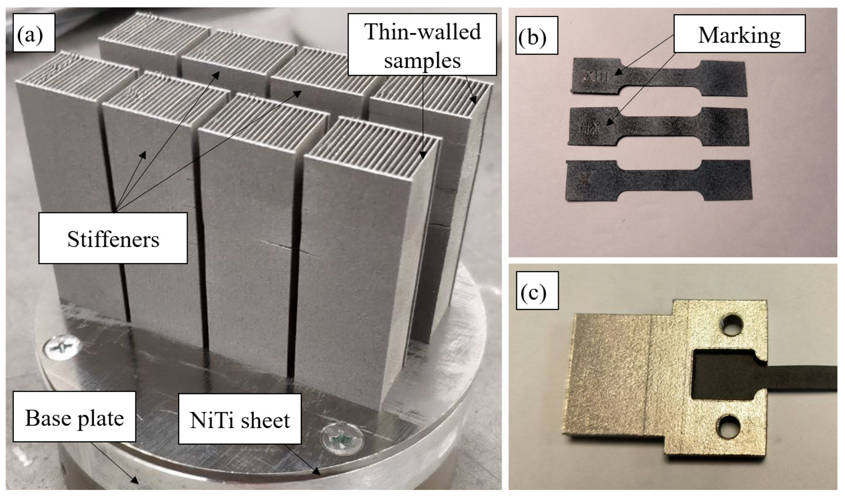
Samples of thin walls for mechanical tests were manufactured via single-track based scanning strategy. All thin walls were placed in cassette assemblies, as shown in Figure 2a. Additional wall stiffeners prevent possible deformations of samples, due to scraper interaction and residual stress release. All samples were marked by a 200 µm deep extrusion of a single surface 3D model (Figure 2b). During the printing of the thin walls, local cracks of stiffeners and burr formation on the top surface of samples were observed. However, the final samples were cut from the cassette; thus, the effect of the abovementioned defects was excluded. It is worth noting that no visible defects were detected in the central part of samples. The sample placed in a manufactured envelope for mechanical tests is shown in Figure 2c.
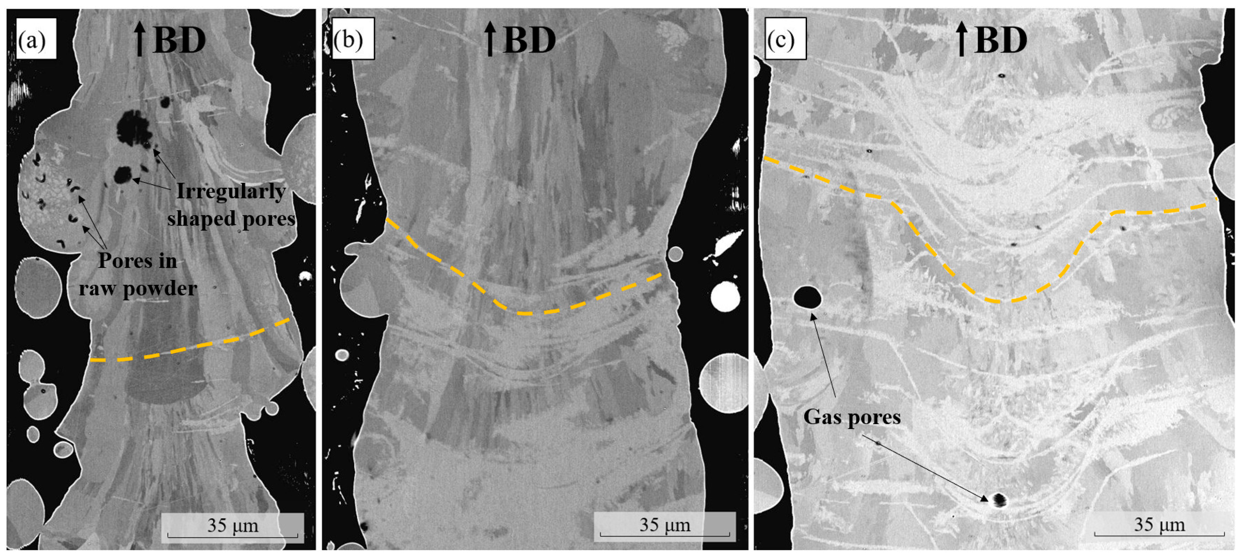
Figure 4 shows the results of microstructural analysis for the representative samples that were manufactured vertically with different laser energy inputs. All thin-walled samples demonstrate an elongated microstructure along the building direction (marked with BD and arrow). It is known that for the laser-based consolidation of material, the transition between columnar and equiaxed structures is dependent on the variation in the thermal gradient and the solidification rate velocity [38]. Consequently, for some process conditions, such a transition should exist; however, a strong texture was observed for all samples despite the wide range variation in the laser power and scanning speed. The observed texture and grain morphology are explained by the limited heat sink for the prescribed type of laser-based manufacturing. In comparison with the volumetric part, when the scanning strategy involves contours and hatching regions, the heat from the melt pool dissipates to the whole volume of the previous layer, which represents solid remelted metal. For the thin-walled part, the heat sink has a single heat transfer direction, which governs crystallization.
The boundaries of solidified melt pools have different morphologies for all three cases. In the case of low LED (linear energy density), the melt pool boundaries are straight and perpendicular to BD (Figure 4a). Such a morphology appeared during the crystallization of a relatively small volume of liquid and the short lifetime of the melt pool, accompanied by low wetting conditions. Some particles were fused to the surfaces of the thin-walled samples but did not melt as far, as the dendritic microstructure in the particles was still present (Figure 4a). Such an effect may lead to the appearance of irregularly shaped pores between the fused particle and remelted volume of the thin wall. For the P100V850 sample (Figure 4b), the melted pool shape corresponds to the conventional conductive mode of melting. The wall thickness fluctuations have a significantly lower period in comparison with the P50V600 sample, due to the multiple remelting of the previous layers. Finally, for high LED (Figure 4c), the morphology of the melt pool is represented with a keyhole shape. As the central part of the keyhole is deeper, the core of the wall will be remelted more times in comparison to the edges. Such features of the melting regime may introduce inhomogeneity to the microstructure, TTs, and phase composition. Interestingly, melted pool boundaries (shown with dashed lines) are more distinct for the P150V500 regime, and the distance between some adjacent boundaries is close to the step of the build platform. An insignificant amount of round gas pores was present for samples consolidated with higher LED.
The samples described were subjected to mechanical uniaxial tensile tests. To investigate the effect of the process parameters (linear energy density) on the mechanical response, the higher strains are of interest. Therefore, static uniaxial tensile tests were performed until fracture at first, to analyze the maximum strain that can be subjected to thin wall samples.
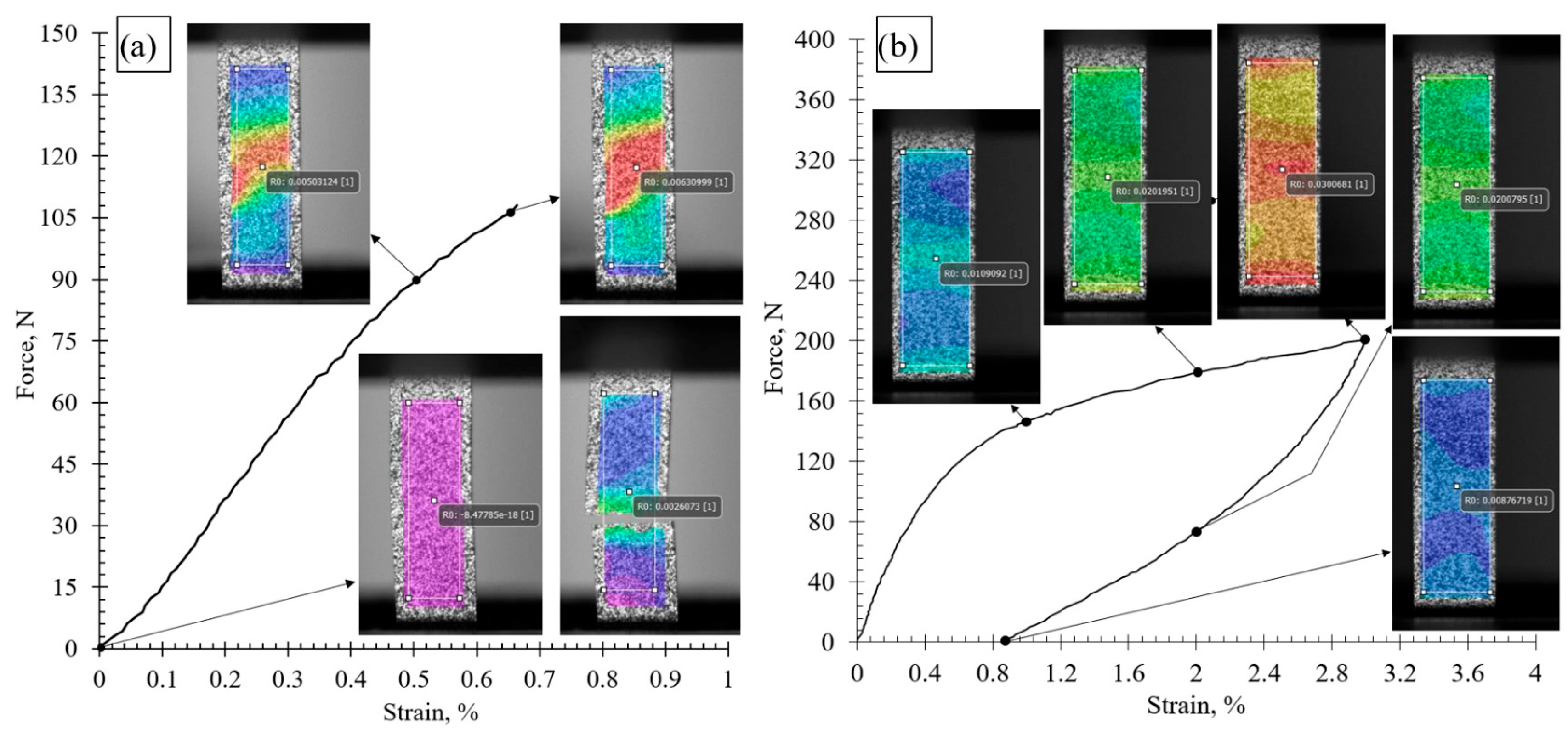
The results of the calculated Lagrangian strain field (ε11), on top of the images from the cameras, are shown in Figure 5. Such fields were analyzed for both tests (until fracture and single cycle), to precisely measure the deformation.
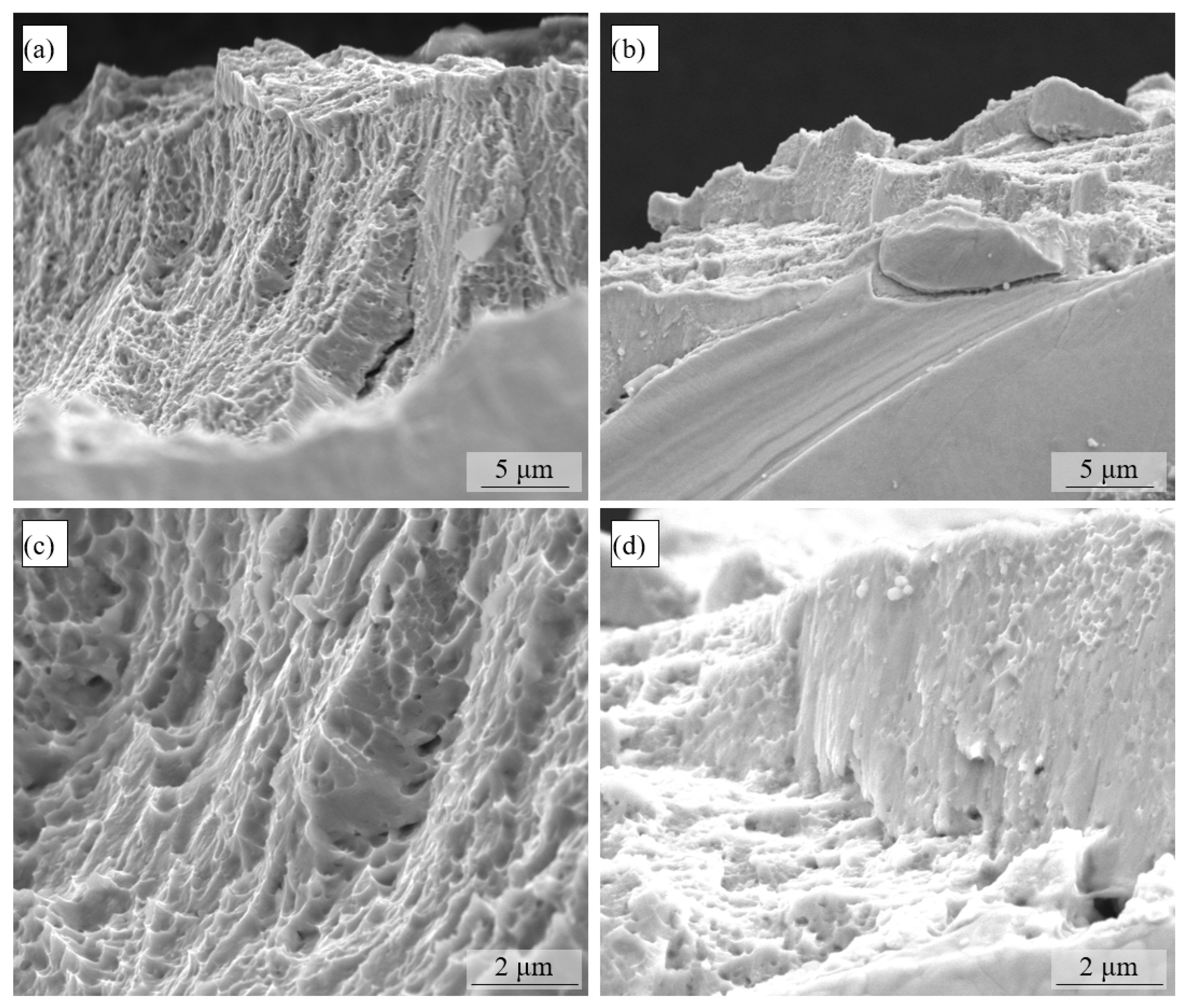
According to the results of static mechanical tests until fracture, all samples can be divided on the low (<1% strain) and high (>2% strain) elongation to fracture cases. Those groups are henceforth referred to as LE (low elongation) and HE (high elongation). After the tests, SEM fractographs were obtained for all samples to determine the fracture’s mechanisms. Typical fracture surfaces for both cases are given in Figure 6.
The representative HE sample, manufactured with the P100V350 regime (Figure 6a,c), demonstrates a fully ductile fracture mechanism with extensive plasticity. The surface is represented by a large number of small dimples (less than 1 µm) and pronounced relief. This morphology indicates fracture due to void growth to coalescence [39]. Ductile fracture is common for NiTi processed in conventional conditions such as cold working or aging [40]. The fracture surface of the LE sample, consolidated with the P100V1350 regime, is demonstrated in Figure 6b,d. The mixed nature of the fracture is observed, including both flat areas of brittle cleavage and some areas of typical ductile dimple fracture (Figure 6b,d). The flat regions’ occurrence during deformation indicates the brittle crack’s initiation and propagation. Any defect in the metal structure serves as the nucleation core of the crack. When a sufficient number of pores is presented in the volume, the coalescence between the nearest is influenced by the crack propagation [39]. Such behavior is considered to be the multiple void interaction mechanism. Thus, it is noted that LE samples demonstrate the predominance of the brittle fracture with low resistance to crack growth.
For the shape memory effect (SME) analysis, one-cycle loading tests were performed. Due to the brittle fracture for some samples, high deformation conditions cannot be achieved in the whole window of the process parameters. Therefore, a maximum strain of 3% was utilized for the one cycle of loading–unloading. The reverse movement of the load cell was switched manually, with precise control of deformation. The actual deformation value was provided by immediate analysis of the last frames captured by DIC.
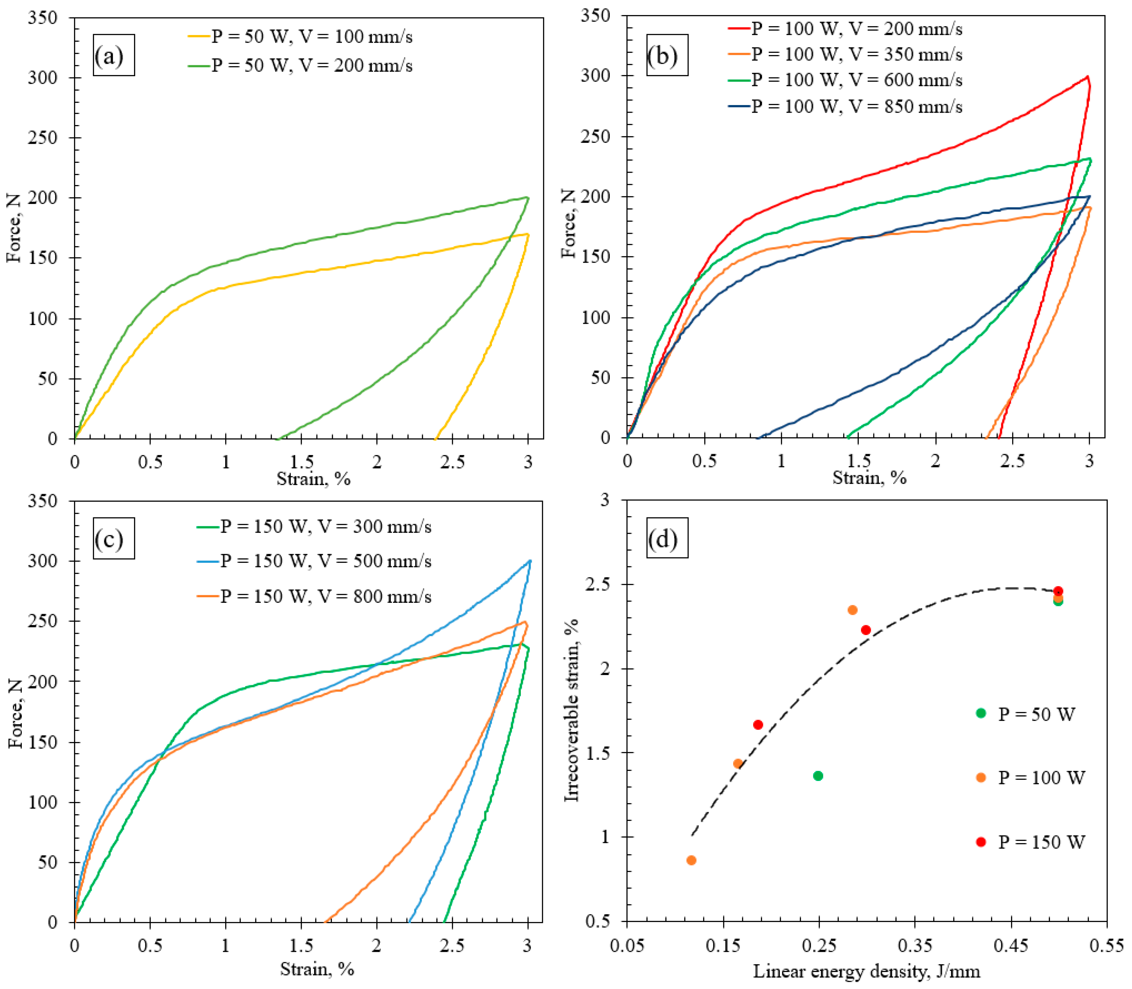
The results of the mechanical tests are presented in Figure 7a–c, with division by laser power. Firstly, various levels of stress plateau (associated with the stress of reorienting martensite by twinning) were achieved. This difference is attributed to a change in the thickness of thin wall-based samples. As far as the thickness is controlled by the linear energy density, this effect is considered to be size-dependent and is not analyzed further. Secondly, a noticeable difference was observed in the reversible/irreversible deformation ratio. Such a response is only connected with material properties and, therefore, can be considered to be an indicator of the technological parameters’ influence.
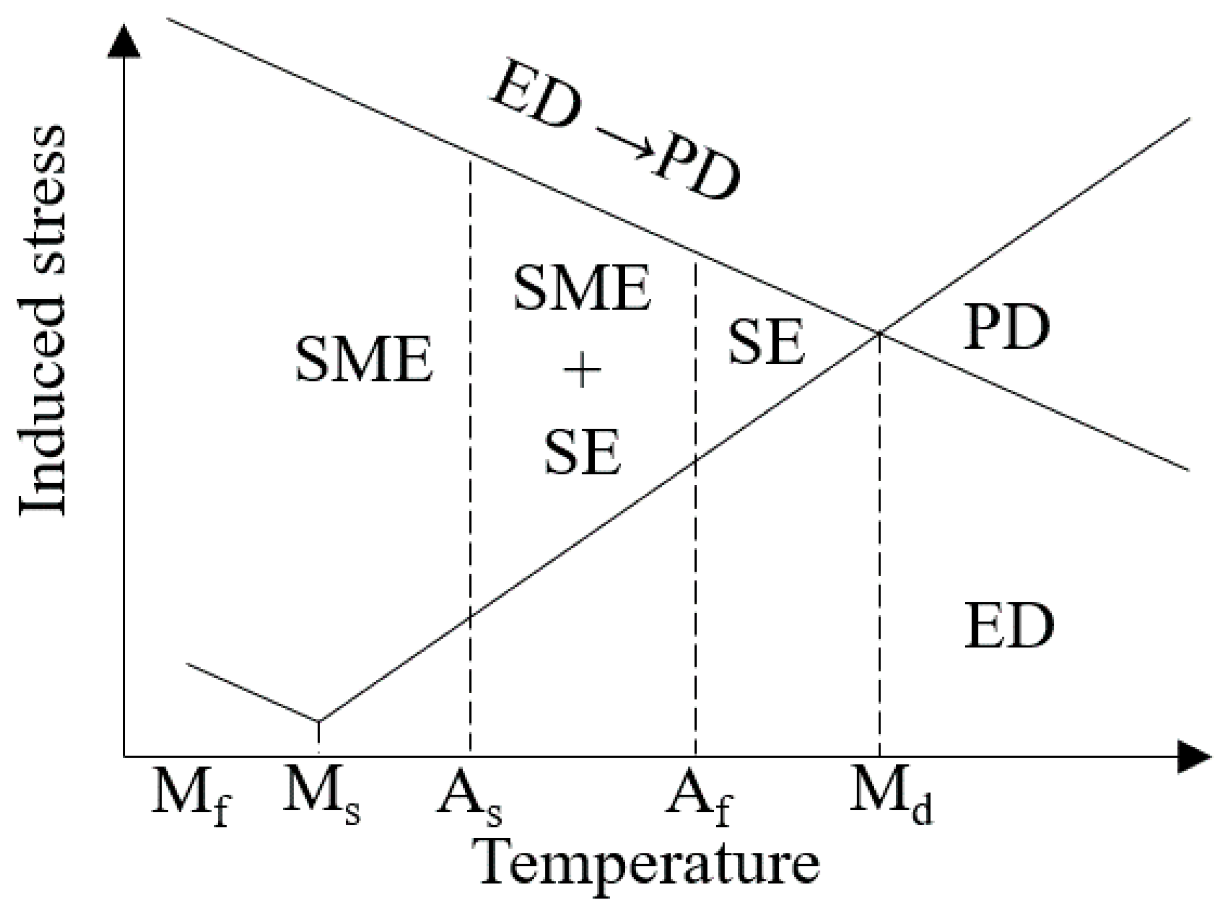
For each group of samples manufactured with different laser power, the dependencies of the irrecoverable strain are visible. Increasing the linear energy density led to growth in the irrecoverable strain, as demonstrated in Figure 7d. After 0.35 J/mm, the value reached its saturation point at ~ 2.5%. This is attributed to the increase in austenite finish temperature, which is above the room temperature at which the test was conducted. Thus, for all samples with LED above 0.35 J/mm, only purely elastic deformation was recovered. According to the segmentation of the mechanical response (Figure 8), the samples manufactured with LED above 0.35 J/mm are considered to be purely in the SME domain, when all samples below the prescribed LED value are in the mixed SME + SE (shape memory effect + superelasticity) region.
Based on the received irrecoverable strain values, the recovery ratio was calculated in accordance with Equation (2). All characteristics describing the mechanical response of the material consolidated with different laser processing conditions are presented in Table 3.
Recovered ratio = ε r e cov e r e d ε t o t a l · 100 %
The highest recovery ratio of 68% was obtained for the sample P100V850. Complete recovery after the deformation is necessary for the correct and stable functioning of the material. In this regard, obtaining a high recovery ratio is considered to be one of the important technological challenges related to the LPBF manufacturing of NiTi. Saedi et al. [41] reported a value of 95% after heat treatment with solutionizing and aging and Haberland et al. received the same level of recovery ratio after multiple loading cycles [42]. Moghaddam et al. reported the highest recovery ratio of 98%, which was achieved without heat treatment [33]. It should be noted that in the present research, the recovery ratio is considered as only one of the indicators to describe the material properties; however, found dependencies from process conditions can be used to maximize the recovery ratio for devices manufactured with high-resolution LPBF.
The sample with the lowest LED of 0.12 J/mm had the minimum irrecoverable strain of 0.86%. It is noted that a further decrease in LED could result in the SE response of samples; however, poor ultimate tensile strength will limit the application of such consolidated parts. In this regard, when the SE response of NiTi is desirable, the optimal LPBF regime presents a compromise between the tendency to increase the energy input to ensure sufficient UTS from one side and decrease LED to reduce irrecoverable strain after cyclic loading.
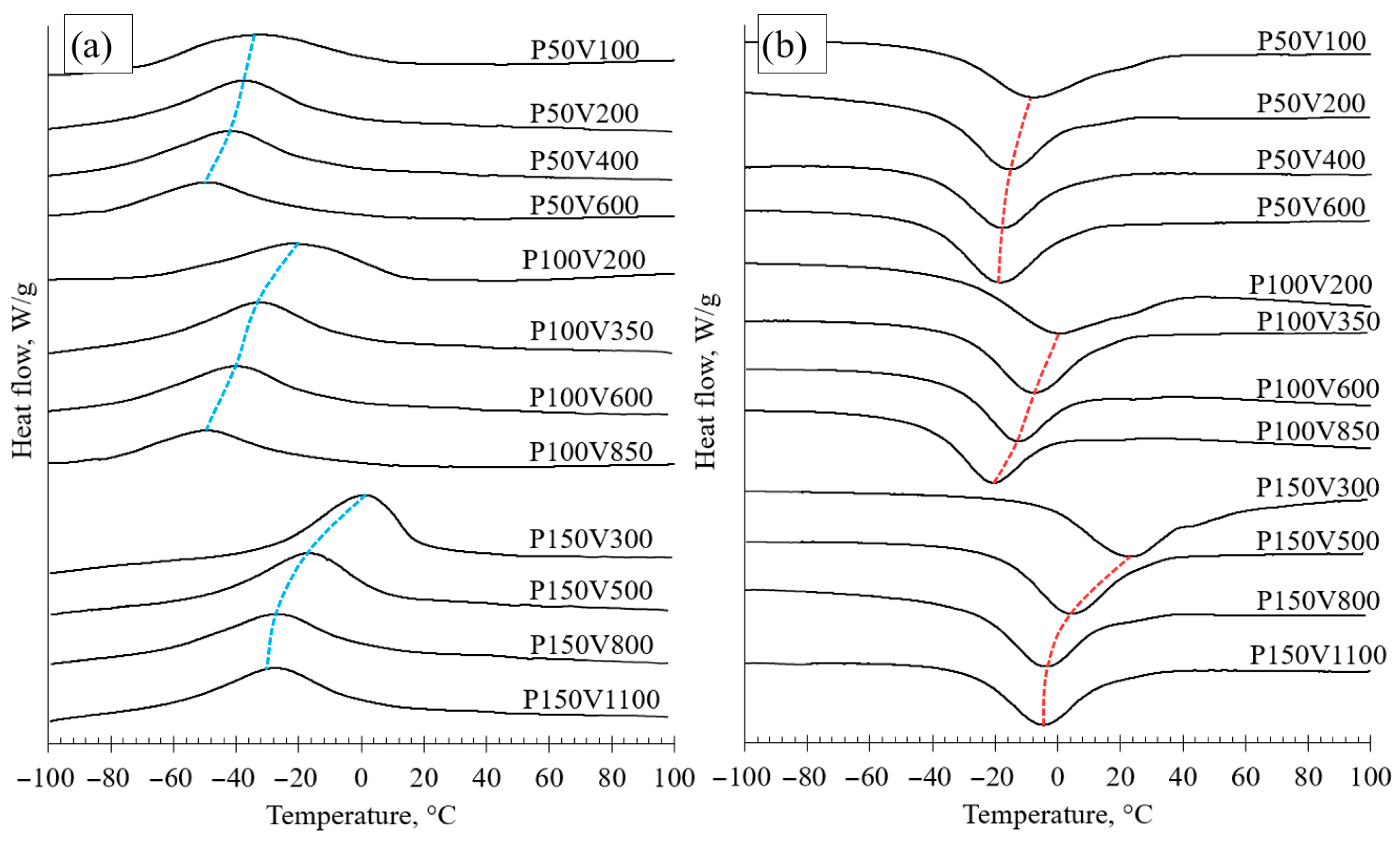
The phase transformation temperatures were determined by using the DSC analysis for both the raw powder and single track-based thin walls. The results of the DSC analysis for all samples are presented in Figure 9. All samples demonstrate a one-step phase transformation, indicating the absence of an intermediate R phase. Both the martensite and austenite peaks are shifting to lower temperatures in the case of equal laser power. In the case of a higher laser power (150 W), the temperatures of the phase transformation experience a higher shift than in the case of a low laser power (50 W). Additionally, the curves of the samples consolidated with 150 W laser power have the most distinct peaks, which is comparable with the effect of the recrystallization and homogenization heat treatments [41].
The exact temperatures for the start, peak, and finish of the austenite and martensite phase transformations are presented in Table 4. The values were determined according to the scheme in Figure 10.
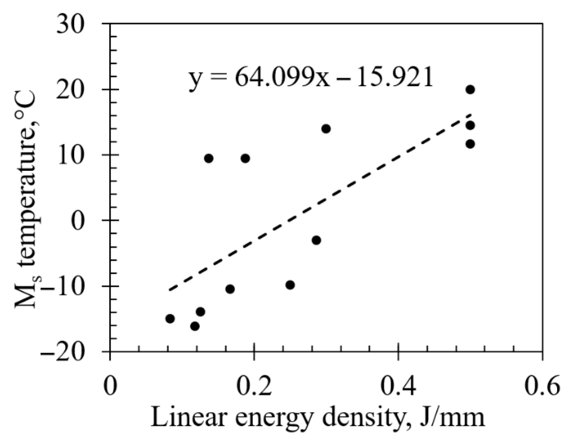
Figure 11 shows the dependence of the onset temperature of the martensitic phase transition from the applied linear energy density to the NiTi powder for consolidation. Most of the experimental data can be expressed with a linear regression model. However, some values of Ms have significantly high discrepancy from the trend. Those values correspond to the samples with the highest power of 150 W. Such deviation can be attributed to the appearance of the secondary mechanism of change in the material properties, i.e., different solidification rates and in situ heat treatment.
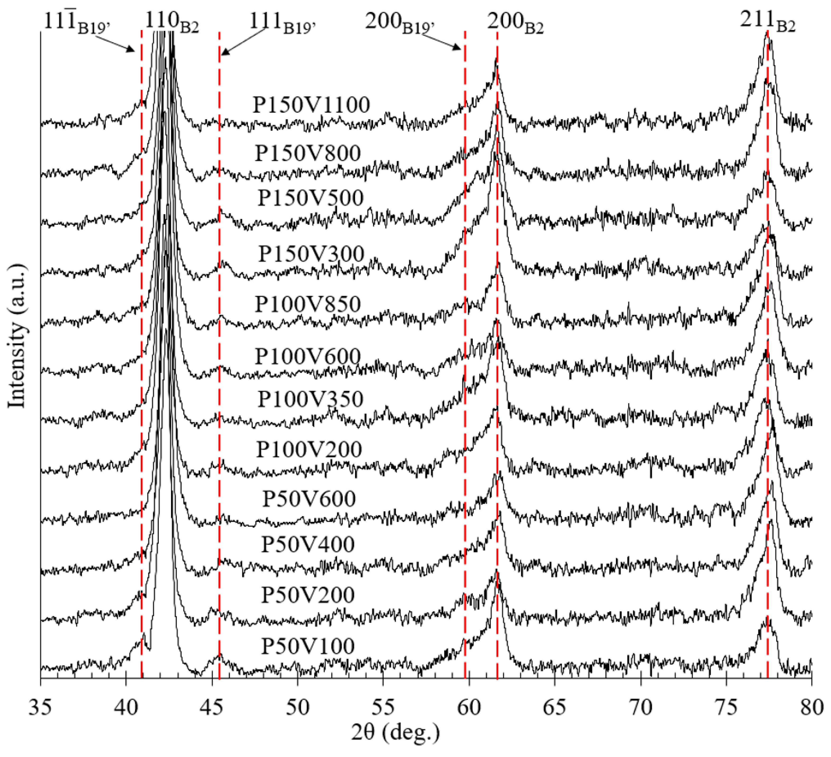
The X-ray diffractograms of the thin walls’ samples, consolidated under different process conditions, are presented in Figure 12. The initial phase composition after LPBF is represented by the high-temperature phase (B2-austenite) and a small (not more than 20%) amount of a low-temperature phase (B19′-martensite), which aligns with DSC, where the room temperature is located at almost the end of the forward martensitic transformation (Figure 9). The prevalence of the high-temperature phase was expected as far as the Ni-rich NiTi powder was used. The B2-phase peak intensity ratio of the thin walls is typical for isotropic NiTi: strong {110}, medium-strong {211}, and medium {200}. The most intense peaks are marked on the XRD spectra with red dashed lines, with the B19′ phase corresponding to the following lattice planes: ( 11 1 ¯ ), (111), and (200). The phase composition slightly changes with linear energy density for each laser power value. These observations correlate with the changes in the temperatures of the martensitic transformation (Table 4). Peaks associated with precipitation by Ni4Ti3 were not observed. However, in the case of extremely high cooling rates that are inherent to the LPBF, two phase evolutions can be considered. The first is related to the complete suppression of the secondary phase formation by the kinetics of the process. The second possible phase evolution refers to the formation of submicron precipitates. However, fine-sized precipitates are complicated to identify through XRD analysis, due to the overlay of peaks of the B2 and B19′ phases, as well as the overall low intensity-to-background ratio [43].
It is worth mentioning that the <100> family is an easy direction for heat transfer and, correspondingly, is an easy growth direction for grains in the BCC system [44]. The strong effect of the crystallographic texture was not observed in XRD patterns with a change in laser energy input. The texture formation with an increasing energy density during LPBF was previously observed for volumetric sample consolidation [45,46]. Thus, the strongly pronounced texture is more likely to appear when many adjacent tracks are introduced to the scanning strategy.
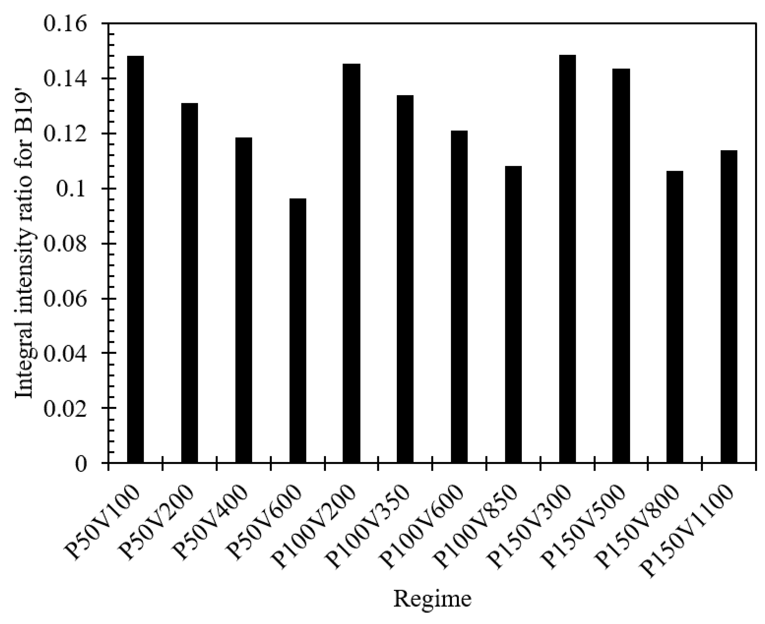
Assuming the material is a two-phase mixture, the phases’ volume fractions can be estimated. For the quantitative evaluation of the ratio between the martensitic and austenitic phases, an evaluation of the relative integrated intensity was performed for the X-ray diagrams [47]. The volume fraction of martensite was calculated by Equation (3) for each plate, consolidated with different regimes. The normalized intensity of each peak by background and width is given by Equation (4).
V B 19 = i = 1 n I 0 B 19 i = 1 n ( I 0 B 19 + I 0 B 2 )
I 0 = ( I p e a k I b a c k ) I b a c k B h k l
where V B 19 is a volume fraction of martensite, I 0 is the normalized intensity, I p e a k is the intensity of the peak, B h k l is the width of the peak at half of the intensity, and I b a c k is the intensity of the background noise.
It should be noted that all peaks (both austenitic and martensitic) from the X-ray diagram (Figure 12) were used for the calculation. Results of the volume fraction evaluation are presented with a histogram in Figure 13. The obtained values depict the ratio between the integral intensity of the peaks corresponding to B19′ and all peaks taken into account. Considering an estimation error, it was concluded that the martensite volume fraction reduces with an increase in scanning speed for each level of laser power. The aforementioned result is related to the issue of receiving the required functional properties in the as-built state.

4. Conclusions

In this work, thin-walled samples were manufactured from pre-alloyed NiTi powder via LPBF in a wide window of laser power and scanning speed. Based on the results of the study, the following conclusions were drawn:
  • Excluding the hatch spacing by means of single track-based thin walls consolidation allowed us to reveal the pure effect of the laser influence on the NiTi functional properties. The samples manufactured with the highest linear energy density (LED) of 0.5 J/mm and highest laser power exhibited a decrease in the characteristic transformation temperatures by 45 °C. This large temperature range provides the basis for controlling functional properties when varying the LPBF process parameters.
  • It was demonstrated that the low values of LED resulted in almost no change in the transformation temperatures (TTs) in comparison with the raw powder. Thus, the process conditions with a minimal influence on the NiTi functional properties are of interest for applications requiring a superelastic (SE) response. However, it was demonstrated that after a significant decrease in LED, poor ultimate strength will limit the performance of such a consolidated part. In this regard, when the SE response of NiTi is desirable, the optimal LPBF regime presents a compromise.
  • Established relationships between the NiTi properties (TTs, irreversible strain, and volume fraction of the martensitic phase) and the LPBF process conditions create a foundation for the production protocols of NiTi with SE behavior, specific SME activation temperature, or multistage SME activation.

Author Contributions

Conceptualization, S.V.C. and E.L.D.; methodology, S.V.C., L.V.F., V.Y.E., D.D.Z., V.O.F., M.V.L., and A.N.U.; validation, S.O.R.; formal analysis, M.V.L., E.L.D., I.V.S., and S.O.R.; investigation, L.V.F., V.Y.E., D.D.Z., V.O.F., and A.N.U.; data curation, V.Y.E., V.O.F., A.N.U., and I.V.S.; writing—original draft preparation, S.V.C.; writing—review and editing, S.V.C. and S.O.R.; visualization, L.V.F. and D.D.Z.; supervision, M.V.L., E.L.D., and I.V.S.; funding acquisition, S.V.C. All authors have read and agreed to the published version of the manuscript.

Funding

This research was funded by the Russian Science Foundation, project 25-29-00954, https://rscf.ru/project/25-29-00954/ (accessed on 19 November 2025).

Data Availability Statement

The raw data supporting the conclusions of this article will be made available by the authors upon request.

Conflicts of Interest

The authors declare no conflicts of interest.

Abbreviations

The following abbreviations are used in this manuscript:
LPBFLaser powder bed fusion
SMAShape memory alloy
SMEShape memory effect
AMAdditive manufacturing
SLMSelective laser melting
TTsTransformation temperatures
PSDParticle size distribution
EDMElectrical discharge machining
DSCDifferential scanning calorimetry
XRDX-ray diffraction
DICDigital image correlation
BDBuilding direction
LEDLinear energy density
LELow elongation
HEHigh elongation
SESuperelasticity
BCCBody-centered cubic

References

  1. Lagoudas, D.C. Shape Memory Alloys; Springer: Boston, MA, USA, 2008. [Google Scholar] [CrossRef]
  2. Alaneme, K.K.; Okotete, E.A. Reconciling viability and cost-effective shape memory alloy options—A review of copper and iron based shape memory metallic systems. Eng. Sci. Technol. Int. J. 2016, 19, 1582–1592. [Google Scholar] [CrossRef]
  3. Patel, S.K.; Behera, B.; Swain, B.; Roshan, R.; Sahoo, D.; Behera, A. A review on NiTi alloys for biomedical applications and their biocompatibility. Mater. Today Proc. 2020, 33, 5548–5551. [Google Scholar] [CrossRef]
  4. Yoneyama, T.; Miyazaki, S. Shape Memory Alloys for Biomedical Applications; Woodhead Publishing Limited: Cambridge, UK, 2009. [Google Scholar] [CrossRef]
  5. Bogue, R. Shape-memory materials: A review of technology and applications. Assem. Autom. 2009, 29, 214–249. [Google Scholar] [CrossRef]
  6. Yahia, L. Shape Memory Implants; Springer: Berlin/Heidelberg, Germany, 2000. [Google Scholar] [CrossRef]
  7. Piquard, R.; D’Acunto, A.; Laheurte, P.; Dudzinski, D. Micro-end milling of NiTi biomedical alloys, burr formation and phase transformation. Precis. Eng. 2014, 38, 356–364. [Google Scholar] [CrossRef]
  8. Kaya, E.; Kaya, İ. A review on machining of NiTi shape memory alloys: The process and post process perspective. Int. J. Adv. Manuf. Technol. 2019, 100, 2045–2087. [Google Scholar] [CrossRef]
  9. Elahinia, M.H.; Hashemi, M.; Tabesh, M.; Bhaduri, S.B. Manufacturing and processing of NiTi implants: A review. Prog. Mater. Sci. 2012, 57, 911–946. [Google Scholar] [CrossRef]
  10. Saha, P.; Datta, S.; Raza, M.S.; Pratihar, D.K. Effects of Heat Input on Weld-Bead Geometry, Surface Chemical Composition, Corrosion Behavior and Thermal Properties of Fiber Laser-Welded Nitinol Shape Memory Alloy. J. Mater. Eng. Perform. 2019, 28, 2754–2763. [Google Scholar] [CrossRef]
  11. Biermann, D.; Kahleyss, F.; Krebs, E.; Upmeier, T. A Study on Micro-Machining Technology for the Machining of NiTi: Five-Axis Micro-Milling and Micro Deep-Hole Drilling. J. Mater. Eng. Perform. 2011, 20, 745–751. [Google Scholar] [CrossRef]
  12. Bram, M.; Ahmad-Khanlou, A.; Heckmann, A.; Fuchs, B.; Buchkremer, H.P.; Stöver, D. Powder metallurgical fabrication processes for NiTi shape memory alloy parts. Mater. Sci. Eng. A 2002, 337, 254–263. [Google Scholar] [CrossRef]
  13. Alvarez, K.; Nakajima, H. Metallic scaffolds for bone regeneration. Materials 2009, 2, 790–832. [Google Scholar] [CrossRef]
  14. Zheng, B.; Trofimov, V.; Yang, Y.; Han, C.; Zeng, Z.; Abbas, S.F.; Li, S.; Lei, L.; Sang, J.; Zhang, J.; et al. Enhancing the dimensional accuracy and manufacturing limits of laser powder bed fusion through dual-laser hybrid additive-subtractive manufacturing. Opt. Laser Technol. 2025, 188, 112947. [Google Scholar] [CrossRef]
  15. Chernyshikhin, S.V.; Pelevin, I.A.; Karimi, F.; Shishkovsky, I.V. The Study on Resolution Factors of LPBF Technology for Manufacturing Superelastic NiTi Endodontic Files. Materials 2022, 15, 6556. [Google Scholar] [CrossRef]
  16. Safaei, K.; Abedi, H.; Nematollahi, M.; Kordizadeh, F.; Dabbaghi, H.; Bayati, P.; Javanbakht, R.; Jahadakbar, A.; Elahinia, M.; Poorganji, B. Additive Manufacturing of NiTi Shape Memory Alloy for Biomedical Applications: Review of the LPBF Process Ecosystem. JOM 2021, 73, 3771–3786. [Google Scholar] [CrossRef]
  17. Dzogbewu, T.C.; du Preez, W.B. Additive manufacturing of Ti-based intermetallic alloys: A review and conceptualization of a next-generation machine. Materials 2021, 14, 4317. [Google Scholar] [CrossRef]
  18. Caprio, L.; Demir, A.G.; Chiari, G.; Previtali, B. Defect-free laser powder bed fusion of Ti–48Al–2Cr–2Nb with a high temperature inductive preheating system. J. Phys. Photonics 2020, 2, 024002. [Google Scholar] [CrossRef]
  19. Shishkovsky, I.; Sherbakof, V. Influence of laser cycling on electro-structural features of nickel-titanium SMA fabricated by LPBF process. Appl. Surf. Sci. 2020, 508, 145278. [Google Scholar] [CrossRef]
  20. Shinkaryov, A.S.; Ozherelkov, D.Y.; Pelevin, I.A.; Eremin, S.A.; Anikin, V.N.; Burmistrov, M.A.; Chernyshikhin, S.V.; Gromov, A.A.; Nalivaiko, A.Y. Laser fusion of aluminum powder coated with diamond particles via selective laser melting: Powder preparation and synthesis description. Coatings 2021, 11, 1219. [Google Scholar] [CrossRef]
  21. Nalivaiko, A.Y.; Ozherelkov, D.Y.; Pelevin, I.A.; Chernyshikhin, S.V.; Medvedev, A.E.; Korshunov, A.V.; Arnautov, A.N.; Gromov, A.A. Comprehensive Study of the 3D Printing of Single Tracks and Cubic Samples by Selective Laser Melting of AlSi10MgCu Alloy. Met. Mater. Int. 2022, 28, 787–801. [Google Scholar] [CrossRef]
  22. Pelevin, I.A.; Burmistrov, M.A.; Ozherelkov, D.Y.; Shinkaryov, A.S.; Chernyshikhin, S.V.; Gromov, A.A.; Nalivaiko, A.Y. Laser powder bed fusion of chromium bronze using recycled powder. Materials 2021, 14, 3644. [Google Scholar] [CrossRef]
  23. Forien, J.B.; Calta, N.P.; DePond, P.J.; Guss, G.M.; Roehling, T.T.; Matthews, M.J. Detecting keyhole pore defects and monitoring process signatures during laser powder bed fusion: A correlation between in situ pyrometry and ex situ X-ray radiography. Addit. Manuf. 2020, 35, 101336. [Google Scholar] [CrossRef]
  24. Zhu, J.N.; Borisov, E.; Liang, X.; Farber, E.; Hermans, M.J.M.; Popovich, V.A. Predictive analytical modelling and experimental validation of processing maps in additive manufacturing of nitinol alloys. Addit. Manuf. 2021, 38, 101802. [Google Scholar] [CrossRef]
  25. Chernyshikhin, S.V.; Firsov, D.G.; Shishkovsky, I.V. Selective Laser Melting of Pre-Alloyed NiTi Powder: Single-Track Study and FE Modeling with Heat Source Calibration. Materials 2021, 14, 7486. [Google Scholar] [CrossRef]
  26. Qi, T.; Zhu, H.; Zhang, H.; Yin, J.; Ke, L.; Zeng, X. Selective laser melting of Al7050 powder: Melting mode transition and comparison of the characteristics between the keyhole and conduction mode. Mater. Des. 2017, 135, 257–266. [Google Scholar] [CrossRef]
  27. Lyu, Z.; Wang, J.; Chen, Y. 4D printing: Interdisciplinary integration of smart materials, structural design, and new functionality. Int. J. Extrem. Manuf. 2023, 5, 032011. [Google Scholar] [CrossRef]
  28. Shishkovsky, I.V.; Scherbakov, V.I.; Kuznetsov, M.V.; Belousova, O.V.; Morozov, Y.G. 4D Laser Printing of Functionally Graded Structures and Items from Mixtures of Powdered Polymers with Functional Micro- and Nanoparticles: An Autoreview. Int. J. Self-Propagating High-Temp. Synth. 2020, 29, 77–86. [Google Scholar] [CrossRef]
  29. Liu, Y.; Wang, Y.; Wu, X.; Shi, J. Nonequilibrium thermodynamic calculation and experimental investigation of an additively manufactured functionally graded material. J. Alloy Compd. 2020, 838, 155322. [Google Scholar] [CrossRef]
  30. Ryklina, E.P.; Polyakova, K.A.; Murygin, S.R.; Komarov, V.S.; Resnina, N.N.; Andreev, V.A. Role of Structural Heredity in Control of Functional and Mechanical Characteristics of Ni-Rich Titanium Nickelide. Phys. Met. Met. 2022, 123, 1226–1233. [Google Scholar] [CrossRef]
  31. Filip, P.; Mazanec, K. On precipitation kinetics in TiNi shape memory alloys. Scr. Mater. 2001, 45, 701–707. [Google Scholar] [CrossRef]
  32. Ma, J.; Franco, B.; Tapia, G.; Karayagiz, K.; Johnson, L.; Liu, J.; Arroyave, R.; Karaman, I.; Elwany, A. Spatial Control of Functional Response in 4D-Printed Active Metallic Structures. Sci. Rep. 2017, 7, 46707. [Google Scholar] [CrossRef] [PubMed]
  33. Moghaddam, S.N.; Saedi, S.; Amerinatanzi, A.; Hinojos, A.; Ramazani, A.; Kundin, J.; Mills, M.J.; Karaca, H.; Elahinia, M. Achieving superelasticity in additively manufactured NiTi in compression without post-process heat treatment. Sci. Rep. 2019, 9, 41. [Google Scholar] [CrossRef]
  34. Chernyshikhin, S.V.; Panov, D.V.; Van Tuan, T.; Ozherelkov, D.Y.; Sheremetyev, V.A.; Shishkovsky, I.V. Laser Polishing of Nickel-Titanium Shape Memory Alloy Produced via Laser Powder Bed Fusion. Met. Mater. Int. 2023, 29, 3024–3038. [Google Scholar] [CrossRef]
  35. Chernyshikhin, S.V.; Mahato, B.; Shiverskii, A.V.; Pelevin, I.A.; Dubinin, O.N.; Egorov, V.Y.; Abaimov, S.G.; Shishkovsky, I.V. In-plane measurements and computational fluid dynamics prediction of permeability for biocompatible NiTi gyroid scaffolds fabricated via laser powder bed fusion. Int. J. Bioprinting 2023, 10, 0119. [Google Scholar] [CrossRef]
  36. ASTM B527-20; Standard Test Method for Tap Density of Metal Powders and Compounds. ASTM International: West Conshohocken, PA, USA, 2020.
  37. Sitepu, H.; Schmahl, W.W.; Khalil Allafi, J.; Eggeler, G.F.; Reinecke, T.; Brokmeier, H.G.; Tovar, M.; Többens, D.M. Texture and Quantitative Phase Analysis of Aged Ni-Rich NiTi using X-Ray and Neutron Diffractions. Mater. Sci. Forum 2002, 394–395, 237–240. [Google Scholar] [CrossRef]
  38. Collins, P.C.; Brice, D.A.; Samimi, P.; Ghamarian, I.; Fraser, H.L. Microstructural Control of Additively Manufactured Metallic Materials. Annu. Rev. Mater. Res. 2016, 46, 63–91. [Google Scholar] [CrossRef]
  39. Pineau, A.; Benzerga, A.A.; Pardoen, T. Failure of metals I: Brittle and ductile fracture. Acta Mater. 2016, 107, 424–483. [Google Scholar] [CrossRef]
  40. Dayananda, G.N.; Rao, M.S. Effect of strain rate on properties of superelastic NiTi thin wires. Mater. Sci. Eng. A 2008, 486, 96–103. [Google Scholar] [CrossRef]
  41. Saedi, S.; Turabi, A.S.; Andani, T.M.; Haberland, C.; Karaca, H.; Elahinia, M. The influence of heat treatment on the thermomechanical response of Ni-rich NiTi alloys manufactured by selective laser melting. J. Alloy Compd. 2016, 677, 204–210. [Google Scholar] [CrossRef]
  42. Haberland, C.; Elahinia, M.; Walker, J.M.; Meier, H.; Frenzel, J. On the development of high quality NiTi shape memory and pseudoelastic parts by additive manufacturing. Smart Mater. Struct. 2014, 23, 104002. [Google Scholar] [CrossRef]
  43. Prokofiev, E.A.; Burow, J.A.; Payton, E.J.; Zarnetta, R.; Frenzel, J.; Gunderov, D.V.; Valiev, R.Z.; Eggeler, G. Suppression of Ni4Ti3 Precipitation by Grain Size Refinement in Ni-Rich NiTi Shape Memory Alloys. Adv. Eng. Mater. 2010, 12, 747–753. [Google Scholar] [CrossRef]
  44. Kou, S. Welding Metallurgy; John Wiley & Sons, Inc.: Hoboken, NJ, USA, 1987. [Google Scholar]
  45. Kreitcberg, A.; Sheremetyev, V.; Tsaturyants, M.; Prokoshkin, S.; Brailovski, V. Optimization of Post-processing Annealing Conditions of the Laser Powder Bed-Fused Ti–18Zr–14Nb Shape Memory Alloy: Structure and Functional Properties. Shape Mem. Superelasticity 2019, 5, 172–181. [Google Scholar] [CrossRef]
  46. Brailovski, V.; Kalinicheva, V.; Letenneur, M.; Lukashevich, K.; Sheremetyev, V.; Prokoshkin, S. Control of Density and Grain Structure of a Laser Powder Bed-Fused Superelastic Ti-18Zr-14Nb Alloy: Simulation-Driven Process Mapping. Metals 2020, 10, 1697. [Google Scholar] [CrossRef]
  47. Gunderov, D.; Kim, K.; Gunderova, S.; Churakova, A.; Lebedev, Y.; Nafikov, R.; Derkach, M.; Lukashevich, K.; Sheremetyev, V.; Prokoshkin, S. Effect of High-Pressure Torsion and Annealing on the Structure, Phase Composition, and Microhardness of the Ti-18Zr-15Nb (at. %) Alloy. Materials 2023, 16, 1754. [Google Scholar] [CrossRef] [PubMed]
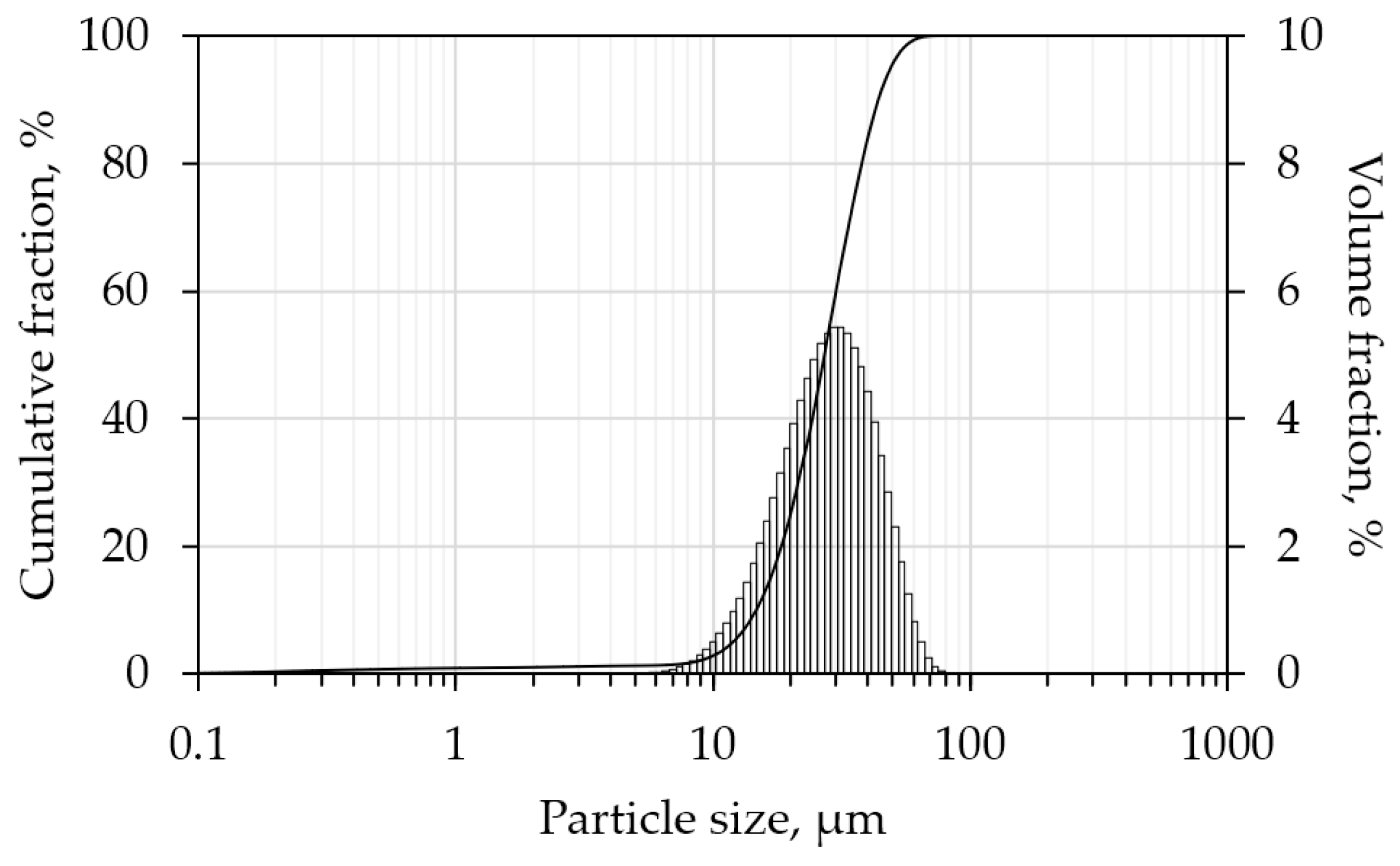
Figure 1. Particle size distribution of NiTi raw powder.
Jmmp 09 00385 g001
Figure 2. NiTi thin-walled samples: (a) as-built cassette assemblies of thin walls in z orientation on the building platform with NiTi substrate, (b) dog-bone specimens after EDM cutting with speckle pattern, and (c) manufactured mounting envelope for mechanical tests.
Jmmp 09 00385 g002
Figure 3. Drawing of (a) flat dog-bone sample, and (b) mounting for mechanical tests.
Jmmp 09 00385 g003
Figure 4. SEM images of thin wall samples’ microstructure for the following: (a) P50V600, (b) P100V850, and (c) P150V500. Remelting boundaries are shown with dashed lines.
Jmmp 09 00385 g004
Figure 5. Stress–strain curves with corresponding DIC images for sample (a) P50V600 [until fracture] and (b) P100V850 [single cycle loop].
Jmmp 09 00385 g005
Figure 6. SEM images of fracture surface for samples (a,c) P100V350 and (b,d) P100V1350 with magnification of (a,b) 10k and (c,d) 30k.
Jmmp 09 00385 g006
Figure 7. Results of mechanical tests: force-strain curves for a single cycle of loading for samples manufactured with a laser power of (a) 50 W, (b) 100 W, (c) 150 W, and (d) dependence of the irrecoverable strain on the linear energy density for all samples.
Jmmp 09 00385 g007
Figure 8. Schematic diagram of the thermomechanical response of NiTi depending on the stress-temperature conditions.
Jmmp 09 00385 g008
Figure 9. DSC curves of as-built samples with different LPBF process parameters (a) cooling and (b) heating.
Jmmp 09 00385 g009
Figure 10. Typical DSC response of heating/cooling cycle of SMA with marked characteristic temperatures.
Jmmp 09 00385 g010
Figure 11. Dependence of the Ms temperature on the linear energy density.
Jmmp 09 00385 g011
Figure 12. XRD patterns for as-built samples, consolidated under different process conditions.
Jmmp 09 00385 g012
Figure 13. Change in integral intensity ratio for B19′, in relation to the consolidation regimes.
Jmmp 09 00385 g013
Table 1. NiTi powder physical properties.
Powder PropertyUnitsValue
Nickel contentwt.%55.9
Oxygen contentwt.%0.03
Hall flows/50 g18.5
Tap densityg/cm33.92
Relative tap density%60.7
d50μm27.8
Table 2. LPBF process conditions.
P, WV, mm/sEl, J/mm
501000.50
502000.25
1002000.50
1003500.29
1006000.17
1008500.12
1503000.50
1505000.30
1508000.19
Table 3. Functional properties of NiTi thin wall samples.
P, WV, mm/sEl, J/mmεrec, %εirrec, %Recovery Ratio, %
501000.500.662.3422
502000.251.641.3655
1002000.500.542.4618
1003500.290.562.4419
1006000.171.501.5050
1008500.122.050.9568
1503000.500.462.5415
1505000.300.782.2226
1508000.191.271.7342
Table 4. Characteristic temperatures of austenite and martensite transformations.
Sample Name
(LPBF Regime)
Transformation Temperatures (°C)
MsMpMfAsApAfΔT
P50V10011.7−37.7−71.1−36.2−9.126.528.6
P50V200−9.8−38.5−36.5−36.6−15.45.723.1
P50V400−13.9−41.5−76−40.4−17.45.924.1
P50V600−15−48.8−80.7−40.3−18.85.130
P100V20014.5−17.6−64.5−31.5−241.215.6
P100V350−3−33−62.3−39.2−7.915.325.1
P100V600−10.4−40.5−69.9−33.1−136.827.5
P100V850−16.1−49.7−81.7−42.3−20.9−1.828.8
P150V300201−31−4.5234322
P150V50014−17−58−19.5429.521
P150V8009.5−27−76−29.5−42023
P150V11009.5−27.5−71−28.9−5.517.122
Disclaimer/Publisher’s Note: The statements, opinions and data contained in all publications are solely those of the individual author(s) and contributor(s) and not of MDPI and/or the editor(s). MDPI and/or the editor(s) disclaim responsibility for any injury to people or property resulting from any ideas, methods, instructions or products referred to in the content.