Article

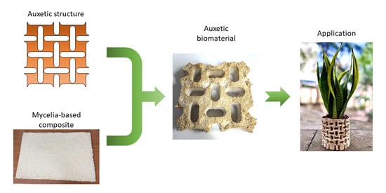
Auxetic Systems Fabricated Using Mycelia-Based Composites

1
Metamaterials Unit, Faculty of Science, University of Malta, MSD2080 Msida, Malta
2
Physiology & Biochemistry, Faculty of Medicine & Surgery, University of Malta, MSD2080 Msida, Malta
3
Centre for Molecular Medicine, Biomedical Sciences Building, University of Malta, MSD2080 Msida, Malta
4
Chemistry Department, Faculty of Science, University of Malta, MSD2080 Msida, Malta
*
Author to whom correspondence should be addressed.
J. Manuf. Mater. Process. 2025, 9(11), 353; https://doi.org/10.3390/jmmp9110353
Submission received: 20 August 2025 / Revised: 16 October 2025 / Accepted: 18 October 2025 / Published: 28 October 2025

Abstract

In an era of increasingly problematic global waste management, innovative materials can hold the key to a circular economy. Within such a context, this work aimed at manufacturing, potentially for the first time, auxetic material (i.e., materials with a negative Poisson’s ratio) using mycelia-based composites (i.e., materials made by growing fungi on a biodegradable substrate). The fabrication of the auxetic biomaterials was undertaken using both direct growth methods in purposely designed molds and through subtractive manufacturing of commercially available mycelia panels. In the former case, various substrates were employed, differing in sawdust granulation and nutrient content. Furthermore, enhancements in the form of scaffolds and hay were considered with the aim of improving the cohesion and elastic properties of the end product. Mechanical testing of the samples produced showed that both manufacturing methods can produce structures capable of exhibiting a negative Poisson’s ratio. At the same time, the intrinsic brittle nature of mycelia-based composites limits the compactness and cohesion of the end products. In this context, the different methodologies employed to improve these properties yielded some promising results. Thus, while this work showed that indeed auxetic biomaterials can be fabricated, the manufacturing methods still require further improvement to produce better-performing specimens.

Graphical Abstract

1. Introduction

Global yearly municipal solid waste (which includes only residential, commercial, and institutional waste) currently exceeds two billion tons [1]. Of this, only about 62% is disposed of in a controlled manner, with almost half of this (corresponding to 30% of the global total) ending up in landfills [1]. Of the rest, around a third of the actively managed waste (corresponding to 19% of the global total) is recycled, while some 21% (corresponding to 13% of the global total) is used to generate energy [1]. In particular, recent estimates indicate that out of the 359 million tons of plastics manufactured annually, more than half ends up in landfills with only around 19.5% being recycled [2]. The extent and poor management of waste can lead to environmental pollution and contribute to climate change [1,3,4].
The amount of waste generated is expected to continue increasing in the near future [5]. At the same time, the natural available resources are finite, with their availability being on the decrease [6,7]. This makes the adoption of sustainable strategies for waste management an urgent need, leading many countries to shift towards a circular economy. The concept of a circular economy goes beyond the simple notion of recycling items when they are being disposed of. Instead, products are designed from the outset with the reuse of the materials at the end of their life cycle in mind [5,6,7,8,9]. The idea is to maximize the length of time a resource can be utilized and concurrently minimize waste.
One way of moving towards a circular economy is to replace existing products with bio-based materials that are synthesized from living organisms. Thus, at the end of their life cycle, the material should, in principle, be completely compostable, leaving minimal residual waste, if any. In this context, one of the most commercially successful large-scale materials made from living organisms, which is currently available, is based on fungi [10]. The production process involves growing fungi on a substrate, generally consisting of organic waste, such as sawdust or hay, leading to the formation of what are known as mycelia-based composites (MBCs) [11]. The formation of MBCs is made possible thanks to the mycelium, a complex network of thin filaments known as hyphae, which constitutes the vegetative structure of fungi. This biologically active network decomposes and binds organic materials using mechanical forces and hydrolytic enzymes, essentially acting as a natural adhesive [12,13,14,15]. The growth process is stopped at some point through heating or dehydration [11,16]. Composites produced this way generally have mechanical and physical properties comparable to expanded polystyrene and similar foams [11,17,18,19,20]. This makes them ideal to replace fossil-fuel-based plastics and foams in applications such as packaging [13] and acoustic insulation [21,22].
Another innovative type of material that has increasingly attracted attention is one that has a negative Poisson’s ratio [23,24,25,26,27,28,29,30,31,32,33,34,35,36,37,38,39,40,41,42,43,44]. Systems with this property are usually referred to as auxetic [26]. They possess the unusual ability of contracting (expanding) laterally when uniaxially compressed (stretched). This behavior allows them to show enhanced capabilities compared to their conventional counterparts, including, amongst others, increased impact resistance [27], energy absorption [28], vibration control [29,30,31], and sound absorption [23,24,25]. These properties of auxetic systems are in common with those of MBCs.
The overlap of desirable properties observable in fungi-based biomaterial and auxetics suggests that combining the two can lead to products that would be able to outperform conventional materials while at the same time being biodegradable and environmentally friendly. Essentially, the introduction of auxetic patterns in the MBCs is expected to enhance the already good acoustic and impact absorption attributes of the fungi-based biomaterial. It can also improve other aspects, such as producing lighter-weight materials compared to the original fungi-based biomaterial, given the need to introduce the voids required for the deformation. Furthermore, the end product can also lead to innovative applications, as will be discussed in this work. Notwithstanding the potential advantages in combining the auxetic and MBCs, to the knowledge of the authors, it does not seem that any investigation in this direction has been reported in the literature thus far.
On the good side, fabrication of auxetic biomaterials is facilitated by the fact that many auxetic structures can be manufactured through the use of perforations, both in 2D [45,46,47], as well as in 3D [48]. The perforations themselves can thus serve as blueprints for the creation of molds where the mycelia can be grown.
With these considerations, this work is aimed at investigating, possibly for the first time, the viability of manufacturing auxetic systems using MBCs as the base material. In the main, this was undertaken by growing mycelia in purposely designed molds. Furthermore, subtractive manufacturing was also used to fabricate auxetic biomaterials from readily available mycelia panels. The results obtained indicate that the MBCs manufactured can indeed exhibit a negative Poisson’s ratio. At the same time, the brittle nature of the composites poses a limit on their performance. In order to counteract this, various enhancements were considered. These were shown to exhibit different degrees of success in improving the behavior of the composites.

2. Materials and Methods

2.1. Design and Fabrication of the Molds

The first step taken in the manufacturing of auxetic systems using MBCs was to consider which of the structures that exhibit a negative Poisson’s ratio are best suited to accommodate the growth of the mycelia. Generally speaking, there are three major designs that lead to auxetic behavior: these being chiral structures [49,50,51,52,53,54], re-entrant cells [55,56,57,58,59], and rotating rigid units [60,61,62,63] (Figure 1).
Chiral systems consist of nodes linked together in some way through ligaments (Figure 1a). Applying stresses along the sides will induce a moment at the nodes, making them rotate. In turn, this will cause the ligaments to bend, changing the dimension of the structure. On the other hand, re-entrant cells are characterized by arrow-shaped ligaments (Figure 1b). Under loading, the force exerted causes a change in the angle of the V-shaped tip. This results in an overall change in the size of the system. Regarding rigid units, as their name implies, these consist of rigid elements connected at corners or edges (Figure 1c). When loaded, the rigid parts are induced to rotate relative to one another with the joints acting as hinges, leading to an auxetic behavior. In 2D, the shapes are usually polygonal or derived from these in some way. It should be stressed that the above represent the ideal behavior of the structure and, in practice, other deformation mechanisms can act.
A review of these three types of systems immediately indicates that chiral and re-entrant systems require relatively thin ligament elements to achieve a negative Poisson’s ratio. This is not ideal for MBCs for two reasons. The first is that it allows very little space for the growth of the mycelia, most likely resulting in a relatively weak structure. Furthermore, the bending of the ligaments made of MBCs can easily lead to their failure.
Comparatively speaking, rigid units are much less porous than chiral and re-entrant systems, providing significantly more space where the mycelia can be grown and allowed to create a compact structure. The major foreseeable downside to rigid units is represented by the relative high stresses that can occur at the joints. However, these can be mitigated by rounding the corners at the joints, for example. Various designs can be used to do this, as illustrated in Figure 1c.
Based on these considerations, the rigid unit mechanism, with rounding at the corners, appeared to be the most promising to fabricate auxetic systems with MBCs as the base material. For this purpose, the rotating squares system [60,63,71] was chosen because of its simplicity. The shape of the voids (or perforations) between the rigid units was selected to have a stadium design. This type of shape has the added advantage of being relatively easy to produce using subtractive manufacturing, potentially providing an alternative pathway for the fabrication of the structure. The critical component then was constituted by the choice of the dimensions, particularly that of the minimum distance between the holes (labeled as s in Figure 1c). It is known that if this distance is too large, it would suppress the auxetic behavior [72]. On the other hand, if it is too small, then it would create a weak point in the base material. A compromise choice had to be found in the investigations that followed.
Once the auxetic structure to utilize was identified, the next step was to create the corresponding mold. The minimum distance s (Figure 1(ciii)) between the perforations was set to 5 mm. This measurement was chosen as a trade-off between allowing sufficient space for the mycelia to grow while at the same time preserving the auxetic mechanism. As for the perforations, the straight edge of the stadium was chosen to have a length a = 10 mm while the radius of the semicircle was selected to be r = 5 mm (Figure 1(ciii)). Essentially, this meant that the central rectangular part of the stadium shape was, in fact, a square. It followed that the resultant unit cell had a squarish layout with a side length of 40 mm. Then, based on the printer dimensions and previous experiment experience, the mold for this initial investigation was designed to accommodate 2 × 2 unit cells.
Once the dimensions were set, the mold could be constructed with ease of demolding in mind. For this purpose, a modular design was adopted consisting of the base and top (or lid) containing the stadium perforations, the four side walls (with opposite sides having the same layout), and the inserts that prevent the composite from closing the holes (see Figure 2). The internal dimensions of the base were 80 × 80 mm. Considering the 5 mm thickness of the side walls, the overall footprint of the mold was 90 × 90 mm. The internal height was chosen to be 2 cm, which is similar to the thickness of the mycelia panels that can be found on sale. The required parts were hence designed using the computer-aided design (CAD) software Autodesk Inventor Professional and then printed using a Bambu Lab X1-Carbon 3D printer with biodegradable PLA basic filament (SKU: A00-W1-1.75) as printing material. As can be noted from Figure 2f, the base, lid, and side walls were fixed together using eight bolts with fly nuts. On the other hand, the inserts were held in position using a push-fit mechanism.
Furthermore, as discussed by Elsacker et al. [73], adequate airflow within the substrate is important to maintain a controlled micro-climate during the incubation process of the mycelia and foster growth. Thus, in order to ensure proper ventilation of the substrate throughout the mold, holes were included in the design of the inserts. As illustrated in Figure 2d, these consisted of four sets of five circular holes, two of which were along the centerline on each of the flat surfaces, and the other two were along the centerline of the curved surfaces. The diameter of the holes was set to 1.5 mm.
The molds prepared were then to be filled using substrate and mycelia mixtures so as to produce composites, the shape of which is illustrated in Figure 3. The way this was done is detailed in the following sections.

2.2. Procedure Followed for Auxetic MBCs Grown on an In-House Substrate Mix

2.2.1. Substrate and Inoculum Preparation

After carrying out an extensive literature review and initial testing, Trametes versicolor was chosen as the fungus to manufacture the composites. Major considerations for the selection included the availability of the fungus, established growth potential, known best practices to enhance growth, ability to show suitable mechanical properties, and absence of toxicity. This was then procured in the form of grain spawn from the MRCA Mushroom Research Center (Innsbruck, Austria).
The other components of the substrate on which the fungus was to be grown, namely gypsum (calcium sulfate), beech wood sawdust (having a granulation of 0.75–3 mm), and wheat bran, were all sourced from the same supplier as the grain spawn. Furthermore, in order to be able to produce more compact composites, the beech wood sawdust was refined to a particle size of less than 180 μm using an electric grain miller (Lejieyin, Model 1000A; UK). The process involved four milling cycles of 1 min each, with a 3 min cooling interval in between. The milled sawdust was subsequently sieved using a Retsch AS 200 sieve shaker that was equipped with a test sieve (ISO 3310-1, body: 316L stainless steel, mesh: stainless steel, dimensions: 200 mm × 50 mm; Germany).
For the experiments, five different substrates were considered, namely Si with i = 1, …, 5. The composition of these per unit amount (1 kg) of substrate as expressed in ratios is given in Table 1. The composition of S1 was derived based on information gathered from literature [74,75,76] and preliminary trials. The main difference is that a finer granulation sawdust was employed. Finer granulation of sawdust was meant to provide more compactness to the composite. In terms of the investigation, S1 was meant to act as the base or reference substrate. As for the compositions S2, S3, and S4, these had higher wheat bran, gypsum, or both compared to S1, as can be noted from the amounts (in terms of mass per kilogram). This was done at the expense of the sawdust content. The intent was to determine if performance was dependent on nutrient composition. Considering S5, in this case, the regular sawdust was meant to provide a concentrated source of nutrition, much like wood chips are generally used [74].
Substrate preparation involved mixing the ingredients in batches of 300 g and then filling the autoclavable polypropylene bags. The substrates were sterilized using an autoclave at 125 °C for 35 min and cooled overnight before inoculation.

2.2.2. Scaffoldings and Substrate Enhancements

In an attempt to improve the compactness and flexibility of the MBC produced, the use of scaffolds and substrate enhancements was considered. The former consisted of planar grids (Figure 4) that were to be inserted in the substrate with the aim of enhancing the binding of the resultant MBC. Two different grid designs were utilized, both of which were based on the same auxetic pattern employed for the molds, but each characterized by its own distinct geometric layouts (Figure 4). The first configuration (referred to as the S-pattern hereafter) was developed by superposing stadium-shaped perforations onto a regular square grid, having the grid line widths wS and an out-of-plane height hS both equal to 0.5 mm, while the holes had a side length lS = 2 mm. As for the stadium-shaped perforations, these were slightly larger than those used for the mold so as to ensure proper alignment with both the mold and the inserts. The values of a and r were 10.4 mm and 5.2 mm, respectively. As a consequence, the minimum distance between the stadium-shaped perforations was sS = 4.4 mm.
The second configuration (referred to as the C-pattern in what follows) was derived by drawing an outline of width wC,O = 1 mm and out-of-plane height hC,O = 3 mm around the stadium-shaped perforations. Similarly to the S-pattern, the values of a and r were taken to be larger than those of the mold, namely 10.4 mm and 6.9 mm, respectively. In this way, the minimum distance between the perforations was sC = wC,O =1 mm. The outline was then superposed on the same square grid used for the S-pattern to fill in the space created by the intersection of the four semicircles. The square grid had the same dimensions as those used for the S-pattern, namely square holes of side length lC,G = 2 mm, with the width wC,G, and out-of-plane height hC,G being both equal to 0.5 mm. Considering the design of the C-pattern, the use of the relatively thick outline was expected to act as a structural reinforcement. Hence, the C-pattern was expected to provide greater rigidity compared to that offered by the S-pattern.
These scaffolds were designed using the CAD software Autodesk Inventor Professional. They were then manufactured with a Bambu lab X1-carbon 3D printer (China) using the same biodegradable PLA employed for the molds (Figure 4).
An alternative way of enhancing the compactness of the MBC was to incorporate hay. Generally speaking, hay or straw can be used as a substrate in itself [77,78,79,80]. However, in this case, it was used with the aim of supplying fiber. Essentially, the strands of hay can extend a relatively large distance compared to sawdust, thus helping the binding of the material across broad stretches by the mycelia network. Furthermore, hay is relatively flexible, a property that was expected to help with the bending capabilities of the final product. About 100 g of this was sourced locally. It was then sterilized using the same methodology adopted for the in-house substrate. The hay was then cut into pieces small enough to fit into the mold before being added to the substrate while filling these containers.

2.2.3. Specimen Preparation

The inoculation of the substrate and the filling of the molds were carried out under sterile conditions using a laminar flow hood. All molds were sterilized with 70% alcohol prior to use. Subsequently, a layer of tape was added on the outer side of the bottom surface to ensure that the stadium perforation inserts remained fixed during the filling process and growth period.
At this stage, to prevent the composite from adhering to its container during the growth phase, wax paper was placed between the sample mixture and the mold. The wax paper for the base and top sections was laser-cut to produce the auxetic pattern using an L8 Laser Engraver (China). On the other hand, those employed for the sidewalls were manually cut and secured using adhesive tape.
Once the containers were ready, a total of 14 specimens were prepared, with the details of their compositions being given in Table 2. The procedure to fill the molds depended on the type of additional reinforcement used as follows:
  • Inclusion of S-pattern: Three grids were placed in the mold, positioned between layers of approximately 5 g, 10 g, 10 g, and 5 g of inoculated substrate.
  • Inclusion of C-pattern: Only two grids were placed in the mold, positioned between 10 g layers of the inoculated substrate, as the C-pattern scaffolding was thicker than the S-pattern one.
  • Inclusion of fiber reinforcements: Two layers of hay, each containing approximately 0.2 g, were distributed like a mesh between 10 g layers of the inoculated substrate.
Table 2. Summary of the composition of the auxetic MBCs obtained from in-house mixtures. It should be noted that in naming the samples, a letter was used to identify the batch composition, and a number was used to distinguish between the specimens within the batch.
Samples NameSubstrateScaffoldings and Substrate Enhancements
A1S1—Fine granulation sawdust substrateS-pattern
A2
B1Hay
B2
C1C-pattern
C2
D1S2—High wheat bran substrateS-pattern
D2
E1S3—High gypsum substrate
E2
F1S4—High wheat bran and gypsum substrate
F2
G1S5—Mixed granulation substrate
G2
Once ready, the samples were incubated in a grow tent placed in an air-conditioned room kept at a temperature of between 25 to 30 °C. To maintain a high relative humidity, two containers filled with distilled water were placed inside the tent. The development of the samples was constantly monitored to ensure optimal growth. After four weeks, it was determined that the samples were too dry. This most likely resulted from the use of very fine sawdust. Hence, based on previous experience, it was decided to continue the growth after improving hydration retention. In order to do so, the samples were placed in transparent plastic bags with their end wrapped around a relatively thick layer of cotton. To seal the contents of the bag, an elastic band was subsequently tightly wound around its open end. Distilled water was periodically poured on the cotton to keep it moist and ensure sufficient humidity. After six days in the sealed environment, the samples were carefully removed from the molds and the plastic bags and returned to the grow tent for a further incubation period of ten days.
After the growth period was over, most samples were dried by heating in an oven for 4 h at 110 °C. The choice was based on preliminary testing, which showed that this procedure ensured that the moisture content was not excessively reduced, allowing the samples to maintain their compactness. At the same time, the temperature and the duration of the heating should have killed the fungi so that their growth would not resume. The only samples that were not treated in this way were E2, F1, and F2, since these were not considered to be compact enough to undergo the drying process. A summary of the general steps involved in the preparation of the samples is given in Figure 5.

2.3. Procedures Using Subtractive Manufacturing on Ready-Made Mycelia Panels

The auxetic structure chosen for the study can be manufactured with relative ease from planar panels using subtractive manufacturing. To investigate the feasibility of this fabrication methodology in the case of biomaterial, ready-made mycelia panels were purchased from GROWN bio. The panels were quoted to measure 49.0 × 34.0 × 2.5 cm.
To perforate the mycelia panels, a computer numerical control (CNC) milling machine (Bridgeport Interact Series 1; USA) was employed. Initial attempts indicated that cutting samples with a minimum separation between stadium-shaped perforations of s = 5 mm resulted in the structure breaking apart during manufacturing. In order to take this into consideration while, at the same time, keeping the proportions of the auxetic MBCs compatible with those grown in the laboratory, it was decided to double all the geometric dimensions used so that these became s = 10 mm, a = 20 mm, and r = 10 mm. It followed that the corresponding unit cell had a square layout with side lengths of 80 mm, while the 2 × 2 unit cell samples had side lengths of 160 mm. Based on these dimensions, four prototypes were produced. They were labeled Pi, where the letter identifies the sample type and the number i = 1, …, 4, the specific specimen.

2.4. Mechanical Tests in Compression

Samples that were sufficiently compact were mechanically tested under compression using a Testometric universal testing machine (M350-20CT; UK) equipped with a load cell of 490.3 N (Serial Number: 31931). The samples were placed on a fixed lower mounting plate and compressed by an upper grip plate connected to the load cell. The compression rate was adjusted so that the axial strain rate was 0.01 (or 1 %) per minute. This should have ensured a quasi-static deformation.
To measure the Poisson’s ratio, eight black dots were marked on the sample, delineating the central unit cell. The deformation was then recorded at a rate of 1 frame per second (FPS) with a Daheng imaging camera (MER2-630-60U3M; China) having a resolution of 3088 × 2064 px and mounted with a Get Cameras lens (LCM-5MP-08MM-F1.4-1.5-ND1; China) possessing a focal length of 8 mm. The camera and lenses were stably fixed and leveled horizontally in front of the sample. Subsequently, the axial and transverse measurements of the distance between the dots were calculated using an in-house pattern recognition Python script, having an in-built calibration procedure. For this purpose, a reference object of known dimensions was placed close to the specimen during the testing to serve as a reference scale for length measurements. It consisted of a white square on a black background (Figure 6).
In detail, the first step in the digital image correlation (DIC) analysis was image scaling based on a known reference dimension. The user then selected four predefined areas marked with dots. Each selected region was defined as a 100 × 100-pixel region of interest (ROI). Within each ROI, the Shi–Tomasi corner detection and Good Features to Track algorithms, as implemented in OpenCV, were used to identify points suitable for tracking. The centroid of each detected region was then calculated. The centroids corresponding to the leftmost and rightmost markers were used to determine the horizontal dimension of the unit cell, while the topmost and bottommost markers define the vertical dimension. Optical flow, implemented through OpenCV (Version 4.5.5), was employed to track the apparent motion across successive frames. For each image, the horizontal and vertical distances between the computed centroids were calculated, assuming negligible shear deformation within the unit cell. From these distances, axial and transverse strains were obtained. The Poisson’s ratio was determined as the negative slope of the best-fit line to the strain data, derived via linear regression, and the standard error of the slope was taken as the measure of uncertainty.

3. Results and Discussion

3.1. Qualitative Assessment of the Samples

3.1.1. Samples Produced Using the In-House Mixes

In general, the samples produced using the in-house mixes were rather compact at the end of the fabrication process (Figure 7). However, this appeared to have significantly reduced the substrate’s ability to retain moisture. In fact, after four weeks of incubation, the material appeared overly dry and had poor adhesion. It was for this reason that additional hydration and extension of the growth period were undertaken. This had the effect of improving the cohesion of the end product.
It should be further noted that once demolded, all of the specimens showed signs of mold contamination to some degree or another. Furthermore, samples E2, F1, and F2 exhibited poor structural integrity, making them too fragile and insufficiently compact to be tested.

3.1.2. Samples Produced Using Subtractive Manufacturing

Samples fabricated through subtractive manufacturing appeared overall fragile (Figure 8). In fact, two of the four prepared were visibly broken near or at the minimum distance between the perforations and could not be mechanically tested. The fact that the samples lacked the white skin at places where they were machined certainly reduced their compactness. Furthermore, the rather coarse sawdust used, coupled with the lack of compactness intrinsic in these types of composites, meant that machining the parts caused damage beyond the location where the perforations were meant to be produced.

3.2. Mechanical Properties Under Compression

3.2.1. Samples Produced Using the In-House Mixes

The transverse ε2 vs. axial ε1 strain graphs obtained from the samples manufactured using the in-house mix that could be successfully mechanically tested are shown in Figure 9, with the average Poisson’s ratio being reported in Table 3. As can be noted from the table, all of the samples exhibited a negative value relatively close to −1, which is the theoretical Poisson’s ratio for the ideal rotating square mechanism. (It should be noted here that derivatives of the rotating square system, having different perforation patterns, are all expected to have the same Poisson’s ratio under the general idealized assumption that hinging at the midsections is the only deformation mechanism. In practice, the value is expected to depend on the separation between holes as discussed above.) The most negative results were observed in samples having an S-pattern type scaffolding, with sample D1 attaining a value as low as −0.987 ± 0.005. The results thus confirm the ability of mycelia-based composites to undergo auxetic deformation under compressive stress, at least when supported by internal scaffolds.
A further interesting feature that can be observed from Figure 9 is that the composites displayed a constant negative Poisson’s ratio over relatively large strains that, many a time, exceeded 10%. This is unlike many other materials, where Poisson’s ratio tends to be highly dependent on the strain [81,82,83,84,85,86]. At the same time, the dependence of the Poisson’s ratio on the strain is not optimal for applications like impact loading [27,87,88,89] where auxetic deformations can enhance energy absorption. It should further be noted that in most cases, the two sets of results show good agreement, especially at small strains. The divergence at higher strains could have resulted from many factors, including, in particular, the nonuniform composition of the composite and nonlinear distortion at higher strains. The stress–strain relations given in the Supplemental Material further support the latter.
Of particular relevance is the fact that many of the samples were able to recover their original dimensions after the load was removed. An example is shown in Figure 10 for the case of sample A1. This suggests that the structures could possibly undergo repeated deformation cycles without breaking, a behavior that is essential for any potential applications.
Before proceeding, it is important to note that samples B1 and B2, which had hay mixed with the substrate, broke almost immediately during testing. This occurred below what we considered to be the detectable limits of the measuring instruments being used. Consequently, no result could be derived. Similarly, specimens C2 and E1 buckled in the out-of-plane direction during testing, indicating insufficient compactness within the composite. The lack of internal cohesion was, in fact, demonstrated by the separation of the scaffold and substrate layers during testing, as shown in Figure 11. Thus, while internal scaffolding can be a factor in enhancing the auxetic behavior of the bio-composite, the ability of the mycelia to bind with and across it is equally important. This means that any internal scaffolding placed inside the composite has to be carefully designed so as to allow the mycelia to attach and intertwine with it. In this context, the use of sawdust with a granulation that is able to infiltrate the scaffolds can help in compacting the composite. It was for this reason that the study used a finer granulation of sawdust.

3.2.2. Samples Produced Using Subtractive Manufacturing

In the case of samples produced through subtractive manufacturing, the transverse ε2 vs. axial ε1 strain graphs are shown in Figure 12, with the average Poisson’s ratio being reported in Table 4. (The stress–strain relations are given in the Supplementary Material). Once again, the value calculated and the graphs indicate that the specimens show a negative Poisson’s ratio, even though the value measured is not as negative as that obtained from the samples grown on the in-house mix. Notwithstanding, the results show that, in principle, it is possible to obtain an auxetic biomaterial through subtractive manufacturing.
The higher-than-expected values for the Poisson’s ratio might have been the result of the typical coarse granulation of the substrate used to manufacture the panels and the fact that machined parts were not covered with the white skin that provides compactness and cohesion to the composite. The former limitation can be overcome through the use of a finer granulated substrate in the fabrication process. As for the latter, it is possible to deactivate the mycelia by simply dehydrating the composite rather than killing them with a heat treatment. This would allow for further growth after the machining of the composite, permitting not only the formation of the white skin but also the binding of any part broken during the milling. Even so, the resulting process might turn out to be more cumbersome than growing the MBC directly in the desired form. It should further be mentioned that the different dimensions used between the in-house grown and subtractive manufacturing samples could also account for some of the discrepancies in results obtained by the respective prototypes.
Another positive aspect of the observed behavior of the samples is that they are able to exhibit a linear transverse to axial strain variation over an extended strain range. On the other hand, the samples showed limited recovery after the loading was removed. This once again suggests that direct growth methodologies are a better option to produce auxetic biomaterials.

3.2.3. Further Considerations

From the results, it is clear that it is possible to manufacture auxetic structures using mycelia-based composites. Thus, the primary objective of this work, namely to provide a proof of concept, can be considered to have been attained. At the same time, the values of the Poisson’s ratio showed variation depending on the substrate composition, production methods, growth conditions, and enhancement incorporated. The best results were obtained from the MBCs that were grown in molds having the desired auxetic shapes. In particular, incorporating scaffolds at the manufacturing stages appears to provide a reliable methodology for enhancing auxetic behavior. However, in such cases, it is important that the design is such that the mycelia can bind both to and across the scaffolding, ensuring cohesion across the composite. Otherwise, under loading, the two components can detach, which happened to a number of samples. One way of ensuring improved binding is to use finer granulation sawdust that is able to infiltrate the pores of the scaffolding. However, observations indicate that it might be harder for the finer-grained sawdust to retain an adequate level of moisture for the mycelia to thrive. This could be due to the fact that the finer sawdust has a larger surface-to-volume ratio, and, as such, the evaporation of water can happen more easily than with larger granulations.
The alternative enhancement to the substrate that was considered, namely the inclusion of fibers in the form of hay, did not provide conclusive results in this study. One possible reason for this was that the mycelia did not manage to bind sufficiently well with the hay. This could have been another consequence of the lack of proper retention of hydration by the finer sawdust that limited mycelia growth. Thus, it is very much possible that with improved formulation of the substrate and growth conditions, fiber enhancements could also lead to the desired auxetic behavior.
Analysis of the results derived from the samples grown using the in-house mix (Table 3) does not clearly establish whether increasing the nutrients improved the auxeticity of the MBC. While the lowest Poisson’s ratio was attained by sample D (which was grown on a substrate that was rich in wheat bran), comparable results were also demonstrated by samples A1 and A2 (which did not have any increase in nutrients). Even the use of mixed granulation (Sample G2) appears to give results of comparable magnitude. Given the slow growth observed in view of the lack of hydration retention, it is difficult to derive definite conclusions.
Considering the performance of auxetic MBCs obtained through subtractive manufacturing, these exhibited a less negative Poisson’s ratio compared to those grown on the in-house mixture. It is very much possible that the machining processing has weakened the compactness of the composite. In addition, the white coating that provides cohesion to MBCs is absent around the machined part. While the limit observed could be, at least in part, overcome by using substrates with a finer granulation and deactivating rather than killing the mycelia so as to allow for further growth post-machining, the methodology will most likely turn out to be more cumbersome than growing the MBC directly in the desired form.
The viability of the combination of auxetics with mycelia-based composites that has been demonstrated in this work opens a whole new way of fabricating systems exhibiting a negative Poisson’s ratio. At the same time, auxetic biomaterials are expected to inherit the beneficial properties of both of their parent materials. This can open opportunities for novel applications. One of these could be an auxetic biodegradable pot as illustrated in Figure 13. The pot can expand radially to accommodate the growth of the plant. At the same time, the plant can be repotted by simply placing the filled auxetic pot into a bigger one. The MBC making up the pot will simply degrade with time and combine with the surrounding soil. This has the added advantage of reducing the use of plastics.
Notwithstanding the promising outcome of this study, before auxetic biomaterials can be put to use, there is a need to overcome the various limitations observed during the investigation. These mainly stem, directly or indirectly, from the inhomogeneous composition of MBCs and the elastic properties of the mycelia holding the substrate together. In particular, these make MBCs rather brittle, disintegrating with ease, especially in the absence of a thick external skin. Furthermore, their inhomogeneity naturally introduces a large variance in the values of their mechanical properties. While methodologies presented in this work do provide possible avenues that can lead to improvement in their elastic behavior, the results are still to be considered only indicative. Much more work is required to optimize both the substrate and enhancement composition. More specifically, in order to ensure compactness and elastic behavior, there is a need to study the extent of colonization of the substrate by the mycelia through techniques like scanning electron microscopy, field emission scanning electron microscope, and staining. The results of the investigation can allow for a quantitative assessment of the microscopic structures within the MBCs. Additionally, in order to properly assess the effects of each enhancement, a relatively larger number of samples needs to be obtained and tested. The measurements will then allow the use of statistical methods to provide a more quantitative assessment of the comparative effectiveness of each enhancement considered. There is also the need to design a fabrication methodology that allows for consistent results. This is particularly challenging given the relatively random composition of MBCs. Such investigations were considered beyond the purpose of this study, which was mainly intended to provide a proof of concept.
Apart from the Poisson’s ratio, further investigations should also look more in-depth into the stress–strain relations and the Young’s modulus. The optimal auxetic biomaterial should not only have a consistent negative Poisson’s ratio but also behave elastically and exhibit a relatively large Young’s modulus. Preliminary analysis (see Supplementary Material) indicates that elastic behavior can be attained up to a strain of 5%. However, more in-depth investigations are necessary in order to devise the substrate composition and fabrication method to optimize all these characteristics.

4. Conclusions

This study investigated the possibility of fabricating auxetic structures using mycelia-based composites through two different methodologies. The first involved the cultivation of the mycelia in purposely designed molds, while the second used subtractive manufacturing of commercially available mycelia panels. For this purpose, a derivative of the rotating square model that has stadium-shaped perforation was chosen as the auxetic structure.
The study showed that:
-
Auxetic biocomposites can effectively be manufactured.
-
The specimens tested exhibit a negative Poisson’s ratio that can be close to −1 under compression, the theoretical value for the ideal rotating squares model.
-
The samples can show a constant Poisson’s ratio over relatively large compressive strains.
-
The prototypes can recover to their original shape after the loading is removed.
-
Various enhancements can be used to improve the cohesion and elastic properties of the composites, including the use of finer granulation sawdust, scaffoldings, fiber reinforcements in the form of hay, and increased nutrients.
-
Production of auxetic biomaterials through direct growth appears to be more viable than using subtractive manufacturing.
-
Specimens grown using finer granulation sawdust and relatively thin scaffolds seemed to provide better results.
-
It is possible to grow mycelia-based composites in molds that have complex shapes.
-
The possibility of creating an auxetic pot made of mycelia-based composites.
Notwithstanding that the investigation achieved its primary aim, namely, to provide a proof of concept that auxetic biomaterials can be manufactured, a number of limitations were observed. These include the following:
-
Cohesion of the biomaterial can easily lead to its breakup under mechanical loading.
-
The use of relatively thick scaffolds prevents proper bonding of the mycelia across them.
-
The growth time of the fungi is relatively long, limiting the production rates and requiring extensive storage.
-
The use of finer sawdust requires good-quality hydration methodologies.
-
Further studies are required to determine the best substrate and enhancements leading to optimal cohesion and mechanical properties of the auxetic biomaterials.
In consequence, further studies should focus on the following:
-
Determine the extent of colonization of the substrate by the mycelia.
-
Optimize the design of the scaffolds.
-
Quantitatively assess the efficacy of each enhancement used.
-
Enhancing the cohesion of the substrate.
-
Investigate how substrate composition and enhancements affect the elastic behavior and Young’s modulus of the auxetic biomaterials.
-
Derive methodologies for the fabrication of large-sized auxetic biomaterials on a large scale, having consistent mechanical properties.
The introduction of an auxetic pattern in MBCs is expected to enhance the biomaterial impact loading and vibrational control properties. In particular, the perforations required to produce auxetic behavior are expected to decrease the amount of substrate material necessary to create packaging, while at the same time, improving its protective properties. This can not only lead to a reduction in the production expenses but also transportation and handling costs in view of the lighter weight of the protective packing layer. This work has also shown that it is possible to manufacture MBCs with complex shapes, even in 3D. These can even have mechanical functionality. Such results can find use not only in the case of auxetic structures, but also for the creation of other products. It is, hence, expected that this work has provided a potential gateway to novel products, particularly in the fields of packaging and vibrational control. It is, therefore, hoped that this work can spur further research into the production of auxetic biomaterials.

Supplementary Materials

The following supporting information can be downloaded at: https://www.mdpi.com/article/10.3390/jmmp9110353/s1, Section S1 The stress-strain relations; Figure S1: The stress-strain relations obtained for samples grown using the inhouse mix; Figure S2: The stress-strain relations obtained for samples fabricated through subtractive manufacturing.

Author Contributions

Conceptualization, R.G., R.B. and P.-S.F.; methodology, C.C., R.G. and P.-S.F.; software, R.G.; validation, C.C., R.G., J.N.G. and P.-S.F.; formal analysis, C.C., R.G., J.N.G. and P.-S.F.; investigation, C.C., R.G. and P.-S.F.; resources, R.G., R.B. and P.-S.F.; data curation, C.C.; writing—original draft preparation, C.C. and P.-S.F.; writing—review and editing, C.C., R.G., R.B., J.N.G. and P.-S.F.; visualization, C.C. and P.-S.F.; supervision, R.G. and P.-S.F.; project administration, R.G. and P.-S.F.; funding acquisition, R.G., R.B. and P.-S.F. All authors have read and agreed to the published version of the manuscript.

Funding

Project financed by Xjenza Malta through the FUSION: R&I Research Excellence Programme, grant agreement number: REP-2023-029.

Data Availability Statement

All the information required to replicate the results is provided in the main text.

Conflicts of Interest

The authors declare no conflicts of interest.

References

  1. Lenkiewicz, Z.; Bernardes, F.; Halpaap, A.; Louzada, L.; Ramola, A.; Filho, C.S.; Souza, H.H.S.; Smith, J.; Ternald, D.; Wilson, D. Global Waste Management Outlook 2024; The United Nations Environment Programme (UNEP): Nairobi, Kenya; The International Solid Waste Association (ISWA): Rotterdam, The Netherlands, 2024; p. 116. [Google Scholar]
  2. Ferdous, W.; Manalo, A.; Siddique, R.; Mendis, P.; Zhuge, Y.; Wong, H.S.; Lokuge, W.; Aravinthan, T.; Schubel, P. Recycling of Landfill Wastes (Tyres, Plastics and Glass) in Construction—A Review on Global Waste Generation, Performance, Application and Future Opportunities. Resour. Conserv. Recycl. 2021, 173, 105745. [Google Scholar] [CrossRef]
  3. Wünsch, C.; Tsybina, A. Municipal Solid Waste Management in Russia: Potentials of Climate Change Mitigation. Int. J. Environ. Sci. Technol. 2022, 19, 27–42. [Google Scholar] [CrossRef]
  4. Abubakar, I.R.; Maniruzzaman, K.M.; Dano, U.L.; AlShihri, F.S.; AlShammari, M.S.; Ahmed, S.M.S.; Al-Gehlani, W.A.G.; Alrawaf, T.I. Environmental Sustainability Impacts of Solid Waste Management Practices in the Global South. Int. J. Environ. Res. Public Health 2022, 19, 12717. [Google Scholar] [CrossRef] [PubMed]
  5. Kaza, S.; Yao, L.; Bhada-Tata, P.; Van Woerden, F. What a Waste 2.0: A Global Snapshot of Solid Waste Management to 2050; World Bank Publications: Washington, DC, USA, 2018. [Google Scholar]
  6. Wilts, H. Germany on the Road to a Circular Economy? Friedrich-Ebert-Stiftung, Division for Economic and Social Policy: Bonn, Germany, 2016. [Google Scholar]
  7. Fehrer, J.A.; Kemper, J.A.; Baker, J.J. Shaping Circular Service Ecosystems. J. Serv. Res. 2024, 27, 49–68. [Google Scholar] [CrossRef]
  8. Halkos, G.E.; Petrau, K.N. Moving Towards a Circular Economy: Rethinking Waste Management Practices. J. Econ. Soc. Thought 2016, 3, 220–240. [Google Scholar]
  9. Lee, P.; Sims, E.; Bertham, O.; Symington, H.; Bell, N.; Pfaltzgraff, L.; Sjögren, P.; Wilts, H.; O’Brien, M.; Benke, J. Towards a Circular Economy: Waste Management in the EU 2017; European Union: Brussels, Belgium, 2017. [Google Scholar]
  10. Nguyen, P.Q.; Courchesne, N.-M.D.; Duraj-Thatte, A.; Praveschotinunt, P.; Joshi, N.S. Engineered Living Materials: Prospects and Challenges for Using Biological Systems to Direct the Assembly of Smart Materials. Adv. Mater. 2018, 30, 1704847. [Google Scholar] [CrossRef]
  11. Aiduang, W.; Chanthaluck, A.; Kumla, J.; Jatuwong, K.; Srinuanpan, S.; Waroonkun, T.; Oranratmanee, R.; Lumyong, S.; Suwannarach, N. Amazing Fungi for Eco-Friendly Composite Materials: A Comprehensive Review. J. Fungi 2022, 8, 842. [Google Scholar] [CrossRef]
  12. Etinosa, O.P. Design and Testing of Mycelium Biocomposite. Master’s Thesis, African University of Science and Technology, Galadima, Nigeria, 2019. [Google Scholar]
  13. Alemu, D.; Tafesse, M.; Mondal, A.K. Mycelium-Based Composite: The Future Sustainable Biomaterial. Int. J. Biomater. 2022, 2022, 8401528. [Google Scholar] [CrossRef]
  14. Zhao, L.; Schaefer, D.; Xu, H.; Modi, S.J.; LaCourse, W.R.; Marten, M.R. Elastic Properties of the Cell Wall of Aspergillus Nidulans Studied with Atomic Force Microscopy. Biotechnol. Prog. 2005, 21, 292–299. [Google Scholar] [CrossRef]
  15. Islam, M.R.; Tudryn, G.; Bucinell, R.; Schadler, L.; Picu, R.C. Morphology and Mechanics of Fungal Mycelium. Sci. Rep. 2017, 7, 13070. [Google Scholar] [CrossRef]
  16. Elsacker, E.; Zhang, M.; Dade-Robertson, M. Fungal Engineered Living Materials: The Viability of Pure Mycelium Materials with Self-Healing Functionalities. Adv. Funct. Mater. 2023, 33, 2301875. [Google Scholar] [CrossRef]
  17. Elsacker, E.; Vandelook, S.; Brancart, J.; Peeters, E.; De Laet, L. Mechanical, Physical and Chemical Characterisation of Mycelium-Based Composites with Different Types of Lignocellulosic Substrates. PLoS ONE 2019, 14, e0213954. [Google Scholar] [CrossRef]
  18. Appels, F.V.W.; Camere, S.; Montalti, M.; Karana, E.; Jansen, K.M.B.; Dijksterhuis, J.; Krijgsheld, P.; Wösten, H.A.B. Fabrication Factors Influencing Mechanical, Moisture- and Water-Related Properties of Mycelium-Based Composites. Mater. Des. 2019, 161, 64–71. [Google Scholar] [CrossRef]
  19. Zimele, Z.; Irbe, I.; Grinins, J.; Bikovens, O.; Verovkins, A.; Bajare, D. Novel Mycelium-Based Biocomposites (MBB) as Building Materials. J. Renew. Mater. 2020, 8, 1067–1076. [Google Scholar] [CrossRef]
  20. Aiduang, W.; Kumla, J.; Srinuanpan, S.; Thamjaree, W.; Lumyong, S.; Suwannarach, N. Mechanical, Physical, and Chemical Properties of Mycelium-Based Composites Produced from Various Lignocellulosic Residues and Fungal Species. J. Fungi 2022, 8, 1125. [Google Scholar] [CrossRef]
  21. Jones, M.; Mautner, A.; Luenco, S.; Bismarck, A.; John, S. Engineered Mycelium Composite Construction Materials from Fungal Biorefineries: A Critical Review. Mater. Des. 2020, 187, 108397. [Google Scholar] [CrossRef]
  22. Alaneme, K.K.; Anaele, J.U.; Oke, T.M.; Kareem, S.A.; Adediran, M.; Ajibuwa, O.A.; Anabaranze, Y.O. Mycelium Based Composites: A Review of Their Bio-Fabrication Procedures, Material Properties and Potential for Green Building and Construction Applications. Alex. Eng. J. 2023, 83, 234–250. [Google Scholar] [CrossRef]
  23. Scarpa, F.; Bullough, W.A.; Lumley, P. Trends in Acoustic Properties of Iron Particle Seeded Auxetic Polyurethane Foam. Proc. Inst. Mech. Eng. Part C J. Mech. Eng. Sci. 2004, 218, 241–244. [Google Scholar] [CrossRef]
  24. Scarpa, F.; Yates, J.R.; Ciffo, L.G.; Patsias, S. Dynamic Crushing of Auxetic Open-Cell Polyurethane Foam. Proc. Inst. Mech. Eng. Part C J. Mech. Eng. Sci. 2002, 216, 1153–1156. [Google Scholar] [CrossRef]
  25. Scarpa, F.; Ciffo, L.G.; Yates, J.R. Dynamic Properties of High Structural Integrity Auxetic Open Cell Foam. Smart Mater. Struct. 2004, 13, 49. [Google Scholar] [CrossRef]
  26. Evans, K.E. Auxetic Polymers: A New Range of Materials. Endeavour 1991, 15, 170–174. [Google Scholar] [CrossRef]
  27. Qi, C.; Remennikov, A.; Pei, L.-Z.; Yang, S.; Yu, Z.-H.; Ngo, T.D. Impact and Close-in Blast Response of Auxetic Honeycomb-Cored Sandwich Panels: Experimental Tests and Numerical Simulations. Compos. Struct. 2017, 180, 161–178. [Google Scholar] [CrossRef]
  28. Lakes, R.S.; Elms, K. Indentability of Conventional and Negative Poisson’s Ratio Foams. J. Compos. Mater. 1993, 27, 1193–1202. [Google Scholar] [CrossRef]
  29. Chen, C.P.; Lakes, R.S. Micromechanical Analysis of Dynamic Behavior of Conventional and Negative Poisson’s Ratio Foams. J. Eng. Mater. Technol. 1996, 118, 285–288. [Google Scholar] [CrossRef]
  30. Scarpa, F.; Tomlinson, G. Theoretical Characteristics of the Vibration of Sandwich Plates with In-Plane Negative Poisson’s Ratio Values. J. Sound Vib. 2000, 230, 45–67. [Google Scholar] [CrossRef]
  31. Alderson, A.; Alderson, K.L. Auxetic Materials. Proc. Inst. Mech. Eng. Part G J. Aerosp. Eng. 2007, 221, 565–575. [Google Scholar] [CrossRef]
  32. Tretiakov, K.V.; Wojciechowski, K.W. Auxetic, Partially Auxetic, and Nonauxetic Behaviour in 2D Crystals of Hard Cyclic Tetramers. Phys. Status Solidi (RRL)—Rapid Res. Lett. 2020, 14, 2000198. [Google Scholar] [CrossRef]
  33. Narojczyk, J.W.; Wojciechowski, K.W.; Tretiakov, K.V.; Smardzewski, J.; Scarpa, F.; Piglowski, P.M.; Kowalik, M.; Imre, A.R.; Bilski, M. Auxetic Properties of a f.c.c. Crystal of Hard Spheres with an Array of [001]-Nanochannels Filled by Hard Spheres of Another Diameter. Phys. Status Solidi (B) 2019, 256, 1800611. [Google Scholar] [CrossRef]
  34. Pigłowski, P.M.; Wojciechowski, K.W.; Tretiakov, K.V. Partial Auxeticity Induced by Nanoslits in the Yukawa Crystal. Phys. Status Solidi (RRL)—Rapid Res. Lett. 2016, 10, 566–569. [Google Scholar] [CrossRef]
  35. Kolat, P.; Maruszewski, B.M.; Wojciechowski, K.W. Solitary Waves in Auxetic Plates. J. Non-Cryst. Solids 2010, 356, 2001–2009. [Google Scholar] [CrossRef]
  36. Kołat, P.; Maruszewski, B.T.; Tretiakov, K.V.; Wojciechowski, K.W. Solitary Waves in Auxetic Rods. Phys. Status Solidi (B) 2011, 248, 148–157. [Google Scholar] [CrossRef]
  37. Ho, V.H.; Ho, D.T.; Kwon, S.-Y.; Kim, S.Y. Negative Poisson’s Ratio in Periodic Porous Graphene Structures. Phys. Status Solidi (B) 2016, 253, 1303–1309. [Google Scholar] [CrossRef]
  38. Hoover, W.G.; Hoover, C.G. Searching for Auxetics with DYNA3D and ParaDyn. Phys. Status Solidi (B) 2005, 242, 585–594. [Google Scholar] [CrossRef]
  39. Wojciechowski, K.W. Non-Chiral, Molecular Model of Negative Poisson Ratio in Two Dimensions. J. Phys. A Math. Gen. 2003, 36, 11765. [Google Scholar] [CrossRef]
  40. Tretiakov, K.V.; Piglowski, P.M.; Hyzorek, K.; Wojciechowski, K.W. Enhanced Auxeticity in Yukawa Systems Due to Introduction of Nanochannels in [001]-Direction. Smart Mater. Struct. 2016, 25, 054007. [Google Scholar] [CrossRef]
  41. Bui Dinh, T.; Long, V.C.; Xuan, K.D.; Wojciechowski, K.W. Computer Simulation of Solitary Waves in a Common or Auxetic Elastic Rod with Both Quadratic and Cubic Nonlinearities. Phys. Status Solidi (B) 2012, 249, 1386–1392. [Google Scholar] [CrossRef]
  42. Bui Dinh, T.; Cao Long, V.; Wojciechowski, K.W. Solitary Waves in Auxetic Rods with Quadratic Nonlinearity: Exact Analytical Solutions and Numerical Simulations. Phys. Status Solidi (B) 2015, 252, 1587–1594. [Google Scholar] [CrossRef]
  43. Ho, D.T.; Nguyen, C.T.; Kwon, S.-Y.; Kim, S.Y. Auxeticity in Metals and Periodic Metallic Porous Structures Induced by Elastic Instabilities. Phys. Status Solidi (B) 2019, 256, 1800122. [Google Scholar] [CrossRef]
  44. Overvelde, J.T.B.; Shan, S.; Bertoldi, K. Compaction Through Buckling in 2D Periodic, Soft and Porous Structures: Effect of Pore Shape. Adv. Mater. 2012, 24, 2337–2342. [Google Scholar] [CrossRef] [PubMed]
  45. Bertoldi, K.; Reis, P.M.; Willshaw, S.; Mullin, T. Negative Poisson’s Ratio Behavior Induced by an Elastic Instability. Adv. Mater. 2010, 22, 361–366. [Google Scholar] [CrossRef]
  46. Grima, J.N.; Mizzi, L.; Azzopardi, K.M.; Gatt, R. Auxetic Perforated Mechanical Metamaterials with Randomly Oriented Cuts. Adv. Mater. 2016, 28, 385–389. [Google Scholar] [CrossRef]
  47. Poźniak, A.A.; Wojciechowski, K.W.; Grima, J.N.; Mizzi, L. Planar Auxeticity from Elliptic Inclusions. Compos. Part B Eng. 2016, 94, 379–388. [Google Scholar] [CrossRef]
  48. Galea, R.; Farrugia, P.-S.; Dudek, K.K.; Attard, D.; Grima, J.N.; Gatt, R. A Novel Design Method to Produce 3D Auxetic Metamaterials with Continuous Pores Exemplified through 3D Rotating Auxetic Systems. Mater. Des. 2023, 226, 111596. [Google Scholar] [CrossRef]
  49. Wojciechowski, K. Constant Thermodynamic Tension Monte Carlo Studies of Elastic Properties of a Two-Dimensional System of Hard Cyclic Hexamers. Mol. Phys. 1987, 61, 1247–1258. [Google Scholar] [CrossRef]
  50. Lakes, R. Deformation Mechanisms in Negative Poisson’s Ratio Materials: Structural Aspects. J. Mater. Sci. 1991, 26, 2287–2292. [Google Scholar] [CrossRef]
  51. Gatt, R.; Attard, D.; Farrugia, P.-S.; Azzopardi, K.M.; Mizzi, L.; Brincat, J.-P.; Grima, J.N. A Realistic Generic Model for Anti-Tetrachiral Systems. Phys. Status Solidi (B) 2013, 250, 2012–2019. [Google Scholar] [CrossRef]
  52. Alderson, A.; Alderson, K.L.; Attard, D.; Evans, K.E.; Gatt, R.; Grima, J.N.; Miller, W.; Ravirala, N.; Smith, C.W.; Zied, K. Elastic Constants of 3-, 4- and 6-Connected Chiral and Anti-Chiral Honeycombs Subject to Uniaxial in-Plane Loading. Compos. Sci. Technol. 2010, 70, 1042–1048. [Google Scholar] [CrossRef]
  53. Sigmund, O.; Torquato, S.; Aksay, I. On the Design of 1-3 Piezocomposites Using Topology Optimization. J. Mater. Res. 1998, 13, 1038–1048. [Google Scholar] [CrossRef]
  54. Wojciechowski, K. Two-Dimensional Isotropic System with a Negative Poisson Ratio. Phys. Lett. A 1989, 137, 60–64. [Google Scholar] [CrossRef]
  55. Masters, I.G.; Evans, K.E. Models for the Elastic Deformation of Honeycombs. Compos. Struct. 1996, 35, 403–422. [Google Scholar] [CrossRef]
  56. Evans, K.E.; Alderson, A.; Christian, F.R. Auxetic Two-Dimensional Polymer Networks. An Example of Tailoring Geometry for Specific Mechanical Properties. J. Chem. Soc. Faraday Trans. 1995, 91, 2671–2680. [Google Scholar] [CrossRef]
  57. Gibson LJ, A.M. Cellular Solids: Structure and Properties; Cambridge University Press: Cambridge, UK, 1999. [Google Scholar]
  58. Larsen, U.D.; Signund, O.; Bouwsta, S. Design and Fabrication of Compliant Micromechanisms and Structures with Negative Poisson’s Ratio. J. Microelectromech. Syst. 1997, 6, 99–106. [Google Scholar] [CrossRef]
  59. Farrugia, P.-S.; Gatt, R.; De Vrieze, S.; Mellos, C.; Grima, J.N. Edge Effects of a Hexagonal Honeycomb on the Poisson’s Ratio and Young’s Modulus. Phys. Status Solidi (B) 2020, 257, 1900511. [Google Scholar] [CrossRef]
  60. Grima, J.N.; Evans, K.E. Auxetic Behavior from Rotating Squares. J. Mater. Sci. Lett. 2000, 19, 1563–1565. [Google Scholar] [CrossRef]
  61. Grima, J.N.; Farrugia, P.-S.; Gatt, R.; Attard, D. On the Auxetic Properties of Rotating Rhombi and Parallelograms: A Preliminary Investigation. Phys. Status Solidi (B) 2008, 245, 521–529. [Google Scholar] [CrossRef]
  62. Sigmund, O. Tailoring Materials with Prescribed Elastic Properties. Mech. Mater. 1995, 20, 351–368. [Google Scholar] [CrossRef]
  63. Ishibashi, Y.; Iwata, M. A Microscopic Model of a Negative Poisson’s Ratio in Some Crystals. J. Phys. Soc. Jpn. 2000, 69, 2702–2703. [Google Scholar] [CrossRef]
  64. Grima, J.N.; Gatt, R.; Farrugia, P. On the Properties of Auxetic Meta-Tetrachiral Structures. Phys. Status Solidi (B) 2008, 245, 511–520. [Google Scholar] [CrossRef]
  65. Gibson, L.J.; Ashby, M.F.; Schajer, G.S.; Robertson, C.I. The Mechanics of Two-Dimensional Cellular Materials. Proc. R. Soc. Lond. A Math. Phys. Eng. Sci. 1982, 382, 25–42. [Google Scholar] [CrossRef]
  66. Attenborough, F.R. The Modelling of Network Polymers. Ph.D. Thesis, University of Liverpool, Liverpool, UK, 1997. [Google Scholar]
  67. Theocaris, P.S.; Stavroulakis, G.E.; Panagiotopoulos, P.D. Negative Poisson’s Ratios in Composites with Star-Shaped Inclusions: A Numerical Homogenization Approach. Arch. Appl. Mech. 1997, 67, 274–286. [Google Scholar] [CrossRef]
  68. Taylor, M.; Francesconi, L.; Gerendás, M.; Shanian, A.; Carson, C.; Bertoldi, K. Low Porosity Metallic Periodic Structures with Negative Poisson’s Ratio. Adv. Mater. 2014, 26, 2365–2370. [Google Scholar] [CrossRef]
  69. Fallah, A.S.; Mehreganian, N. Computational Optimisation of the Cassini Oval Aperture Auxetic Metamaterial. Results Eng. 2025, 28, 107559. [Google Scholar] [CrossRef]
  70. Galea Mifsud, R. An Investigation of Smart, Inclusion-Based Mechanical Metamaterials. Doctoral Dissertation, University of Malta, Msida, Malta, 2023. [Google Scholar]
  71. Grima, J.N.; Farrugia, P.S.; Caruana, C.; Gatt, R.; Attard, D. Auxetic Behaviour from Stretching Connected Squares. J. Mater. Sci. 2008, 43, 5962–5971. [Google Scholar] [CrossRef]
  72. Grima, J.N.; Gatt, R. Perforated Sheets Exhibiting Negative Poisson’s Ratios. Adv. Eng. Mater. 2010, 12, 460–464. [Google Scholar] [CrossRef]
  73. Elsacker, E.; Vandelook, S.; Wylick, A.V.; Ruytinx, J.; Laet, L.D.; Peeters, E. A Comprehensive Framework for the Production of Mycelium-Based Lignocellulosic Composites. Sci. Total Environ. 2020, 725, 138431. [Google Scholar] [CrossRef]
  74. Stamets, P. Growing Gourmet and Medicinal Mushrooms, 3rd ed.; Ten Speed Press: New York, NY, USA, 2000. [Google Scholar]
  75. Stamets, P.; Chilton, J.S. The Mushroom Cultivator: A Practical Guide to Growing Mushrooms at Home; Agariikon Press: Washington, DC, USA, 1983. [Google Scholar]
  76. Stamets, P. Mycelium Running: How Mushrooms Can Help Save the World; Ten Speed Press: Berkeley, CA, USA, 2005. [Google Scholar]
  77. Lingam, D.; Narayan, S.; Mamun, K.; Charan, D. Engineered Mycelium-Based Composite Materials: Comprehensive Study of Various Properties and Applications. Constr. Build. Mater. 2023, 391, 131841. [Google Scholar] [CrossRef]
  78. Cai, J.; Han, J.; Ge, F.; Lin, Y.; Pan, J.; Ren, A. Development of Impact-Resistant Mycelium-Based Composites (MBCs) with Agricultural Waste Straws. Constr. Build. Mater. 2023, 389, 131730. [Google Scholar] [CrossRef]
  79. Biby, S.R.; Surendran, V.; Kundanati, L. Mycelium Biocomposites from Agricultural and Paper Waste: Sustainable Alternative to Plastic Foam Based Secondary Packaging. Bioresour. Technol. Rep. 2025, 31, 102177. [Google Scholar] [CrossRef]
  80. Peng, L.; Yi, J.; Yang, X.; Xie, J.; Chen, C. Development and Characterization of Mycelium Bio-Composites by Utilization of Different Agricultural Residual Byproducts. J. Bioresour. Bioprod. 2023, 8, 78–89. [Google Scholar] [CrossRef]
  81. Zhu, Y.; Jiang, S.; Poh, L.H.; Shao, Y.; Wang, Q. Enhanced Hexa-Missing Rib Auxetics for Achieving Targeted Constant NPR and in-Plane Isotropy at Finite Deformation. Smart Mater. Struct. 2020, 29, 045030. [Google Scholar] [CrossRef]
  82. Wan, H.; Ohtaki, H.; Kotosaka, S.; Hu, G. A Study of Negative Poisson’s Ratios in Auxetic Honeycombs Based on a Large Deflection Model. Eur. J. Mech.—A/Solids 2004, 23, 95–106. [Google Scholar] [CrossRef]
  83. Zhu, Y.; Wang, Z.-P.; Poh, L.H. Auxetic Hexachiral Structures with Wavy Ligaments for Large Elasto-Plastic Deformation. Smart Mater. Struct. 2018, 27, 055001. [Google Scholar] [CrossRef]
  84. Caddock, B.D.; Evans, K.E. Microporous Materials with Negative Poisson’s Ratios. I. Microstructure and Mechanical Properties. J. Phys. D Appl. Phys. 1989, 22, 1877. [Google Scholar] [CrossRef]
  85. Gao, Q.; Tan, C.A.; Hulbert, G.; Wang, L. Geometrically Nonlinear Mechanical Properties of Auxetic Double-V Microstructures with Negative Poisson’s Ratio. Eur. J. Mech.—A/Solids 2020, 80, 103933. [Google Scholar] [CrossRef]
  86. Strek, T.; Jopek, H.; Wojciechowski, K.W. The Influence of Large Deformations on Mechanical Properties of Sinusoidal Ligament Structures. Smart Mater. Struct. 2016, 25, 054002. [Google Scholar] [CrossRef]
  87. Schenk, M.; Guest, S.D.; McShane, G.J. Novel Stacked Folded Cores for Blast-Resistant Sandwich Beams. Int. J. Solids Struct. 2014, 51, 4196–4214. [Google Scholar] [CrossRef]
  88. Imbalzano, G.; Tran, P.; Ngo, T.D.; Lee, P.V.S. A Numerical Study of Auxetic Composite Panels under Blast Loadings. Compos. Struct. 2016, 135, 339–352. [Google Scholar] [CrossRef]
  89. Novak, N.; Starčevič, L.; Vesenjak, M.; Ren, Z. Blast Response Study of the Sandwich Composite Panels with 3D Chiral Auxetic Core. Compos. Struct. 2019, 210, 167–178. [Google Scholar] [CrossRef]
Figure 1. Examples of the three major auxetic designs: (a) showcases the chiral systems with (i) illustrating the anti-tetrachiral [52], (ii) the tetrachiral [52], and (iii) the meta-tetrachiral [64]; (b) showcases the re-entrant systems with (i) illustrating the re-entrant hexagonal honeycomb [55,65], (ii) the star-4 system [66,67], and (iii) the double arrow head [58]; (c) showcases the systems of rigid units with (i) illustrating the rotating square system having diamond shaped perforations [60,63], while (ii,iii) analogous systems obtained by using elliptical [68,69] and stadium perforations [48,70].
Jmmp 09 00353 g001
Figure 2. Components of the auxetic mold. (af) represent CAD models of the base, top, two types of sides, inserts, bottom with sides, and bottom with the inserts, respectively, while (gi) show the 3D-printed parts of the mold, illustrating, respectively, the bottom with sides and bolts, bottom with inserts, and the fully assembled mold.
Jmmp 09 00353 g002
Figure 3. CAD illustration of the auxetic composite that could be created using the molds.
Jmmp 09 00353 g003
Figure 4. Details of the two grid configurations: (a) presents a CAD drawing of the S-pattern with a blow up of a unit cell and the geometric parameters while (b) shows a 3D-printed version, and (c) illustrates a CAD drawing of the C-pattern with a blow up of a unit cell and the geometric parameters while (d) shows a 3D-printed version.
Jmmp 09 00353 g004
Figure 5. Flowchart summarizing the different stages of sample manufacturing.
Jmmp 09 00353 g005
Figure 6. Illustration of the compression test performed on a sample. Also shown are the eight black dots marked on the specimen and the reference object (bottom right).
Jmmp 09 00353 g006
Figure 7. Illustration of a sample grown using the in-house mix (namely C1).
Jmmp 09 00353 g007
Figure 8. Auxetic MBCs samples fabricated via subtractive manufacturing. The top row shows samples P1 (left) and P2 (right), while the bottom row presents P3 (left) and P4 (right). It is visually evident that P3 and P4 were damaged at or around the position of minimum distance between perforations. The uneven and fragmented surface produced where the composites have been machined is also clearly observable.
Jmmp 09 00353 g008
Figure 9. The transverse to axial strain variation of the two sets of results (shown in gray and black) obtained for samples grown using the in-house mix, with (a) presenting those for A1, (b) A2, (c) C1, (d) D1, (e) D2, and (f) G2.
Jmmp 09 00353 g009
Figure 10. Sequence of compression test images for sample A1. Starting from the left, the images show the initial state, maximum deformation under compressive load, and recovery after unloading.
Jmmp 09 00353 g010
Figure 11. Illustration of the failure of Sample C2 through out-of-plane buckling. It can further be noted that the internal scaffolding elements are detached from the rest of the composite, indicating insufficient cohesion. This was possibly due to the fact that the C-pattern scaffolding is rather thick, limiting the ability of the mycelia to bind with and across it.
Jmmp 09 00353 g011
Figure 12. The transverse to axial strain variation of the two sets of results (shown in gray and black) obtained for samples fabricated through subtractive manufacturing, with (a) showing those for P1 and (b) P2.
Jmmp 09 00353 g012
Figure 13. An auxetic pot illustrating the potential use of auxetic biomaterials.
Jmmp 09 00353 g013
Table 1. Summary of the composition of each substrate per 1 kg.
Substrate Symbol and NameFine Sawdust (Particle Size < 180 μm)/gRegular Sawdust (Particle Size < 710 μm)/gWheat Bran/gGypsum/gWater/g
S1—Fine granulation sawdust substrate260.95-215.4067.43456.22
S2—High wheat bran substrate126.35-350.0067.43456.22
S3—High gypsum substrate248.37-215.4180.00456.22
S4—High wheat bran and gypsum substrate113.78-350.0080.00456.22
S5—Mixed granulation substrate130.47130.47215.4167.43456.22
Table 3. The Poisson’s ratios together with the corresponding uncertainties and the Pearson correlation coefficient obtained for the auxetic composites grown using the in-house mixtures. It should be noted that in naming the samples, a letter is used to identify the batch composition, and a number is used to distinguish between the specimens within the batch.
Samples NamePoisson’s RatioUncertaintyPearson Correlation Coefficient
A1−0.8760.0010.9997
A2−0.8110.0011.0000
B1 *BDLn/an/a
B2 *BDLn/an/a
C1−0.7580.0030.9979
C2 **BDLn/an/a
D1−0.9870.0050.9947
D2−0.8850.0030.9975
E1 **BDLn/an/a
E2 ***BDLn/an/a
F1 ***BDLn/an/a
F2 ***BDLn/an/a
G1 ***BDLn/an/a
G2−0.8440.0010.9996
* Samples broke immediately upon testing. ** Samples exhibited out-of-plane buckling during the mechanical testing. *** Samples were too fragile to test. BDL stands for below the detectable limit.
Table 4. The Poisson’s ratios together with the corresponding uncertainties and the Pearson correlation coefficient obtained from the sampled fabricated using subtractive manufacturing.
SamplesPoisson’s RatioUncertaintyPearson Correlation Coefficient
P1−0.5630.0020.9969
P2−0.6020.0010.9993
P3BDLn/an/a
P4BDLn/an/a
BDL stands for below the detectable limit.
Disclaimer/Publisher’s Note: The statements, opinions and data contained in all publications are solely those of the individual author(s) and contributor(s) and not of MDPI and/or the editor(s). MDPI and/or the editor(s) disclaim responsibility for any injury to people or property resulting from any ideas, methods, instructions or products referred to in the content.

