Article

Cumulative Energy Demand Analysis of Commercial and Hybrid Metal-Composite Gears at Different End-of-Life Strategies

Department of Mechanical, Energy and Management Engineering, University of Calabria, 87036 Rende, CS, Italy
*
Author to whom correspondence should be addressed.
J. Manuf. Mater. Process. 2025, 9(1), 14; https://doi.org/10.3390/jmmp9010014
Submission received: 4 December 2024 / Revised: 28 December 2024 / Accepted: 2 January 2025 / Published: 6 January 2025

Abstract

:
Gears remain a fundamental component in mechanical power transmission, with ongoing research focused on enhancing performance and sustainability. This study addresses the process of gear lightweighting, a key factor for efficiency improvements in automotive and aerospace sectors. Traditionally, material removal from gear bodies results in weight reduction, but at the cost of increased noise and vibration. A novel approach using hybrid gears, which combine a metal rim and hub with a composite material web, offers a promising solution. This research proposes a comparative environmental analysis among a conventional full steel, a lightweight and a hybrid gear using a life cycle energy quantification. The study considers two End-of-Life (EoL) scenarios: a conventional open loop scenario with partial recycling and a closed loop scenario with comprehensive recycling, including a thermal recycling for carbon fiber-reinforced plastics. The Cumulative Energy Demand (CED) has been conducted by applying a cradle-to-grave approach. The CED has been evaluated for each gear configuration quantifying the impact of each unit process involved in the production of the gear, from raw material extraction to product manufacturing and from use phase to different EoL scenarios. The cumulative results, performed preserving the same mechanical performance, indicate that the CED of the hybrid gear in the conventional open loop scenario is comparable to the one of the full gears, with an increase of 12.58%. In contrast, in the closed loop scenario, the hybrid gear exhibits substantial energy recovery benefits, with an overall CED difference of 7.50% compared to the lightweight gear and of 28.82% compared to the full gear. These results underline the potential of hybrid gears to improve efficiency, being able to achieve a 20% weight reduction with respect to the full gears, and to reduce environmental impact if effective recycling strategies were implemented.

1. Introduction

After millennia of technological advancements, nowadays gears are still the preferred technology for mechanical power transmission in machines [1,2]. In spite of their large diffusion, gears are still a relevant research topic for academic as well as industrial researchers, whose efforts aim at enabling the full satisfaction of increased performance demands, while meeting the general paradigm of sustainability enhancement [3,4].
System lightweighting for efficiency enhancement is one of the main innovation drivers in industrial sectors, such as automotive and aerospace [5]. In the last sector, the concept of lightweight gears originated to satisfy the demand of payload reduction, considering that gearboxes can account for up to 15% of the total weight [6]. The concept extended to the automotive area, in which manufacturers have reduced instruments in mass to face the challenges coming from increasingly stricter regulations on fuel efficiency and emissions [7,8,9].
Conventionally, gear lightweighting is achieved by removing material from the gear body [10]. However, the increased flexibility of gears with a thin rim or with holes in the blank has an impact on the noise and vibration (N&V) performance of the transmission [11,12].
Recently, a novel approach for weight reduction of gears was proposed by exploiting the favorable weight-to-stiffness ratio of composite materials [13,14,15]. An innovative concept of hybrid gear originates whereby the metal rim and hub are connected by a web made of triaxial braided composite material. The proposed material distribution enables a weight reduction of about 20% with respect to the steel gear with the same macro-geometry web. The concept of hybrid gears will be also exploited for the design and manufacturing of a full-scale bull gear by LaBerge et al. in [16], while in [17] experimental tests are illustrated for a bull gear with variable thickness of the composite body.
In [18], the authors used the Finite Element Method (FEM) to analyze the meshing behavior of transmissions incorporating hybrid gears, while two joining technologies for metal-composite gear manufacturing [19,20,21], namely adhesive bonding and interference fitting, were compared in [22] by FEM and by experimental tests at the component level. Instead, with the aim of analyzing the N&V behavior of hybrid gears, numerical and experimental investigations are reported in [23] to illustrate the Static Transmission Error (STE) curves.
The authors studied the effect of rim thickness on the root and joint stress, tooth stiffness, natural frequency and dynamic behavior of hybrid gears assembled by adhesive bonding, showing the great potential of proposed technology to enable lightweighting in geared mechanical power transmissions [24]. FEM analyses, in combination with experimental material characterization, allowed Gauntt and Campbell [25] to study the modal behavior of a hybrid gear with different composite materials and various layup sequences.
Other studies reveal the development of various models, including a dynamic model of a permanent magnet synchronous motor (PMSM) gear transmission system that incorporates gear wear. This model was designed to analyze the influence of factors such as dynamic loads, strength degradation, and fault correlation [26]. Skulić et al. have experimentally investigated the efficiency and friction coefficient of worm gears under varying materials and lubricants. Results indicate that worm gears made of 42CrMo4/CuSn12 exhibit higher efficiency (5–9%) and lower friction coefficients (14–21%) compared to those made of 42CrMo4/A356 [27].
On the other hand, analyses have been carried out in the literature to study the static transmission error, contact pressure and tooth root tension of spur, helical, double helical and herringbone gears. The analysis showed that herringbone gears exhibited a different response to other gear types, showing a different pattern of variation in STE [28].
To the best of our knowledge, no research efforts aimed at assessing the sustainability of hybrid gears by a Life Cycle Energy (LCE) demand methodology have been reported in the literature. In order to fill this knowledge gap, the environmental performance of gears in the automotive sector was investigated in this study. The focus of the analysis is, therefore, to quantify the LCE demand of different gear typologies to reduce carbon dioxide (CO2) emissions meeting the limits imposed by [29]. Specifically, energy consumption is strictly linked to CO2 emissions. A Cumulative Energy Demand (CED) analysis was performed for this reason in the herein research.
Worldwide, industrial emissions have increased by around 60% between 1990 and 2022 due to the growing global demand for industrial goods [30,31]. By 2022, emissions have decreased approximately 2%, mainly due to the reduction in industrial activities during the pandemic crisis. On the other hand, it is imperative to focus efforts on reducing the impact of pollutant emissions, considering the consequences for both the environment and human health. Indeed, industrial activities generate emissions of substances with a toxic impact on humans and the environment. According to 2017 estimates, industrial and transport emissions damage human health and the environment by EUR 277–433 billion per year [29].
In this context, the European Commission presented proposals in 2022 to modernize the standards 2010/75/EU and 1999/31/EC for industrial emissions and waste landfill, respectively, with the goal of achieving climate neutrality by 2050 [29]. Specifically, in 2022, the distribution of CO2 emissions in the European Union indicates that almost 50% of pollution is from the transport and industry sector. In this context, the European Commission has projected a reduction in global emissions of about 3% each year until 2050 to meet the Net Zero Emission (NZE) target [32]. Specifically, a reduction in carbon dioxide per km was set from 93.6 g in 2025 to 0 g in 2050 [32].
Several studies claim that the lightening of components results in environmental emissions reduction [33,34,35,36]. But to assess the greenhouse gas (GHG) benefits of lightweighting, the entire life cycle must be considered, as demonstrated by [37]. In detail, a cradle-to-grave approach should be applied to quantify the overall impact that considers material production, product manufacturing, use phase and different EoL scenarios [38,39]. For example, a Life Cycle Assessment (LCA) coupled with component lightening by topological optimization allowed Borda et al. [40,41] to quantify and to optimize the CED. Therefore, just a conscious choice of materials according to the required mechanical requirements of the manufacturing process, based on the shape peculiarities of the components, and of their EoL allows providing strategic decision guidance for the minimization of the environmental impact, as also demonstrated by [42]. However, these studies did not address the comparison of the environmental impact of a multi-material product and the implications of an efficient recycling process for both production waste and end-of-life components from a quantitative point of view. In order to fill this gap in the literature, the novelty of the present work is to perform a comparative environmental analysis among a conventional full steel, a lightweight and a hybrid gear using a comparative Cumulative Energy Demand (CED) cradle-to-grave analysis with different End-of-Life (EoL) scenarios. In detail, the first EoL scenario describes a more usual recycling process, where the metal chips and composite scraps from the manufacturing processes are landfilled and incinerated, respectively, whereas the gear bodies at the EoL are remelted. The second EoL scenario involves a more environmentally friendly recycling strategy of all employed materials, as detailed in the following paragraphs. Both scenarios were investigated in the analysis, resulting in guidelines for selecting the proper scenario in gear production according to the imposed constraints.

2. Method

2.1. Case Study Design

The model was designed specifying the gear dimension analyzed in [21]. The main characteristics of the analyzed gear are listed in Table 1.
For completeness, Figure 1a shows the different parts in which a gear is usually divided, i.e., the rim, the web and the hub section [13]. In the proposed research, a full gear (Figure 1b), made of case-hardened 18NiCrMo5 alloy steel with a density of 7.85 × 10⁻⁵ kg/mm3, a lightweight gear, made with the same alloy steel (Figure 1c) with a reduced web thickness, and a hybrid gear, made with the same alloy steel and carbon fiber-reinforced plastic (CFRP) to fill the web (Figure 1d), were analyzed. Indeed, as highlighted by a literature review [43], the CFRP provides performance advantages not only in terms of mechanical performance, but also in terms of component lightening. Figure 1d also provides an exploded view of the hybrid gear manufactured by using pre-impregnated composite plies. The pre-impregnated layers are composed of an epoxy resin matrix and M40J carbon fibers. The mechanical properties of the matrix and reinforcement material are listed in Table 2. The reinforcement materials, i.e., carbon fibers (CFs), are combined with the epoxy matrix in a ply with a fiber mass fraction percentage of 43.2%. A quasi-isotropic configuration, [0/30/60/90/120/150]3s, was considered. In addition, an adhesive layer is used, to join the metal and composite part.
The three different gears are sized performing numerical analysis as detailed in the following Section 2.1.1.

2.1.1. Numerical Model

Geared transmissions are complex mechanical systems that enable the power flow between input and output shafts. To this end, gears are often designed to find the best trade-off between different operational metrics such as (i) energy efficiency and (ii) dynamic performances [6]:
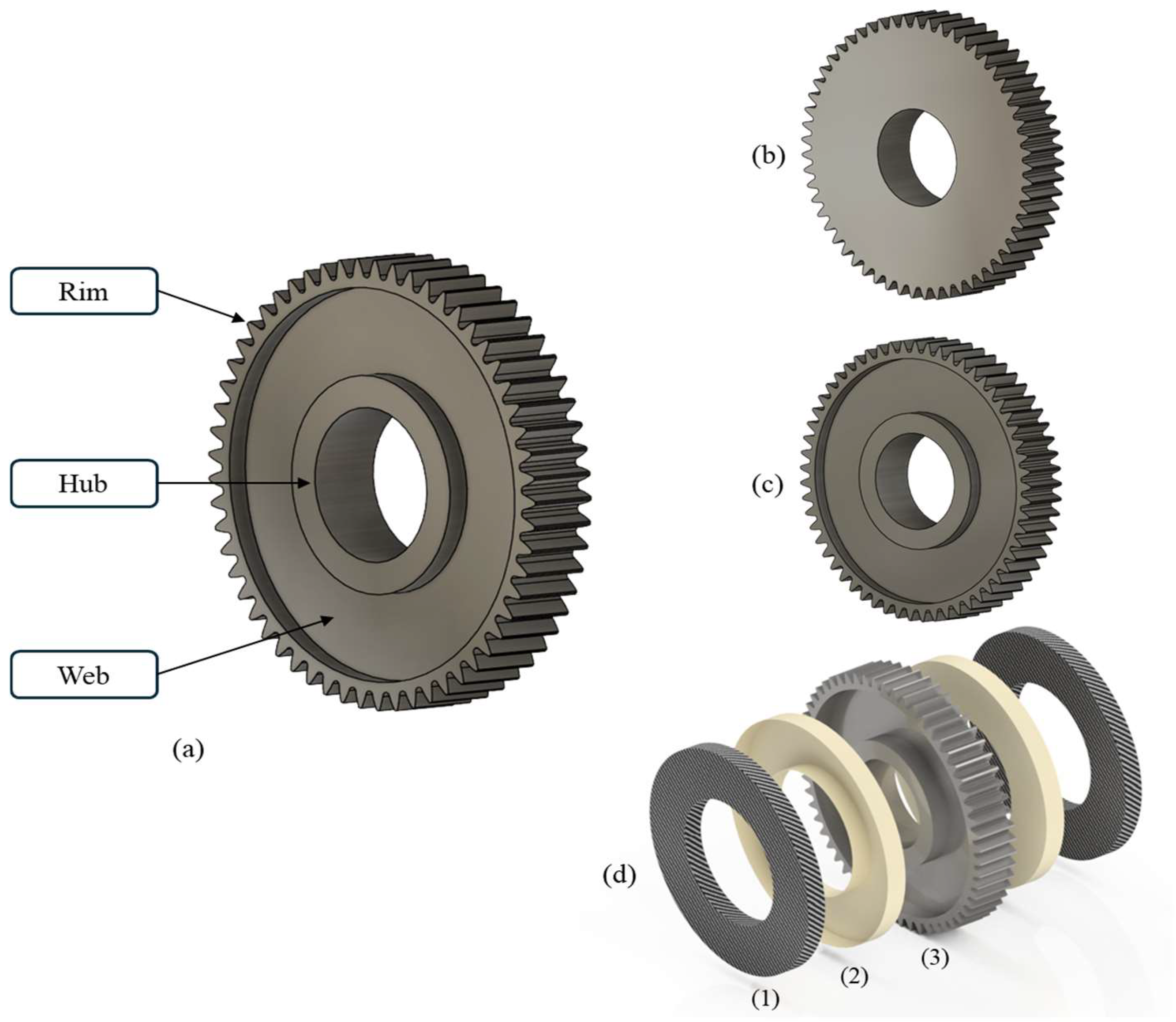
  • Mass reduction is one of the key drivers of performance enhancement in automotive as well as aerospace sectors to satisfy the increasingly strict regulations on combustion engine emission and fuel efficiency [6,7,44]. Current design solutions rely either on material removal from the gear blank [11,45] or on the combination of lightweight materials with high-performance steel [22] to decrease the gear mass. In both cases, the optimal design choice must prevent the deterioration of N&V performance [12], while preserving the structural integrity of the geared transmission.
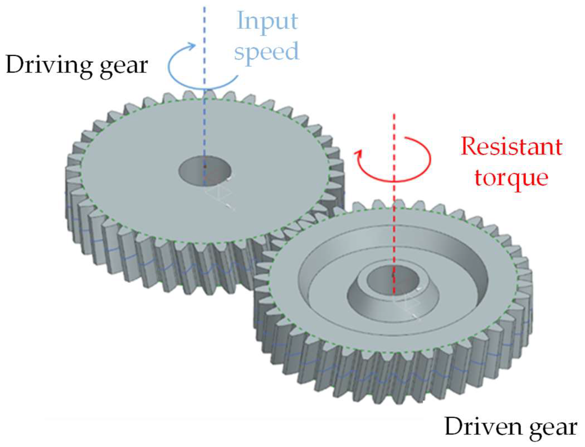
  • Despite gears being designed to be perfectly conjugate, the lightweighting process introduces additional gear body flexibilities that induce deviations from the ideal kinematic conditions, producing unwanted self-induced vibrations. These are often traced back to the static transmission error (STE) of two meshing gears [12]. It is defined as the degree of offset between conjugate and actual behavior of the meshing gears:
    T E = 1 τ Δ θ 2 Δ θ 1 ,
    where τ is the transmission ratio of the gear pair, while Δ θ1 and Δθ2 are the rotations of the driving and driven gears, respectively. Due to the variability of the TE over the meshing cycle and the harmonic nature of the rotating gears, internal induced vibrations are generated, which highly affects the N&V performance of a geared transmission. In order to assess the severity of parametric excitation at different load and velocity levels, the pick-to-pick (PtP) value of the TE has been demonstrated in [46] to be a valuable and synthetic metric.
In this work, in order to access the overall EoL performances of different design choices, the PtP STE metric of the innovative hybrid lightweight design described in the previous section is considered as a target to define a mono-material but lightweight design starting from a full gear body. This was achieved by varying the web thickness parameters of the lightweight gear in a discrete manner until the target was approximatively matched. Once the design of experiments was well defined, the PtP STE performances were virtually evaluated by means of an advanced MultiBody (MB) simulation platform, Simcenter Motion [47], where both varying contact stiffness and gear body flexibility were accounted for, as described in [48]. Figure 2 shows the MB model of a generic gear pair where a reference motion of 10 rpm is given in input to the full gear design and transmitted to the parametric lightweight gear on which a constant resistant torque of 100 Nm is applied [23]. A constant speed of 10 rpm was chosen with the aim of neglecting the dynamic effects of the gear, achieving quasi-static conditions [23], while the operationally relevant torque level of 100 Nm was selected among the experimentally validated torque sets presented in [23].
Finally, Table 3 summarizes the PtP STE metric for the evaluated gear designs. Moreover, it is highlighted in red that the lightweight gear design with a web thickness τ of 10 mm is the closest to the reference hybrid gear with an overall PtP STE difference of 0.014 µm. For completeness, the mass of the evaluated designs is also reported in Table 3 and will be considered in the next section for performing the environmental analysis.
The designed variable τ, whose variation ensures the desired PtP STE, allows us to compare the analyzed gears. The τ quantification, assuming a Static Transmission Error (STE) calculated by simulation, results in calculating the volume and, consequently, the mass (Mgear), for each analyzed gear, as detailed in Table 3.

2.1.2. Goal and Scope Definition

The LCE quantification allows assessing the environmental impacts of a product by using its life cycle. If the production process is considered, environmental impacts are assessed from the raw material processing. This phase is also called “Cradle”, which is part of the term “Cradle-to-Grave”. The term “grave” is derived from the last piece of material processing, when materials are recycled, disposed of, or lost.
The comparison of different masses and/or joining strategies of different materials can help decision-makers to reduce environmental impact, and the LCE quantification is a valuable tool that can be used to compare different products or different design alternatives with the same function and to highlight the useful phases in the product life cycle. The present LCE work describes a comparative environmental assessment of three different gear configurations with two different EoL scenarios, in order to select the proper configuration able to reduce the environmental impact during its entire life cycle. The analysis involves three different system products made with different materials as described in Figure 1. The functional unit (f.u.) is represented by the gears that were sized to have the same PtP STE with a different web thickness (τ), as described in the previous Section 2.1.1. The main goal of the work is to evaluate the best scenario to reduce the overall environmental impact during the entire life cycle of the gear, from a CED point of view.
This CED study is conducted by applying a cradle-to-grave approach, which includes all the unit processes involved in the production of the gear, from raw material extraction to product manufacturing and from use phase to different EoL scenarios. The work was performed according to the system boundaries as reported in Figure 3. Furthermore, the transport phase between the process units is excluded from the analysis, as it is assumed to be the same between process units and between the analyzed scenarios. The electricity production used in industrial processes is obtained from the combustion of natural resources, as shown in [42]. Considering the electric energy demand of the process, it was converted into primary energy source consumption by taking into account an average efficiency of 36% in order to consider the energy generation and transmission losses [49]. In order to assess the cumulative energy demand according to the Country’s energy mix, the factor 7.85 MJoe/kWh was used to convert the electricity of the manufacturing process into energy consumption [49]. For the performed analysis, the energy consumption refers to the European average energy mix.
Looking at the EoL phase of the investigated gears, the benchmark EoL scenario is the so-called conventional open loop scenario, allowing a CED assessment of a component that is processed by combustion and where the metal and composite scraps produced during the manufacturing processes are disposed of by landfill and incinerator, respectively. Indeed, considering this open loop process, the gear body is remelted to obtain the raw material. The second scenario analyzed in the study, the so-called closed loop, involves the recycling of the entire component with a remelting of the gear body and the metal scraps. In addition, in this case, the composite gear part is recycled by a pyrolysis process (thermal recycling). Specifically, the carbon fibers (CFs) are fully recovered by the pyrolysis process, while the epoxy matrix is burned [50]. Pyrolysis was chosen because several studies claim that if the decomposition process is carried out at a temperature range from 350 °C to 700 °C, this recycling process is the most efficient and reliable in terms of energy and material recovery [51,52,53,54]. Lastly, a cleaning step is required during the CF recycling. The cleaning phase is necessary to purify the reinforcement (CF) to make it ready for a new life cycle. The two different EoL scenarios, i.e., the conventional open loop scenario and closed loop scenario, are summarized in Figure 4. These EoL routes are considered as the “more usual” and the “more environmentally friendly” scenario, respectively.

2.1.3. Life Cycle Inventory (LCI)

The LCI data were generated by using different approaches. Data from scientific literature and technical reports were used. In detail, according to previous work [42], a great variability of data was reported. For this reason, in order to reduce the variance, an average value was used when a variability in data was encountered.
To evaluate the environmental impact of both metal and CFRP gear body, the material energies are considered. In detail, the energy aliquots linked to mineral extraction and to casting billet were considered for the alloy steel. The embodied energies of the reinforcements (CFs) and of the polymeric matrices, increased by the energy needed to perform sub-processes to combine fibers in yarns and to process these yarns to achieve the CFs prepregs, were taken into account for the CFRPs. These energy rates of the materials are represented by Hm, as detailed in Table 4.
At the end of the material energy quantification, a metallic billet and a pre-impregnated CFRP blank (prepregs) were analyzed. To consider the environmental impact of the manufacturing processes, the process energy rates were specified for each analyzed gear. Specifically, the starting cylindrical billet and prepregs are characterized by a volume of 5.03 × 105 mm3 and 3.83 × 105 mm3, respectively. The turning process, comprising the other sub-operation, i.e., roughing, finishing, drilling, and trimming, was considered to obtain the hub and the web section. The full and lightweight gears were manufactured by turning the manufacturing process regarding the web and hub sections, and by the hobbing process regarding the rim section. The process times for the turning phases of the initial billet were calculated numerically by using FeatureCam Ultimate software [55]. Specifically, the aim of the simulation was to optimize the process time by reducing the number of tool changes. Feed rates of 0.381 mm/rev and 0.152 mm/rev were set for the roughing and finishing phases, respectively. The tool insert is an SW rhombus 80 type with clockwise rotation. As a result, the simulated process times were estimated as 0.045 h, 0.503 h, and 0.533 h, for full, lightweight and hybrid gears, respectively. A standard CNC turning machine was used, and the estimated value of energy consumption was 7 kW, as reported in [40,56]. On the other hand, considering the rim section, the hobbing process was selected as being the most efficient and precise process. To determine the process parameters, a mathematical calculation was performed according to Wang et al. [57], allowing the hobbing process time to be calculated. In detail, the hobbing process time to obtain the selected gears was estimated as 1.72 h. The energy consumption value was estimated by a scientific technical report [58]. Concerning the lightweight gear, the web thickness, and consequently the turning process time, was defined by the numerical simulations, as described in the previous Section 2.1.1.
Furthermore, during the analysis, the impact of consumables was considered. The quantity of cutting fluid used during a standard machining process and the embodied energy of the cutting fluid were estimated from the literature. Specifically, according to [58], in a standard manufacturing process, the cutting fluid accounted for 2.24 mL/s, and according to [59], the environmental impact, from an energy point of view, accounted for 380.00 MJ/kg.
On the other hand, the hybrid gear (Figure 1d) was manufactured by following a multi-step process approach, as detailed in [23]. Rim and hub, linked by a 2 mm thick metal layer, were manufactured by using the same material and manufacturing process of the full and lightweight gears. In the web, the 2 mm thick layer was left to ensure axiality between the rim part and the hub, as demonstrated by Rezayat et al. [23]. Simultaneously, the axial direction gap was left to allow the housing of a 10.50 mm thick layer of composite laminate material on each side of the web section of the gear. In detail, overlapping pre-impregnated layers were considered, characterized by homogeneous in-plane properties and cured in an autoclave process to consolidate the different plies.
Furthermore, an abrasive water jet (AWJ) process is used to size the composite blank to the correct web section [60]. In addition, an adhesive layer is used for joining the metal and laminate parts. The amount of energy related to the used adhesive layer was taken from [49].
The overall energy portions considered during the gear manufacturing processes, grouped in Hp, are detailed in Table 5.
In order to evaluate the use phase for each analyzed gear, it was taken considered that each gear was mounted on an economy diesel car, which covers 250,000 km over its life, with a vehicle weight of 1400 kg [61]. The fuel consumption is 0.30 L for each km and for each travelled kg and its density was 0.85 kg/L [33,62]. According to [49], the energy intensity of diesel accounted for 44.00 MJ/kg. The energy consumption used in the whole use phase for each gear is represented by Hu and is estimated to be 746.77 MJ, 471.79 MJ, 426.51 MJ for full, lightweight and hybrid, respectively.
Finally, different EoL scenarios for the gear were assumed, strictly linked to the employed materials. Considering the metallic material, i.e., steel, the mass fraction of steel that could be recycled was recovered by a casting process. On the other hand, the steel scrap was disposed of in landfill. The energy for both of the above processes was obtained from [33,49] and accounted for 4.15 MJ/kg and 3.68 kWh/kg, respectively.
Considering the prepregs, the CFRP material was recycled by pyrolysis according to the recycling route first proposed by Pimenta et al. [50,63]. After the pyrolysis process, a cleaning step is required to obtain the recycled CFs. In detail, the energy required by the pyrolysis and cleaning process of the prepreg CFRP was extracted by [42] and accounted for 43.50 MJ/kg and 8.73 MJ/kg, respectively.

2.1.4. Life Cycle Energy Demand Assessment

The methodology proposed in [64], by Suzuki and Takahash, was applied to quantify the CED to perform a comparative analysis of the environmental impact in the case study described in the previous section. The life cycle energy demand assessment was performed using Equations (2)–(7).
The CED quantification of the target component assesses the environmental impact during its life cycle. The method considers the energy of the raw component production ( H m ) based on the weight of the gear strictly linked to the initial steel billet and, if it is present, to the employed composite prepregs, as summarized in Equation (2). Specifically, a H m portion of the component is calculated as the mass fraction of the used steel ( m f s ) and, if it is present, of the composite prepregs, made by carbon fibers ( m f C F s ) and polymeric resins ( m f E p o x y ) multiplied, respectively, by the embodied energy of the steel ( H m s ), of the fibers ( H m C F s ) and of the epoxy resins ( H m E p o x y ). The mass of the prepreg ( m f p r e p r e g ) employed in the gear body is the sum of m f C F s and m f E p o x y . H m also considers the contributions of the casting process required to achieve the initial metallic billet ( H c a s ) and all the specific sub-processes required to combine fiber and polymeric matrix to obtain the prepregs ( H p r e p r e g ) [25]. The energy of the gear manufacturing is taken into account by H p in Equation (3). This energy aliquot ( H p ) is calculated taking into account the manufacturing phases to process the metallic billet, achieving the final shape of the gear, i.e., turning ( H p t ) and hobbing processes ( H p h ), and, if present, the all-manufacturing phases to work on the prepregs to obtain the laminate utilized in the hybrid gear, i.e., autoclave molding ( H p a ) and cutting process ( H p c ). Subsequently, considering the hybrid gear, the joining phase ( H p a d h ) to assemble the metal and the laminate parts by an adhesive layer was considered. The energy related to the use phase ( H U ) was calculated for each analyzed gear, multiplying the mass fraction of consumed fuel ( m f f ) by the energy intensity of fuel ( H u _ s p e c i f i c ), as described in Equation (4). The overall energy for each target component is summed up by H g e a r in Equation (5).
H m = m f s · ( H m s + H c a s ) + ( m f C F s · H m C F s ) + ( m f E p o x y · H m E p o x y )
H P = H p t + H p h + H p a + H p c + H p a d h
H U = m f f · H u _ s p e c i f i c
H g e a r = H m + H P + H U  
Equation (5) can be used to quantify the CED of each target component without considering the EoL scenario and the scrap material produced during the gear manufacturing.
Concerning the EoL, the substitution method was considered. Specifically, the EoL contribution ( H E o L ) and the scrap material contribution ( H S c r a p ) to the cumulative energy of the gear ( H n e t ) can be evaluated by considering two different approaches, named “more usual” and “more environmentally friendly” depending on the implemented recycling scenario. If the more usual approach is taken into account, just the metallic part of the gear is recycled ( m f s G e a r ) at its EoL, while the epoxy resin of the CFRP is burned, recovering the heat ( H i n c ), and the wasted material in manufacturing, for both steel ( m f s m f s G e a r ) and CFRP ( s c r a p P r e p r e g ), are sent to the landfill ( H l a n d ). For this approach, H E o L and H S c r a p are calculated by Equation (6). If the more environmentally friendly approach is executed, H E o L and H S c r a p are quantified considering that the whole gear is properly recycled. In detail, pyrolysis, a thermal strategy [48], is employed to recycle the CFRP laminate ( H p y r o ). Furthermore, the wasted material is properly recovered by melting the metallic chips and burning the sheet scrap derived from the overlapping composite plies ( s c r a p P r e p r e g ) (Equation (7)). Equations (6) and (7) are made explicit below:
H U s u a l = R s · m f s G e a r · H m s H c a s + 1 R s · m f s G e a r · H l a n d m f P r e p r e g · H i n c + m f s m f s G e a r · H l a n d + s c r a p P r e p r e g · H l a n d
H E n v i r . = R s · m f s · H m s H c a s m f C F s · H m C F s H p y r o R s · m f s m f s G e a r · ( H m s H c a s ) ( s c r a p P r e p r e g · H i n c ) + 1 R s · m f s · H l a n d
where R s is the fraction of the steel that can be recovered by remelting it ( R s = 90 % ) [65].

3. Discussion of Results

The CED values for the three different gears, listed as full, lightweight and hybrid gears for the two different recycling approaches (i.e., the “more usual” and the “more environmentally friendly”), are reported in Figure 5. The CED results shown in Figure 5a were calculated for the entire life cycle of the analyzed gears for the “more usual” approach. Specifically, this EoL configuration was evaluated to provide an upper threshold value. In detail, the metallic gear body was recycled by remelting the part, the epoxy resin of the CFRP plies employed in the hybrid gear were burned to recover the heat, whereas all the other involved materials, i.e., the oxidized metallic part due to the casting process, the chip derived by the machining process and the scrap of composite laminate owing to the specific size of the gear web, were disposed of in a landfill. In this scenario, the process impacts related to metallic chips and to the overall composite laminate (scrap and web section of the hybrid gear) are accounted for in the ( H p ) for each analyzed gear. The energy of the raw component production ( H m ) has an impact of 142.65 MJ ( H m s + H c a s ) for the gears made of just steel, both for the full and the lightweight gear. On the other hand, for the hybrid gear, ( H m ) increases by about 175% owing to the CFRP production ( H p r e p r e g = 245.47), resulting in a cumulative impact of 388.12 MJ. Looking at the gear manufacturing ( H p ) , an opposite trend can be observed. Indeed, in this phase, the full gear is characterized by a reduced impact of 96.98 MJ, with a short machining phase ( H p t = 2.47 ,   H p h = 94.51 ) being necessary to achieve the final gear shape. In addition, a value of 35.68 MJ ( H l a n d ) from the landfilling of metal scrap generated during the manufacturing process was taken into account. Specifically, the ( H p ) value increases by 40.98% and 120.37% for lightweight and hybrid gear, respectively. For the lightweight configuration, the machining phase increases to dig the web ( H p t = 27.64 ) and consequently for the increase in metallic scrap ( H l a n d = 64.89 ). The ( H p ) increment for the hybrid variant takes into account the manufacturing of the prepregs ( H p a = 53.11 ) , the impact related to landfilling of metallic and composite waste ( H l a n d = 89.92 ) , the recovered heat due to the incineration of the CFRP laminate derived from gear web section ( H i n c = 11.16 ) and the impact of the adhesive bonding ( H p a d h = 9.50 ) and cutting phase ( H p c = 27.17 ) .
The use phase ( H u ) , being related to the weight of the components that consume fuel for their movement, sees the heavier full gear, with the more significant impact of 746.78 MJ. This CED aliquot is 75.08% and 58.29% higher than the lightweight (471.79) and hybrid gear (426.52), respectively.
The EoL phase of the gear was considered, applying the conventional open loop scenario described in Equation (5). Specifically, the considered aliquots for the EoL phase are 60.13 MJ, 37.74 MJ, and 23.95 MJ for the full, lightweight, and hybrid gear, respectively. Finally, considering the whole life cycle with a cradle-to-grave approach ( H n e t ) , the hybrid gear was shown to be comparable to the full gear, with an increase of 12.58% in CED. On the other hand, in this scenario, the lightweight gear allows an advantage, in terms of CED recovery, of 41.81% over the hybrid gear.
On the other hand, the results of the “more environmentally friendly” approach are shown in Figure 5b, which provides lower threshold values. In detail, the closed loop scenario was considered for the EoL of the gear and of the materials wasted during the manufacturing phases. In this approach, for the full gear, H m takes into account the metallic chip recovered by a casting process and quantified by ( H c h i p c a s = 30.93 ) . H c h i p c a s is −56.25 and −71.84 for lightweight and hybrid gear, respectively, considering the different quantity of removed material from the initial casting billet.
Concerning H p , the H l a n d related to the metallic chip is not considered because it is properly recycled. Actually, just the oxidized chip portion is landfilled, accounting for 3.57, 6.49 and 8.29 in the full, lightweight and hybrid gear, respectively. Furthermore, for the hybrid gear, the thermal energy of prepreg scraps is recovered ( H i n c . = 7.80 ) . Nothing changes for the use-phase as compared to the first approach.
Finally, considering EoL, the hybrid gear, which includes the metallic gear body recycled by a remelting process and composite prepreg web section recycled by a pyrolysis process, enables a CED recovery of 259.01 MJ. The high recovered energy rate is mainly due to the high impact of the production of virgin CFs.
The overall CED assessment ( H n e t ) for the “more environmentally friendly” approach results in the values of 898.92 MJ, 649.10 MJ, 697.87 MJ considering the full, lightweight and hybrid gear, respectively. In this scenario, the lightweight and hybrid solutions are shown to be comparable, with a CED difference around 7.50%. On the other hand, the hybrid gear reaches a CED saving of 28.82% if compared to the full gear.

4. Conclusions

The LCE study proposed herein, from a CED point of view, provides useful elements for practitioners in environmental impact study, considering the entire gear life cycle. In detail, based on the performed analysis, different gears, but with similar mechanical performance, were compared considering diverse EoL strategies based on an open and a closed loop scenario. Synthesizing a full-steel gear was compared to a lightweight gear, characterized by a reduced web thickness, and a hybrid gear, where the web is made of a polymeric matrix composite reinforced by continuous CFs. The possible EoL scenarios were studied, from a theoretical point of view, collecting the required energy quantification of each phase in the product life from its cradle to its grave.
Assuming that the best environmental choice can be more or less convenient depending on the scenarios analyzed, the hybrid gear proved its competitiveness with respect to the full gear not just in terms of performance enabled by the reduced weight, which is guaranteed.
The performed analysis highlighted the following key findings:
  • The high environmental impact from an energy perspective, primarily attributable to the LCE associated with the CFRP laminate, prevents the hybrid gear from being considered environmentally friendly without the implementation of an appropriate EoL strategy. This is particularly evident when compared to the lightweight solution.
  • The CED required for manufacturing hybrid gears could be significantly reduced with the adoption of effective recycling strategies. This would enhance the competitiveness of the hybrid solution, not only during the use phase, where its reduced weight is advantageous, but also in a comprehensive cradle-to-grave analysis.
As a conclusion of the study, examining the overall CED rating for the “more environmentally friendly” approach, and therefore for the correct recycling strategies, yields values of 898.92 MJ, 649.10 MJ and 697.87 MJ for full, light and hybrid gears, respectively. In this scenario, the lightweight and hybrid solutions demonstrate comparable energy demands, with the hybrid gear exhibiting a slight advantage, reflecting a CED difference of approximately 7.50%.
However, the hybrid gear offers a significant benefit when compared to the full gear, achieving a notable CED reduction of 28.82%. This substantial saving underscores the potential of hybrid gears as a more sustainable alternative, provided that effective recycling and manufacturing strategies are implemented.
The findings of the present work highlight the balance between material innovation and environmental performance, suggesting that hybrid gears, while slightly less efficient than lightweight gears from a CED perspective, still present a compelling case for reducing environmental impact when compared to traditional full-steel gears. This makes them an attractive option for applications where weight reduction and sustainability are critical considerations.
As far as future developments are concerned, loss in performance for the long fibers due to the recycling phase or limitations due to the system boundaries, due to the country’s energy mix, will be considered. Furthermore, the LCE study will be extended to a full analysis considering additional midpoint indicators, such as global warming, mineral resource depletion, terrestrial acidification, as well as endpoint indicators, such as human health, ecosystem quality and resource availability. The full analysis is required to investigate the gear impacts, looking at different environmental indicators and providing different point of views necessary to achieve a more general quantification of the contribution that properly designed mechanisms prove to have on ecosystem protection.

Author Contributions

Conceptualization, F.G. and D.M.; methodology, F.B. and R.A.; software, F.B. and R.A.; validation, F.G. and D.M.; formal analysis, F.B.; investigation, F.B. and R.A.; resources, F.G.; data curation, F.B. and R.A.; writing—original draft preparation, F.B., F.G., R.A. and D.M.; writing—review and editing, F.B., F.G. and R.A.; visualization, F.B.; supervision, F.G. and D.M. All authors have read and agreed to the published version of the manuscript.

Funding

This research received no external funding.

Data Availability Statement

Data and optimization code will be made available upon request to interested researchers.

Conflicts of Interest

The authors declare no conflicts of interest.

References

  1. Nie, Y.; Li, F.; Wang, L.; Li, J.; Li, Y.; Sun, M.; Wang, M.; Li, G. A Novel Vibration Model for Explanation of the Frequency Features in Multistage Wind Turbine Gearboxes Considering the Effects of Inter-stage Meshing Frequency Modulation. Int. J. Precis. Eng. Manuf. Technol. 2022, 10, 151–166. [Google Scholar] [CrossRef]
  2. Kawasaki, K.; Tsuji, I. Manufacturing Method for Large Cylindrical Worm Gear Set of ISO Type I on Universal CNC Machine Tools. J. Manuf. Mater. Process. 2023, 7, 53. [Google Scholar] [CrossRef]
  3. Perdomo, I.L.F.; Quiza, R.; Haeseldonckx, D.; Rivas, M. Sustainability-Focused Multi-objective Optimization of a Turning process. Int. J. Precis. Eng. Manuf. Technol. 2019, 7, 1009–1018. [Google Scholar] [CrossRef]
  4. Zhu, M.; Wei, C.; Guo, W.; Zhang, Z.; Ouyang, J.; Mativenga, P.; Li, L. Significant Reduction in Energy Consumption and Carbon Emission While Improving Productivity in Laser Drilling of CFRP Sheets with a Novel Stepped Process Parameter Parallel Ring Method. J. Manuf. Mater. Process. 2022, 6, 7. [Google Scholar] [CrossRef]
  5. Dér, A.; Kaluza, A.; Reimer, L.; Herrmann, C.; Thiede, S. Integration of Energy Oriented Manufacturing Simulation into the Life Cycle Evaluation of Lightweight Body Parts. Int. J. Precis. Eng. Manuf. Technol. 2022, 9, 899–918. [Google Scholar] [CrossRef]
  6. NASA. NASA’s Revolutionary Hybrid Gear Lightens Your Load. 2016. Available online: https://www.newequipment.com/research-and-development/article/22058083/nasas-revolutionary-hybrid-gear-lightens-your-load (accessed on 3 September 2024).
  7. Dobrzański, L.; Tański, T.; Čížek, L.; Brytan, Z. Structure and properties of magnesium cast alloys. J. Mech. Work. Technol. 2007, 192–193, 567–574. [Google Scholar] [CrossRef]
  8. Pavlović, A.; Sintoni, D.; Minak, G.; Fragassa, C. On the modal behaviour of ultralight composite sandwich automotive panels. Compos. Struct. 2020, 248, 112523. [Google Scholar] [CrossRef]
  9. Suski, C.A.; Filho, J.F.S.; Cortez, A.; Gonçalves, F.E.; Ferreira, R.R. The environmental impact of lightweight body in white structures in vehicle manufacturing. J. Clean. Prod. 2024, 449, 141833. [Google Scholar] [CrossRef]
  10. Ullah, A.S. Machining Forces Due to Turning of Bimetallic Objects Made of Aluminum, Titanium, Cast Iron, and Mild/Stainless Steel. J. Manuf. Mater. Process. 2018, 2, 68. [Google Scholar] [CrossRef]
  11. Silva, F.J.G.; Martinho, R.P.; Magalhães, L.L.; Fernandes, F.; Sales-Contini, R.C.M.; Durão, L.M.; Casais, R.C.B.; Sousa, V.F.C. A Comparative Study of Different Milling Strategies on Productivity, Tool Wear, Surface Roughness, and Vibration. J. Manuf. Mater. Process. 2024, 8, 115. [Google Scholar] [CrossRef]
  12. Shweiki, S.; Palermo, A.; Mundo, D. A Study on the Dynamic Behaviour of Lightweight Gears. Shock. Vib. 2017, 2017, 7982170. [Google Scholar] [CrossRef]
  13. Handschuh, R.F.; Roberts, G.D.; Sinnamon, R.R.; Stringer, D.B.; Dykas, B.D.; Kohlman, L.W. Hybrid Gear Preliminary Results-Application of Composites to Dynamic Mechanical Components. 2012. Available online: https://ntrs.nasa.gov/citations/20120005332 (accessed on 10 November 2024).
  14. Qi, L.; Li, C.; Yu, X.; Min, W.; Shi, H.; Tao, L.; Wang, H.; Yu, M.; Ni, L.; Sun, Z. Effect of reinforced fibers on the vibration characteristics of fibers reinforced composite shaft tubes with metal flanges. Compos. Struct. 2021, 275, 114460. [Google Scholar] [CrossRef]
  15. Sauer, K.; Dix, M.; Putz, M. Process Forces Analysis and a New Feed Control Strategy for Drilling of Unidirectional Carbon Fiber Reinforced Plastics (UD-CFRP). J. Manuf. Mater. Process. 2018, 2, 46. [Google Scholar] [CrossRef]
  16. Laberge, K.E.; Thorp, S. Performance Investigation of a Full-Scale Hybrid Composite Bull Gear. In Proceedings of the Vertical Flight Society 72nd Annual Forum & Technology Display, West Palm Beach, FL, USA, 16–19 May 2015. [Google Scholar]
  17. Laberge, K.E.; Johnston, J.P.; Handschuh, R.F. Evaluation of a Variable Thickness Hybrid Composite Bull Gear. In Proceedings of the Vertical Flight Society 74th Annual Forum & Technology Display, Phoenix, AZ, USA, 14–17 May 2018. [Google Scholar]
  18. Catera, P.G.; Mundo, D.; Treviso, A.; Gagliardi, F.; Visrolia, A. On the Design and Simulation of Hybrid Metal-Composite Gears. Appl. Compos. Mater. 2018, 26, 817–833. [Google Scholar] [CrossRef]
  19. Isaac, C.W.; Ezekwem, C. A review of the crashworthiness performance of energy absorbing composite structure within the context of materials, manufacturing and maintenance for sustainability. Compos. Struct. 2020, 257, 113081. [Google Scholar] [CrossRef]
  20. Zheng, C.; Duan, F.; Liang, S. Manufacturing and mechanical performance of novel epoxy resin matrix carbon fiber reinforced damping composites. Compos. Struct. 2020, 256, 113099. [Google Scholar] [CrossRef]
  21. Catera, P.G.; Gagliardi, F.; Mundo, D.; De Napoli, L.; Matveeva, A.; Farkas, L. Multi-scale modeling of triaxial braided composites for FE-based modal analysis of hybrid metal-composite gears. Compos. Struct. 2017, 182, 116–123. [Google Scholar] [CrossRef]
  22. Catera, P.G.; Mundo, D.; Gagliardi, F.; Treviso, A. A comparative analysis of adhesive bonding and interference fitting as joining technologies for hybrid metal-composite gear manufacturing. Int. J. Interact. Des. Manuf. 2020, 14, 535–550. [Google Scholar] [CrossRef]
  23. Rezayat, A.; Catera, P.G.; Capalbo, C.; Cosco, F.; Mundo, D. Numerical and experimental analysis of the transmission error in hybrid metal-composite gears. Compos. Struct. 2022, 298, 116012. [Google Scholar] [CrossRef]
  24. Yılmaz, T.G.; Doğan, O.; Karpat, F. A numerical investigation on the hybrid spur gears: Stress and dynamic analysis. Proc. Inst. Mech. Eng. Part C J. Mech. Eng. Sci. 2020, 236, 354–369. [Google Scholar] [CrossRef]
  25. Gauntt, S.M.; Campbell, R.L. Characterization of a Hybrid (Steel-Composite) Gear with Various Composite Materials and Layups. In Proceedings of the AIAA Scitech 2019 Forum, Reston, Virginia: American Institute of Aeronautics and Astronautics, San Diego, CA, USA, 7–11 January 2018. [Google Scholar] [CrossRef]
  26. Jiang, S.; Li, W.; Xin, G.; Sheng, L.; Wang, Y. Study on dynamic reliability of permanent magnet gear transmission system with wear and failure correlation. Eng. Fail. Anal. 2021, 131, 105802. [Google Scholar] [CrossRef]
  27. Skulić, A.; Bukvić, M.; Gajević, S.; Miladinović, S.; Stojanović, B. The influence of worm gear material and lubricant on the efficiency and coefficient of friction. Tribol. Mater. 2024, 3, 15–23. [Google Scholar] [CrossRef]
  28. Czakó, A.; Řehák, K.; Prokop, A.; Rekem, J.; Láštic, D.; Trochta, M. Static transmission error measurement of various gear-shaft systems by finite element analysis. J. Meas. Eng. 2023, 12, 183–198. [Google Scholar] [CrossRef]
  29. European Council. Industrial Emissions. 2024. Available online: https://www.consilium.europa.eu/en/press/press-releases/2024/04/12/industrial-emissions-council-signs-off-on-updated-rules-to-better-protect-the-environment/ (accessed on 9 December 2024).
  30. International Energy Agency. Energy System of EUROPE. 2023. Available online: https://www.iea.org/energy-system (accessed on 9 December 2024).
  31. Campos-Romero, H.; Rodil-Marzábal, Ó.; Gómez Pérez, A.L. Environmental asymmetries in global value chains: The case of the European automotive sector. J. Clean. Prod. 2024, 449, 141606. [Google Scholar] [CrossRef]
  32. International Energy Agency. Industry Energy System. 2023. Available online: https://www.iea.org/energy-system/industry (accessed on 9 December 2024).
  33. Gagliardi, F.; La Rosa, A.D.; Filice, L.; Ambrogio, G. Environmental impact of material selection in a car body component—The side door intrusion beam. J. Clean. Prod. 2021, 318, 128528. [Google Scholar] [CrossRef]
  34. Kim, H.C.; Wallington, T.J. Life Cycle Assessment of Vehicle Lightweighting: A Physics-Based Model to Estimate Use-Phase Fuel Consumption of Electrified Vehicles. Environ. Sci. Technol. 2016, 50, 11226–11233. [Google Scholar] [CrossRef]
  35. Luk, J.M.; Kim, H.C.; De Kleine, R.D.; Wallington, T.J.; MacLean, H.L. Greenhouse gas emission benefits of vehicle lightweighting: Monte Carlo probabalistic analysis of the multi material lightweight vehicle glider. Transp. Res. Part D Transp. Environ. 2018, 62, 1–10. [Google Scholar] [CrossRef]
  36. Choi, J.Y.; Jeon, J.H.; Lyu, J.H.; Park, J.; Kim, G.Y.; Chey, S.Y.; Quan, Y.-J.; Bhandari, B.; Prusty, B.G.; Ahn, S.-H. Current Applications and Development of Composite Manufacturing Processes for Future Mobility. Int. J. Precis. Eng. Manuf. Technol. 2022, 10, 269–291. [Google Scholar] [CrossRef]
  37. Kirchain, R.E., Jr.; Gregory, J.R.; Olivetti, E.A. Environmental life-cycle assessment. Nat. Mater. 2017, 16, 693–697. [Google Scholar] [CrossRef]
  38. Rödger, J.-M.; Beier, J.; Schönemann, M.; Schulze, C.; Thiede, S.; Bey, N.; Herrmann, C.; Hauschild, M.Z. Combining Life Cycle Assessment and Manufacturing System Simulation: Evaluating Dynamic Impacts from Renewable Energy Supply on Product-Specific Environmental Footprints. Int. J. Precis. Eng. Manuf. Technol. 2020, 8, 1007–1026. [Google Scholar] [CrossRef]
  39. Galve, J.E.; Elduque, D.; Pina, C.; Javierre, C. Life Cycle Assessment of a Plastic Part Injected with Recycled Polypropylene: A Comparison with Alternative Virgin Materials. Int. J. Precis. Eng. Manuf. Technol. 2021, 9, 919–932. [Google Scholar] [CrossRef]
  40. Borda, F.; La Rosa, A.D.; Filice, L.; Gagliardi, F. Environmental impact of process constrained topology optimization design on automotive component’ life. Int. J. Mater. Form. 2023, 16, 48. [Google Scholar] [CrossRef]
  41. Zhu, Y.; Kang, Z. A topology optimization framework for 3D phononic crystals via the method of successive iteration of analysis and design. Compos. Struct. 2023, 326, 117641. [Google Scholar] [CrossRef]
  42. Borda, F.; Ingarao, G.; Ambrogio, G.; Gagliardi, F. Cumulative energy demand analysis in the current manufacturing and end-of-life strategies for a polymeric composite at different fibre-matrix combinations. J. Clean. Prod. 2024, 69, 141775. [Google Scholar] [CrossRef]
  43. Bhong, M.; Khan, T.K.; Devade, K.; Krishna, B.V.; Sura, S.; Eftikhaar, H.; Thethi, H.P.; Gupta, N. Review of composite materials and applications. Mater. Today Proc. 2023, in press. [Google Scholar] [CrossRef]
  44. Ohrn, K.E. Aircraft Energy Use. In Encyclopedia of Energy Engineering and Technology, 2nd ed.; CRC Press: Boca Raton, FL, USA, 2014; pp. 32–38. [Google Scholar] [CrossRef]
  45. Benaïcha, Y.; Mélot, A.; Rigaud, E.; Beley, J.-D.; Thouverez, F.; Perret-Liaudet, J. A decomposition method for the fast computation of the transmission error of gears with holes. J. Sound Vib. 2022, 532, 116927. [Google Scholar] [CrossRef]
  46. Palermo, A.; Britte, L.; Janssens, K.; Mundo, D.; Desmet, W. The measurement of Gear Transmission Error as an NVH indicator: Theoretical discussion and industrial application via low-cost digital encoders to an all-electric vehicle gearbox. Mech. Syst. Signal Process. 2018, 110, 368–389. [Google Scholar] [CrossRef]
  47. Siemens PLM Software. Boosting Productivity in Gearbox Engineering; Siemens PLM Software: Plano, TX, USA, 2019; Available online: https://www.plm.automation.siemens.com/media/global/it/CE-37062-Siemens%20SW%20Boosting%20productivity%20in%20gearbox%20engineering%20wp_tcm56-71442.pdf (accessed on 4 January 2025).
  48. Cosco, F.; Adduci, R.; Muzzi, L.; Rezayat, A.; Mundo, D. Multiobjective Design Optimization of Lightweight Gears. Machines 2022, 10, 779. [Google Scholar] [CrossRef]
  49. Ashby, M.F. Materials and the Environment: Eco-Informed Material Choice; Elsevier: Amsterdam, The Netherlands, 2021. [Google Scholar]
  50. Pimenta, S.; Pinho, S.T. The effect of recycling on the mechanical response of carbon fibres and their composites. Compos. Struct. 2012, 94, 3669–3684. [Google Scholar] [CrossRef]
  51. Abdou, T.R.; Espinosa, D.C.R.; Tenório, J.A.S. Recovering of Carbon Fiber Present in an Industrial Polymeric Composite Waste Through Pyrolysis Method while Studying the Influence of Resin Impregnation Process: Prepreg. In REWAS 2016; Springer International Publishing: Berlin/Heidelberg, Germany, 2016; pp. 313–318. [Google Scholar] [CrossRef]
  52. Giorgini, L.; Benelli, T.; Mazzocchetti, L.; Leonardi, C.; Zattini, G.; Minak, G.; Dolcini, E.; Cavazzoni, M.; Montanari, I.; Tosi, C. Recovery of carbon fibers from cured and uncured carbon fiber reinforced composites wastes and their use as feedstock for a new composite production. Polym. Compos. 2015, 36, 1084–1095. [Google Scholar] [CrossRef]
  53. Meyer, L.; Schulte, K.; Grove-Nielsen, E. CFRP-Recycling Following a Pyrolysis Route: Process Optimization and Potentials. J. Compos. Mater. 2009, 43, 1121–1132. [Google Scholar] [CrossRef]
  54. Witik, R.A.; Teuscher, R.; Michaud, V.; Ludwig, C.; Månson, J.-A.E. Carbon fibre reinforced composite waste: An environmental assessment of recycling, energy recovery and landfilling. Compos. Part A Appl. Sci. Manuf. 2013, 49, 89–99. [Google Scholar] [CrossRef]
  55. Autodesk. FeatureCAM Ultimate 2024; Version 7.27; Autodesk Inc.: San Rafael, CA, USA, 2024; Available online: https://www.autodesk.com/products/featurecam/overview (accessed on 4 January 2025).
  56. Ingarao, G.; Priarone, P.C. A comparative assessment of energy demand and life cycle costs for additive- and subtractive-based manufacturing approaches. J. Manuf. Process. 2020, 56, 1219–1229. [Google Scholar] [CrossRef]
  57. Wang, J.; Dong, J. Prediction and optimization of hobbing parameters for minimizing energy consumption and gear geometric deviations. Adv. Mech. Eng. 2024, 16, 4. [Google Scholar] [CrossRef]
  58. Soares, L.A.P.; Firmino, A.S.; de Oliveira, J.A.; Silva, D.A.L.; Saavedra, Y.M.B.; Moris, V.A.d.S. Comparative LCA of automotive gear hobbing processes with flood lubrication and MQL. Int. J. Adv. Manuf. Technol. 2021, 119, 1071–1090. [Google Scholar] [CrossRef]
  59. Liu, Z.; Li, C.; Fang, X.; Guo, Y. Cumulative energy demand and environmental impact in sustainable machining of inconel superalloy. J. Clean. Prod. 2018, 181, 329–336. [Google Scholar] [CrossRef]
  60. Guglielmi, G.; Mitchell, B.; Song, C.; Kinsey, B.L.; Mo, W. Life Cycle Environmental and Economic Comparison of Water Droplet Machining and Traditional Abrasive Waterjet Cutting. Sustainability 2021, 13, 12275. [Google Scholar] [CrossRef]
  61. Candelaresi, D.; Valente, A.; Bargiacchi, E.; Spazzafumo, G. Life cycle assessment of hybrid passenger electric vehicle. In Hybrid Technologies for Power Generation; Elsevier: Amsterdam, The Netherlands, 2022; pp. 475–495. [Google Scholar] [CrossRef]
  62. Speight, J.G. Production, properties and environmental impact of hydrocarbon fuel conversion. In Advances in Clean Hydrocarbon Fuel Processing; Elsevier: Amsterdam, The Netherlands, 2011; pp. 54–82. [Google Scholar] [CrossRef]
  63. Pimenta, S.; Pinho, S.T. Recycling carbon fibre reinforced polymers for structural applications: Technology review and market outlook. Waste Manag. 2011, 31, 378–392. [Google Scholar] [CrossRef]
  64. Suzuki, T.; Takahash, J. Prediction of Energy Intensity of Carbon Fiber Reinforced Plastics for Mass-Produced Passenger CARS. In Proceedings of the Ninth Japan International SAMPE Symposium, Tokyo, Japan, 29 November 2005. [Google Scholar]
  65. EuRIC—European Recycling Industries’ Confederation. Metal Recycling Factsheet; EuRIC: Brussels, Belgium, 2020; Available online: https://circulareconomy.europa.eu/platform/sites/default/files/euric_metal_recycling_factsheet.pdf (accessed on 4 January 2025).
Figure 1. On the left side, (a) detail of each conventional gear section; on the right, the detail of the analyzed gears: (b) full, (c) lightweight and (d) detail of hybrid composite gear; (1) composite web, (2) adhesive layer, (3) metal gear body.
Jmmp 09 00014 g001
Figure 2. MB model of the considered lightweight gear transmission: the driving gear design is fixed and full, while the driven gear is parametric and lightweight.
Jmmp 09 00014 g002
Figure 3. System boundaries.
Jmmp 09 00014 g003
Figure 4. Details of the “more usual” and “more environmentally friendly” analyzed EoL scenarios.
Jmmp 09 00014 g004
Figure 5. Energy impacts of the different steps in the whole cradle-to-grave product’s life for (a) conventional open loop scenario and (b) closed loop scenario.
Jmmp 09 00014 g005
Table 1. Main dimensions of the analyzed gear [12].
ParameterValue
Teeth number59
Module2.5 mm
Pressure angle20°
Face width24 mm
Tip diameter154 mm
Root diameter142.75 mm
Theoretical pitch diameter147.50 mm
Base diameter138.60 mm
Table 2. Main properties of the composite material.
PropertyFiberMatrix
Material typeCarbon M40JEpoxy
Longitudinal Modulus [GPa]3772.7
Transverse Modulus [GPa]152.7
Shear Modulus [GPa]24.7 Long./5.0 Transverse1
Poisson’s ratio [-]0.410.35
Density [g/cm3]1.771.2
Table 3. Summary of the evaluated gear designs in terms of PtP STE and mass of the driven gear.
ComponentWeb Thickness τ [mm]PtP STE [µm]PtP STE Difference [µm]Mass [kg]
Hybrid gear-1.963reference1.539
Full gear231.706−0.2572.674
Lightweight gear151.8490.1142.148
12.51.9070.0561.954
101.9770.0141.761
7.52.0720.1091.567
52.1930.2301.373
Table 4. Embodied and manufacturing energy of investigated material for each analyzed gear.
NomenclatureMaterial EnergyEnergy Consumption [MJ/kg]References
H m Steel   embodied   energy   ( H m s ) 32.00[49]
Steel   casting   energy   ( H c a s ) 4.15[49]
CFs   embodied   energy   ( H m C F s ) 722.39[42]
Epoxy   embodied   energy ( H m E p o x y ) 117.50[49]
Prepreg   manufacturing   ( H p r e p r e g ) 132.63[42]
Table 5. Energy consumption during product manufacturing process for each analyzed gear.
NomenclatureManufacturing ProcessesEnergy ConsumptionUnitReferences
H p fulllightweighthybrid
Turning ( H p t ) 0.313.523.73kWh/pcCalculated
Hobbing ( H p h ) 12.0412.0412.04kWh/pcCalculated
Autoclave ( H p a ) --152.34MJ/kg[49]
Adhesive ( H p a d h ) --117.50MJ/kg[49]
AWJ   ( H p c ) --3.46kWh/pc[60]
Disclaimer/Publisher’s Note: The statements, opinions and data contained in all publications are solely those of the individual author(s) and contributor(s) and not of MDPI and/or the editor(s). MDPI and/or the editor(s) disclaim responsibility for any injury to people or property resulting from any ideas, methods, instructions or products referred to in the content.

