Article

Flexural Analysis of Additively Manufactured Continuous Fiber-Reinforced Honeycomb Sandwich Structures

by
Rafael Guerra Silva
1,
Esteban Gonzalez
2,
Andres Inostroza
2 and
Gustavo Morales Pavez
2,*
1
Industrial Technology and Packaging, California State Polytechnic University, San Luis Obispo, CA 93407, USA
2
School of Mechanical Engineering, Pontificia Universidad Católica de Valparaíso, Valparaíso 2340025, Chile
*
Author to whom correspondence should be addressed.
J. Manuf. Mater. Process. 2024, 8(5), 226; https://doi.org/10.3390/jmmp8050226
Submission received: 21 August 2024 / Revised: 25 September 2024 / Accepted: 6 October 2024 / Published: 10 October 2024

Abstract

:
This study explores the flexural behavior of continuous fiber-reinforced composite sandwich structures built entirely using material extrusion additive manufacturing. The continuous fiber additive manufacturing system used in this study works sequentially, thus enabling the addition of fiber reinforcement just in the face sheets, where it is most effective. Three-point bending tests were carried out on sandwich panel specimens built using thermoplastic reinforced with continuous glass fiber to quantify the effect of fiber reinforcement and infill density in the flexural properties and failure mode. Sandwich structures containing continuous fiber reinforcement had higher flexural strength and rigidity than unreinforced sandwiches. On the other hand, an increase in the lattice core density did not improve the flexural strength and rigidity. The elastic modulus of fiber-reinforced 3D-printed sandwich panels exceeded the predictions of the analytical models; the equivalent homogeneous model had the best performance, with a 15% relative error. However, analytical models could not correctly predict the failure mode: wrinkle failure occurs at 75% and 30% of the critical load in fiber-reinforced sandwiches with low- and high-density cores, respectively. Furthermore, no model is currently available to predict interlayer debonding between the matrix and the thermoplastic coating of fiber layers. Divergences between analytical models and experimental results could be attributed to the simplifications in the models that do not consider defects inherent to additive manufacturing, such as air gaps and poor interlaminar bonding.

1. Introduction

Material Extrusion Additive Manufacturing, also known as Fused Filament Fabrication (FFF) or Fused Deposition Modeling (FDM), is one of the most widespread additive manufacturing (AM) methods because of its affordability, simplicity, and flexibility. In FFF, the thermoplastic filament is extruded through a heated nozzle and deposited in the XY plane, forming a layer of solid material on the build plate. After printing one layer, the head moves along the Z-axis, positioning the nozzle to build the next layer. This layer-by-layer process enables the construction of elaborate shapes. Different thermoplastic materials such as polylactic acid (PLA), acrylonitrile butadiene-styrene (ABS), polypropylene (PP), and nylon can be used in this process, as well as thermoplastics reinforced with particles and fibers.
FFF can be used to produce architected cellular materials, in which solid and empty spaces are rearranged inside a structure to have specific material properties, such as a high stiffness-to-weight ratio or auxetic behavior. Honeycomb structures are the most widely known examples of these materials, but they also include lattice, cellular, and metamaterial structures [1]. A recent review by Cuan-Urquizo et al. [2] summarizes the vast array of geometries (or unit cell types) and mechanical properties that can be successfully produced using FFF.
Among the designed cellular materials, the use of honeycomb structures for lightweight sandwich structures in aerospace is well documented because of their exceptional strength-to-weight ratios. The honeycomb design comprises a series of hexagonal or similar-shaped cells formed into panels using aluminum or composite materials such as carbon fiber-reinforced polymers. Different authors have tested hexagonal honeycomb structures built via FFF using polymers, highlighting their flexural properties [3,4,5,6,7,8,9,10,11]. Cuan-Urquizo et al. [2] recently presented a survey of previous studies that have reported on polymer lattice structures manufactured by FFF tested under bending, reporting higher relative densities and hexagonal honeycomb structures as the best options for achieving higher stiffness in sandwich structures. In addition to those studies focusing on lattice structures, some authors have also evaluated sandwich structures built integrally via FFF [4,7,8,12,13] using different polymers such as PLA [4,6,13,14], ABS [9], ABS plus [15,16]; TPU [11], and PC [10].
Sandwich panels have also been fabricated from lattice cores built via FFF joined to facings 3D printed separately [5] or composite sheets constructed using other methods [14,16,17]. This includes lattice cores and sheets built integrally using FFF [3,5,6,11,15,18,19,20] and FFF lattice cores joined to faces using adhesives. In the latter, faces were either built separately via FFF [5] or from composite sheets produced by other methods [14,16]. This route enables the construction of cores with complex lattice structures (by FFF) and composite sheets from advanced materials that are not feasible using standard FFF printers. Composite sandwich structures with 3D-printed polymer cores have a satisfactory strength-to-weight ratio comparable to that of balsa core sandwich composites [17]. More recently, Fores-Garriga et al. [21] explored a wide array of 2D and 3D lattice cores built in polyetherimide, testing the effect of cell geometry and relative density. The authors reported that some polymer cellular cores can outperform PU250 foam and are comparable to Nomex and aluminum honeycombs, materials commonly used as cores in sandwich structures.
Reinforcement materials can be added before or during the FFF process to produce composite materials with better mechanical properties. Particles or short fiber reinforcement can be added to the filament, enabling the manufacturing of composite materials using standard FFF printers [22,23]. In pellet-based FFF printers, similar reinforcements can be mixed with the polymer feedstock, resulting in a composite mix fed to the extruder head [23,24,25]. The use of short fiber-reinforced composite materials, specifically PLA reinforced with short vegetal fibers such as hemp [5], wood [26], and flax [12]; to produce sandwich structures using FFF has also been explored. However, no direct comparison to non-reinforced materials was reported.
The production of continuous fiber-reinforced composites (CFRCs) via FFF is also possible but requires the use of fiber feeding systems, which can be either coaxial extrusion (single extruder) or sequential (two extruders: polymer and fiber) [27,28]. Carbon fiber, Kevlar, fiberglass, and natural fibers are common materials used as continuous fiber reinforcement [28].
Different surveys published in the field of CFRC produced by FFF reveal the increasing interest in the technology [29,30,31,32,33,34,35,36]. The most recent review by Safari et al. [28] includes a complete list of previous review papers focused on the additive manufacturing of CFRC. Some advantages of CFRC built via FFF technologies compared to traditional composite manufacturing procedures include that it does not require the use of molds, reduces waste material, requires no post-treatment, and is fully automated [37]. While some authors have reported tensile strengths for composites of nylon reinforced with continuous carbon, glass, and Kevlar fiber comparable to those of Aluminum 6061-T6 [38], air gaps in the composite matrix can affect their mechanical performance. Air gaps increase as the volume fraction of fibers does, and just minor increases in strength were observed for higher fiber contents. The maximum efficiency in tensile strength was observed when the fiber content reached 22.5%.
Similarly, Justo et al. [37] reported that the mechanical properties of solid CFRC built via FFF specimens under tension and compression were not yet comparable to those of parts produced by conventional methods because of their high porosity and low fiber volume, although the improvement in mechanical properties compared with non-reinforced polymer parts was significant.
While most studies on CFRC built via FFF specimens were built as solid parts, some have reported samples with porous cores. For instance, Pertuz et al. [39] performed uniaxial tensile tests of nylon matrices printed with varying infill percentage, infill pattern, fiber reinforcement, and fiber orientation. The authors reported better mechanical properties under tensile loading for fibers oriented in the same load direction; Kevlar and glass fiber reinforcement showed similar stiffness values, while carbon fiber was superior to both. Naranjo-Lozada et al. [40] also studied the tensile properties and failure behavior of CFRC produced by additive manufacturing using different infill patterns and densities, in addition to different fiber content and orientation. They studied the influence of fiber volume fraction on mechanical properties, successfully predicting the tensile behavior using a modified rule of mixture.
Sugiyama et al. [41] is the single instance of CFRC sandwich structures built as a single piece using a coaxial extrusion 3D printer. They tested different core geometries (honeycomb, rhombus, rectangle, and circle) under three-point bending, reporting an increase in the maximum load and modulus as the effective density increased. The rhombus core was identified as the strongest option. Because the machine did not have a fiber-cutting mechanism, this imposed constraints on the geometry of the core: reinforcement was used in both facings and core walls; no crossing of fiber-reinforced filament was possible, resulting in a core with little or no contact between the inner walls. Furthermore, the specimens included thick lateral walls (contour raster) that influence the failure mode and mechanical response under bending [26,42]. Feng et al. [43] also used a coaxial extrusion 3D printer to produce panel/core integrated sandwich structures with a fiber-interleaved printing pattern that addressed these issues. While the compressive response of these sandwich structures was superior to that of the fiber-adjacent cores, geometric deviations in the hexagonal core caused by the rigidity of the fibers were evident, stressing the constraints of coaxially extruded CFRC sandwich structures.
This paper explores the flexural behavior of CFRC sandwich structures integrally built using sequential FFF and the effect of fiber reinforcement and infill density on flexural behavior. In contrast to the works of Sugiyama and Feng, we used a sequential CFRC 3D printer to produce the samples. This technology enables the selective application of continuous fiber during the process, thus enabling the addition of reinforcement where it is most effective. This has the added advantage of removing all constraints in the core design reported in the previous studies.

1.1. Mechanics of Sandwich Panels with Honeycomb Cores

The following critical parameters can be determined using the definitions of ASTM C393 [44]:
Core shear ultimate stress
F s = P m a x d + c b ,
Facing stress (midspan load) [44]
σ = P m a x L 2 t d + c b ,
where L is the support span length, b is the sandwich width, c is the core thickness, d is the sandwich thickness, t is the facing thickness, and Pmax is the maximum force before failure.
Additionally, we can calculate the equivalent flexural modulus of the sandwich (Eeq) using the definition provided by the standard ASTM D790 [45].
E e q = L 3 m 4 b d 3 ,
where m is the slope of the tangent in the elastic region. This expression is valid if we consider that the sandwich beam is composed of an equivalent homogeneous material.
Another important parameter is the equivalent flexural rigidity. Gibson and Ashby [46] proposed the following expression for calculating this parameter for a sandwich beam with thin faces.
D = E I e q = E e q I e q = E f b t c 2 2 ,
where Ef is the elastic modulus of the sheet, and Eeq and Ieq are the elastic modulus and second moment of inertia of a cross-section built of an equivalent homogeneous material, respectively.
The moment of inertia of the cross-section of the sandwich considering an equivalent homogeneous material is given by
I e q = b d 3 12 ,
and combining with Equation (4), we can calculate the elastic modulus for an equivalent homogeneous material (EHM):
E e q = 6 E f t c 2 d 3 ,
Continuum equivalent models can be used to model localized failure in honeycomb panels successfully [47].
Tolf and Clarin [48] proposed an alternative method for estimating the equivalent elastic modulus in honeycomb sandwiches (out-of-plane) based on the rule of mixture
E e q = 4 h 3 i = 1 N E i t i 3 z i 2 + t i 2 4 ,
where Ei is the elastic modulus of layer i, ti is the thickness of layer i, zi is the distance from the center line to layer i, and N is the number of layers.
Different properties of the core can be determined using the expressions proposed for regular hexagonal honeycombs [46].
ρ c = 2 3 w l ρ s ,
The elastic modulus of the core in both in-plane directions (Ec) can also be calculated using the following expression [46].
E c E s = 4 3 w l 3 = 2.3 w l 3 ,
where Es is the elastic modulus of the solid material. Similarly, the plane shear modulus in the in-plane direction (Gc) can be determined by the expression [46].
G c E s = 0.57 w l 3 ,
The mechanical properties of the non-reinforced facing correspond to those of the solid material. On the other hand, the rule of mixture can be used to determine the properties of specimens with continuous fiber reinforcement. The stress in the fiber direction of a unidirectional composite can be calculated using the following equation [49]. In our analysis, only fibers oriented in the same direction of the internal tensile stress were considered, as the contribution of transversal fibers is considered negligible.

1.2. Failure Mode Prediction Models for Sandwich Composite Panels

Different failure modes can be identified in a sandwich composite panel [46]: core shear failure, core crushing failure, face delamination, face yielding, and face wrinkling. Expressions for the failure load for different failure modes were proposed by Gibson and Ashby [46].
Face yielding
P = B 3 b c w l σ y f ,
Face wrinkling
P = 0.57 B 3 b c w l E f 1 / 3 E s 2 / 3 ρ c ρ s 4 / 3 ,
Bond failure
P = B 3 b c w l G c E f w
where B3 = 4, w and l are the thickness and length of the hexagonal cell walls, respectively, and the subscripts f, c, and s refer to the facing, core, and solid material in the hexagonal walls, respectively. Expressions to determine the critical load for failure by core fracture and core shear were also presented by Ashby and Gibson [46] but include constants of proportionality that must be determined experimentally.

2. Materials and Methods

A commercial 3D printer, MarkForged Mark Two, was used to fabricate the specimens. The printer can add layers of continuous fiber reinforcement to produce composite materials. The thermoplastic filament and the fiber are extruded separately through two nozzles. The first nozzle operates as a conventional FFF printer head and deposits layers of thermoplastic. The continuous fibers are coated in thermoplastic, which is thermally fused to the part as it is extruded through the second heated nozzle [50].
The sheets and the core of the sandwich structure were printed with Onyx, a thermoplastic consisting of a nylon matrix filled with short microcarbon fibers [51]. The combination of short and continuous fibers has better properties compared with those with only continuous fibers in polymer composites [52]. The specimens were manufactured without lateral walls (contour raster) to prevent their interference in the evaluation of the mechanical response of the honeycomb core [26,42]. Isotropic layers of glass fiber were used as reinforcement material in the specimens at orientations of 0° and 90°. The glass fiber filament is 0.3 mm in diameter and contains up to 1000 individual fibers infused with a polymer that helps with adhesion to the previous layer [40].
The overall dimensions of the samples were 200 mm × 75 mm × 10 mm, and the nominal face thickness was 1 mm (Figure 1). The specimen size allows for a larger number of honeycomb cells in the cross-sectional area. Mechanical properties of cellular materials are susceptible to the specimen size to cell size ratio, and previous authors recommend no less than 6–8 cells in samples [53,54,55].
The printing parameters for each specimen type are shown in Table 1. Instead of manually designing a hexagonal core structure for the sandwich panel, the 3D printer’s infill design tool was employed to generate the geometry. The infill pattern was set to hexagonal, with densities of either 25% or 50%, depending on the configuration. All other parameters were maintained at the default settings for CFRC components: a layer thickness of 0.1 mm, a nozzle diameter of al0.4 mm, and a nozzle temperature of 273 °C.
A total of three samples were fabricated for each type of structure. The samples were stored in a dry box with desiccant to prevent the nylon from absorbing humidity from the environment, as proposed by previous authors [56]. Table 2 shows the mechanical properties of Onyx and the glass fiber reinforcement reported by the manufacturer.
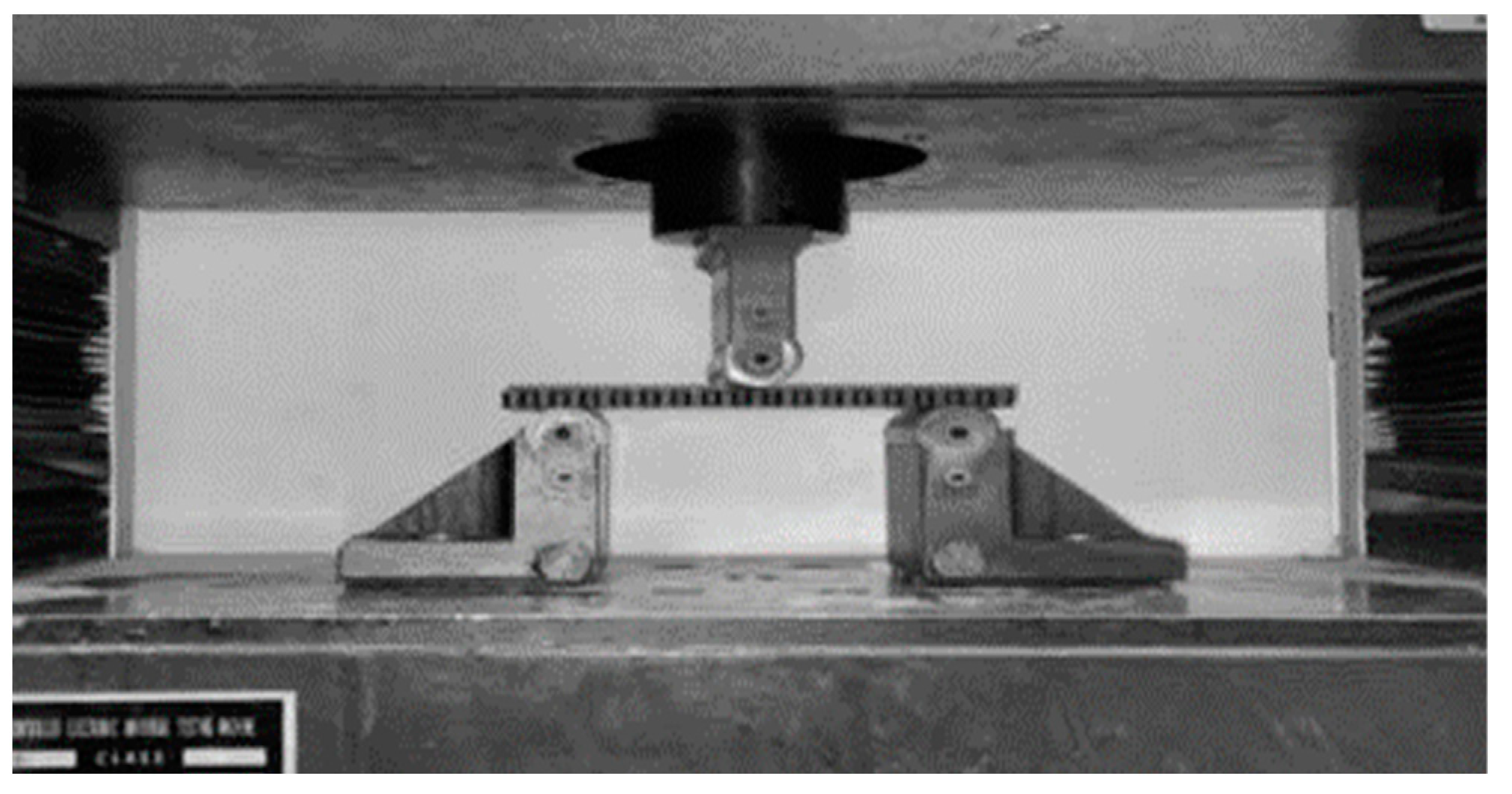
The three-point bending tests were performed according to ASTM C393 using a servo-hydraulic universal testing machine model WDW-200E (TIME Group Inc., Beijing, China) (Figure 2). Tests were performed at the standard crosshead displacement speed of 6 mm/min.
Table 3 presents the nominal dimensions and values of the different specimen types, including the fiber volume fraction in the facing, both total (Vr) and that of fibers oriented longitudinally (Vro).

3. Results

3.1. Mechanical Behavior of CFRC Sandwich Panels with Honeycomb Cores

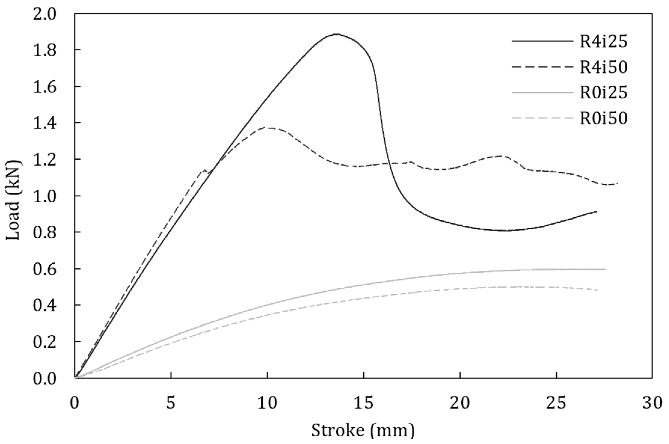
The load–displacement curves of representative specimens for each sandwich type are shown in Figure 3. The behavior of the panels differs significantly based on the presence of reinforcement and core density. In non-reinforced samples, the load rises gradually until it reaches a maximum load, followed by a gradual decrease. On the other hand, in reinforced specimens, the load reached a higher peak value, followed by a rapid decline and stabilization. This suggests a localized failure mechanism, in which a region inside the panel quickly loses its load-bearing capacity once failure begins.
While the drop in the low-density reinforced specimens (R4i25) is steep, in those with a higher core density (R4i50), the decline is less marked and small jumps are noticeable. These oscillations could indicate progressive damage, suggesting a more gradual failure mechanism.
Figure 4 compares the mechanical performance of reinforced and non-reinforced CFRC sandwich panels. The maximum load and flexural modulus are presented in Figure 4a,b. There is noticeable dispersion in the data, especially for the higher core density CFRC specimens (R4i50). This indicates variability in the performance, which could be due to structural inconsistencies. Hence, in addition to the average value, the range (minimum and maximum values) is shown in the figures.
The maximum load in reinforced specimens (R4 vs. R0) was approximately 2.5 times larger than that of non-reinforced samples. The improvement in mechanical properties compared to non-reinforced samples is significant, and on par with previous reports when differences in fiber volume fraction are considered [37]. Similarly, the equivalent flexural modulus of CFRC specimens is around 3 to 4 times that of non-reinforced samples. This is also consistent with previous studies that compared the shear strength of solid polymer composites unreinforced and reinforced with continuous fiber [57].
On the other hand, results for the effect of infill density are counterintuitive: an increase in core density led to a 30% decrease in the critical load (Figure 3) and maximum facing stress (Figure 4c) in CFRC samples. A higher core density is expected to enhance the mechanical performance (strength and stiffness) of sandwich panels [21,58]. The same behavior is also observed in non-reinforced specimens, with better mechanical properties in low-density core samples.
However, this is not the first instance of a non-proportional relationship between infill density and flexural properties. Baich et al. [59] reported a decrease in flexural strength in specimens with larger infill densities, and an unclear correlation between infill density and flexural modulus. A different interpretation of the results is that the high-density core sandwich specimens underperformed due to imperfections in the samples, an idea that we will revisit later.
The facing stress at the midspan in the reinforced and non-reinforced specimens (Figure 4c) mirrors the behavior of Pmax (Figure 4a). The core shear ultimate stress was not calculated because the failure in all specimens occurred in the facing.
A comparison of the flexural modulus obtained using analytical models (Equations (6) and (7)) and experiments is presented in Table 4. The analytical model proposed by Tolf and Clarin (Equation (7)) had a worse performance overall, especially in non-reinforced samples with a high-density core (R0i25).
On the other hand, the model based on the equivalent homogeneous material (Equation (6)) had a relative error of approximately 20% in three cases, although the error was significantly larger for non-reinforced samples with a high-density core (R0i50). This is consistent with our previous observations suggesting that samples with a higher-density core underperformed when compared to the expected values.
The different success rates of the analytical models can be explained by the assumptions made in both models. The equivalent homogeneous material model (Equation (6)) only considers the properties of the facing and assumes that the load-bearing contribution of the core is negligible. Hence, the core density does influence the flexural modulus, especially in reinforced specimens due to the high stiffness of the glass fiber reinforcement. The validity of this assumption is consistent with the experimental results for fiber-reinforced samples, whose average values are about 2% apart.
On the other hand, the model proposed by Tolf and Clarin, which considers the stiffness of the core, fails in predicting the elastic modulus in all but one case, which suggests that the role of the core could be secondary. In this model, the contribution of the core to the total value of the elastic modulus represents between 10% and 30, depending on its density.

3.2. Failure Analysis of CFRC Sandwich Panels with Honeycomb Cores

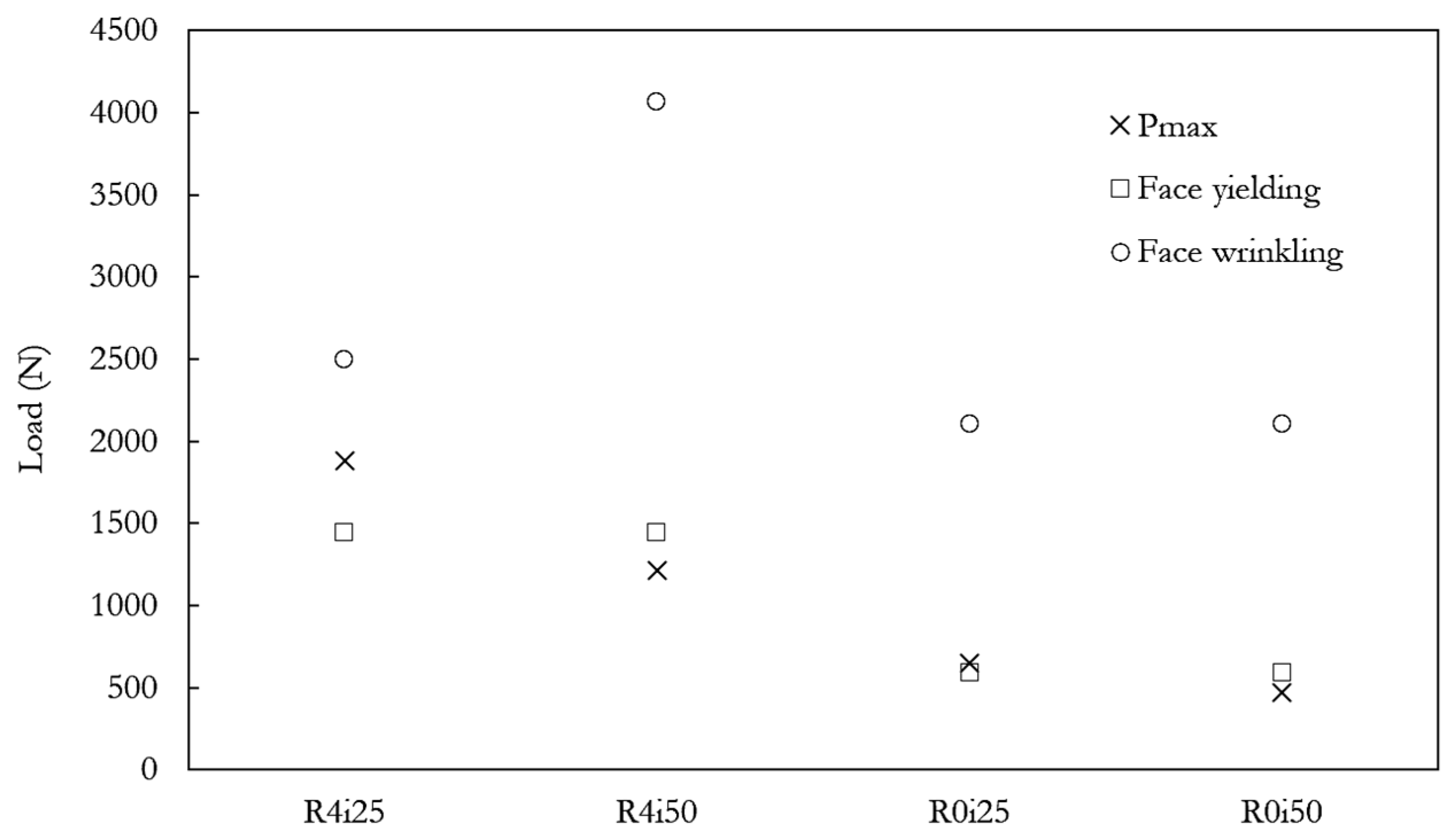
The average maximum load for reinforced and non-reinforced specimens was compared with the critical load values for different failure modes (Figure 5). The figure omits the predicted critical load for bond failure (Equation (13)), which was 2.5 to 11 times larger than the recorded load values. Some of the reinforced and non-reinforced specimens failed by face yielding, but the model only predicted it correctly in specimens with a 25% core density and overestimated the face-yielding load by ~20% in samples with a 50% core density.
The overprediction in the critical load for wrinkling is consistent with previous studies reporting panels failing at approximately 60% of the theoretical critical load [47]. In the R4i25 samples, wrinkling failure occurs at 75% of the critical load and 30% for R4i50. This gap has been commonly attributed to structural imperfections and irregularities in previous studies. Although the presence of a larger number of defects in the R4i50 samples was considered as an initial hypothesis for the premature failure in R4i50 samples, the presence of other failure mechanisms suggests that fiber-polymer interlayer bonding (and interlaminar shear) is the decisive factor behind the larger gap between analytical and experimental results.
In non-reinforced specimens (R0i25 and R0i50), the predominant failure mode was the fracture of the lower facing, with the crack propagating through the core as displacement increased. This is consistent with the predictions of analytical models and the maximum load recorded for the R0i25 and R0i50 samples. Furthermore, the prevailing failure mechanism is face yielding, followed by the facture of the face under tension.
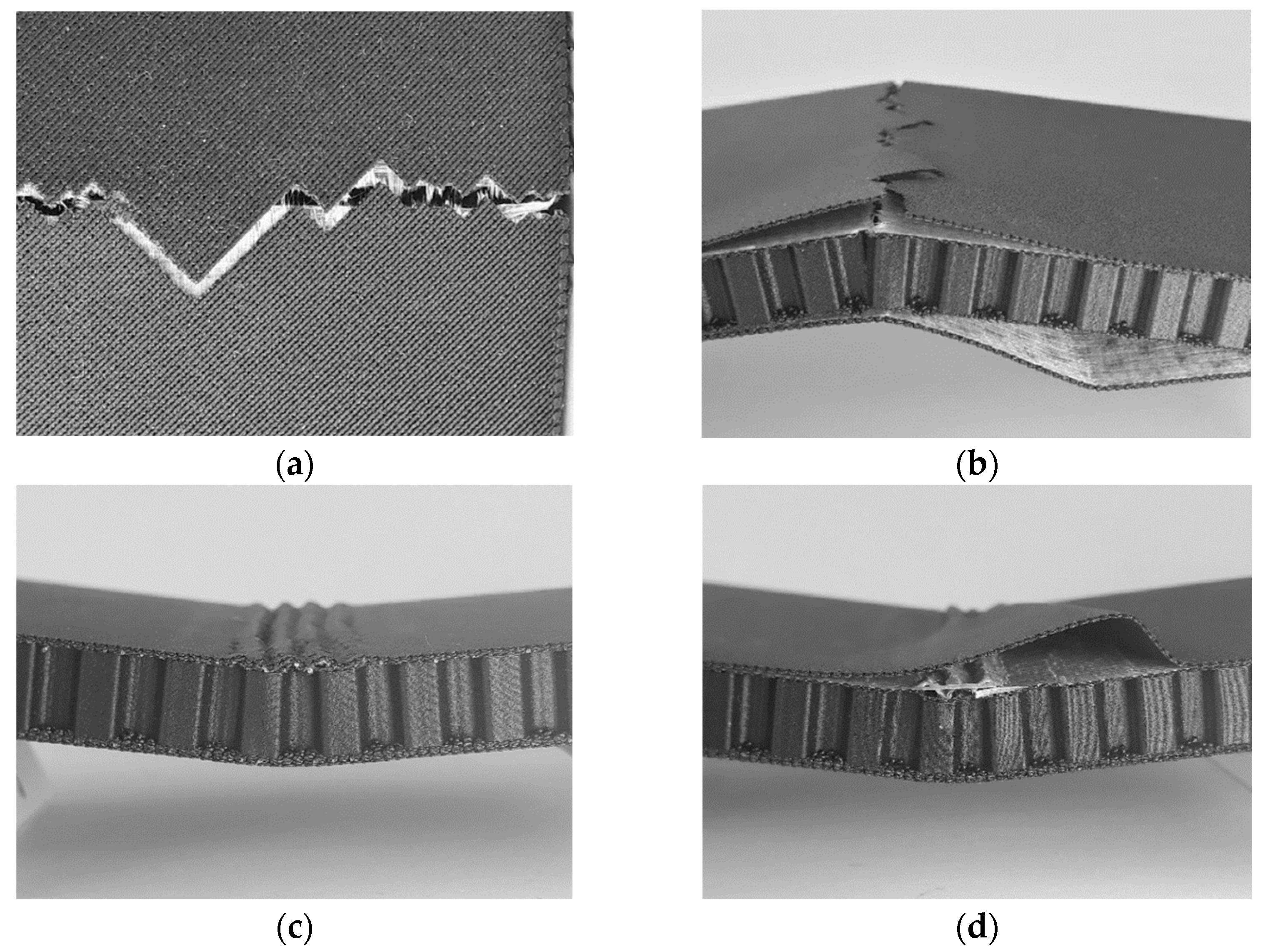
Figure 6 and Figure 7 present the macroscopic appearance of the failure regions in reinforced specimens (R4i25 and R4i50). Samples were photographed after the bending test using a 13 MP digital camera with f/1.9, 28 mm (wide) AF. No postprocessing was required for the samples.
Wrinkling is the prevailing failure mode in the reinforced specimens with low-density cores (Figure 6c,d). The wrinkling/buckling failure mode is common when face thickness and core strength are relatively low [60].
These results diverge from previous studies of additively manufactured CFRC sandwich structures that have reported different failure modes such as fiber pull-out and breakage, delamination, local core crushing, fiber/matrix, and panel/core debonding [43]. On the other hand, the results are consistent with previous studies analyzing the flexural response of CFRC, in which glass fiber specimens did not show failure in tension but rather buckling of fibers in the layers under compression [61]. This difference is understandable, as the latter employed sequential CFRC-FFF—the same technology used to produce the samples in this study—while the former utilized a coaxial system for sample production.
Delamination between the facing and core was also observed in some of the specimens with a higher density core (Figure 6d). The analytical model for facing-core delamination (Equation (13)) significantly overestimated the critical load (2.5×). Delamination can be attributed to interlaminar shear damage and is evident as a sudden drop in the load-displacement curves [62]. Previous authors have suggested that this type of failure could be a consequence of microbuckling in the facing (i.e., wrinkling) [21].
Translaminar cracks are noticeable in one of the R4i25 reinforced samples (Figure 6a), revealing other failure modes present in low density core samples. This failure mode is consistent with the critical load calculated for yield facing (Figure 5). The prevailing failure mechanism was fiber failure; no evidence of fiber/matrix debonding or fiber pullout was observed. After the fiber layer failed, the load was transferred elsewhere, and the crack propagated across the core (Figure 6b). The fracture line in the fiber layer runs perpendicular to the longitudinal axis of the sample, whereas the fracture line in the polymer layer shows a zigzag pattern, with segments oriented at ±45°, the same direction in which the polymer filament is deposited on the layer (Figure 6a).
Similarly, delamination, fracture, and wrinkling can be observed in the R4i50 specimens (Figure 7), confirming that different failure modes are possible, as reported in a previous study [62]. Although no previous reports are available for composite sandwich structures built entirely by AM, facing microbuckling was observed in sandwich structures with fiber-reinforced composite facing and a 3D-printed lattice core [21].
Interlaminar/interlayer debonding between fiber and polymer layers in the facing was the prevailing failure mode in high-density reinforced samples (R4i50) (Figure 7b). No debonding between fiber layers was observed; it was limited to the fiber-polymer interface. In Figure 7b,d, debonding is observed at the top layers (in compression), as reported in [61].
While the fiber-polymer interlayer debonding (Figure 7b,d) could be a result of the shear stresses in the interface, it could also be considered a consequence of microbuckling (i.e., wrinkling). Figure 7d shows that both wrinkling and interlayer debonding are present simultaneously. The non-symmetrical interlayer debonding suggests that this is the result of microbuckling combined with local AM defects in the facing. Previous studies have reported that weak bonding between fiber and polymer layers in glass fiber CFRC combined with a larger number of defects can limit the strength of composite materials [63].
The mechanical behavior of the specimens can be affected by the hygroscopicity of nylon, which is the primary component of Onyx. Although precautions were taken to minimize the influence of humidity on the specimens, environmental changes in the manufacturing and storage conditions could explain the variations between samples [64,65].
Other sources of variability that could explain variations include voids and interlayer imperfections derived from the FFF process, which might change from one specimen to the next. The current limitations of the FFF process significantly influence the mechanical properties, and CFRCs built by FFF are not comparable to those obtained by traditional methods (pre-pregs) [66]. Furthermore, manufacturing defects strongly influence the mechanical response under shear loading, and the mechanical properties are significantly lower [66]. Defects such as intra- and interlaminar voids, non-homogeneous distribution of fibers, and poor interlaminar bonding are expected in parts built by FFF [33,66].

4. Conclusions

Fiber-reinforced specimens showed a 2 to 3-fold increase in strength and elastic modulus compared to non-reinforced samples. On the other hand, a higher infill percentage in lattice beams did not improve the flexural modulus, and both strength and critical load were markedly better in sandwich beams with a low-density core.
Two analytical models for the elastic modulus in sandwich panels were evaluated, with the 3D-printed panel exceeding the predictions of both models. The equivalent homogeneous model had the best performance, with a 20% relative error in CFRC specimens. However, the results for non-reinforced samples with a higher core density were poor. Similarly, analytical models for predicting the critical load in sandwiches were tested. The relative error was around 20% for face yielding, which was present as fiber breakage in a few samples. On the other hand, the analytical model could not correctly predict face wrinkles or interlayer debonding between the polymer and fiber, although this was present in fiber-reinforced samples.
New, better analytical (or numerical) models are needed. Given the limited effectiveness of analytical models, further theoretical and experimental analysis of the wrinkles of sandwich panels is necessary. For instance, the use of classic laminate theory, which has been used to model the mechanical behavior of 3D-printed parts [67,68,69], could be used to predict the mechanical response and failure of this new type of CFRC.
Three damage mechanisms were present: fiber breaking, facing-core delamination, and fiber-polymer interlayer debonding. The interlaminar strength between the matrix and reinforcement layers plays a role in buckling and interlayer debonding. Hence, the effect of interlaminar shear stress on the flexural response of sandwich panels requires further analysis, since previous studies have reported a significant sensitivity to the stacking sequence [70].
Future work could explore the use of other fiber reinforcements (Kevlar and carbon) and the influence of FVF on the bending strength of these composite structures, as suggested in previous reviews for CFRC materials [28]. The effect of pre- and post-treatment processes and a more rigorous dehumidification method for samples should also be investigated, which could help improve interfacial bonding between layers.

Author Contributions

Conceptualization, R.G.S. and G.M.P.; methodology, R.G.S.; validation, R.G.S., E.G. and A.I.; formal analysis, R.G.S., E.G., A.I. and G.M.P.; investigation, R.G.S., E.G. and A.I.; resources, R.G.S. and G.M.P.; data curation, R.G.S., E.G. and A.I.; writing—original draft preparation, R.G.S.; writing—review and editing, R.G.S. and G.M.P.; visualization, R.G.S.; supervision, R.G.S. and G.M.P.; project administration, R.G.S. and G.M.P.; funding acquisition, R.G.S. and G.M.P. All authors have read and agreed to the published version of the manuscript.

Funding

This research was funded by Vicerrectoría de Investigación y Estudios Avanzados (PUCV) grant number 039.357/2021. APC was supported by the Orfalea College of Business (California State Polytechnic University).

Data Availability Statement

Data available on request.

Conflicts of Interest

The authors declare no conflicts of interest.

References

  1. Bhate, D.; Hayduke, D. Architected Cellular Materials. In Additive Manufacturing Design and Applications; ASM International: Materials Park, OH, USA, 2023; pp. 1–10. [Google Scholar]
  2. Cuan-Urquizo, E.; Guerra Silva, R. Fused Filament Fabrication of Cellular, Lattice and Porous Mechanical Metamaterials: A Review. Virtual Phys. Prototyp. 2023, 18, e2224300. [Google Scholar] [CrossRef]
  3. Bru, J.; Leite, M.; Ribeiro, A.R.; Reis, L.; Deus, A.M.; Fátima Vaz, M. Bioinspired Structures for Core Sandwich Composites Produced by Fused Deposition Modelling. Proc. Inst. Mech. Eng. Part L J. Mater. Des. Appl. 2020, 234, 379–393. [Google Scholar] [CrossRef]
  4. Monteiro, J.G.; Sardinha, M.; Alves, F.; Ribeiro, A.R.; Reis, L.; Deus, A.M.; Leite, M.; Vaz, M.F. Evaluation of the Effect of Core Lattice Topology on the Properties of Sandwich Panels Produced by Additive Manufacturing. Proc. Inst. Mech. Eng. Part L J. Mater. Des. Appl. 2020, 235, 1312–1324. [Google Scholar] [CrossRef]
  5. Antony, S.; Cherouat, A.; Montay, G. Fabrication and Characterization of Hemp Fibre Based 3D Printed Honeycomb Sandwich Structure by FDM Process. Appl. Compos. Mater. 2020, 27, 935–953. [Google Scholar] [CrossRef]
  6. Araújo, H.; Leite, M.; Ribeiro, A.R.; Deus, A.M.; Reis, L.; Vaz, M.F. The Effect of Geometry on the Flexural Properties of Cellular Core Structures. Proc. Inst. Mech. Eng. Part L J. Mater. Des. Appl. 2019, 233, 338–347. [Google Scholar] [CrossRef]
  7. Brischetto, S.; Torre, R. Honeycomb Sandwich Specimens Made of PLA and Produced Via 3D FDM Printing Process: An Experimental Study. J. Aircr. Spacecr. Technol. 2020, 4, 54–69. [Google Scholar] [CrossRef]
  8. Brischetto, S.; Ferro, C.G.; Torre, R.; Maggiore, P. 3D FDM Production and Mechanical Behavior of Polymeric Sandwich Specimens Embedding Classical and Honeycomb Cores. Curved Layer. Struct. 2018, 5, 80–94. [Google Scholar] [CrossRef]
  9. Gullapalli, H.; Massod, S.H.; Riza, S.; Ponnusamy, P. Flexural Behaviour of 2D Cellular Lattice Structures Manufactured by Fused Deposition Modelling. In Advances in Structures, Systems and Materials; Springer: Singapore, 2020; pp. 109–117. [Google Scholar]
  10. Gajdoš, I.; Kaščák, L.; Spišák, E.; Slota, J. Flexural Properties of FDM Prototypes Made with Honeycomb and Sparse Structure. Key Eng. Mater. 2015, 635, 169–173. [Google Scholar] [CrossRef]
  11. Beloshenko, V.; Beygelzimer, Y.; Chishko, V.; Savchenko, B.; Sova, N.; Verbylo, D.; Voznyak, A.; Vozniak, I. Mechanical Properties of Flexible Tpu-Based 3d Printed Lattice Structures: Role of Lattice Cut Direction and Architecture. Polymers 2021, 13, 2986. [Google Scholar] [CrossRef]
  12. Essassi, K.; Rebiere, J.L.; El Mahi, A.; Ben Souf, M.A.; Bouguecha, A.; Haddar, M. Experimental and Analytical Investigation of the Bending Behaviour of 3D-Printed Bio-Based Sandwich Structures Composites with Auxetic Core under Cyclic Fatigue Tests. Compos. Part A Appl. Sci. Manuf. 2020, 131, 105775. [Google Scholar] [CrossRef]
  13. Yazdani Sarvestani, H.; Akbarzadeh, A.H.; Mirbolghasemi, A.; Hermenean, K. 3D Printed Meta-Sandwich Structures: Failure Mechanism, Energy Absorption and Multi-Hit Capability. Mater. Des. 2018, 160, 179–193. [Google Scholar] [CrossRef]
  14. Lu, C.; Qi, M.; Islam, S.; Chen, P.; Gao, S.; Xu, Y.; Yang, X. Mechanical Performance of 3D-Printing Plastic Honeycomb Sandwich Structure. Int. J. Precis. Eng. Manuf. Green. Technol. 2018, 5, 47–54. [Google Scholar] [CrossRef]
  15. Valle, R.; Pincheira, G.; Tuninetti, V.; Fernandez, E.; Uribe-Lam, E. Design and Characterization of Asymmetric Cell Structure of Auxetic Material for Predictable Directional Mechanical Response. Materials 2022, 15, 1841. [Google Scholar] [CrossRef]
  16. Hou, Y.; Tai, Y.H.; Lira, C.; Scarpa, F.; Yates, J.R.; Gu, B. The Bending and Failure of Sandwich Structures with Auxetic Gradient Cellular Cores. Compos. Part A Appl. Sci. Manuf. 2013, 49, 119–131. [Google Scholar] [CrossRef]
  17. Cao, D.; Bouzolin, D.; Lu, H.; Griffith, D.T. Bending and Shear Improvements in 3D-Printed Core Sandwich Composites through Modification of Resin Uptake in the Skin/Core Interphase Region. Compos. B Eng. 2023, 264, 110912. [Google Scholar] [CrossRef]
  18. Travieso-Rodriguez, J.A.; Zandi, M.D.; Jerez-Mesa, R.; Lluma-Fuentes, J. Fatigue Behavior of PLA-Wood Composite Manufactured by Fused Filament Fabrication. J. Mater. Res. Technol. 2020, 9, 8507–8516. [Google Scholar] [CrossRef]
  19. Dong, Y.; Milentis, J.; Pramanik, A. Additive Manufacturing of Mechanical Testing Samples Based on Virgin Poly (Lactic Acid) (PLA) and PLA/Wood Fibre Composites. Adv. Manuf. 2018, 6, 71–82. [Google Scholar] [CrossRef]
  20. Li, D.; Liao, W.; Dai, N.; Dong, G.; Tang, Y.; Xie, Y.M. Optimal Design and Modeling of Gyroid-Based Functionally Graded Cellular Structures for Additive Manufacturing. Comput.-Aided Des. 2018, 104, 87–99. [Google Scholar] [CrossRef]
  21. Forés-Garriga, A.; Gómez-Gras, G.; Pérez, M.A. Lightweight Hybrid Composite Sandwich Structures with Additively Manufactured Cellular Cores. Thin-Walled Struct. 2023, 191, 111082. [Google Scholar] [CrossRef]
  22. Ning, F.; Cong, W.; Qiu, J.; Wei, J.; Wang, S. Additive Manufacturing of Carbon Fiber Reinforced Thermoplastic Composites Using Fused Deposition Modeling. Compos. B Eng. 2015, 80, 369–378. [Google Scholar] [CrossRef]
  23. Dey, A.; Roan Eagle, I.N.; Yodo, N. A Review on Filament Materials for Fused Filament Fabrication. J. Manuf. Mater. Process. 2021, 5, 69. [Google Scholar] [CrossRef]
  24. Ferreira, I.; Machado, M.; Alves, F.; Torres Marques, A. A Review on Fibre Reinforced Composite Printing via FFF. Rapid Prototyp. J. 2019, 25, 972–988. [Google Scholar] [CrossRef]
  25. Penumakala, P.K.; Santo, J.; Thomas, A. A Critical Review on the Fused Deposition Modeling of Thermoplastic Polymer Composites. Compos. B Eng. 2020, 201, 108336. [Google Scholar] [CrossRef]
  26. Cuan-Urquizo, E.; Álvarez-Trejo, A.; Robles Gil, A.; Tejada-Ortigoza, V.; Camposeco-Negrete, C.; Uribe-Lam, E.; Treviño-Quintanilla, C.D. Effective Stiffness of Fused Deposition Modeling Infill Lattice Patterns Made of PLA-Wood Material. Polymers 2022, 14, 337. [Google Scholar] [CrossRef]
  27. Li, J.; Durandet, Y.; Huang, X.; Sun, G.; Ruan, D. Additively Manufactured Fiber-Reinforced Composites: A Review of Mechanical Behavior and Opportunities. J. Mater. Sci. Technol. 2022, 119, 219–244. [Google Scholar] [CrossRef]
  28. Safari, F.; Kami, A.; Abedini, V. 3D Printing of Continuous Fiber Reinforced Composites: A Review of the Processing, Pre- and Post-Processing Effects on Mechanical Properties. Polym. Polym. Compos. 2022, 30, 096739112210987. [Google Scholar] [CrossRef]
  29. Pandelidi, C.; Bateman, S.; Piegert, S.; Hoehner, R.; Kelbassa, I.; Brandt, M. The Technology of Continuous Fibre-Reinforced Polymers: A Review on Extrusion Additive Manufacturing Methods. Int. J. Adv. Manuf. Technol. 2021, 113, 3057–3077. [Google Scholar] [CrossRef]
  30. Cheng, P.; Peng, Y.; Li, S.; Rao, Y.; Le Duigou, A.; Wang, K.; Ahzi, S. 3D Printed Continuous Fiber Reinforced Composite Lightweight Structures: A Review and Outlook. Compos. B Eng. 2023, 250, 110450. [Google Scholar] [CrossRef]
  31. Krajangsawasdi, N.; Blok, L.G.; Hamerton, I.; Longana, M.L.; Woods, B.K.S.; Ivanov, D.S. Fused Deposition Modelling of Fibre Reinforced Polymer Composites: A Parametric Review. J. Compos. Sci. 2021, 5, 29. [Google Scholar] [CrossRef]
  32. Wong, J.; Altassan, A.; Rosen, D.W. Additive Manufacturing of Fiber-Reinforced Polymer Composites: A Technical Review and Status of Design Methodologies. Compos. B Eng. 2023, 255, 110603. [Google Scholar] [CrossRef]
  33. Kabir, S.M.F.; Mathur, K.; Seyam, A.F.M. A Critical Review on 3D Printed Continuous Fiber-Reinforced Composites: History, Mechanism, Materials and Properties. Compos. Struct. 2020, 232, 111476. [Google Scholar] [CrossRef]
  34. van de Werken, N.; Tekinalp, H.; Khanbolouki, P.; Ozcan, S.; Williams, A.; Tehrani, M. Additively Manufactured Carbon Fiber-Reinforced Composites: State of the Art and Perspective. Addit. Manuf. 2020, 31, 100962. [Google Scholar] [CrossRef]
  35. Adil, S.; Lazoglu, I. A Review on Additive Manufacturing of Carbon Fiber-Reinforced Polymers: Current Methods, Materials, Mechanical Properties, Applications and Challenges. J. Appl. Polym. Sci. 2023, 140, e53476. [Google Scholar] [CrossRef]
  36. Rimkus, A.; Farh, M.M.; Gribniak, V. Continuously Reinforced Polymeric Composite for Additive Manufacturing—Development and Efficiency Analysis. Polymers 2022, 14, 3471. [Google Scholar] [CrossRef]
  37. Justo, J.; Távara, L.; García-Guzmán, L.; París, F. Characterization of 3D Printed Long Fibre Reinforced Composites. Compos. Struct. 2018, 185, 537–548. [Google Scholar] [CrossRef]
  38. Dickson, A.N.; Barry, J.N.; McDonnell, K.A.; Dowling, D.P. Fabrication of Continuous Carbon, Glass and Kevlar Fibre Reinforced Polymer Composites Using Additive Manufacturing. Addit. Manuf. 2017, 16, 146–152. [Google Scholar] [CrossRef]
  39. Pertuz, A.D.; Díaz-Cardona, S.; González-Estrada, O.A. Static and Fatigue Behaviour of Continuous Fibre Reinforced Thermoplastic Composites Manufactured by Fused Deposition Modelling Technique. Int. J. Fatigue 2020, 130, 105275. [Google Scholar] [CrossRef]
  40. Naranjo-Lozada, J.; Ahuett-Garza, H.; Orta-Castañón, P.; Verbeeten, W.M.H.; Sáiz-González, D. Tensile Properties and Failure Behavior of Chopped and Continuous Carbon Fiber Composites Produced by Additive Manufacturing. Addit. Manuf. 2019, 26, 227–241. [Google Scholar] [CrossRef]
  41. Sugiyama, K.; Matsuzaki, R.; Ueda, M.; Todoroki, A.; Hirano, Y. 3D Printing of Composite Sandwich Structures Using Continuous Carbon Fiber and Fiber Tension. Compos. Part A Appl. Sci. Manuf. 2018, 113, 114–121. [Google Scholar] [CrossRef]
  42. An, D.-S.; Kim, T.H.; Lee, E.-H. Analytical and Experimental Investigation into the Relative Influence of Core and Side Parts on Structures Laminated by Fused Deposition Modeling. Int. J. Precis. Eng. Manuf.-Green. Technol. 2021, 8, 13–27. [Google Scholar] [CrossRef]
  43. Feng, J.; Yao, L.; Lyu, Z.; Wu, Z.; Zhang, G.; Zhao, H. Mechanical Properties and Damage Failure of 3D-printed Continuous Carbon Fiber-reinforced Composite Honeycomb Sandwich Structures with Fiber-interleaved Core. Polym. Compos. 2023, 44, 1980–1992. [Google Scholar] [CrossRef]
  44. ASTM C393; Standard Test Method for Core Shear Properties of Sandwich Constructions by Beam Flexure 1. ASM International: Materials Park, OH, USA, 2006.
  45. ASTM D790-17; Standard Test Methods for Flexural Properties of Unreinforced and Reinforced Plastics and Electrical Insulating Materials 1. ASM International: Materials Park, OH, USA, 2017. [CrossRef]
  46. Gibson, L.J.; Ashby, M.F. Cellular Solids: Structure and Properties; Cambridge University Press: Cambridge, UK, 1997; ISBN 9781139878326. [Google Scholar]
  47. Staal, R.A.; Horrigan, D.P.W.; Mallinson, G.D. Wrinkling Stresses in Honeycomb Sandwich Panels Using Discrete and Continuum Core Representations. In Proceedings of the 13th European Conference on Composite Materials; European Society for Composite Materials, Stockholm, Sweden, 2–5 June 2008. [Google Scholar]
  48. Tolf, G.; Clarin, P. Comparison between Flexural and Tensile Modulus of Fibre Composites. Fibre Sci. Technol. 1984, 21, 319–326. [Google Scholar] [CrossRef]
  49. Callister, W. Materials Science and Engineering: An Introduction, 5th ed.; Wiley: New York, NY, USA, 1999. [Google Scholar]
  50. Markforged. An Introductory Guide Carbon Fiber 3D Printing; Markforged: Waltham, MA, USA; Available online: https://3d.markforged.com/carbon-fiber-3d-printing-whitepaper.html (accessed on 5 October 2024).
  51. Markforged Composites—Material Datasheet. Available online: https://static.markforged.com/downloads/composites-data-sheet.pdf (accessed on 21 July 2023).
  52. Saeed, K.; McIlhagger, A.; Harkin-Jones, E.; McGarrigle, C.; Dixon, D.; Ali Shar, M.; McMillan, A.; Archer, E. Characterization of Continuous Carbon Fibre Reinforced 3D Printed Polymer Composites with Varying Fibre Volume Fractions. Compos. Struct. 2022, 282, 115033. [Google Scholar] [CrossRef]
  53. Tekoglu, C.; Onck, P.R. Size Effects in the Mechanical Behavior of Cellular Materials. J. Mater. Sci. 2005, 40, 5911–5917. [Google Scholar] [CrossRef]
  54. Andrews, E.W.; Gioux, G.; Onck, P.; Gibson, L.J. Size Effects in Ductile Cellular Solids. Part II: Experimental Results. Int. J. Mech. Sci. 2001, 43, 701–713. [Google Scholar] [CrossRef]
  55. Tekoglu, C.; Gibson, L.J.; Pardoen, T.; Onck, P.R. Size Effects in Foams: Experiments and Modeling. Prog. Mater. Sci. 2011, 56, 109–138. [Google Scholar] [CrossRef]
  56. Cofaru, N.F.; Pascu, A.; Oleksik, M.; Petruse, R. Tensile Properties of 3D-Printed Continuous-Fiber-Reinforced Plastics. Mater. Plast. 2022, 58, 271–282. [Google Scholar] [CrossRef]
  57. Caminero, M.A.; Chacón, J.M.; García-Moreno, I.; Reverte, J.M. Interlaminar Bonding Performance of 3D Printed Continuous Fibre Reinforced Thermoplastic Composites Using Fused Deposition Modelling. Polym. Test. 2018, 68, 415–423. [Google Scholar] [CrossRef]
  58. Abdullah Aloyaydi, B.; Sivasankaran, S.; Rizk Ammar, H. Influence of Infill Density on Microstructure and Flexural Behavior of 3D Printed PLA Thermoplastic Parts Processed by Fusion Deposition Modeling. AIMS Mater. Sci. 2019, 6, 1033–1048. [Google Scholar] [CrossRef]
  59. Baich, L.; Manogharan, G. Study of Infill Print Parameters on Mechanical Strength and Production Cost-Time of 3D Printed ABS Parts. In Proceedings of the 26th Annual International Solid Freeform Fabrication Symposium—An Additive Manufacturing Conference, SFF 2015, Austin, TX, USA, 10–12 August 2015; pp. 209–218. [Google Scholar]
  60. Ashby, M.F. Designing Hybrid Materials. In Materials Selection in Mechanical Design; Elsevier: Amsterdam, The Netherlands, 2011; pp. 299–340. [Google Scholar]
  61. Goh, G.D.; Dikshit, V.; Nagalingam, A.P.; Goh, G.L.; Agarwala, S.; Sing, S.L.; Wei, J.; Yeong, W.Y. Characterization of Mechanical Properties and Fracture Mode of Additively Manufactured Carbon Fiber and Glass Fiber Reinforced Thermoplastics. Mater. Des. 2018, 137, 79–89. [Google Scholar] [CrossRef]
  62. Caminero, M.A.; Rodríguez, G.P.; Muñoz, V. Effect of Stacking Sequence on Charpy Impact and Flexural Damage Behavior of Composite Laminates. Compos. Struct. 2016, 136, 345–357. [Google Scholar] [CrossRef]
  63. Chacón, J.M.; Caminero, M.A.; Núñez, P.J.; García-Plaza, E.; García-Moreno, I.; Reverte, J.M. Additive Manufacturing of Continuous Fibre Reinforced Thermoplastic Composites Using Fused Deposition Modelling: Effect of Process Parameters on Mechanical Properties. Compos. Sci. Technol. 2019, 181, 107688. [Google Scholar] [CrossRef]
  64. Wang, K.; Chen, Y.; Long, H.; Baghani, M.; Rao, Y.; Peng, Y. Hygrothermal Aging Effects on the Mechanical Properties of 3D Printed Composites with Different Stacking Sequence of Continuous Glass Fiber Layers. Polym. Test. 2021, 100, 107242. [Google Scholar] [CrossRef]
  65. Chabaud, G.; Castro, M.; Denoual, C.; Le Duigou, A. Hygromechanical Properties of 3D Printed Continuous Carbon and Glass Fibre Reinforced Polyamide Composite for Outdoor Structural Applications. Addit. Manuf. 2019, 26, 94–105. [Google Scholar] [CrossRef]
  66. Iragi, M.; Pascual-González, C.; Esnaola, A.; Lopes, C.S.; Aretxabaleta, L. Ply and Interlaminar Behaviours of 3D Printed Continuous Carbon Fibre-Reinforced Thermoplastic Laminates; Effects of Processing Conditions and Microstructure. Addit. Manuf. 2019, 30, 100884. [Google Scholar] [CrossRef]
  67. Somireddy, M.; Singh, C.V.; Czekanski, A. Analysis of the Material Behavior of 3D Printed Laminates Via FFF. Exp. Mech. 2019, 59, 871–881. [Google Scholar] [CrossRef]
  68. Rajpurohit, S.R.; Dave, H.K.; Bodaghi, M. Classical Laminate Theory for Flexural Strength Prediction of FDM 3D Printed PLAs. Mater. Today Proc. 2023. [Google Scholar] [CrossRef]
  69. Saeed, K.; McIlhagger, A.; Harkin-Jones, E.; Kelly, J.; Archer, E. Predication of the In-Plane Mechanical Properties of Continuous Carbon Fibre Reinforced 3D Printed Polymer Composites Using Classical Laminated-Plate Theory. Compos. Struct. 2021, 259, 113226. [Google Scholar] [CrossRef]
  70. Yavas, D.; Zhang, Z.; Liu, Q.; Wu, D. Interlaminar Shear Behavior of Continuous and Short Carbon Fiber Reinforced Polymer Composites Fabricated by Additive Manufacturing. Compos. B Eng. 2021, 204, 108460. [Google Scholar] [CrossRef]
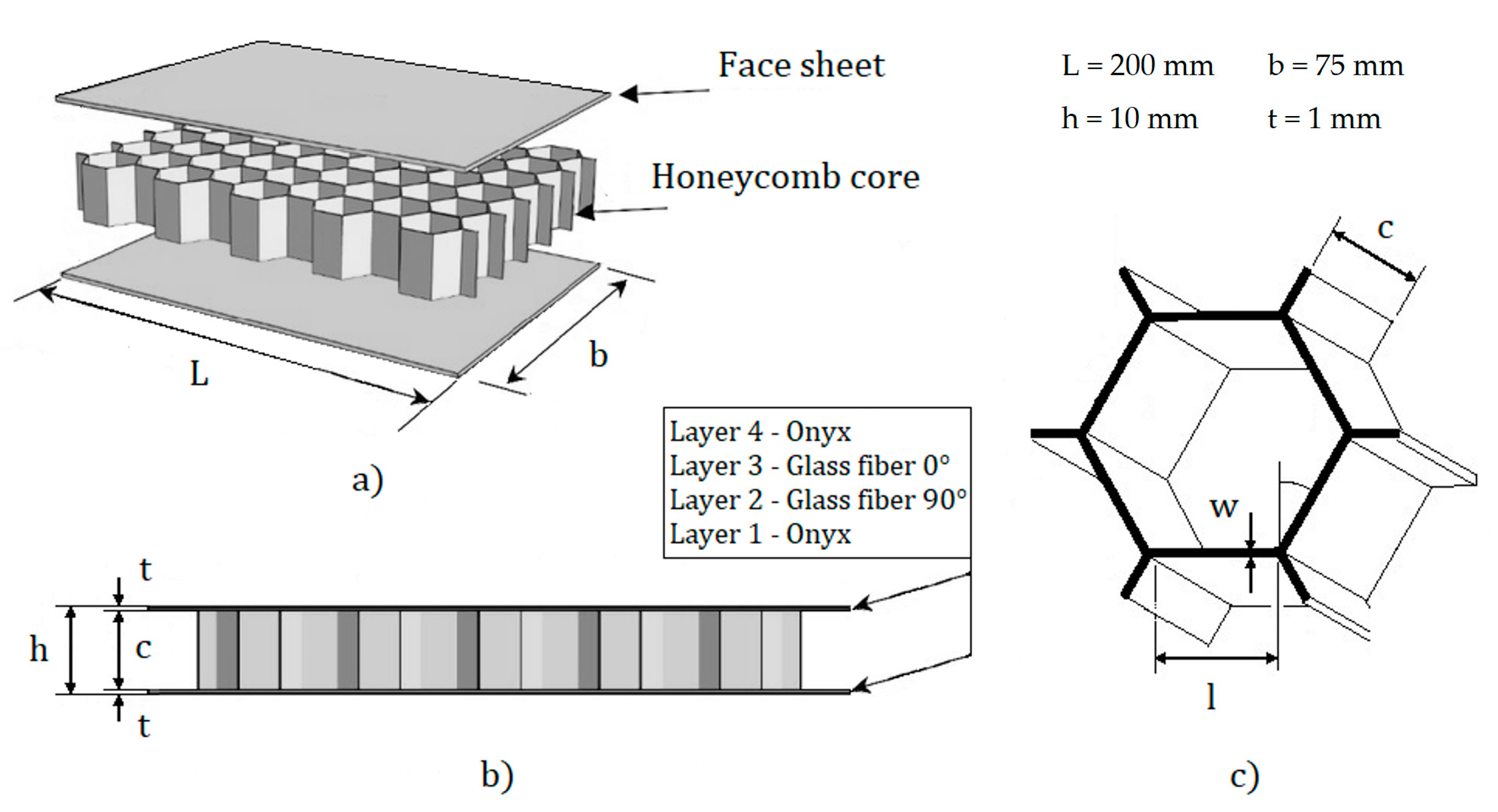
Figure 1. Schematic representation of the dimensions of (a) specimen; (b) face sheet and core (including layer arrangement in sheet); and (c) hexagonal honeycomb.
Jmmp 08 00226 g001
Figure 2. Universal testing machine model TIME WDW-200E with testing specimen.
Jmmp 08 00226 g002
Figure 3. Comparison of force–displacement curves for different specimens for reinforced and non-reinforced sandwich structures.
Jmmp 08 00226 g003
Figure 4. Average and range of (a) maximum load in bending (Pmax); (b) flexural modulus (EB); (c) facing stress (σ), as in Equation (2).
Jmmp 08 00226 g004
Figure 5. Average maximum load before failure in bending (Pmax) and the failure load under face yielding and face wrinkling for reinforced and non-reinforced specimens.
Jmmp 08 00226 g005
Figure 6. Damage in low-density reinforced specimens (R4i25) (a) Fiber breakage in the bottom facing (R4i25-A) (b) Crack across the core (R4i25-A) (c) Wrinkling in the top face (R4i25-B) (d) Delamination between the face and core in the top side (R4i25-C).
Jmmp 08 00226 g006
Figure 7. Damage in high-density reinforced specimens (R4i50) (a) Crack on the lower face (R4i50-B) (b) Crack on the lower face and debonding on the upper face (R4i50-B) (c) Wrinkling on the upper face (R4i50-C) (d) Debonding on the upper face (R4i50-A).
Jmmp 08 00226 g007
Table 1. Printing parameters used to manufacture test specimens.
IDInfill Density
(Core)
Reinforcement Layers (Facing)Fiber Orientation
R4i2525%4 (2 per face)0°/90°
R4i5050%4 (2 per face)0°/90°
R0i2525%0-
R0i5050%0-
Table 2. Mechanical properties of the materials (tested under ASTM D790) [51].
Materialρ (g/cm3)Tensile Strength (MPa)Tensile Modulus (GPa)
Onyx 1.2402.4
Glass fiber 1.559021
Table 3. Geometric, physical, and mechanical properties of the core and facing.
IDl (mm)w (mm)ρc (g/cm3)Ec (GPa)σfc (MPa)VrVr0Ef (GPa)σfy (MPa)
R4i254.171.100.290.1271.860.210.1055.097.8
R4i503.041.400.400.6745.660.210.1055.097.8
R0i254.171.100.290.1271.86--2.440
R0i503.041.400.400.6745.66--2.440
Table 4. Comparison of the experimental and analytical values of the elastic modulus EB (in MPa).
IDExperiment
(Equation (3))
EHM
(Equation (6))
Relative
Error
Tolf and Clarin
(Equation (7))
Relative
Error
R4i251885.1 ± 38.81580.619.3%1127.040.2%
R4i501856.3 ± 197.31580.617.4%1407.224.2%
R0i25666.0 ± 112.2871.423.6%650.42.3%
R0i50463.1 ± 22.7871.446.9%930.7101.0%
Disclaimer/Publisher’s Note: The statements, opinions and data contained in all publications are solely those of the individual author(s) and contributor(s) and not of MDPI and/or the editor(s). MDPI and/or the editor(s) disclaim responsibility for any injury to people or property resulting from any ideas, methods, instructions or products referred to in the content.