Article

Design and Technological Aspects of Integrating Multi-Blade Machining and Surface Hardening on a Single Machine Base

1
Department of Industrial Machinery Design, Novosibirsk State Technical University, 20, K. Marksa Ave., 630073 Novosibirsk, Russia
2
Department of Advanced Technologies, Tomsk Polytechnic University, 30, Lenina Ave., 634050 Tomsk, Russia
*
Author to whom correspondence should be addressed.
J. Manuf. Mater. Process. 2024, 8(5), 200; https://doi.org/10.3390/jmmp8050200
Submission received: 19 August 2024 / Revised: 14 September 2024 / Accepted: 16 September 2024 / Published: 17 September 2024

Abstract

:
Modern mechanical engineering faces high competition in global markets, which requires manufacturers of process equipment to significantly reduce production costs while ensuring high product quality and maximum productivity. Metalworking occupies a significant part of industrial production and consumes a significant share of the world’s energy and natural resources. Improving the technology of manufacturing parts with an emphasis on more efficient use of metalworking machines is necessary to maintain the competitiveness of the domestic machine tool industry. Hybrid metalworking systems based on the principles of multi-purpose integration eliminate the disadvantages of monotechnologies and increase efficiency by reducing time losses and intermediate operations. The purpose of this work is to develop and implement a hybrid machine tool system and an appropriate combined technology for manufacturing machine parts. Theory and methods. Studies of the possible structural composition and layout of hybrid equipment at integration of mechanical and surface-thermal processes were carried out, taking into account the basic provisions of structural synthesis and componentization of metalworking systems. Theoretical studies were carried out using the basic provisions of system analysis, geometric theory of surface formation, design of metalworking machines, methods of finite elements, and mathematical and computer modeling. The mathematical modeling of thermal fields and structural-phase transformations during HEH HFC was carried out in ANSYS (version 19.1) and SYSWELD (version 2010) software packages using numerical methods of solving differential equations of unsteady heat conduction (Fourier equation), carbon diffusion (2nd Fick’s law) and elastic–plastic behavior of the material. The verification of the modeling results was carried out using in situ experiments employing the following: optical and scanning microscopy; and mechanical and X-ray methods of residual stress determination. Formtracer SV-C4500 profilograph profilometer was used in the study for simultaneous measurement of shape deviations and surface roughness. Surface topography was assessed using a Walter UHL VMM 150 V instrumental microscope. The microhardness of the hardened surface layer of the parts was evaluated on a Wolpert Group 402MVD. Results and discussion. The original methodology of structural and kinematic analysis for pre-design studies of hybrid metalworking equipment is presented. Methodological recommendations for the modernization of multi-purpose metal-cutting machine tool are developed, the implementation of which will make it possible to implement high-energy heating with high-frequency currents (HEH HFC) on a standard machine tool system and provide the formation of knowledge-intensive technological equipment with extended functionality. The innovative moment of this work is the development of hybrid metalworking equipment with numerical control and writing a unique postprocessor to it, which allows to realize all functional possibilities of this machine system and the technology of combined processing as a whole. Special tooling and tools providing all the necessary requirements for the process of surface hardening of HEH HFC were designed and manufactured. The conducted complex of works and approbation of the technology of integrated processing in real conditions in comparison with traditional methods of construction of technological process of parts manufacturing allowed to obtain the following results: increase in the productivity of processing by 1.9 times; exclusion of possibility of scrap occurrence at finishing grinding; reduction in auxiliary and preparatory-tasking time; and reduction in inter-operational parts backlogs.

1. Introduction

The contemporary machine tool industry finds itself at a unique juncture, characterized by globalization and intense competition. This environment presents a spectrum of opportunities for growth and innovation, while simultaneously posing considerable challenges to the industry. The main strategic priority of this industry is to combine efforts to reduce production costs, maintain the highest standards of product quality, and achieve maximum performance [1,2,3,4,5,6,7]. Maintaining the competitiveness of products requires ensuring high efficiency in resource and energy conservation, as well as the use of modern machinery that provides flexibility, high performance, and quality of finished products [8,9,10,11,12,13].
In industrialized countries, the share of metalworking products is about 35–40% of total production. The manufacturing sector consumes about 40% of the world’s energy and 25% of its natural resources [8,9,14]. Clearly, sustainable growth is only feasible when negative environmental impacts are reduced, energy and resources are conserved, and the safety of workers and consumers is guaranteed. Modern standards impose high requirements on product characteristics such as wear resistance, fatigue strength, anti-corrosion properties, accuracy, and reliability [7,14,15,16,17,18,19,20]. Worldwide experience shows that a stable position in the market is determined by manufacturing processes and equipment that can guarantee consistent product quality. Therefore, it is necessary to improve the manufacturing technology for individual parts, with an emphasis on the dimensions and shape precision as well as the physical and mechanical properties of the surface layer. The effective use of metalworking machines plays a key role here [8,14,20,21,22,23,24,25,26,27,28,29].
During the shift from large-scale production to the manufacture of smaller series with a greater variety of dimension-type parts, there is a need for the introduction of integrated, flexible, and reliable machining processes, with an emphasis on finishing operations [11,15,30,31,32,33,34,35,36,37,38,39,40,41,42,43,44,45,46,47,48,49]. Many parts and assemblies of mechanisms operate under multifactorial external influences, with the surface layer of parts accumulating defects and stress concentrators. This determines the requirements for their surface fatigue strength and wear resistance. In modern conditions, when most parts work under cyclic contact loading, ensuring their reliable and stable operation becomes a key task of mechanical engineering. The local application of the load and a significant stress gradient in the surface layer determine the specifics of this process and its effect on fatigue strength [8,12,14,20].
One of the most promising areas for improving the reliability of parts is the use of materials that provide high strength and stiffness to the main structure and the required tribotechnical properties of the surface layer. The high failure rate of products associated with surface layer destruction highlights the necessity for surface layer hardening. This is achieved by forming structures in the surface layer characterized by an optimal combination of high strength and viscosity [8,12,14,20,29,50].
Progress in surface hardening is associated with the use of concentrated energy sources such as plasma, lasers, electron beams, and high-energy heating with high-frequency currents (HEH HFC). Local and ultra-high-speed thermal effects make it possible to achieve high levels of hardness, strength, and viscosity due to the formation of a highly dispersed metastable structure [8,12,14,20].
Modern mechanical engineering seeks to integrate different production processes, which has led to the development of multi-purpose machine tools and specialized machines for thermal hardening. However, the traditional separation of surface heat treatment and finishing machining processes increases cost and reduces efficiency. Precise control over the manufacturing processes, minimization of interoperative allowances, and high-quality execution of each stage of the process are critically important for the economic efficiency and high quality of the final products [8,12,14,20,29,39,50].
The development of hybrid machining is driven by the need to increase the potential of machine tools by performing several types of technological operations simultaneously. Hybrid metalworking systems (HMS), which are based on the principle of multifunctional integration, occupy a leading position among combined processing equipment. The integration of various energy sources and processing methods into one machine tool complex makes it possible to eliminate the disadvantages of monotechnologies, creating new effects that are unattainable with their separate applications. The efficiency of combined technologies is achieved by reducing time losses and the number of intermediate operations. Technical and economic analysis shows that hybrid systems can replace several traditional machine tools, integrating production processes in terms of spatial and cyclic organization [8,10,11,12,14,19,20,29,50].
The main directions for the development of process equipment for integrated methods include the modernization of existing machines and the development of new specialized equipment. Due to globalization and the growing demands of the modern market, modernization involves rapid improvements at minimal cost, helping to boost the efficiency and competitiveness of the engineering industry [8,10,11,12,14,19,20,29,50].
The object of this study is the process of manufacturing machine parts based on the use of HMS. This hybrid equipment combines mechanical processing (milling and grinding) and surface heat treatment (HEH HFC). These types of processing can be performed sequentially or simultaneously, which significantly increases the efficiency and flexibility of the production process.
The purpose of this work is to develop and implement a hybrid machine tool system and an appropriate combined technology for manufacturing machine parts. To achieve this purpose, the following tasks must be solved:
  • Develop a scheme for upgrading standard process equipment to the level of HMS using the methods of structural and kinematic synthesis, principles of machine tool layout, and mathematical simulation of the operating loads of the machine tool system.
  • Test a metalworking machine tool complex employing hybrid processing technology at a production facility to confirm the effectiveness of its implementation in the production process.

2. Materials and Methods

The working motions of the hybrid metalworking system (HMS) and the corresponding parameters of their settings were determined using structural and kinematic analysis of metal-cutting machines [8,20,51,52,53,54]. The research was based on the theoretical principles of structural synthesis and system layout presented in [8,20,51,52,53,54]. These provisions were used to develop the final HMS layout, which integrates surface heat treatment and mechanical operations.
A universal method of mathematical simulation of complex machine tool specifications was applied to solve the problem of calculating the operational loads of a hybrid metalworking system [8,20,47].
The provisions of dimensional chain theory and the methods described in specialized works [55,56] were used to determine the linear operational dimensions with the required depth of the thermally strengthened layer.
The process of simulation of hybrid machining and preparation of the control program for a multi-purpose CNC machine was carried out in the PowerMILL CAM system.

2.1. Materials and Methods of Field Experiments

Field experiments were performed using a press brake punch [8] (Figure 1) made of U8A steel (Table 1). The composition of the initial material was determined using an ARL 3460 optical emission spectrometer.
The experiments were performed on MS032.06, an upgraded multi-purpose processing center equipped with an additional energy source, SVCh-10 (UralInduktor, Miass, Russia), a thyristor-type ultra-high-frequency generator with an operating current frequency of 100–440 kHz, for implementing high-energy heating with high-frequency currents. A Hantek DSO 1000S (Qingdao Hantek Electronic Co., Ltd., Qingdao, Shandong, China) Series digital oscilloscope was used to measure and control the operating frequency of the induction heater [8,12].
Structural studies of the samples were carried out using a Carl Zeiss Axio Observer Z1m (ZEISS, Köln, Germany) optical microscope and a Carl Zeiss EVO 50 XVP scanning electron microscope (ZEISS, Köln, Germany), which is equipped with an INCA X-ACT energy dispersion analyzer (Oxford Instruments, Wiesbaden, Germany). The microstructure of the samples was detected using a 5% alcoholic solution of nitric acid and a saturated solution of picric acid in ethyl alcohol with the addition of surfactants [8,57].
The microhardness of the hardened surface layer was evaluated using the Wolpert Group 402MVD device (Yumpu, Diepoldsau, Switzerland). Residual stress studies were performed using the X-ray method on a high-resolution ARL X’TRA diffractometer, as well as using a mechanical destructive method of layered electrolytic etching of the sample [12,58,59]. To identify defects in the surface layer, a series of methods were employed at each stage of the process. These included the visual-optical method using a Carl Zeiss Axio Observer A1m microscope (ZEISS, Köln, Germany), the capillary method, and the current-excitation method using a VD-70 eddy current flaw detector (ANK, Ltd., Moscow, Russia) [12].
Precision studies of macro- and microgeometry, as well as surface topography, were performed on a Formtracer SV-C4500 (Mitutoyo Corp., Kawasaki-shi, Kanagawa, Japan) contour profilometer and a Walter UHL VMM 150 V instrumental microscope (Walter Uhl technische Mikroskopie GmbH & Co. KG, Asslar, Germany).
Statistical processing of experimental research results was performed in Statistica 6.0 (StatSoft, Tulsa, OK, USA), Table Curve 2D v 4.0 (Merck, Darmstadt, Germany) and Table Curve 3D v 4.0 (Merck, Darmstadt, Germany) software products.

2.2. Mathematical Simulation of Thermal Fields, Structural-Phase Transformations, and the Stress–Strain State of a Material at HEH HFC

A joint simulation of temperature fields, structural-phase transformations in the material, and the stress–strain state of the part during processing is necessary to determine efficient modes of surface hardening with high-frequency currents under ultra-high-speed high-energy heating requirements [8,12,14,29,39,50].
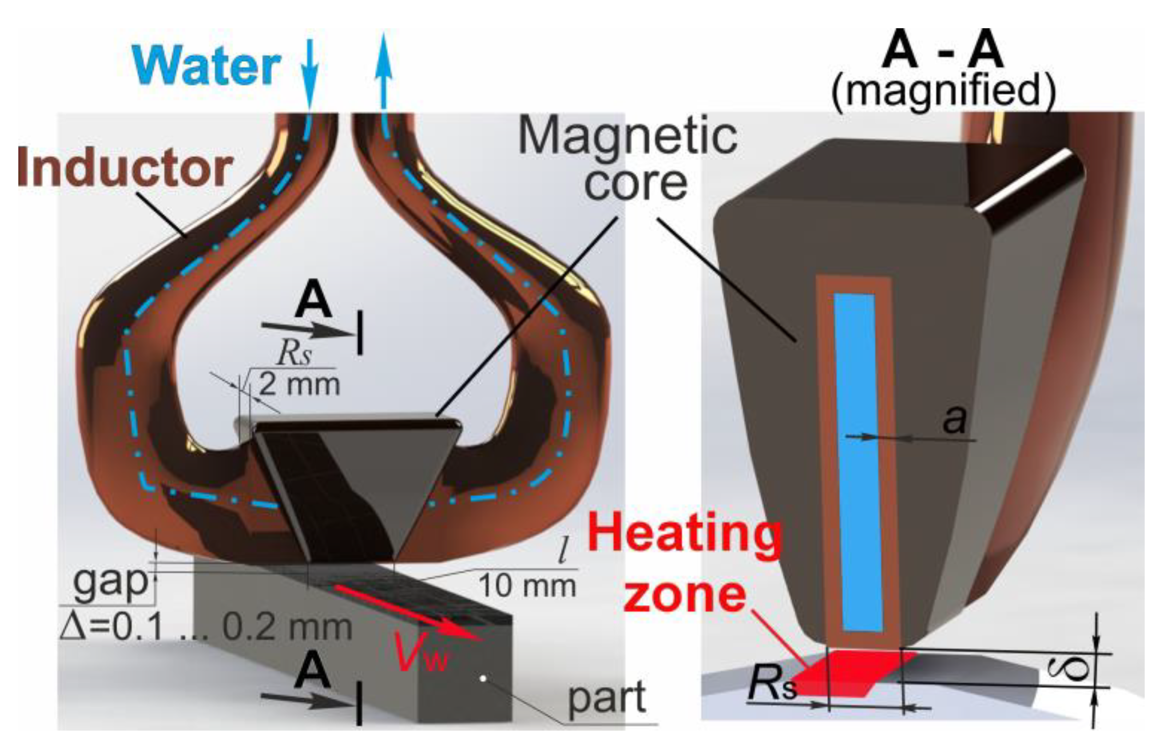
The heating process was carried out according to the depth scheme (the thickness of the hardened layer did not exceed the depth of current penetration into the hot metal—0.6...0.8 mm) in a continuous-sequential way. The processing scheme is shown in Figure 2. A loop-type inductor equipped with a N87 ferrite magnetic core (for operation in the frequency range up to 500 kHz) with a magnetic permeability of μi = 2200 (Figure 2). Studies were carried out using intensive water shower cooling of the surface (heat transfer coefficient α = 30∙103 W/(m2·°C)) in the following range of treatment modes: specific power of the source qS = [1; 4.0]∙108 W/m2, speed of the energy source Vw = [1; 100] mm/s. The width of the inductor active wire was RS = 1…2 mm, processing was carried out with a gap δ = 0.1…0.2 mm. In order to eliminate the possibility of burnout of the active wire and to ensure reliable heat dissipation, the thickness of the inductor walls was a = 0.12...0.15 mm.
The construction of the finite element model took place in the ANSYS and SYSWELD software complexes, which use numerical methods for solving differential equations of transient heat conduction (Fourier equation), carbon diffusion (Fick’s second law), and elastic–plastic behavior of the material [8,12,14,29,39,50].
The preparation of the finite element model was carried out in the ANSYS software package. A hexahedral finite element grid using the following types of finite elements was formed in the ANSYS meshing generator: Solid bodies were modeled by 8-node SOLID 45 tetrahedra; surface bodies were modeled by 4-node quadrangular shell elements SHELL 63; line bodies were modeled by 2-node linear elements LINK 8. The size of the final elements varied from 0.1 to 4 mm.
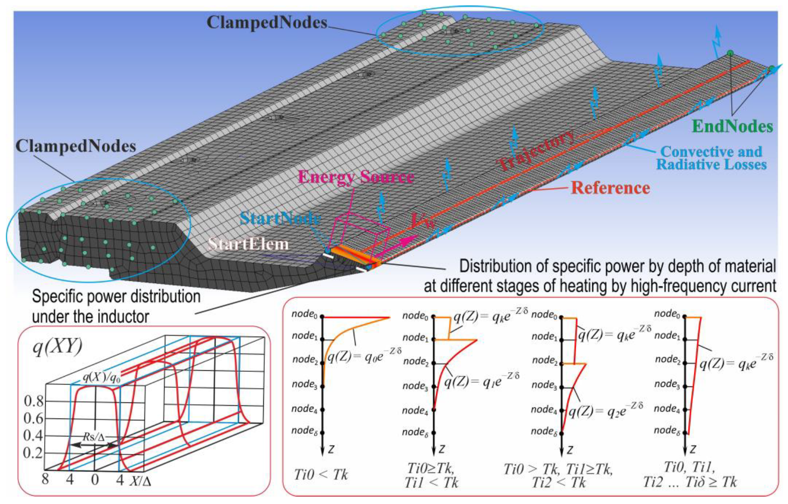
The following components were defined for creating a finite element model. Volume: a group of three-dimensional elements denoting the object being processed. Trajectory: a group of one-dimensional elements determining the trajectory of the energy source’s motion. Reference: a reference equidistant, a group of one-dimensional elements necessary for orienting the local coordinate system of the energy source. StartElem: the starting elements of the beginning of the source action. StartNodes and EndNodes: the initial and final nodes on the trajectory of motion. Skin: a group of two-dimensional elements denoting surfaces along which convective and radiative heat losses occur. ClampedNodes: a group of nodes along which the punch is fixed (Figure 3).
In the case of HF heating, the sources of energy release are eddy currents arising in the material under the influence of alternating magnetic and electric fields. The value of the specific heating power will be determined by the current density J; the character of its change along the metal depth is described by the following dependence:
J Z J O = e Z π μ 0 μ   f ρ e ,
where JZ—current density at depth Z; J0—current density at the surface; ρe—specific electrical resistance; f—current frequency; μ0—absolute magnetic permeability of vacuum; and μ—relative magnetic permeability of material.
When steel is heated, its resistivity and magnetic permeability change, with resistivity increasing up to the point of magnetic transformation, after which its growth slows down. Magnetic permeability weakly depends on temperature approximately up to 650...700 °C, after that it quickly decreases and reaches the value approximately equal to the magnetic permeability of vacuum. It follows from the above that the energy distribution over the depth of the material is not constant.
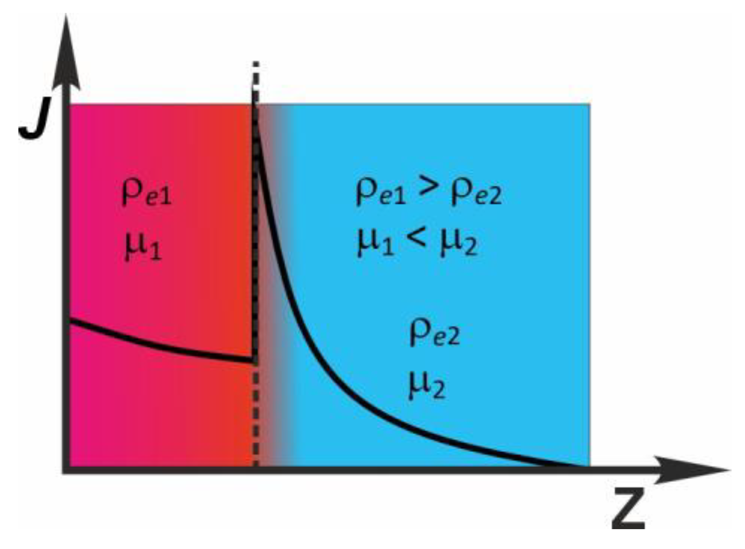
The kinetic curves of heating of the product surface have a kink in the temperature range of 700...800 °C. The heating process is divided into an initial stage with a large almost constant rate of temperature rise and a stage of slow heating above the temperature of steel loss of magnetic properties. The main reason for slow heating at the point of magnetic transformations is the redistribution of energy across the cross-section of the product (Figure 3). Indeed, in the process of heating there is always some temperature gradient created along the cross-section of the processed object. The values ρe and μ depend on the temperature of the material. Thus, the propagation of the electromagnetic process occurs in a medium with variables ρe and μ. In [14,29], a case where the material consists of two layers with different ρe and μ is considered. If the first layer is heated above a temperature of 800 °C and the second layer is not heated (20 °C), the eddy current distribution would exactly correspond to the dependence presented in Figure 4. Consequently, under the condition that the upper layer of the material has lost its ferromagnetic properties, and the underlying layer is heated to a temperature not exceeding the Curie point temperature, there is a redistribution of the current density. The maximum energy release shifts from the surface to the layer that has not lost its ferromagnetic properties.
Thus, an integrated approach that combines the modeling of temperature fields, structural transformations, and mechanical properties of the material resulted in the accurate determination of efficient modes for surface hardening with high-frequency currents.

3. Results and Discussion

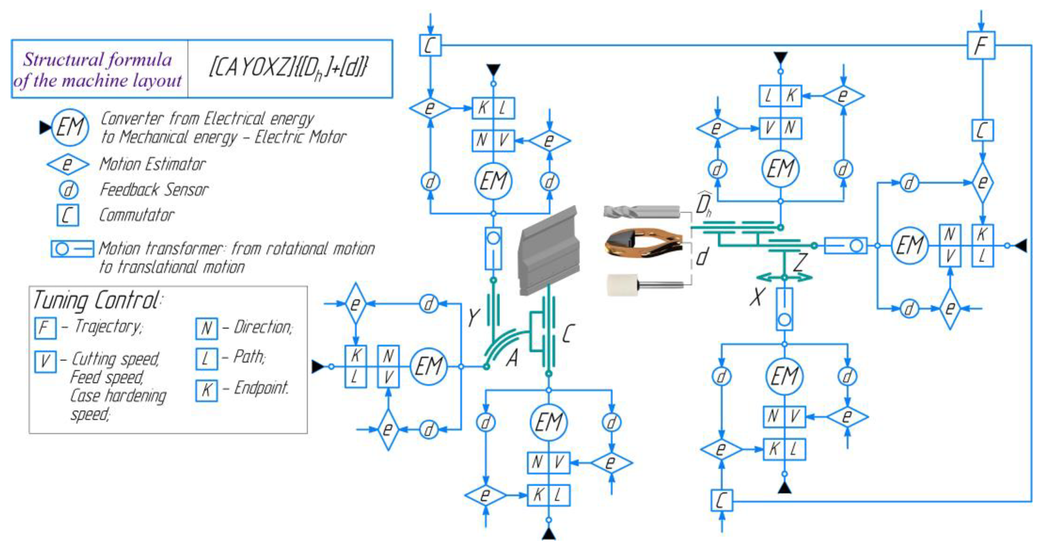
The initial data for the structural and kinematic analysis of the HMS were collected on the basis of the parametric complex characterizing the geometry and quality indicators of the manufactured part (Figure 1). The technological quality assurance in product processing made provisions for two implementation schemes of integrated processing. The difference was in the last transition, where either a cutting tool or an abrasive tool was used. Structural and kinematic analyses have shown that a similar set of working motions and configurable parameters is required at all transitions of the considered integrated processing schemes (preliminary cutting tool processing, high-frequency current hardening, and final cutting tool processing or grinding) [8,20]. Retrofitting the existing process equipment was chosen as a means to accelerate the implementation of a hybrid metalworking system while minimizing implementation costs. The basis of the machine tool system was the MS032.06 five-axis multi-purpose machining center. The synthesis results of the generalized kinematic structure for the developed HMS are shown in Figure 5, with the machine layout formula expressed in the following form:
[ C A Y 0 X Z ] { [ D ^ h ] + [ d ] } ,
where A and C are the rotary axes of the table; Y is the vertical motion of the table with the workpiece; X and Z are linear motions of the tool; D ^ h is the spindle rotation with the cutting tool; d is the rotational movement of the inductor. The block Dh, which performs the main cutting movement during milling, is additionally marked with the sign ∧.
Replacing the standard Fanuc 6M model B CNC system with NC-400 CNC (UEFI) from a leading Russian developer and manufacturer of numerical control devices, OOO Balt-System, ensured the 5-axis high-performance machining of the parts, as well as the possibility of integrating the SVCh-10 ultra-high-frequency thyristor generator control system into the machine tool numerical control device (CNC). Retrofitting of the machine tool system with an additional SVCh-10 energy source with an operating current frequency of 100–440 kHz was necessary to ensure the second transition to surface hardening by HEH HFC during hybrid processing [8,20].
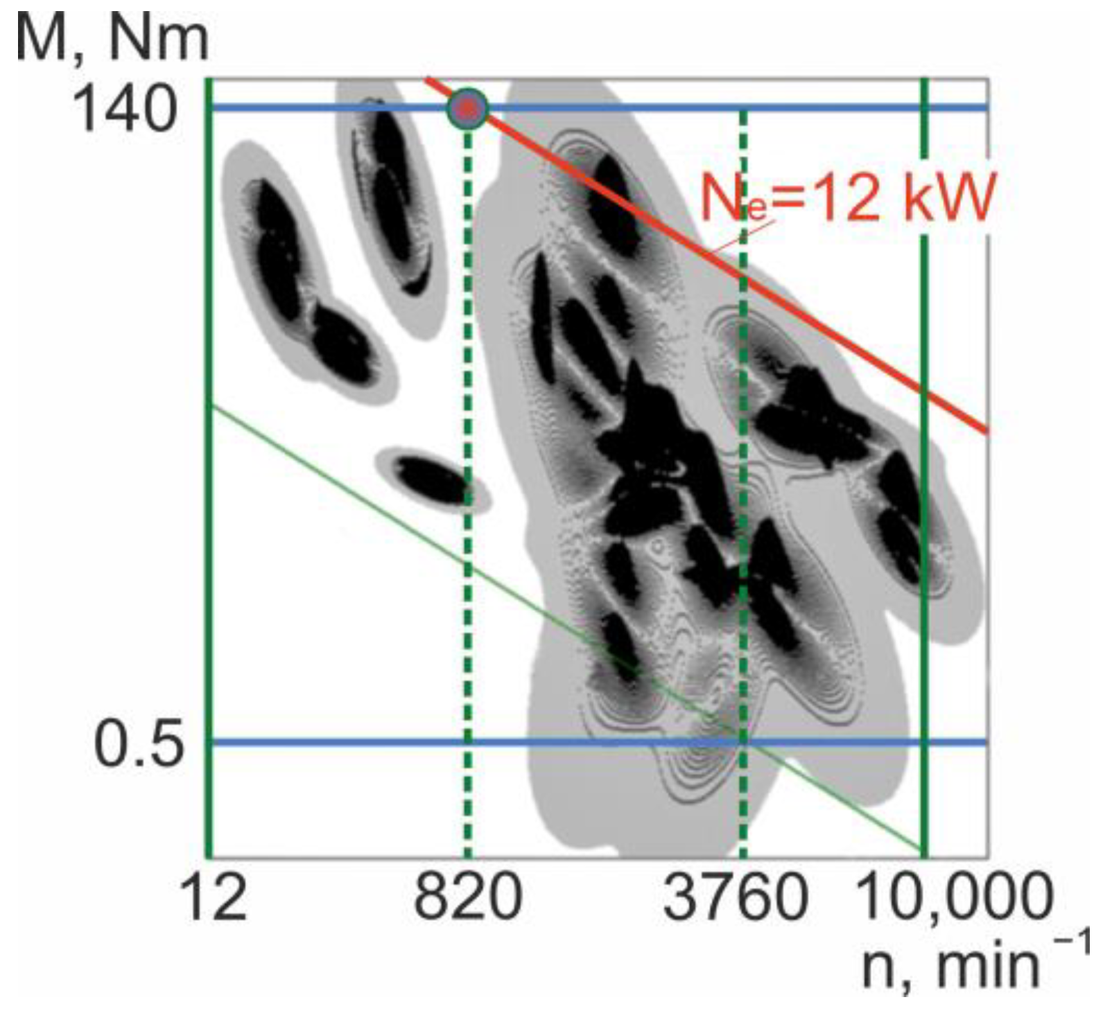
The specifications’ prediction of the developed hybrid machine tool system was performed to ensure the efficient use of process equipment and contemporary cutting tools. The simulation results are shown in Figure 6.
The existing electric drive provides neither the necessary range of speed control nor the specifics of the hybrid metalworking system. The efficiency of the HMS in automatic mode largely depends on the speed and reliability of switching between the modes of integrated operations: mechanical and surface-thermal treatments. Therefore, the main drive was replaced with a 5AI160S2 electric motor with a MD500T18.5G/22PB-PLUS Inovance frequency converter.
The performed works potentially allowed for a significant expansion of the control range of the main motion drive. In the standard configuration of the machine, the spindle speed was in the range of 12–3760 min−1. After the retrofit, the control range was expanded to values n = 12–10,000 min−1. The high-speed cutting and grinding were supposed to be performed in the frequency range of 3760 to 10,000 min−1.
However, the design features of the spindle assembly (Figure 7) impose restrictions on the operation of process equipment in the specified control range. The hollow spindle 1 is fixed to precise angular contact rolling bearings mounted in the lapped holes of the spindle sleeve 2. In the front part, the spindle is fixed in the axes of package 3, consisting of three spindle angular contact bearings of HG accuracy class. The bearings are properly press fitted along the inner diameter (2–3 µm) with clearance along the outer diameter (0–2 µm). The front support is stiff. In the rear part, the spindle is also fixed in the axes of package 4 of two angular contact bearings of the HG accuracy class, similar in size to the front ones. The bearings are properly press fitted along the inner diameter (2–3 µm) with clearance along the outer diameter (0–2 µm). The rear support is floating. An axial force of 9 kN is required to preload five spindle bearings. Spindle bearings are packed with consistent grease and do not require additional lubrication.
The type of bearings, their dimensions and quantity, as well as the method of lubrication, impose a restriction on the speed criterion. Here, it is equal to ndfb = 3·105 mm·min−1. Considering other parameters, such as the diameter of the front bearing journal dfb = 70 mm and the load affecting the bearing, which is estimated by the value of the resource, the maximum permissible spindle speed of nmp is about 4000–4100 min−1 [60]. Increasing the speed by at least two times can be achieved by using precision angular contact ball bearings with rolling elements made of ceramic materials, by providing automatic control of the bearing preload, and by using a more advanced liquid lubrication system.
Given the rather stringent requirements for the precision of the punch working surfaces, there is a high probability of non-compliance with the requirements for microgeometry when using the first hybrid processing scheme. Alternatively, grinding with the required process efficiency can be implemented if sufficiently stringent requirements for the design of the spindle assembly are met to provide a cutting speed of V ≥ 35 m/s. At this stage of work, the technical resources of a standard machine tool system for grinding cannot be used, and a major overhaul of the main drive undermines the economic feasibility of implementing hybrid machining.
The advances in the systems of autonomous, quickly installed high-speed spindles with an air turbine enable the implementation of high-speed machining and grinding processes on lathes, drilling, and milling machines. In the current study, Planet 600 M2040 Jig Grinding Spindle (Nakanishi Inc., Tochigi, Japan) was used during the experiments.
This high-speed energy-saving system, powered by a separate pneumatic actuator (compressor) and allowing for rotational speeds in the range of 50,000–65,000 min−1, was fixed in the main spindle of the MS032.06 machine by means of a standard adjustable boring head. The maximum runout of the Planet 600 M2040 (Nakanishi Inc., Tochigi, Japan) high-speed spindle was within 1 µm.
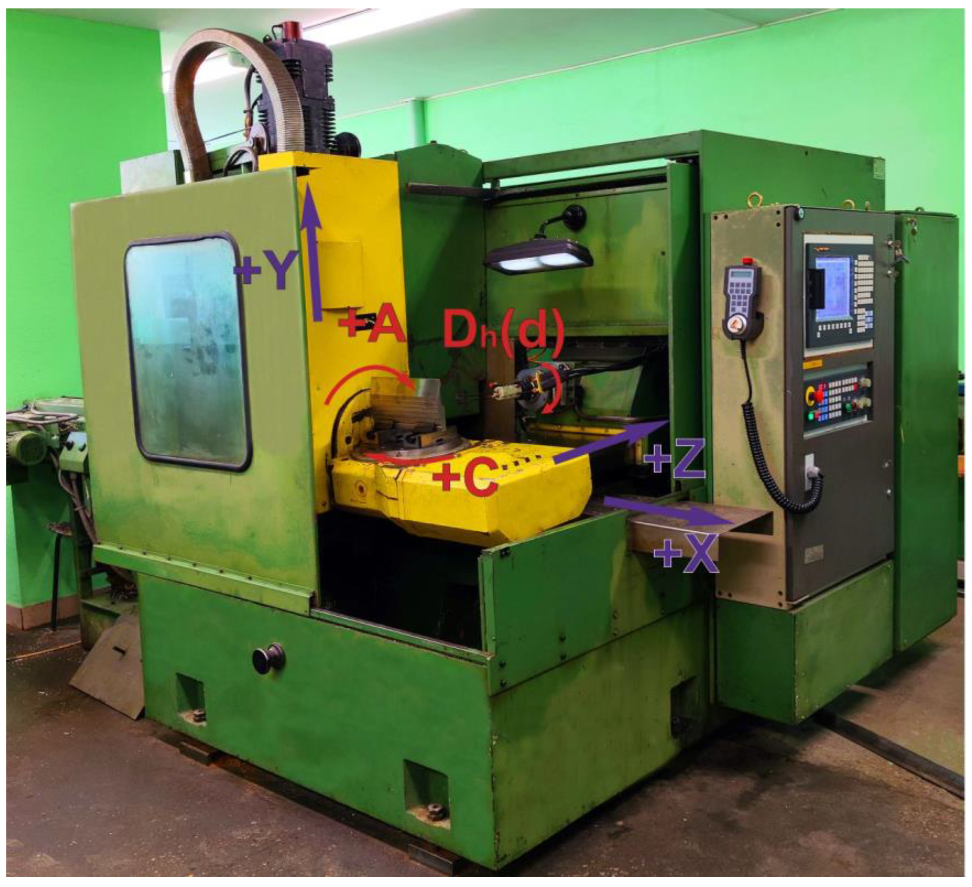
The complex of pre-design studies, retrofit of the main drive, installation of a new CNC system, and development of a program for controlling the machine’s electrical automation made it possible to implement hybrid technological equipment combining mechanical and surface heat treatment (Figure 8).
The process of manufacturing a press brake punch using hybrid metalworking equipment implies certain procedures. The processing of the workpiece was carried out at the upgraded MS032.06 multi-purpose machining center and consisted of three transitions [8]: preliminary (roughing) and finishing mechanical processing, surface hardening by HEH HFC, grinding, and sparking-out.

3.1. Pre-Machining (Milling)

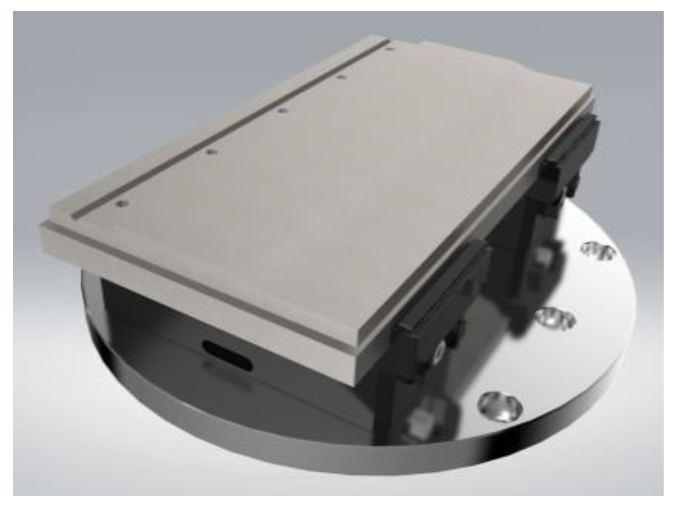
A pair of H77-160 self-centering vices (Figure 9) mounted on the machine table through a transition plate were used as a tool for fixing the workpiece on the machine table.
The first transition is the roughing and finishing milling of the main profile of half of the part. The PE09.11A22.050.05 (CNCM Inc., Barnaul, Russia) end mill used for roughing has a diameter of 50 mm and XOMT11T308-PL (CNCM Inc., Barnaul, Russia) replaceable carbide plates with an edge radius of 0.8 mm made of BPG20B alloy. The recommended and selected cutting modes are shown in Table 2.
The overlapping during milling for machines of this stiffness class is as follows:
A = 0.3·D,
where A is the value of overlapping in millimeters, and D is the diameter of the cutting tool. According to [55,56], the finishing milling allowance is roughly 0.2 mm.
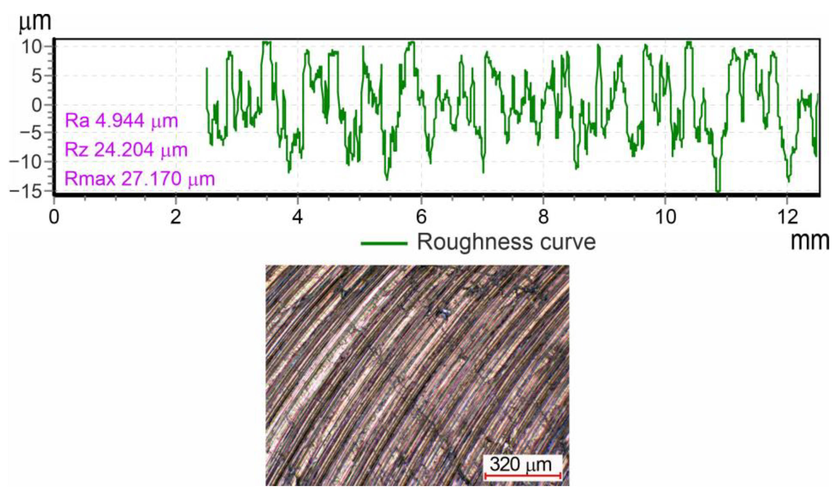
The “3D Model Sampling” trajectory was used for roughing, which allows for constant removal of material and residual surface allowance for finishing. The trajectory parameters were the following. 1. Cut direction (Profile—“Climb”; Area—“Climb”). 2. Tolerance (0.01 mm). 3. Thickness (0.2 mm). 4. Stepover (20.0 mm). 5. Stepdown (Automatic 2.0 mm, constant). Figure 10 shows the roughing trajectory at the first transition and setup of the workpiece. The TECHCOOL 1000 universal lubricating coolant containing mineral oils was used during the machining [8]. Figure 11 shows the profilogram and topography of the surface after rough milling. The experimental data processing revealed the roughness of the treated surface according to the parameters Rz = 25.3 ± 2.19 µm and Ra = 5.14 ± 0.39 µm. The total time spent on roughing at the first transition and setup is 30 min.
The IA21-16-36100-E2 carbide end mill used for finishing the main planes has a 16 mm diameter and a right angle on the edge. This tool is recommended for processing carbon steels in the modes shown in Table 3.
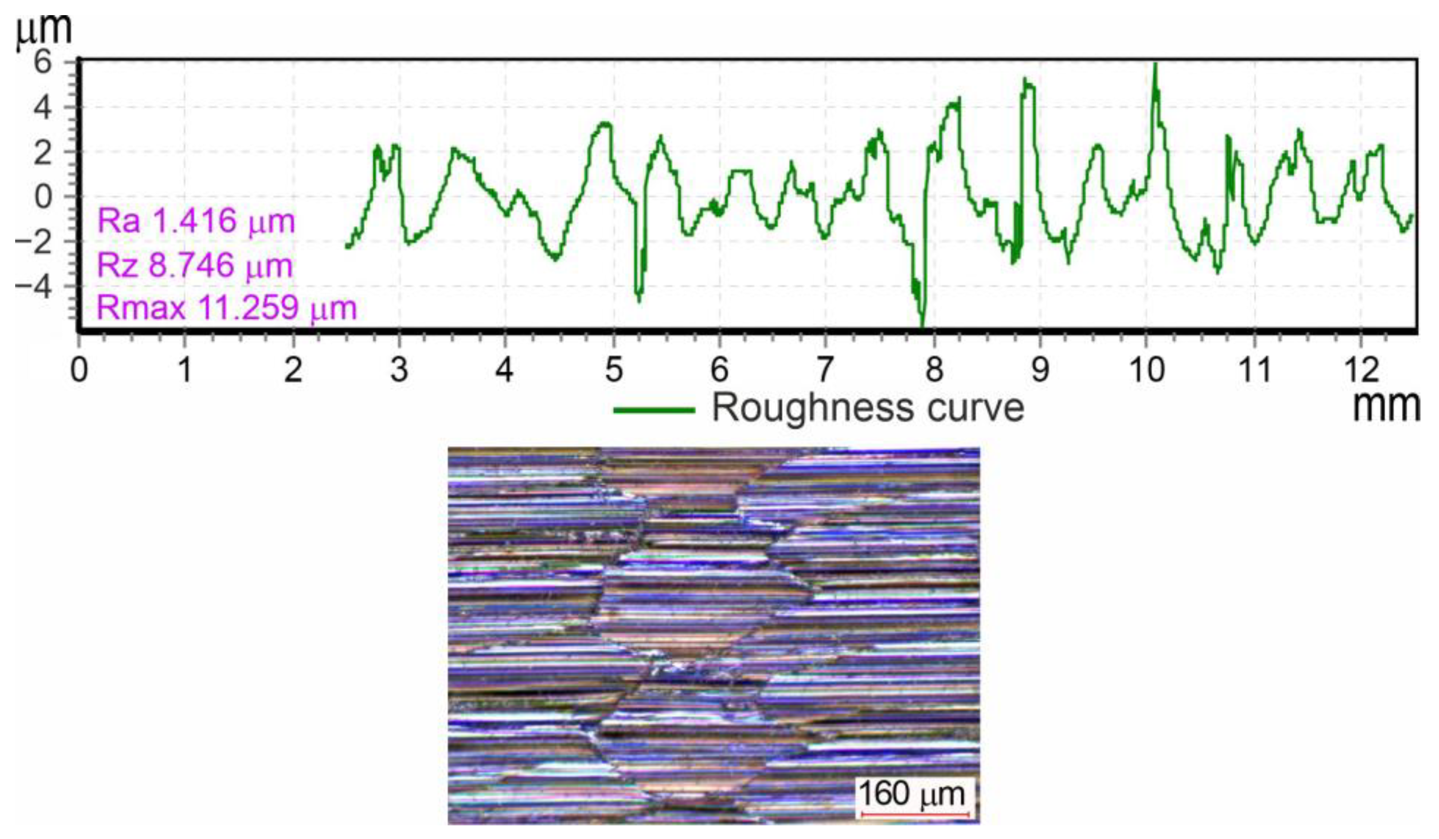
Finishing was carried out according to the “Raster Plane” trajectory using rotary axes. The trajectory parameters were as follows. 1. Flat tolerance (0.1 mm). 2. Approach outside allowance (0.05 mm). 3. Threshold TDU (2.0 mm). 4. Tolerance (0.01 mm). 5. Cut direction (Any). 6. Stepover (10.0 mm). 7. Final stepdown (1.0 mm). Figure 12 shows the strategy of finishing the planes at the first transition and setup. Figure 13 shows the profilogram and topography of the surface after finishing milling. The experimental data processing revealed the roughness of the treated surface according to the parameters Rz = 8.46 ± 2.18 µm and Ra = 1.29 ± 0.31 µm. The time for finishing treatment at the first transition and setup was 20 min. As can be seen, the finishing process significantly improves the quality of the machined surface compared to the previous roughing pass. Thus, the surface roughness values are improved almost four times. It should also be noted that at the finishing pass, to increase productivity the strategy of machining, ‘Raster Plane’ with alternation of counter and cross types of milling was used. The surface topography clearly shows traces of different types of milling.
IA21-02-04050-B4 spherical mill with a diameter of 2 mm was used to process the wedge-shaped groove on the cutting modes shown in Table 4.
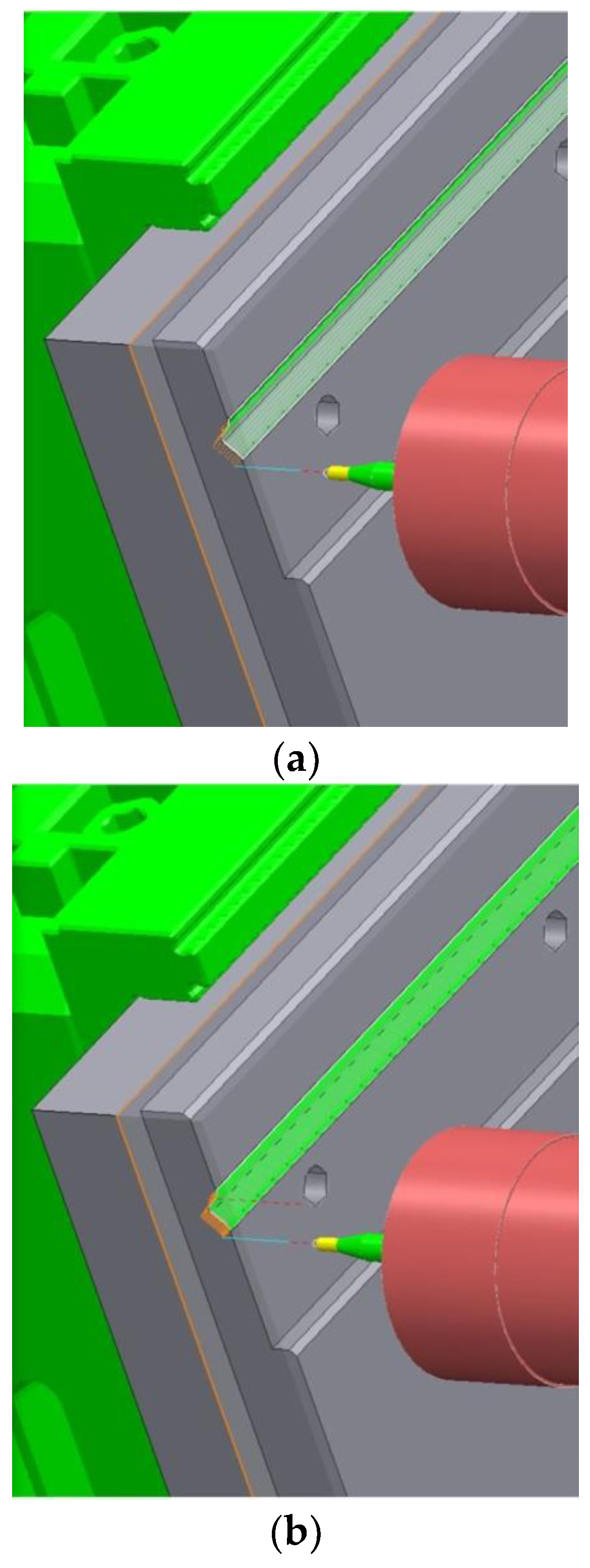
The “Raster” trajectory is used for roughing and finishing; the difference is in the assignment of the “processing step” parameter: a larger step (0.4 mm) was assigned for roughing and a smaller one (0.1 mm) for finishing. The final roughing time was 4 min, and the finishing time was 16 min. Figure 14 shows the strategies for roughing and finishing a wedge-shaped groove.
The manufacture of M6 holes required using a centering drill with a diameter of 3.15 mm, DH404050 carbide drill with a diameter of 5 mm, and GTM3-AL DLC M6 three-row thread mill. The trajectory parameters for centering drilling were as follows: 1. Cycle type (Deep drill). 2. Define top by (Hole top). 3. Clearance (5.0 mm). 4. Peck Depth (0.5 mm). 5. Depth (1.0 mm). 6. Tolerance (0.1 mm). 7. Drilling cycle output. The drilling trajectory parameters were as follows: 1. Cycle type (deep drill). 2. Define top by (hole top). 3. Clearance (5.0 mm). 4. Peck Depth (0.5 mm). 5. Depth (25.0 mm). 6. Tolerance (0.1 mm). 7. Drilling cycle output. The thread milling path parameters were the following: 1. Cycle type (thread milling). 2. Define top by (hole top). 3. Clearance (5.0 mm). 4. Turns (16.0 mm). 5. Depth (15.0 mm). 6. Pitch (1.0 mm). 7. Tolerance (0.1 mm). 8. Direction (Climb). 9. Thickness (−0.56 mm). The total time for making holes was 23 min. Figure 15 shows the trajectory parameters for each operation.
The working edge after the first setup at the first transition has an allowance designed for precise positioning at the second setup (technological allowance) in the form of a step (Figure 16).
The principle of processing on the second setup is the same as the first, with a small time difference: the total roughing time was 96 min, and the finishing time was 52 min.
After the second setup, the residual allowance on the working edge of the punch is minimal, roughly 0.2 mm for semi-finishing milling on the third setup. The design of the part after the second setup is shown in Figure 17.
At the third setup, the workpiece is refined along the working surfaces of the punch. The subsequent transitions within the integrated processing, “Surface Hardening by HEH HFC” and “Grinding and Sparking-Out”, are carried out without re-setting up the workpiece. The results of previous studies have shown [14,29] that when implementing hybrid processing of “rigid parts” (the ratio between the total thickness of the part (the wall of the part) and the depth of the hardened layer ≥ 7) allows pre-machining of surfaces to the size specified in the drawing. The allowance for the finishing grinding and sparking-out that occurs after heat treatment is about 7–10 µm. Given this, the refinement of these surfaces on this setup was carried out without an allowance for subsequent transitions, i.e., an allowance for final processing zmin = 0. The time of roughing and finishing milling at the third setup was 25 min.

3.2. Surface Hardening by High-Energy Heating with High-Frequency Currents

Since surface hardening is carried out immediately after finishing milling without additional re-setting of the punch, a constant gap (δ = 0.1–0.2 mm) is provided between the inductor and the workpiece, which is a necessary condition for the implementation of high-energy heating by high-frequency currents. As previously performed calculations [8,12] showed, for these conditions of hybrid punch processing, due to the absence of a gap between mechanical operations and surface heat treatment, the technological hardening depth at the “Surface hardening by HEH HFC” transition should be AT = 0.52+0.28 mm [8].
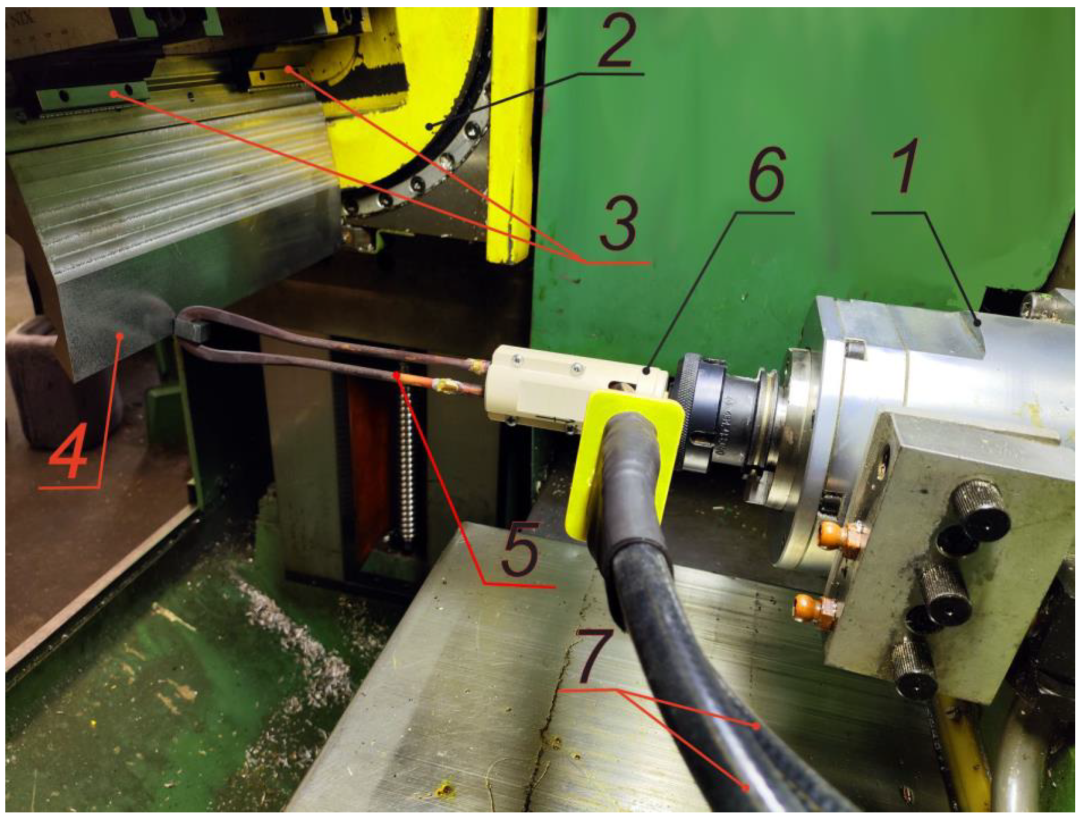
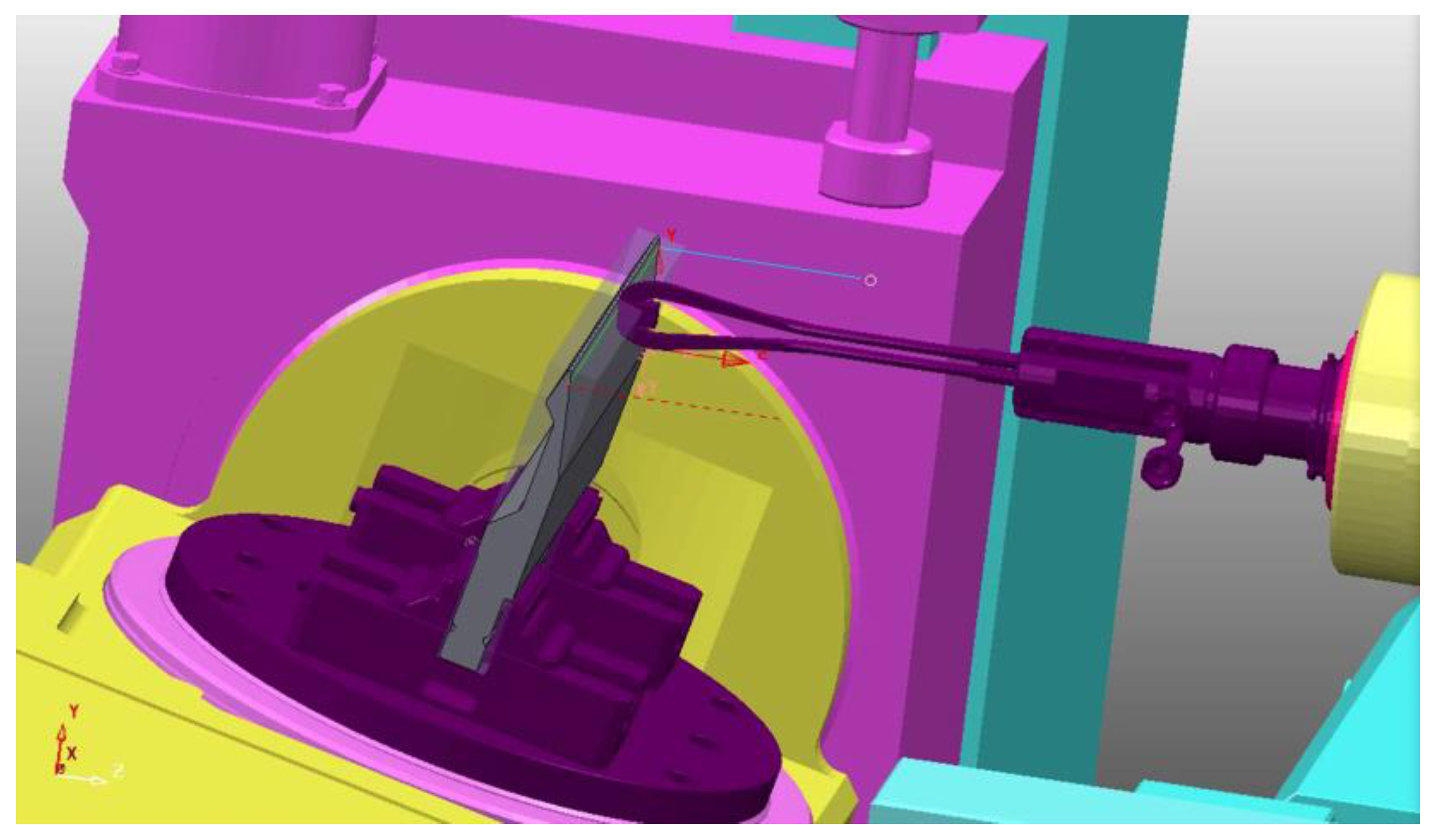
The process of surface hardening employed a loop-type inductor equipped with N87 ferrite (Figure 18) [8]. As a special tool for fixing the inductor, a transition fixture was designed and manufactured to be installed in a tool chuck with a collet clamp. Glass-filled plastic of the ZX-324 GF30 PEEK brand was used as the insulating material of the transition fixture since it also provided the required strength and rigidity. Intensive water circulation cooling provided by the CH-2F chiller was used to regulate the required temperature regime of the inductor and the SVCh-10 ultra-high-frequency thyristor generator.
A command that enables turning on a pre-configured high-frequency generator SVCh-10 with the command “M36” from the machine stand was added to the CNC system, during the surface hardening process implementation on the MS032 5-axis milling machine. The spindle axis was represented as an additional axis with the address “B” in order to calculate the inductor’s position in space. The positioning of this axis in space was carried out in the range from −90 to 90 degrees. The positioning restriction removes the chance of tool failure by preventing the inductor’s flexible busbar from winding. Notably, this range of rotation angle along the B axis is sufficient to accept any desired position of the inductor.
The next crucial step in the production preparation process was to write a special post-processor that enables the use of hybrid equipment functionality and to create a program that controls all the requirements for the HEH HFC surface hardening process. The following stages of the work were carried out to solve the given task.
  • At the first stage, all machine components were modeled with maximum accuracy of dimensional parameters in the COMPASS 3D CAD system, followed by the preparation of unit models for import into the PowerMILL CAM system in the “.stl” format.
  • At the second stage, the control file of the machine kinematics was assembled, which enabled interaction with machine models and a post-processor when creating a control program, reproducing all the working movements of the process equipment inside the CAM system. In this case, the hybrid machine has one more axis in the software since the spindle has an active positioning capability and has the index “B”, and the rotary table axes have indexes “A” and “C”, respectively.
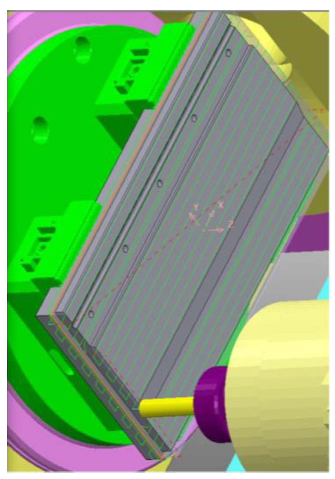
  • The third, most time-consuming stage was the writing of a post-processor that includes all interdependent commands to ensure the correct operation of the system. This process was accompanied by the parallel writing of a control program to determine the correctness of the post-processor. The way the variables interact in the system is as follows: the program text contains the “code” for activating the spindle positioning in the initial position “G01 B0 F5” when choosing an inductor tool with a unique number. In this case, the address-dependent variable “B” refers to a position in the program achieved by turning the spindle axis in the desired direction at a fixed speed set as revolutions per minute through the parameter “F.” When positioning the spindle to the home position, the program uses the function G01—linear interpolation. Next, the positioning block is turned on to the first initial point at a safe height from the part, taking into account the length of the tool “G00 X0 Y0 Z161 A15 C0”. When positioning to the starting point at a safe height, the program uses the function G00—rapid positioning. This is followed by a block with the activation code of the high-frequency generator and the start of its cooling system, “M36.” Next, the program executes relative motions of the tool and the workpiece with the constant contour speed required for hardening. The program operates based on standard algorithms, but it observes the required distance of 0.15 mm between the workpiece surface and the working area of the inductor. Table 5 and Figure 19 show the kinematic structure and general view of the axis-tracking program. Upon completion of the transition “Surface Hardening by HEH HFC”, the power supply system of the high-frequency generator is switched off by the software.
The calculation results of the HMS specifications show that in order to ensure a level of shaping performance comparable to mechanical operations, it is necessary to process by HEH HFC at speeds of about vs. ∈ [1; 100] mm/s. The replacement of the elements of the DC motor control units, which control the drives along the linear and circular axes X, Y, Z, A, and C, with modern ELL 12030 digital thyristor converters, allowed to expand the control range of working feeds. The range of specific power of the source qS (h, VS) required to perform processing by HEH HFC was obtained through the analysis of field experiments as well as data from modeling thermal fields and structural-phase transformations in steel under high-energy heating with high-frequency currents. The resulting value is qS ∈ [1; 4.0] 108 W/m2.
In order to find efficient modes of surface hardening within the framework of using hybrid processing, the following functional dependencies were established:
  • The dependency between the hardening depth and the processing technological parameters for this steel grade (Figure 20a):
h ( q S , V S ) = a + b V S + c q S + d V S 2 + e q S 2 + f V S q S + g V S 3 + h q S 3 + i V S q S 2 + j V S 2 q S ,
where for the steel U8A, the coefficients are the following: a = 1.122425, b = −25.210979, c = 3.673506·10−9, d = 281.263627, e = 8.690586·10−18, f = −8.175952·10−8, g = −1471.413565, h = 1.428863·10−27, i = −9.270236·10−17, j = 6.005372·10−7.
2.
The dependency of the relative magnitude of the transition zone of the hardened layer Ψ on the power qs and the velocity Vs of the energy source at HEH HFC (Figure 20b):
Ψ ( q S , V S ) = k + l V S + m q S + n V S 2 + o q S 2 + p V S q S + r V S 3 + s q S 3 + t V S q S 2 + u V S 2 q S ,
where for the steel U8A, the coefficients are the following: k = 0.799, l = 7.5618969·10−7, m = 5.0855607·10−17, n = −9.2730023·10−6, o = −1.238302·10−25, p = −5.3673819·10−16, r = −371.486996, s = −2.1496·10−26, t = 8.3897156·10−27, u = 3.2127365·10−15.
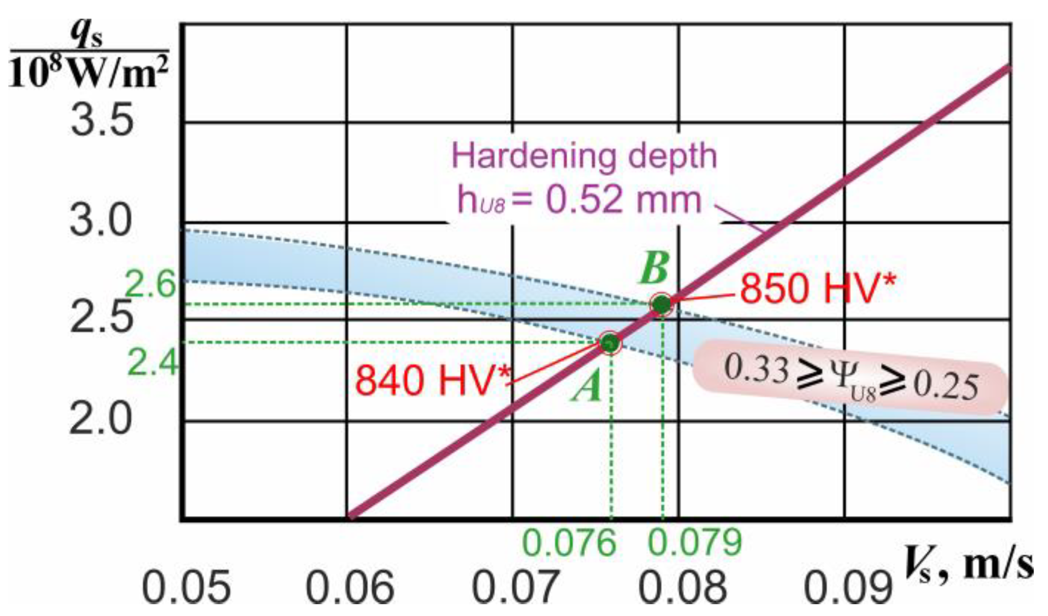
The amount and type of residual stress distribution across the hardened material’s depth must be considered for parts operating under contact fatigue loading. Accordingly, field experiments and numerical modeling results have demonstrated that finding the rational modes of HEH HFC requires solving a system of equations { h U 8 ( q S , V S ) ; Ψ U 8 ( q S , V S ) . for the given values of the hardening depth and the relative dimensions of the transition zone (where ΨU8 is the ratio of the transition zone’s dimensions to the hardened layer’s depth). The graphical solution to this problem is presented in Figure 21.
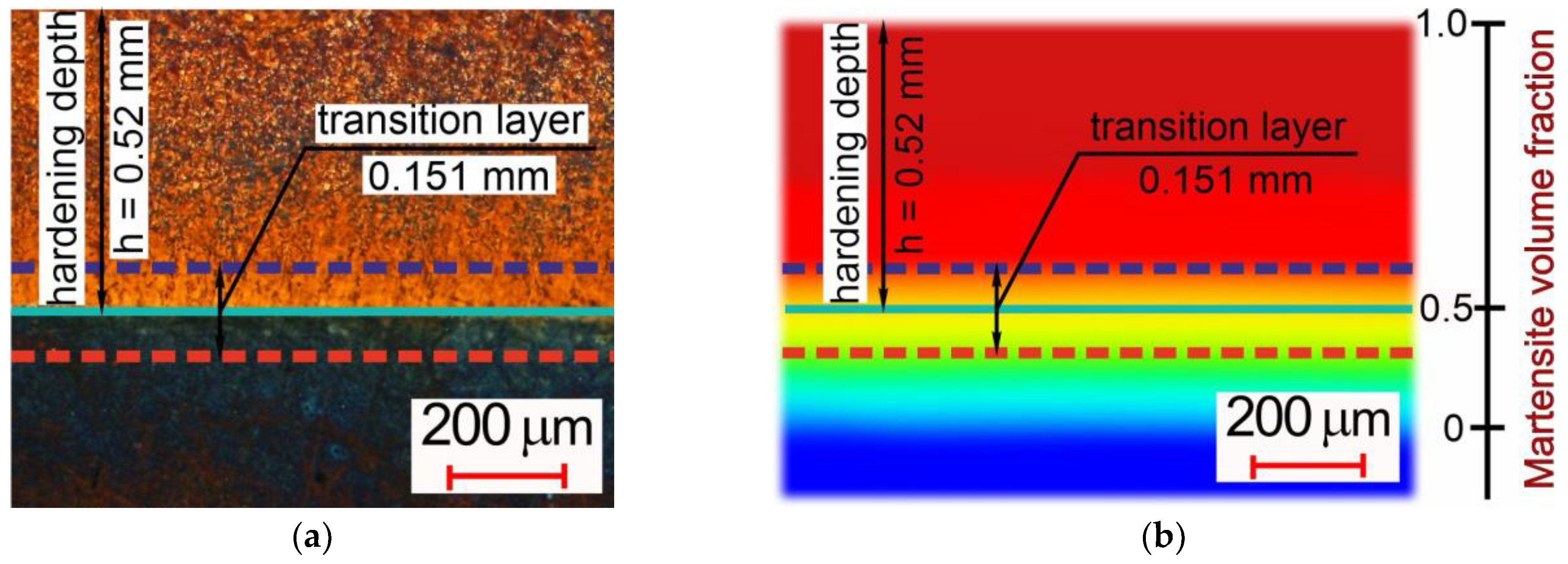
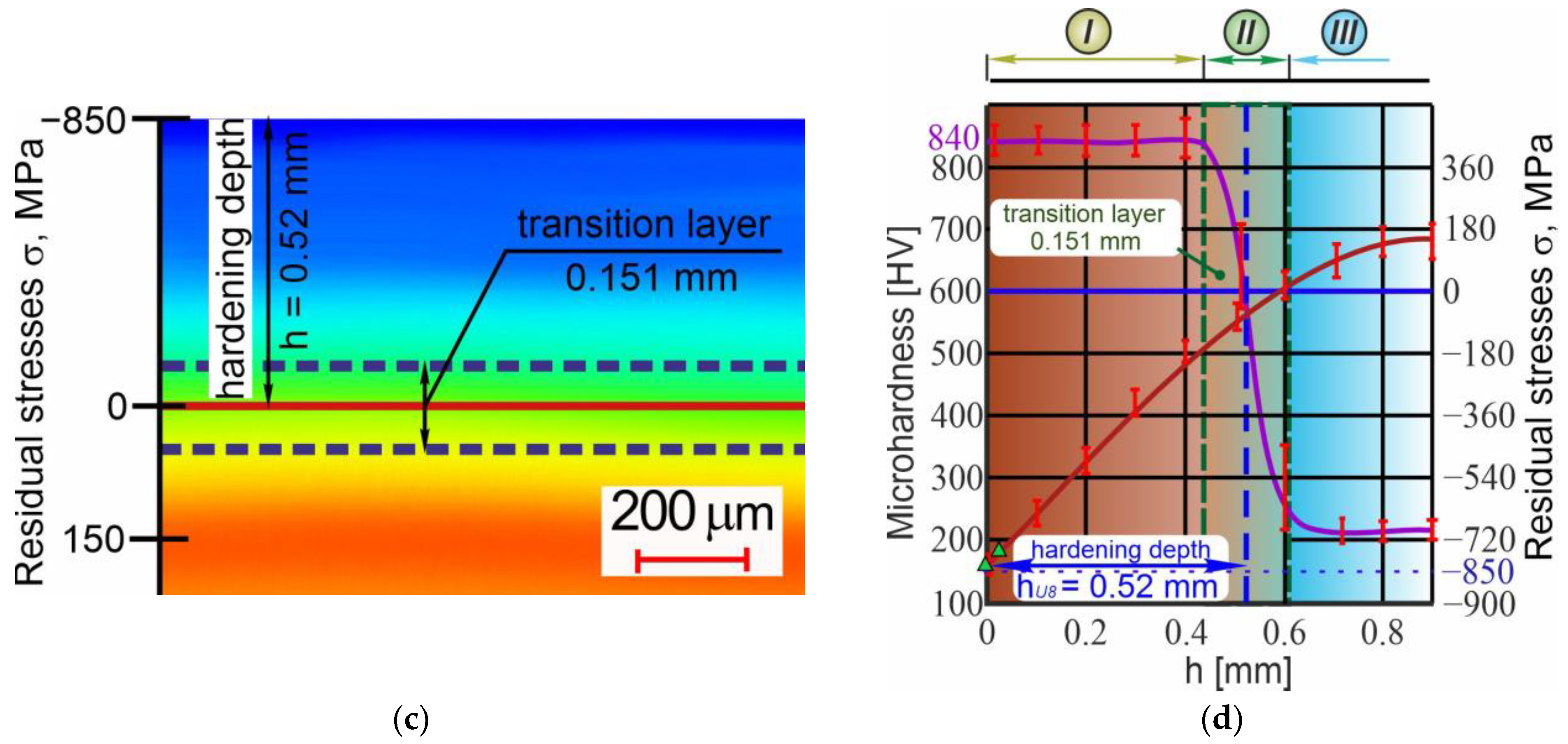
The resulting range of operating parameters from point A [2.4·108 W/m2; 76 mm/s] to point B [2.6·108 W/m2; 79 mm/s] guarantees not only the required depth (hU8 = 0.52 mm) and the value of surface hardness (800–900 HV) of the hardened layer (Figure 1), but also the rational nature of the redistribution of residual stresses in the surface-hardened material of the product. Figure 22 shows the experimental results for the option of hardening the working surfaces of the punch (Figure 1) in the following modes: [qS = 2.5·108 W/m2; vs. = 78 mm/s]. According to the results of optical microscopy (Figure 22a) and the data from the mathematical simulation of structural-phase transformations (Figure 22b), the depth of the hardened layer is roughly h = 0.52 mm. The dimension of the transition layer is 0.151 mm, which, at these values, yields Ψ = 0.29. Accordingly, the relative magnitude of the transition zone of the hardened layer falls within the required range of variation Ψ ∈ [0.25; 0.33]. The rationality of the assigned operating parameters at the HEH HFC transition is confirmed by the data from modeling the stress–strain state (Figure 22c) and the results of field experiments to determine residual stresses (Figure 22d). Thus, the maximum level of axial residual stresses is located precisely on the surface of the product and reaches a value of about 850 MPa. The region with the maximum level of tensile residual stresses is located at a depth of about ~0.9 mm, far beyond the hardened layer, in the zone of the material in which no structural or phase transformations have occurred. The level of surface microhardness of the hardened layer reaches values of 840 HV, which is included in the required range of microhardness changes indicated in the technical requirements for the manufacture of the punch.
Owing to the disparity between the initial structure’s and martensite’s specific volumes, surface hardening caused an 8 µm increase in size on each side.
The total time for the transition “Surface Hardening by HEH HFC” was 4 min, taking into account the connection and disconnection of the flexible busbar from the generator to the inductor.

3.3. Finishing Mechanical Treatment: Grinding

Using an adjustable boring head, a high-speed spindle is installed into the machine’s main spindle during the third transition of hybrid machining in automatic mode. The dimensions of the processed working part of the punch and the specifications of the Planet 600 M2040 system conditioned the finishing grinding of hardened steel (Ra = 0.4 µm) and the subsequent sparking-out. The shaping was performed with the cylindrical grinding heads made of white electrocorundum: AW 13 × 25 × 6 − 40 25A F80 K6 V A 35 m/s (Figure 23).
The grinding modes are the following: cutting speed V = 35 m/s (rotation speed of the grinding head n = 51,420 min−1); cutting depth t = 0.005 mm; maximum grinding width b = 10 mm; feed F = 2.7 m/min (2700 mm/min). The effective power of grinding at a cutting speed of 35 m/s according to [61] is equal to the following equation:
N e = C N F r t x b z ,
where the coefficient CN = 0.7; exponents r = 0.7, x = 0.5 and b = 0.5. Accordingly, Ne = 314 W, which is less than the maximum permissible value for Planet 600 M2040 (400 W).
The setting of the required cutting speed is previously carried out by joint control of the pneumatic drive system of the high-speed spindle with the Planet 600 M2040 Jig Grinding Spindle air turbine.
Based on the fact that the grain size of the grinding head is F80, the average radius of rounding of the abrasive grains is 16 ± 5 µm, respectively [14,29,62]. Consequently, the allowance (8 µm) and the cutting depth (5 µm) that occur after heat treatment are significantly less than the average radius of the abrasive grain, which minimizes the possibility of mechanical removal of metal and determines its plastic deformation during processing with the formation of a work-hardened surface layer [14,29,63]. Furthermore, the research conducted indicates that the proposed integration principle, which permits the processing of parts on a single technological basis, can enhance the quality of the products’ surface layer by maintaining the hardness value, the level, and the nature of the compressive residual stresses’ distribution at the transition “Surface Hardening by HEH HFC”.
The grinding of the working surface of the punch is carried out in two longitudinal passes of the grinding head, removing 5 µm on the first pass and 3 µm on the second. The processing is carried out in one setup, which in turn eliminates the changeover time compared to classic grinding. Figure 24 shows the processing scheme of one of the working surfaces of the punch.
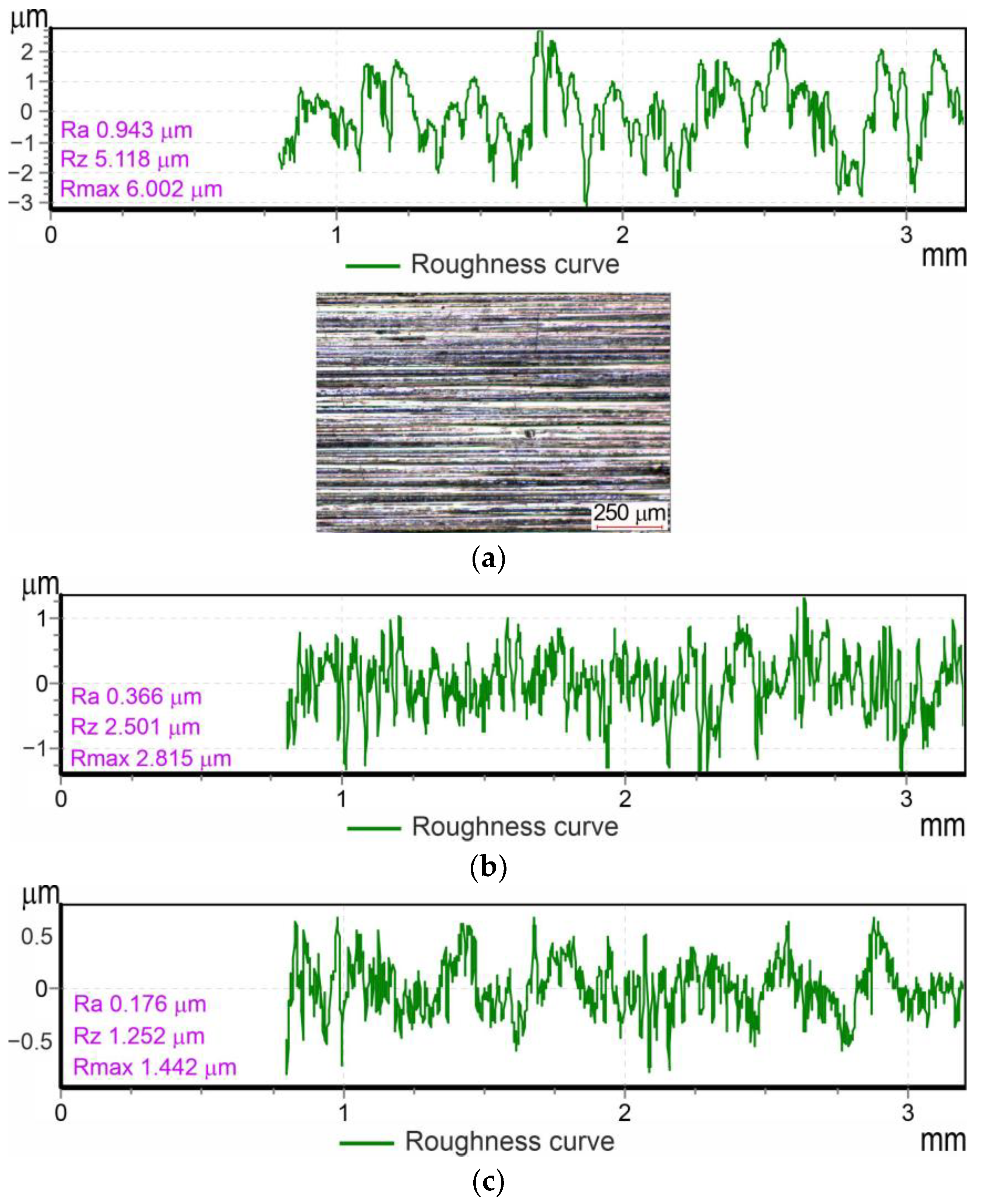
Figure 25 shows the evolution of surface roughness changes at the “Grinding” transition. Experimentally, after the first and second passes, the following roughness indicators were obtained on the treated surface: Rapass 1 = 0.976 ± 0.096 µm (Figure 25a); Rapass 2 = 0.386 ± 0.055 µm (Figure 25b). Subsequent sparking-out contributes to an increase in surface microhardness and the reduction and leveling of roughness. Thus, after 20 s of sparking-out the working surfaces of the punch, the achieved microhardness values were about 910 HV, and surface roughness was Ra = 0.197 ± 0.021 µm (Figure 25c), while the level of useful compressive stresses in the surface layer increased to σ = 900 MPa. Analyzing the data obtained, it can be found that each subsequent pass during finishing grinding allows to significantly reduce surface roughness, by practically 2.53 times. At the same time, quenching for only 20 s allowed to reduce surface roughness by about 1.96 times.
The functional dependence of the change in the surface roughness parameter Ra on the time of sparking-out τsparking-out was found during the statistical processing of the experimental data. This can be expressed mathematically as follows:
R a ( τ sparking - out ) = R a i n i t i a l 1 + τ sparking - out / 21.81 ,
where Rainitial is the initial surface roughness value, µm (reached before the sparking-out process), τsparking-out is the sparking-out time, s.
Notably, not a single punch was rejected during the grinding out of the entire batch (150 pieces). However, according to the company GLK-Industrial Technologies, which manufactures this type of product using standard technology, about 7% of manufactured parts are subject to rejection due to the presence of burns and microcracks on the surface formed during the grinding.
The total time for the transition to “Grinding”, taking into account the connection and disconnection of flexible hoses from the pneumatic system to the high-speed spindle, was 6 min.
Thus, summing up all the time intervals for each of the transitions, the spent time T = 276 min. This is the total time for manufacturing a punch on a hybrid CNC metalworking machine. The classical manufacturing technology requires a large number of transitions from one piece of technological equipment to another; even without taking into account the transportation time, the total processing time is about 525 min, which is 1.9 times more than the proposed technology.

4. Conclusions

  • The results of structural and kinematic analysis prove that all the transitions in integral machining require a similar set of working machine movements and a similar number of their adjustable parameters. It was found that the layout of the machine system of MS032.06 five-coordinate multi-purpose machining center is preferable for embedding an additional energy source into it, such as SVCh-10, an ultra-high-frequency thyristor generator.
  • Based on the results of modeling the operational characteristics of a hybrid machine tool complex, the main drive of the machine was upgraded by replacing the existing electric drive with an asynchronous electric motor with frequency control. To ensure full-fledged 5-axis high-performance machining, as well as the possibility of integrating the SVCh-10 generator control system into the CNC machine, the standard Fanuc 6M model B CNC system was replaced with NC-400 (UEFI) CNC. The replacement of elements of DC motor control units, which control linear and circular axis drives X, Y, Z, A, and C, with modern ELL 12030 digital thyristor converters, allowed for expanding the control range of working feeds and achieving high-energy heating with high-frequency currents with the required performance.
  • The range of HEH HFC modes and the rationality of the residual stresses’ redistribution in the surface-hardened material of the product are determined based on the findings of field experiments and data from finite element modeling of thermal fields, structural-phase transformations, and stress–strain states in steel under high-energy heating by high-frequency currents.
  • Theoretical research revealed that grinding should be used at the last transition to ensure the required level of product-processing quality. The implementation of grinding on upgraded equipment became possible due to the use of a high-speed spindle system with an air turbine. The conducted research demonstrated that the introduction of the proposed integration principle, which ensures the processing of parts on a single technological basis, can significantly reduce the allowance for finish grinding. This ensures an increase in the quality of the surface layer of the products. In particular, during the implementation of grinding and sparking-out, the microhardness indicators achieved in the HEH HFC process and the level of compressive stresses in the surface layer of the material increase by 6–8%.
  • The research team has developed a sample of hybrid metalworking equipment with numerical control and has written a unique post-processor for it, which allows for implementing all the functions of this machine tool system and the combined processing technology as a whole. They have also designed and manufactured special equipment and tools to ensure all the necessary requirements for the process of surface hardening by HEH HFC. The completed works and the approval of integrated processing technology in real conditions, when compared with traditional methods of designing the process of manufacturing parts, demonstrated a significant (1.9 times) increase in processing performance. Furthermore, the possibility of defects occurring during finishing grinding was completely eliminated, while the time required for auxiliary, preparatory, and final operations was reduced. Finally, the buffer storage was also reduced.

Author Contributions

Conceptualization, V.S.; methodology, V.S. and V.I.; validation, V.S., A.C., N.M., N.V. and K.T.; formal analysis, V.S. and V.I.; investigation, V.S., A.C., N.V. and K.T.; data curation, V.S., A.C., N.V. and K.T.; writing—original draft preparation, V.S. and A.C.; writing—review and editing, V.S. and V.I.; supervision, V.S.; project administration, V.S.; funding acquisition, V.S., N.V. and K.T. All authors have read and agreed to the published version of the manuscript.

Funding

This research was funded by Russian Science Foundation project N 23-29-00945, https://rscf.ru/en/project/23-29-00945/ (accessed on 17 August 2024).

Data Availability Statement

The data presented in this study are available from the corresponding authors upon reasonable request.

Acknowledgments

The research was carried out at the equipment of the Engineering Center “Design and Production of High-Tech Equipment”.

Conflicts of Interest

The authors declare no conflicts of interest.

References

  1. Liao, Z.; Schoop, J.M.; Saelzer, J.; Bergmann, B.; Priarone, P.C.; Splettstößer, A.; Bedekar, V.M.; Zanger, F.; Kaynak, Y. Review of current best-practices in machinability evaluation and understanding for improving machining performance. CIRP J. Manuf. Sci. Technol. 2024, 50, 151–184. [Google Scholar] [CrossRef]
  2. Holmberg, J.; Berglund, J.; Wretland, A.; Klason, A.; Persson, R. Milling or grinding for manufacturing of an Alloy 718 gas turbine component?—A comparison of surface integrity and productivity. Procedia CIRP 2024, 123, 7–12. [Google Scholar] [CrossRef]
  3. Machado, A.R.; da Silva, L.R.R.; Pimenov, D.Y.; de Souza, F.C.R.; Kuntoğlu, M.; de Paiva, R.L. Comprehensive review of advanced methods for improving the parameters of machining steels. J. Manuf. Process. 2024, 125, 111–142. [Google Scholar] [CrossRef]
  4. Archenti, A.; Gao, W.; Donmez, A.; Savio, E.; Irino, N. Integrated metrology for advanced manufacturing. CIRP Ann. 2024, 73, 639–665. [Google Scholar] [CrossRef]
  5. Axinte, D. Portable robotised machines tools (RoboMach), for in-situ inspection and (re)manufacture: Research challenges and opportunities. Int. J. Mach. Tools Manuf. 2024, 195 Pt A, 104115. [Google Scholar] [CrossRef]
  6. Zhang, Y.; Du, G.; Li, H.; Yang, Y.; Zhang, H.; Xu, X.; Gong, Y. Multi-objective optimization of machining parameters based on an improved Hopfield neural network for STEP-NC manufacturing. J. Manuf. Syst. 2024, 74, 222–232. [Google Scholar] [CrossRef]
  7. Nguyen, T.-N.-H.; Le, D.-B.; Nguyen, D.-T. Automation for feed motion of flat grinding machine improve accuracy and productivity machine. Mater. Today. Proc. 2023, 81 Pt 2, 427–433. [Google Scholar] [CrossRef]
  8. Skeeba, V.Y.; Vakhrushev, N.V.; Titova, K.A.; Chernikov, A.D. Rationalization of modes of HFC hardening of working surfaces of a plug in the conditions of hybrid processing. Obrab. Met. 2023, 25, 63–86. [Google Scholar] [CrossRef]
  9. Lv, J.; Tang, R.; Jia, S.; Liu, Y. Experimental study on energy consumption of computer numerical control machine tools. J. Clean. Prod. 2016, 112, 3864–3874. [Google Scholar] [CrossRef]
  10. Makarov, V.M. Well integrated technological systems: Prospects and problems of implementation. Repair. Innov. Technol. Mod. 2011, 6, 20–23. [Google Scholar]
  11. Makarov, V.M.; Lukina, S.V. Unique synergy of hybrid machines. Repair. Innov. Technol. Mod. 2016, 8, 18–25. [Google Scholar]
  12. Skeeba, V.Y.; Ivancivsky, V.V. Improving the efficiency of surface thermal hardening of machine parts in conditions of combination of processing technologies, integrated on a single machine tool base. Obrab. Met. 2021, 23, 45–71. [Google Scholar] [CrossRef]
  13. Mitsuishi, M.; Ueda, K.; Kimura, F. Manufacturing Systems and Technologies for the New Frontier; Springer Publ.: London, UK, 2008; p. 556. ISBN 978-1-84800-267-8. [Google Scholar] [CrossRef]
  14. Ivancivsky, V.V.; Skeeba, V.Y. Hybrid Metal Working Equipment. Technological Aspects of Integrating the Operations of Surface Hardening and Abrasive Grinding; NSTU Publ.: Novosibirsk, Russia, 2019; p. 348. ISBN 978-5-7782-3988-3. [Google Scholar]
  15. Lauwers, B.; Klocke, F.; Klink, A.; Tekkaya, A.E.; Neugebauer, R.; Mcintosh, D. Hybrid processes in manufacturing. CIRP Ann. 2014, 63, 561–583. [Google Scholar] [CrossRef]
  16. Moriwaki, T. Multi-functional machine tool. CIRP Ann. 2008, 57, 736–749. [Google Scholar] [CrossRef]
  17. Brecher, C.; Özdemir, D. Integrative Production Technology: Theory and Applications; Springer International Publ.: London, UK, 2017; p. 1100. ISBN 978-3-319-47451-9/978-3-319-47452-6. [Google Scholar] [CrossRef]
  18. Yamazaki, T. Development of A Hybrid Multi-tasking Machine Tool: Integration of Additive Manufacturing Technology with CNC Machining. Procedia CIRP 2016, 42, 81–86. [Google Scholar] [CrossRef]
  19. Kushnarenko, S.V.; Fomichev, A.O.; Astakhov, Y.P.; Bogdanov, K.A.; Perepechkin, A.A.; Belov, I.I. New Science Intensive Technologies for Electrophysical and Chemical Treatment of Aerospace Parts. Proc. High. Educ. Institutions. Machine Build. 2019, 11, 46–54. [Google Scholar] [CrossRef]
  20. Skeeba, V.Y. Hybrid process equipment: Improving the efficiency of the integrated metalworking machines initial designing. Obrab. Met. Met. Work. Mater. Sci. 2019, 21, 62–83. [Google Scholar] [CrossRef]
  21. Borisov, M.A.; Lobanov, D.V.; Zvorygin, A.S.; Skeeba, V.Y. Adaptation of the CNC system of the machine to the conditions of combined processing. Obrab. Met. 2024, 26, 55–65. [Google Scholar] [CrossRef]
  22. You, K.; Yan, G.; Luo, X.; Gilchrist, M.D.; Fang, F. Advances in laser assisted machining of hard and brittle materials. J. Manuf. Process. 2020, 58, 677–692. [Google Scholar] [CrossRef]
  23. Sun, S.; Brandt, M.; Dargusch, M.S. Thermally enhanced machining of hard-to-machine materials—A review. Int. J. Mach. Tools Manuf. 2010, 50, 663–680. [Google Scholar] [CrossRef]
  24. Kim, S.-G.; Lee, C.-M.; Kim, D.-H. Plasma-assisted machining characteristics of wire arc additive manufactured stainless steel with different deposition directions. J. Mater. Res. Technol. 2021, 15, 3016–3027. [Google Scholar] [CrossRef]
  25. Lee, Y.-H.; Lee, C.-M. A Study on Optimal Machining Conditions and Energy Efficiency in Plasma Assisted Machining of Ti-6Al-4V. Materials 2019, 12, 2590. [Google Scholar] [CrossRef]
  26. Liao, Z.; Xu, D.; Luna, G.G.; Axinte, D.; Augustinavicius, G.; Sarasua, J.A.; Wretland, A. Influence of surface integrity induced by multiple machining processes upon the fatigue performance of a nickel based superalloy. J. Mater. Process. Technol. 2021, 298, 117313. [Google Scholar] [CrossRef]
  27. Wu, C.; Zhang, T.; Guo, W.; Meng, X.; Ding, Z.; Liang, S.Y. Laser-assisted grinding of silicon nitride ceramics: Micro-groove preparation and removal mechanism. Ceram. Int. 2022, 48, 32366–32379. [Google Scholar] [CrossRef]
  28. Rao, T.B. Reliability analysis of the cutting tool in plasma-assisted turning and prediction of machining characteristics. Aust. J. Mech. Eng. 2020, 20, 1020–1034. [Google Scholar] [CrossRef]
  29. Skeeba, V.Y.; Ivantcivsky, V.V. Hybrid Metal Working Equipment: Improving the Effectiveness of the Details Processing under the Integration of Surface Quenching and Abrasive Grinding; NSTU Publ.: Novosibirsk, Russia, 2018; p. 312. ISBN 978-5-7782-3690-5. [Google Scholar]
  30. Nagesh, S.; Law, M. Machine tool design with preferentially asymmetrical structures to improve dynamics and productivity. Procedia CIRP 2019, 79, 592–595. [Google Scholar] [CrossRef]
  31. Costa, S.; Silva, F.J.G.; Campilho, R.D.S.G.; Pereira, T. Guidelines for Machine Tool Sensing and Smart Manufacturing Integration. Procedia Manuf. 2020, 51, 251–257. [Google Scholar] [CrossRef]
  32. Olsson, M.; Akujärvi, V.; Ståhl, J.-E.; Bushlya, V. Cryogenic and hybrid induction-assisted machining strategies as alternatives for conventional machining of refractory tungsten and niobium. Int. J. Refract. Met. Hard Mater. 2021, 97, 105520. [Google Scholar] [CrossRef]
  33. Baek, J.-T.; Woo, W.-S.; Lee, C.-M. A study on the machining characteristics of induction and laser-induction assisted machining of AISI 1045 steel and Inconel 718. J. Manuf. Process. 2018, 34, 513–522. [Google Scholar] [CrossRef]
  34. Liu, J.; Li, Y.; Chen, Y.; Zhou, Y.; Wang, S.; Yuan, Z.; Jin, Z.; Liu, X. A review of low-temperature plasma-assisted machining: From mechanism to application. Front. Mech. Eng. 2023, 18, 18. [Google Scholar] [CrossRef]
  35. Kim, E.-J.; Lee, C.-M. Experimental study on power consumption of laser and induction assisted machining with Inconel 718. J. Manuf. Process. 2020, 59, 411–420. [Google Scholar] [CrossRef]
  36. Ma, Z.; Wang, Z.; Wang, X.; Yu, T. Effects of laser-assisted grinding on surface integrity of zirconia ceramic. Ceram. Int. 2020, 46, 921–929. [Google Scholar] [CrossRef]
  37. Xu, M.; Wei, R.; Li, C.; Ko, T.J. High-frequency electrical discharge assisted milling of Inconel 718 under copper-beryllium bundle electrodes. J. Manuf. Process. 2023, 85, 1116–1132. [Google Scholar] [CrossRef]
  38. Kim, J.; Zani, L.; Abdul-Kadir, A.; Roy, A.; Baxevanakis, K.P.; Jones, L.C.R.; Silberschmidt, V.V. Hybrid-hybrid turning of micro-SiCp/AA2124 composites: A comparative study of laser-and-ultrasonic vibration-assisted machining. J. Manuf. Process. 2023, 86, 109–125. [Google Scholar] [CrossRef]
  39. Skeeba, V.Y.; Ivancivsky, V.V.; Martyushev, N.V. Peculiarities of High-Energy Induction Heating during Surface Hardening in Hybrid Processing Conditions. Metals 2021, 11, 1354. [Google Scholar] [CrossRef]
  40. Gao, K.; Qin, X. Effect of feed path on the spot continual induction hardening for different curved surfaces of AISI 1045 steel. Int. J. Heat. Mass. Transf. 2020, 115, 104632. [Google Scholar] [CrossRef]
  41. Zykova, A.; Zadkov, D.; Kuzkin, A. Influence of W Addition on Microstructure and Mechanical Properties of Al-12%Si Alloys. Materials 2019, 12, 981. [Google Scholar] [CrossRef]
  42. Asadzadeh, M.Z.; Raninger, P.; Prevedel, P.; Ecker, W.; Mücke, M. Hybrid modeling of induction hardening processes. Appl. Eng. Sci. 2021, 5, 100030. [Google Scholar] [CrossRef]
  43. Isametova, M.E.; Karlina, Y.I.; Kononenko, R.V.; Absadykov, B.N. Thermal Pulse Processing of Blanks of Small-Sized Parts Made of Beryllium Bronze and 29 NK Alloy. Materials 2022, 15, 6682. [Google Scholar] [CrossRef]
  44. Kim, J.-H.; Kim, E.-J.; Lee, C.-M. A study on the heat affected zone and machining characteristics of difficult-to-cut materials in laser and induction assisted machining. J. Manuf. Process. 2020, 57, 499–508. [Google Scholar] [CrossRef]
  45. Rezanov, V.A.; Kukartsev, V.V.; Tynchenko, V.S.; Kukartsev, V.A.; Grinek, A.V.; Lyosin, A.V.; Karlina, A.I. Study of Melting Methods by Electric Resistance Welding of Rails. Metals 2022, 12, 2135. [Google Scholar] [CrossRef]
  46. Ha, J.-H.; Lee, C.-M. A Study on the Thermal Effect by Multi Heat Sources and Machining Characteristics of Laser and Induction Assisted Milling. Materials 2019, 12, 1032. [Google Scholar] [CrossRef]
  47. Akzharkyn, I.; Yelemessov, K.; Baskanbayeva, D.; Konyukhov, V.Y.; Oparina, T.A. Strengthening Polymer Concrete with Carbon and Basalt Fibres. Appl. Sci. 2024, 14, 7567. [Google Scholar] [CrossRef]
  48. Yelemessov, K.; Baskanbayeva, D.; Gozbenko, V.E.; Karlina, A.I. Change in the Properties of Rail Steels during Operation and Reutilization of Rails. Metals 2023, 13, 1043. [Google Scholar] [CrossRef]
  49. Kim, E.J.; Lee, C.M. A Study on the Optimal Machining Parameters of the Induction Assisted Milling with Inconel 718. Materials 2019, 12, 233. [Google Scholar] [CrossRef]
  50. Skeeba, V.Y.; Pushnin, V.N.; Erokhin, I.A.; Kornev, D.Y. Analysis of the stress-strain state of the material under high-energy heating by high frequency currents. Obrab. Met. 2014, 3, 90–102. [Google Scholar]
  51. Efremenkov, E.A.; Grechneva, M.V.; Olisov, A.V.; Ens, A.D. Research on the Possibility of Lowering the Manufacturing Accuracy of Cycloid Transmission Wheels with Intermediate Rolling Elements and a Free Cage. Appl. Sci. 2022, 12, 5. [Google Scholar] [CrossRef]
  52. Ivakhnenko, A.G.; Kuts, V.V.; Erenkov, O.Y.; Ivakhnenko, E.O.; Oleinik, A.V. Effectiveness of structural–parametric synthesis of metal-cutting systems. Russ. Eng. Res. 2017, 37, 901–905. [Google Scholar] [CrossRef]
  53. Nakaminami, M.; Tokuma, T.; Moriwaki, M.; Nakamoto, K. Optimal Structure Design Methodology for Compound Multiaxis Machine Tools –I- Analysis of Requirements and Specifications. Int. J. Autom. Technol. 2007, 1, 78–86. [Google Scholar] [CrossRef]
  54. Nakaminami, M.; Tokuma, T.; Matsumoto, K.; Sakashita, S.; Moriwaki, T.; Nakamoto, K. Optimal Structure Design Methodology for Compound Multiaxis Machine Tools-II-Investigation of Basic Structure. Int. J. Autom. Technol. 2007, 1, 87–93. [Google Scholar] [CrossRef]
  55. Balakshin, B.S. Fundamentals of Mechanical Engineering Technology; Mashinostroenie Publ.: Moscow, Russia, 1969; p. 560. [Google Scholar]
  56. Ivashchenko, I.A. Technological Dimensional Calculations and Methods of their Automation; Mashinostroenie Publ.: Moscow, Russia, 1975; p. 222. [Google Scholar]
  57. Vander Voort, G.F. ASM Handbook. Vol. 9. Metallography and Microstructures; ASM International Publ.: Cleveland, OH, USA, 2004; p. 1184. ISBN 978-0-87170-706-2. [Google Scholar]
  58. Totten, G.E.; Howes, M.; Inoue, T. Handbook of Residual Stress and Deformation of Steel; ASM International: Cleveland, OH, USA, 2002; p. 499. ISBN 978-0-87170-729-1. [Google Scholar]
  59. Sharpe, W.N. Springer Handbook of Experimental Solid Mechanics; Springer Science and Business Media: New York, NY, USA, 2008; p. 1098. ISBN 978-0-387-26883-5. [Google Scholar]
  60. Avraamova, T.M.; Bushuev, V.V.; Gilova, L.Y.; Dosko, S.I.; Eremin, A.V. Metal-Cutting Machines; Mashinostroenie Publ.: Moscow, Russia, 2011; p. 608. ISBN 978-5-94275-594-2. [Google Scholar]
  61. Dal’skii, A.M.; Kosilova, A.G.; Mesheryakov, R.K.; Suslov, A.G. (Eds.) Handbook of a Mechanical Engineer; Mashinostroenie Publ.: Moscow, Russia, 2003; p. 912. ISBN 5-94275-014-9. [Google Scholar]
  62. Loskutov, V.V. Grinding of Metals; Mashinostroenie Publ.: Moscow, Russia, 1970; p. 264. [Google Scholar]
  63. Polevoy, S.N.; Evdokimov, V.D. Strengthening of Engineering Materials; Mashinostroenie Publ.: Moscow, Russia, 1994; p. 496. [Google Scholar]
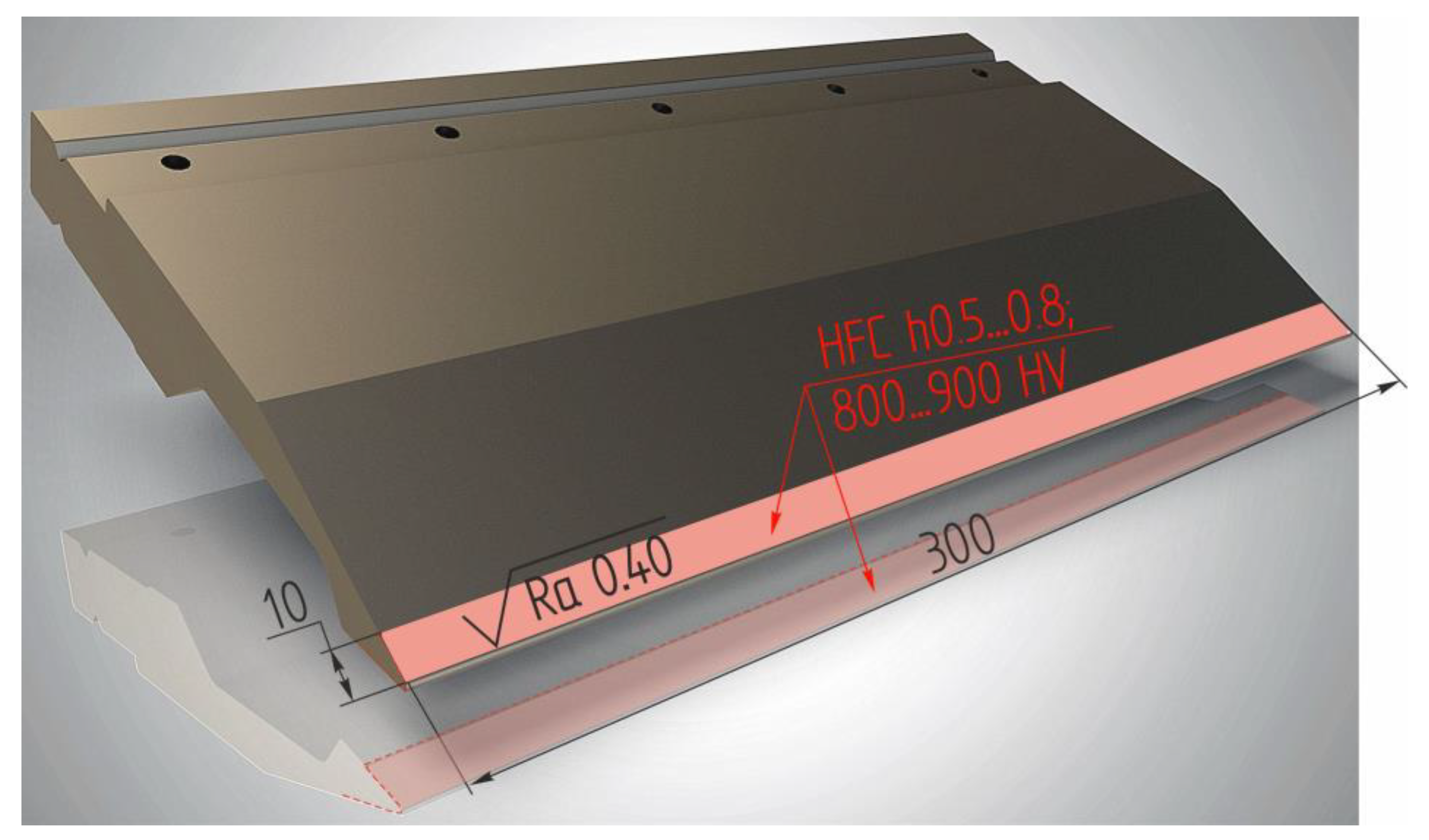
Figure 1. Press brake punch.
Jmmp 08 00200 g001
Figure 2. The scheme of HEH HFC processing.
Jmmp 08 00200 g002
Figure 3. Finite element model of the HEH HFC process.
Jmmp 08 00200 g003
Figure 4. Depth distribution of current density in a two-layer medium.
Jmmp 08 00200 g004
Figure 5. Block schematic diagram of the hybrid metalworking machine.
Jmmp 08 00200 g005
Figure 6. Distribution pattern of operational characteristics of the hybrid machine tool complex: n—spindle speed, min−1; M—spindle torque, Nm; Ne—effective spindle power, kW.
Jmmp 08 00200 g006
Figure 7. Main drive of the metalworking machine model MS032.06.
Jmmp 08 00200 g007
Figure 8. Hybrid metalworking machine.
Jmmp 08 00200 g008
Figure 9. Technological equipment: self-centering vice H77-160 and adapter plate assembled with vice.
Jmmp 08 00200 g009
Figure 10. The roughing formation trajectory at the first transition and installation of the part: (a) simulation in the PowerMill CAM system; (b) processing on a metalworking machine.
Jmmp 08 00200 g010
Figure 11. Surface roughness and topography after rough milling.
Jmmp 08 00200 g011
Figure 12. The finishing milling formation trajectory during the first transition and installation of the workpiece.
Jmmp 08 00200 g012
Figure 13. Surface roughness and topography after finishing milling.
Jmmp 08 00200 g013
Figure 14. Milling of a wedge-shaped groove: (a) roughing; (b) finishing.
Jmmp 08 00200 g014
Figure 15. Trajectories for processing a threaded hole M6: (a) centering; (b) drilling; (c) thread milling.
Jmmp 08 00200 g015
Figure 16. Design and 3D model of the workpiece after the first installation.
Jmmp 08 00200 g016
Figure 17. Design and 3D model of the workpiece after the second installation.
Jmmp 08 00200 g017
Figure 18. Processing area under high-energy heating by high-frequency currents: 1—spindle unit; 2—turntable; 3—self-centering vice chuck; 4—workpiece; 5—inductor; 6—mandrel in tool chuck; 7—flexible busbar.
Jmmp 08 00200 g018
Figure 19. Simulation of processing with axis tracking.
Jmmp 08 00200 g019
Figure 20. Functional dependencies h(qS, VS) (a) and Ψ(qS, VS) (b) for U8A steel.
Jmmp 08 00200 g020
Figure 21. Determination of rational modes for HEH HFC hardening steel U8A to a depth of h = 0.52 mm. * The level of microhardness of the surface layer of the part, achieved after the operation “Surface hardening by HEH HFC”.
Jmmp 08 00200 g021
Figure 22. Experimental results: (a) microstructure of U8A after HEH HFC (optical microscopy); (b) the distribution of the volume fraction of the martensite structure by the depth of the hardened layer (numerical modeling data); (c) the distribution of axial residual stresses (numerical modeling data); (d) the distribution of microhardness and residual stresses in the surface layer (a plot of residual stresses obtained experimentally (by mechanical destructive method)); Jmmp 08 00200 i001—residual stresses obtained by X-ray determination.
Jmmp 08 00200 g022aJmmp 08 00200 g022b
Figure 23. Grinding head AW 13 × 25 × 6 − 40 25A F80 K6 V A 35m/s: (a) abrasive head drawing; (b) abrasive head appearance.
Jmmp 08 00200 g023
Figure 24. Grinding head processing.
Jmmp 08 00200 g024
Figure 25. Surface roughness and topography after finishing milling: (a) after the first grinding pass (t = 5 µm); (b) after the second grinding pass (t = 3 µm); (c) after 20 s of sparking-out.
Jmmp 08 00200 g025
Table 1. The chemical compositions of steel U8A.
ElementsCSiMnSPCrNiCu
Weight, (%)0.810.230.190.0170.020.150.190.16
Table 2. Rough milling processing modes.
For Groups P Material (Steel)Cutting Modes
Cutting Speed Vc, m/minFeed fr,
mm/rev
Cutting Depth ap, mm
Recommended80–2200.1–0.41.0–3.0
Accepted80–2200.152
Table 3. Finishing milling processing modes.
For Groups P Material (Steel)Cutting Modes
Cutting Speed Vc, m/minFeed fm,
mm/min
Cutting Depth ap, mm
Recommended1808600.1
Table 4. Processing modes for milling a wedge-shaped groove with a spherical mill.
For Groups P Material (Steel)Cutting Modes
Cutting Speed Vc, m/minFeed fm,
mm/min
Cutting Depth ap, mm
Recommended11012600.4
Table 5. Kinematic parameters for the hardening process using a high-energy heating by high-frequency currents.
OrderParameterDirectionOriginOrientationLimits
IJKXYZUVWMinInitialMax
Table 000
1st Rotary (C)Machine C00−1000 −3600360
2nd Rotary (A)Machine A100000 −910132
1st Linear (Y)Machine Y0−10 −4000200
Head 0010010100
2nd Linear (X)Machine X100 −2200400
3rd Linear (Z)Machine Z001 00630
3rd Rotary (B)Machine B00−1000 −3600360
Disclaimer/Publisher’s Note: The statements, opinions and data contained in all publications are solely those of the individual author(s) and contributor(s) and not of MDPI and/or the editor(s). MDPI and/or the editor(s) disclaim responsibility for any injury to people or property resulting from any ideas, methods, instructions or products referred to in the content.