2. Determination of Chip Compression Ratio
The determination of the chip compression ratio was practically started about 150 years ago at the same time as the beginning of the scientific research on the cutting process in general due to the developments of Time [
19]. Time established the existence of the plastic deformation of the machined material in the conditional shear plane. Although he assumed that all the work of cutting was spent on its plastic deformation, his research was the impetus for the definition of cutting characteristics such as the chip compression ratio. Time’s studies were further developed by many researchers. In particular, these studies were continued by Zworykin. He was the first to apply the energy method of analyzing the cutting process—the method of minimum potential energy [
20]. Based on this method, Zworykin determined the shear angle and, as a consequence, the chip compression ratio. This analysis method was later used by Merchant to characterize the cutting process, in particular, the shear angle of the machined material in the primary cutting zone [
21]. The next significant step in such research is the studies of De Chiffre [
22]. He determined the relationship between the chip compression ratio and the length of the tool rake face contact with the chip. This made it possible to switch from geometric dependencies for determining the main cutting characteristics, in particular, the shear angle and chip compression ratio, to physical dependencies. De Chiffre proposed the dependence of the stress–strain state of the machined material on the chip compression ratio. These dependencies provided the possibility of the theoretical determination of kinetic characteristics for the cutting process.
Known publications on chip compression ratio determination can be divided into publications using the following methods:
- ➢
Experimental methods;
- ➢
Calculation methods;
- ➢
Numerical modeling methods.
Publications using experimental methods of chip compression ratio determination can, in turn, be divided into publications using direct and indirect methods. Direct experimental methods include methods of the direct measurement of morphological and weight (gravimetric) parameters of chips, which are used in the relationships to calculate the chip compression ratio. To determine the chip compression ratio, Zhou et al. prepared slices from chips collected during the cutting process [
23]. The thickness of these chips was then measured and the chip compression ratio was defined as the ratio of the chip thickness to the undeformed chip thickness. Vinogradov determined the chip compression ratio experimentally by directly measuring the length of the collected chip [
24]. He defined the desired coefficient as the ratio of the machined length to the measured chip length. To realize one of the variants of chip compression ratio determination, Batista with colleagues used the method applied by the previous author [
25,
26]. In the second variant, the value of the sought coefficient was determined by the shear angle, which is measured during orthogonal cutting by the image of the chip-forming zone. Zaghbani et al. also used the ratio of the chip length to the cutting length to determine the chip compression ratio in the high-speed orthogonal milling of titanium alloy [
27].
Filippova and Filippov [
28] as well as Serebrennikova and Timofeev [
29] used the gravimetric method to determine the chip compression ratio. To realize this method, the chips obtained in the turning process were weighed and their length was measured. The required coefficient was determined by the ratio of the chip weight to the product of its length, the machined material density, and the cross-section of the layer to be cut. The same method for determining the chip compression ratio in the milling process of aluminum alloy A6061 was applied by Pham et al. [
30]. In parallel with the experimental studies, they also performed a two-dimensional simulation of the cutting process. Mac with colleagues also used the gravimetric method to determine the chip compression ratio in the milling process of SKD11 tool steel [
31]. In the numerical modeling of the milling process, they defined the chip compression ratio as the ratio of the simulated chip thickness to the depth of cut (undeformed chip thickness). Mativenga et al. investigated the effect of different carbide insert coatings on the chip compression ratio during the turning of AISI 4140 high-strength steel [
32]. The value of the desired characteristic was determined by the thickness of the obtained chip. Kuruc et al. calculated the chip compression ratio from the shear angle [
33]. The shear angle in this case was determined from the image of the experimentally obtained chip root. Akyildiz and Livatyali determined the chip compression ratio during threading by the ratio of the measured chip thickness to its undeformed value [
34]. The chip compression ratio was determined separately in three zones: at the root of the thread profile and on two sides of the profile. Hameed et al. defined the chip compression ratio as the ratio of the deformed chip thickness to its undeformed thickness when machining S235 alloy and Al6060 aluminum alloy with the introduction of electrical pulses into the cutting zone [
35]. The chip thickness measurement was performed in micrometers with an accuracy of 0.01 mm. The same method for determining the chip compression ratio was used by Jackson and colleagues in the orthogonal processing of polymer-bonded explosives [
17]. Studying the drilling process of aluminum alloy with spiral drills, Farid et al. prepared metallographic slices of the collected chips and determined the morphological characteristics of the chips by scanning under an electron microscope [
36]. One of the studied characteristics was the chip thickness, from which the chip compression ratio was determined. Meena and Mansori used the same technique to study the effect of cutting modes on the chip compression ratio during the drilling of austempered ductile iron with twist drills [
37]. Khan and Maity determined the effect of cryogenic machining and cutting modes on the chip compression ratio during the turning of pure titanium [
38]. The desired coefficient was determined from the chip thickness. Lomaeva with colleagues determined the chip compression ratio in the same way when turning titanium alloy BT-6 [
39]. By determining the chip compression ratio using the gravity method for milling SKD11 steel, Mac et al. investigated the effect of introducing the additional thermal energy into the cutting zones on the mentioned coefficient [
40]. The effect of the thermoelectric current occurring between the tool and machined material during the turning of different titanium alloys on the chip compression ratio was investigated by Medison [
41]. Radonjic et al. used the method of measuring the appropriate chip mass for determining the chip compression ratio for the countersinking of C35E steel [
42].
Indirect methods of the experimental determination of the chip compression ratio include methods of determining cutting characteristics from which the desired value can be calculated, such as the shear angle, plastic deformation value, and others. During the quasi-orthogonal cutting of CK45 steel, Martinkovič and Pokorný obtained chip roots, which were used to determine the amount of local plastic deformation of the machined material and the shear angle [
43]. During the high-speed turning of titanium alloy Ti-6Al-4V Li, the compression strain of the machined material and shear angle were determined along the chip thickness at the top and the bottom of the chips [
44]. In this case, the dependences known from the cutting theory were used. Thimm et al. determined the chip velocity, strain, and strain rate in the chip formation zone during the orthogonal cutting of AISI 1045 steel [
45]. The determination of these characteristics was performed using the image of the chip formation zone using the developed optical system. Denkena et al. studied the effect of the tool rake face structured tool on the chip formation process of structural steels [
46,
47]. The characteristics of the chip formation process were studied using chip root analysis [
46] and cutting zone image analysis [
47]. Using tools with structured cutting surfaces, Fatima and Mativenga studied various cutting characteristics, in particular, the morphological characteristics of chips when machining different steels [
48,
49,
50]. They determined the chip compression ratio using two methods: the gravimetric method and chip thickness measurement. Xing et al. also used structured surface tools to investigate the chip compression ratio over the chip thickness in machining aluminum alloys [
51].
Calculation methods for determining the chip compression ratio are based on the use of analytical or empirical cutting models. In this case, the value of the chip compression ratio is determined either directly by the dependence for determining the specified characteristic or through another cutting characteristic, such as the shear angle, components of cutting forces, plastic deformation value, and others. Besides the well-known analytical models of Zworikin [
20] and Merchant [
21], it is necessary to mention in this connection the analytical solutions of De Chiffre [
22], Lee and Shaffer [
9], and the thermomechanical theory of Kushner [
8,
11]. Empirical models, by which it is possible to determine the value of the chip compression ratio, should include the solutions of Rosenberg [
12], studies of Zorev [
10], and partially mechanical theory of cutting of Oxley [
7]. Modern developments in the field of analytical cutting models based on the above models fully provide the possibility of calculating the chip compression ratio. Usui with colleagues developed a three-dimensional model of chip formation [
52]. The basis of this model is the representation of the cutting process as a set of orthogonal cuts along the tool cutting edge. One of the main characteristics of the model is the chip thickness. Studies by Ueda and colleagues have established the basic patterns of the shear angle and chip thickness [
53]. Gao et al. developed a model of serrated chip formation at high cutting speeds [
54]. The model enables the determination of the chip thickness and chip compression ratio. Astakhov and Shvets showed the relationship of the chip compression ratio with the true plastic deformation of the machined material [
18]. They have established the possibility of determining the total work expended in the cutting process using the chip compression ratio. This makes it possible to use this cutting characteristic to optimize the machining process. Kovrizhnykh proposed a generalized solution for determining the shear angle and chip dimensions during orthogonal cutting [
55]. The chip compression ratio is calculated from these characteristics. An analytical model of the orthogonal cutting process based on variational methods of plasticity theory was developed by Tsekhanov and Storchak [
56]. Differently to the known models of Zworykin [
20] and Merchant [
21], the authors also take into account the cutting power in the tertiary cutting zone in the balance equation.
The numerical modeling of the cutting process, which has developed rapidly in the last few decades, provides the determination of all the necessary characteristics of the machining process, among which is, of course, the chip compression ratio. The adequate determination of this and other characteristics is determined by the ability of the numerical cutting model to provide such a simulation of the machined material and tool behavior that would correspond to the real physical conditions occurring in the cutting zones. This possibility is fully determined by the triad of constitutive models: the material model, the friction model, and the fracture model of the machined material. Researchers developing numerical cutting models have concentrated their efforts on determining the parameters of the constituent models. The study by Bil et al. is devoted to the comparison of simulation results of cutting characteristics under different friction models, material model parameters, and calculation algorithm parameters in different finite element modeling software [
57]. Among other cutting characteristics, the shear angle and chip thickness simulations are performed. Alvarez et al. studied the effect of the type of machined material constitutive equation and its parameters on various characteristics of the turning process of the Ti6Al4V titanium alloy, including the chip compression ratio [
58]. Deng with colleagues developed a finite element model of the large-strain extrusion machining process with a constraining tool to study the machined material deformation behavior, in particular, the chip compression ratio [
59]. Fahad et al. studied the effect of different multilayer coatings of carbide inserts during high-speed turning on the chip compression ratio through a finite element model of cutting [
60,
61]. Accounting for the influence of machined material anisotropy by determining the constitutive equation parameters in the finite element modeling of the precision machining process of an aluminum single crystal was performed by Lee et al. [
62]. The numerical cutting model developed by them provides the determination of the shear angle and chip thickness. Wang with colleagues performed a comparative analysis of the three most popular software tools: Abaqus, Deform, and AdvantEdge in the two-dimensional modeling of the orthogonal cutting process of AISI 4340 steel [
63]. They used the Johnson–Cook constitutive equation as the material model and the hybrid and Coulomb model as the friction model. During the simulation, the authors determined the shear angle and chip dimensions. Agmel et al. determined the values of material model parameters using the inverse method for three different machined materials [
64]. The cutting force and chip compression ratio were chosen as the target values for the implementation of the inverse method. Ortiz-de-Zarate et al. used the chip thickness simulation results to develop a hybrid model of the broaching process of the AISI 1045 steel [
65]. The Johnson–Cook constitutive equation was used as the material model. The contact interaction between the tool and machined material is described by the Coulomb friction model. Nasr and Outeiro evaluated the effect of cryogenic machining in turning a AZ31B-O magnesium alloy through numerical simulations [
66]. The chip compression ratio is also selected as the simulated characteristic of the cutting process. Pham et al. simulated the orthogonal milling process of aluminum alloy A6061 via a finite element model of orthogonal cutting [
67]. The material model was specified using an approximated equation of the flow curve. The effect of cutting modes on the machining process was evaluated by simulation results of the chip compression ratio.
The performed analysis shows the prospect of using the chip compression ratio as a fundamental characteristic of the cutting process to evaluate the effect of cutting modes, tool geometric parameters, and machining conditions on the results of the cutting process. The improvement of methods for the analytical calculation and numerical modeling of the specified characteristic can provide a significant cost reduction compared to experimental methods.
3. Materials and Methods
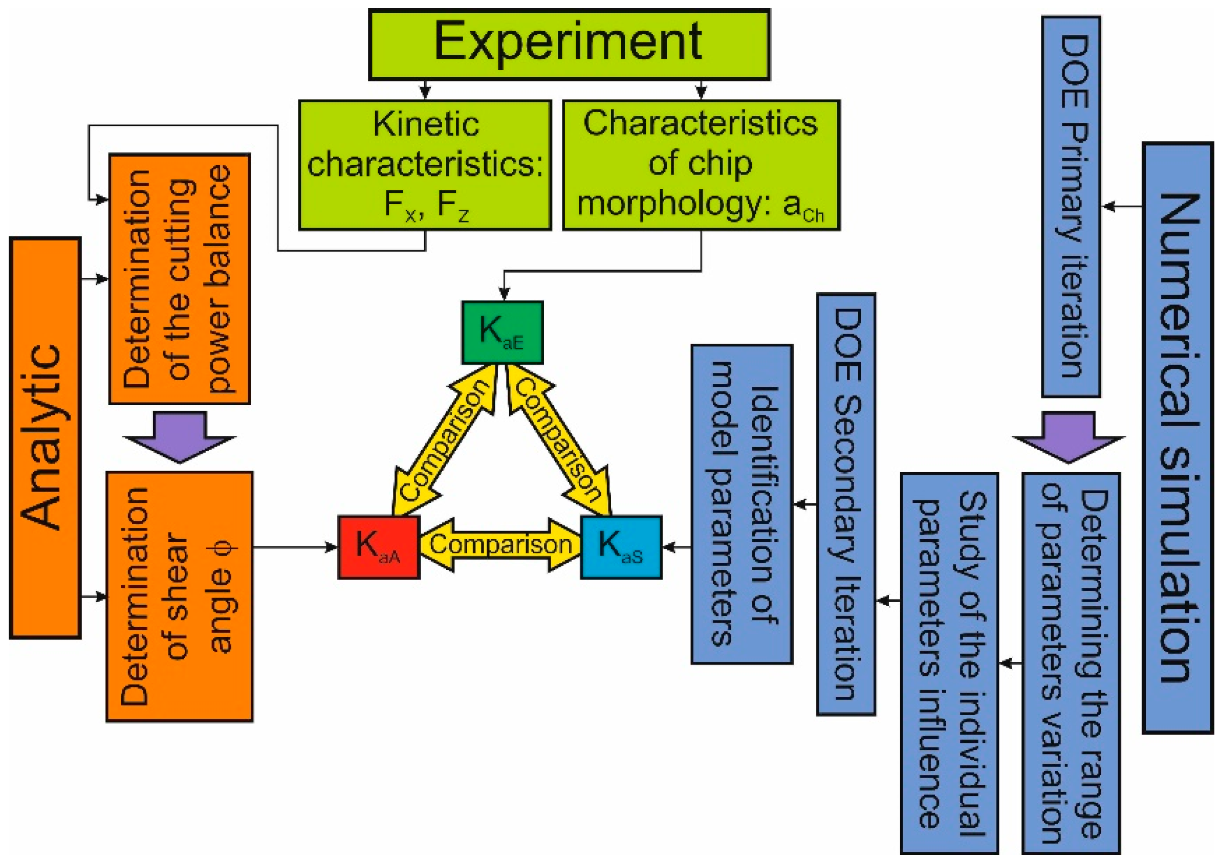
The methodology for performing chip compression ratio studies in the orthogonal cutting process is explained by the scheme shown in
Figure 1. Following this methodology, chip compression ratio
Ka is determined experimentally, analytically, and using the numerical modeling of the cutting process. The characteristic
Ka was defined as the ratio of chip thickness to cutting depth
a (undeformed chip thickness) [
7,
10,
68]:
Experimental studies include the measurement of cutting force components: cutting force
FX and thrust force
FZ, as well as the determination of chip morphological characteristics generated in the cutting process, in particular, chip thickness
aCh. As a result, the experimental chip compression ratio
KaE is determined according to dependence (1). The analytical determination of the chip compression ratio
KaA is performed using the analytical cutting model [
56]. For this purpose, the components of the total cutting power are determined (see
Figure 1, analytical part of the chip compression ratio methodology). Using the developed software-implemented algorithm, the minimum of the total cutting power is calculated at the given cutting parameters. Then, the value of the shear angle
ϕ corresponding to the specified minimum is found. The value of the shear angle is used to determine the desired value of the shear angle coefficient (see Equation (2)). The measured values of the cutting force components
FX and
FZ are used to determine the tangential stress
τS in the conventional shear plane. The determination of chip compression ratio by numerical modeling of
KaS was performed using the developed finite element model of the orthogonal cutting process [
69,
70].
To realize the numerical simulation of chip compression, the parameters of the machined material model are determined. This is accomplished through multiple iterations of DOE (Design of Experiment) sensitivity analysis and analysis of the influence of individual values of material model parameters (see
Figure 1, part of the methodology for numerical simulation of chip compression). The adequacy of the performed experimental studies, as well as analytical calculations and numerical modeling of the orthogonal cutting process, was checked at the final stage of the methodology for determining the chip compression ratio. This was performed by comparing the values of these characteristics determined experimentally, analytically, and by numerical modeling.
3.1. Materials
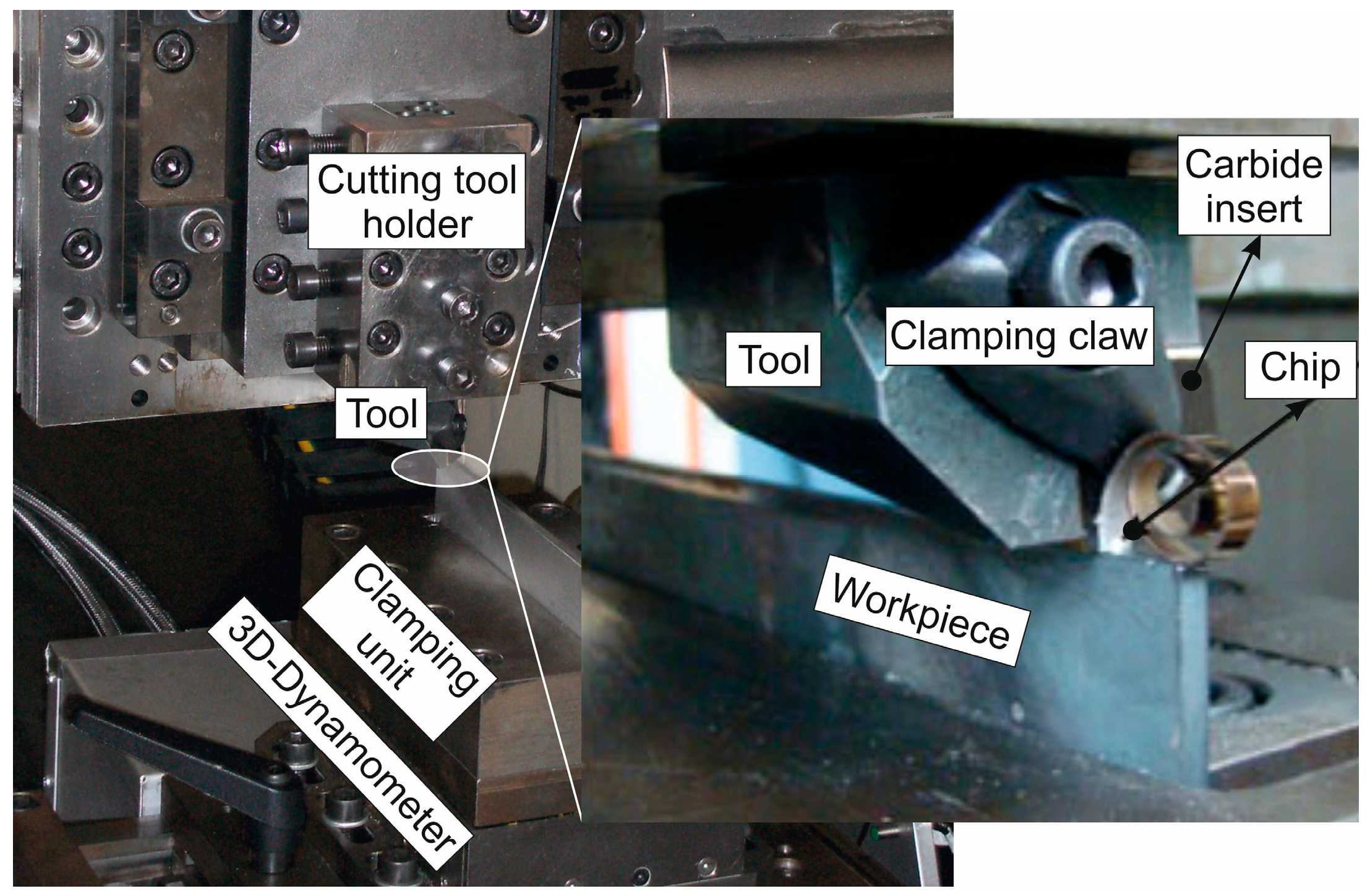
Experimental studies of the orthogonal cutting process were performed on a special machine [
70], as shown in
Figure 2. The cutting process was carried out dry. The cutting speed
VC was varied from 48 m/min to 192 m/min in increments of 48 m/min. The depth of cut
a was 0.2 mm for all tests. To measure the components of cutting forces
FX and
FZ, the dynamometer model 9121 by Kistler was used, on which the workpiece made of annealed and normalized steel AISI 1045 with hardness HB 1800 MPa was clamped. This steel was used as a machined material. A carbide insert SNMG-SM-1105 (ISO SNMG 15 06 12-SM 1105) from Sandvik Coromant, Sandviken, Sweden was used as the cutting element. The cutting wedge geometry of the tool required for the cutting process was ensured by positioning the cutting insert in the tool body and subsequent grinding and polishing of the clearance face of the insert. The mechanical and thermal properties of machined material and cutting elements are given in
Table 1. Six different rake angles,
λ: −15°, −10°, 0°, 10°, 15°, and 30°, were applied during the experimental studies of chip compression ratio. The clearance angle
a was 8° and the cutting edge radius of curvature
r was 20 µm in all studies. The cutting force components were measured for the following three different tool rake angles: −10°, 0°, and 10°. The choice of the number of different tool rake angles when measuring cutting force components is due to the fact that these measured cutting force components were later used as target values for numerical simulation of the cutting process in the sensitivity analysis of DOE. At the same time, it is assumed that the numerical modeling was performed for the above three different tool rake angles. Experimental studies for each value of cutting speeds and tool rake angles were repeated at least 5 times. The measurement error of the cutting force components did not exceed 8%.
To determine the chip compression ratio as well as the chip morphology, chips were prepared from the chips collected after each test (see
Figure 3a) [
72]. Chip thickness measurements and chip structure analysis were performed using a Carl Zeiss Axio Observer optical microscope. To analyze the chip microstructure, the surface of the chip was etched with 3% nitric acid (see
Figure 3b).
The chip thickness measurement error did not exceed 10%. This error is caused both by the heterogeneity of the chip’s mechanical properties at the microscopic level and by the difference between the studied specimens at the macroscopic level.
3.2. Methods
In parallel with experimental studies of chip compression, analytical calculations of this characteristic for the orthogonal cutting process and numerical simulation of chip compression were performed.
3.2.1. Analytical Determination of Chip Compression Ratio
Analytical determination of chip compression ratio was performed using the transformed dependence of shear angle determination [
10,
56,
69]. Thus, the specified cutting characteristic is determined by the values of the tool rake angle
g and shear angle
f:
The previously developed analytical cutting model [
56], based on the principle of potential energy minimum [
2,
21], was used to calculate the shear angle
f. The shear angle value was determined using the minimum of the cumulative cutting power
WC [
56,
69]:
where
is the existence space of cutting power components in the cutting process and
PC is the cutting power state of the cutting process.
As components of the cumulative cutting power, the power of plastic deformation of the machined material in the conditional shear plane
WS, friction power on the tool rake face friction power on the tool rake face
WFS, and friction power on the tool clearance
WFC were used [
56]:
The specified cutting power components were determined according to the following dependencies [
56]:
where
τS is the tangential stress in the conditional shear plane,
w is the cutting width,
fr is the friction coefficient on the tool rake face,
fC is the friction coefficient on the tool clearance face, and
lC is the wear mark value on the tool’s clearance face.
The value of tangential stress in the conditional shear plane
ts used in the calculation algorithm for determining the shear angle was performed using measured cutting force components
FX and
FZ [
69]:
where
FXC and
FZC are the cutting and thrust forces on the clearance face of the tool wedge, respectively, and
w is the cutting width.
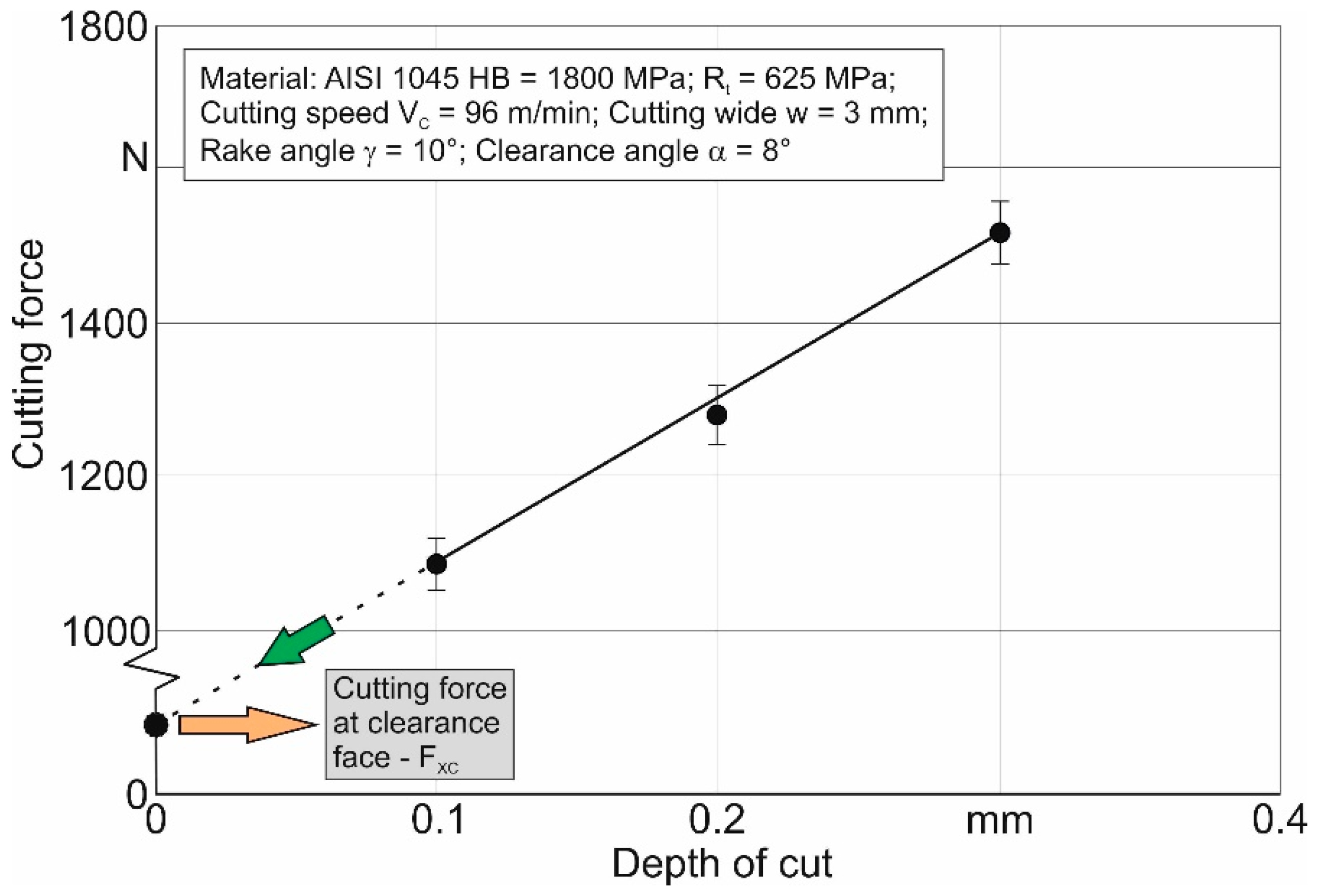
The cutting forces acting on the clearance face of the tool cutting wedge
FXC and
FZC were determined via extrapolation of the relationship between the measured cutting force components and the cutting depth
a to zero cutting depth [
68,
73]. The relationship between the measured cutting force components and the depth of cut, and the scheme for determining the force on the tool clearance face, is explained in
Figure 4.
The friction coefficients on the tool rake face
fr and the tool clearance face
fC were determined for the selected experimental conditions following the methodology [
74]. The determination of the shear angle according to principle (3) was performed using the previously developed software-implemented algorithm [
56]. As a result of using this algorithm, the value of the shear angle was found, which corresponded to the minimum cutting power at given cutting modes, tool geometric parameters, corresponding friction coefficients, and other initial parameters.
3.2.2. Numerical Modeling of Chip Compression Ratio
The determination of chip compression ratio by numerical modeling was carried out using the developed finite element model of the orthogonal cutting process based on the updated implicit Lagrangian formulation method. The FEM model of the process was developed in the DEFORM V 12.0 2D/3D™ software environment [
75]. It has been assumed that the workpiece material is isotropic plastic and the tool material is rigid. The geometric model with initial and boundary conditions is shown in
Figure 5. To realize the simulation of the cutting process, the bottom of the workpiece was rigidly fixed in all directions. The tool was rigidly fixed against movement in the
Z-axis direction and was able to move in the
X-axis direction. At the bottom of the workpiece and its left side, as well as at the right side of the tool and its tip, initial thermal conditions at room temperature
Tr were set. The working motion of the tool at cutting speed
VC and at cutting depth
a was given by absolute displacement in the negative direction along the
X-axis. The initial number of final workpiece elements was 8471 elements and 2173 nodes. The longest side length of the workpiece model element was about 0.0145 mm. The shortest side length of the workpiece model element was about 0.0063 mm. The initial number of finite tool elements was 1743 elements and 575 nodes. The side length of the largest tool model element was about 0.0135 mm, and the side length of its smallest element was about 0.0057 mm.
Figure 5 also shows a set of tools with different tool rake angles that were used in the cutting simulations. The Johnson–Cook constitutive equation [
76] was used as a material model [
77]. This constitutive equation is in the form of a multiplicative stress–strain relationship and depends on five parameters:
where
σs is the yield point,
A is the initial yield stress,
B is the stress coefficient of strain hardening,
n is the power coefficient of strain hardening,
C is the strain rate coefficient, m is the power coefficient of thermal softening,
ε is the strain,
is the strain rate,
is the reference value of the strain rate,
T is the actual temperature,
T0 is the reference or room temperature, and
Tm is the melting temperature of the material.
The model of contact interaction (friction model) between the tool and machined material [
78] is represented by the Coulomb model with different values of the friction coefficient in the contact of the tool with the chip and with the workpiece, i.e., in the secondary and tertiary cutting zones [
74]. The friction coefficients of the Coulomb model were determined from the local components of cutting forces acting in different cutting zones and their areas. These local friction coefficients were determined separately for the secondary and tertiary cutting zones. The required coefficients were determined separately for the plastic and elastic areas of the secondary cutting zone. Determination of local components of cutting forces is performed by separating these forces from the total cutting forces. Initially, the forces acting in the primary cutting zone are identified. Then local forces acting in the tertiary cutting zone are separated by extrapolating the dependence of the total forces on the cutting depth to zero (see, for example,
Figure 4). The last step in determining the local friction coefficients is to separate the local forces acting in the plastic and elastic areas of the secondary cutting zone. This is accomplished by reducing the length of the tool rake face through the grinding of its clearance face. Such grinding is carried out to achieve minimum cutting forces. A more detailed methodology for determining friction coefficients for the simulation of cutting processes is explained in [
74]. The developed numerical model of the orthogonal cutting process does not include the use of a special model of machined material damage [
79], as is necessary when machining titanium alloys [
72], austenitic steels, and other difficult-to-machine structural materials, due to the formation of serrated chips [
7,
10]. The separation of the machined material into chips and the machined surface of the workpiece, when the tool penetrates this material, is accomplished by remeshing the machined material organized by a calculation algorithm [
75].
4. Results and Discussion
The first step of the research according to the developed methodology (see
Figure 1) was to carry out experimental studies of the cutting forces’ components and chip compression with the above-mentioned changes in the cutting speeds and tool rake angles.
Figure 6 shows the dependencies of the cutting force components
FX and
FZ on the cutting speed for cutting angles equal to −10°, 0°, and 10°. The value of the measured cutting force components decreases monotonically with the increasing cutting speed. This is quite consistent with the well-known trend [
7,
10] and can be explained by the prevalence of the isothermal softening [
80] of the machined material over its adiabatic hardening [
73,
81]. The highest force values are observed at a tool rake angle of −10°. This is caused by the presence of higher values of the final true shear of the machined material in the cutting zones due to the higher plastic deformation of the material at the specified tool rake angle than at larger tool rake angles [
68,
73]. The lowest values of the cutting force components were observed at a tool rake angle equal to 10° because, at this tool rake angle, the lowest values of plastic deformation of the machined material in primary, secondary, and tertiary cutting zones are realized.
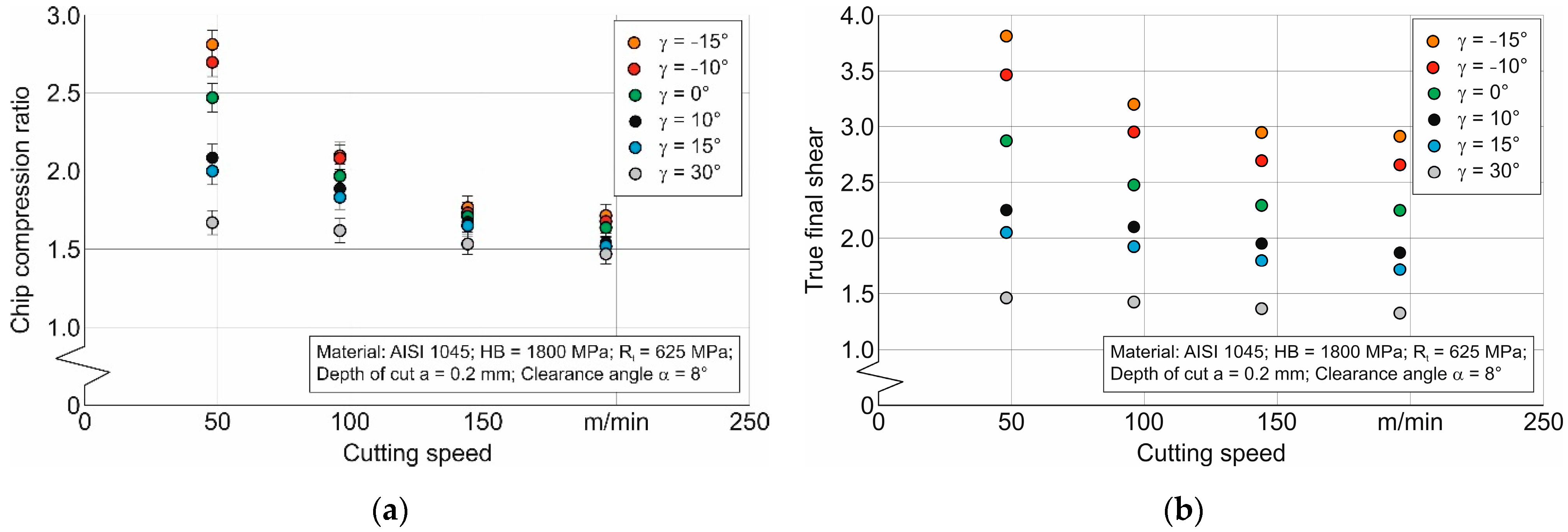
The effect of the cutting speed and tool rake angle on the chip compression ratio and true final shear of the machined material is shown in
Figure 7. The measured values of the chip compression ratio decrease monotonically with the increasing cutting speed, asymptotically nearing a certain limit (see
Figure 7a). This character of change in the influence of the cutting speed is sharply expressed for tool rake angles lying in the range from −15° to 0°.
The cutting process with such values of tool rake angles realizes the significant plastic deformation of the machined material in comparison to machining with positive tool rake angles. This is evidenced by the dependence of the calculated values in the true final shear of the machined material, as shown in
Figure 7b. In all probability, the considered character of the cutting speed effect on the chip compression ratio indicates the prevailing influence of the isothermal softening of the machined material, which grows with the increasing cutting speed [
68,
81]. At the same time, the plasticity reserve of the machined material is exhausted due to its high-speed hardening and large plastic deformations occurring during cutting with negative tool rake angles [
73]. In this case, the limit of chip compression ratio reduction (see
Figure 7a) is probably due to the opposition between the isothermal softening of the machined material and its adiabatic and strain rate hardening. The value of this limit is determined by the moment of reaching the limit value of plastic deformation, which occurs at the moment of exhaustion of the plastic limit.
The calculated chip compression ratio values, performed using an analytical cutting model [
56] following the developed research methodology (see
Section 3 and
Figure 1), are presented in
Figure 8. The dependence of the chip compression ratio on the cutting speed and the value of the tool rake angles corresponds to similar experimentally obtained dependences (see
Figure 7a): the chip compression ratio decreases with increasing the cutting speed. This reduction occurs up to some limit, presumably due, as mentioned above, to the exhaustion of the plasticity limit of the machined material. The calculated chip compression ratio values decrease as the tool rake angle increases. The magnitude of this reduction decreases with the increasing the cutting speed and at significant cutting speeds, the chip compression ratio values for different tool rake angles are almost identical (see
Figure 8a). In all probability, the chip compression coefficient is more influenced by the tangential stress value in the conditional shear plane, determined from measured cutting force components, than by other cutting parameters and characteristics included in the analytical cutting model. It is quite possible that this is the basis for the coincidence of the change pattern in the chip compression ratio determined experimentally and analytically.
The differences between the calculated values of the chip compression ratio and its measured values grow with increasing the cutting speed. At the same time, the highest values of these deviations are observed at a cutting speed of 192 m/min (see
Figure 8b). In all probability, this is explained by the fact that the analytical model of cutting, from which the chip compression ratio was calculated, does not take into account the hardening of the machined material due to the strain rate (speed) factor. In a real cutting process, an increase in the cutting speed contributes to some hardening of the machined material, which leads to a decrease in the chip compression ratio. This phenomenon is not yet taken into account in the known analytical cutting models. Nevertheless, the analytical determination of the above cutting characteristic may well be used as an alternative to experimental studies, since the deviations between the calculated and measured values do not exceed 21%.
The experimental determination of the chip compression ratio involves not only the realization of the cutting process with different cutting modes and different geometrical parameters of the tool cutting part, but also the collection and measurement of chips, preparation of splits, and so on. This is due to the significant time and cost involved. The use of analytical methods for chip compression ratio calculation is free from the mentioned disadvantages of experimental methods. However, the application of analytical methods is associated with significant assumptions assumed in the development of the analytical cutting model. This, of course, brings significant errors in determining the chip compression ratio. Numerical modeling methods are an alternative to experimental and analytical methods for determining the chip compression ratio. Among these methods, the finite element method is the most frequently used method for the numerical modeling of cutting. The application of this method for modeling cutting processes has developed rapidly in the last three decades [
2,
3]. This predestined the application of a numerical method for determining the chip compression ratio, which was the third stage of the developed methodology for determining this parameter (see
Section 3 and
Figure 1). The simulation results of a finite element model of cutting are significantly influenced by the model components, in particular, the material model and the friction model. Various methods are used to determine the parameters of the Johnson–Cook constitutive equation used as a material model (see
Section 3), among which experimental methods (see, e.g., [
82]) and inverse methods (see, e.g., [
83]) should be emphasized. In the present study, DOE (Design of Experiment) sensitivity analysis was used to determine the parameters of the constitutive equation. The cutting force component
FX was used as the target value of this analysis in determining the initial values of the above parameters for the first iteration of DOE. The initial values of the constitutive equation parameters used during the development of the numerical model of orthogonal cutting and the evaluation of its performance are given in
Table 2. For comparison, the values of the Johnson–Cook model parameters determined by other methods mentioned above are given in the same table.
Table 2 also summarizes the parameters of the friction model in different cutting zones and cutting areas (see
Section 3.2.2 “Numerical modeling of chip compression ratio”), which are further used to carry out simulations of the cutting process. The determination of the mentioned friction coefficients was performed through the methodology outlined in [
74]. The values of local friction coefficients given in
Table 2 are generalized (averaged over different tool rake angles).
Based on the initial values of the constitutive equation parameters that ensure a stable simulation process, the variation range of each of these parameters was selected for the first iteration of the DOE sensitivity analysis. The variation ranges of these parameters are summarized in
Table 3.
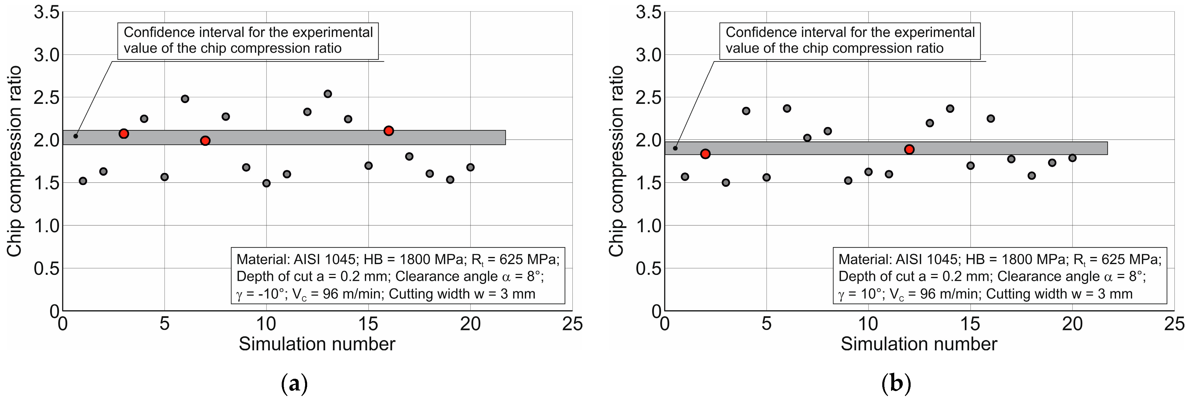
The results of the first iteration of the DOE sensitivity analysis with the initial values of the constitutive equation parameters and friction model parameters specified in
Table 2 are shown in
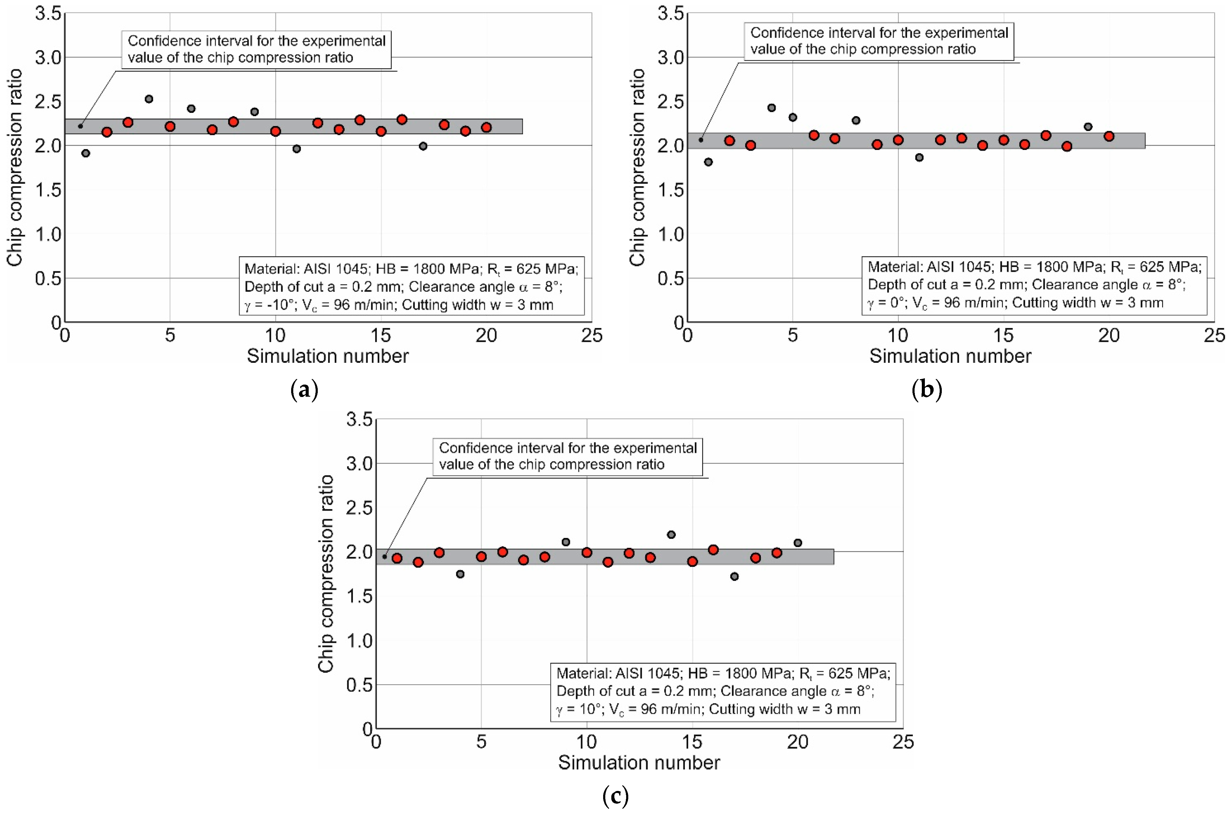
Figure 9. This figure shows that very few simulations fall within the confidence interval, i.e., the interval of the experimental chip compression ratio values, for both the negative tool rake angle and positive tool rake angle. This indicates the need to refine the selected range of constitutive equation parameters.
The influencing analysis of each parameter separately on the chip compression ratio is of considerable help in the process of specifying the variation range of the constitutive equation parameters [
70]. The results of this analysis are presented in the following three figures. In this case,
Figure 10 concentrates on the analysis results of the influence of hardening term parameters (Parameters A, B, and n) of the Johnson–Cook constitutive equation [
76,
77] on the chip compression ratio,
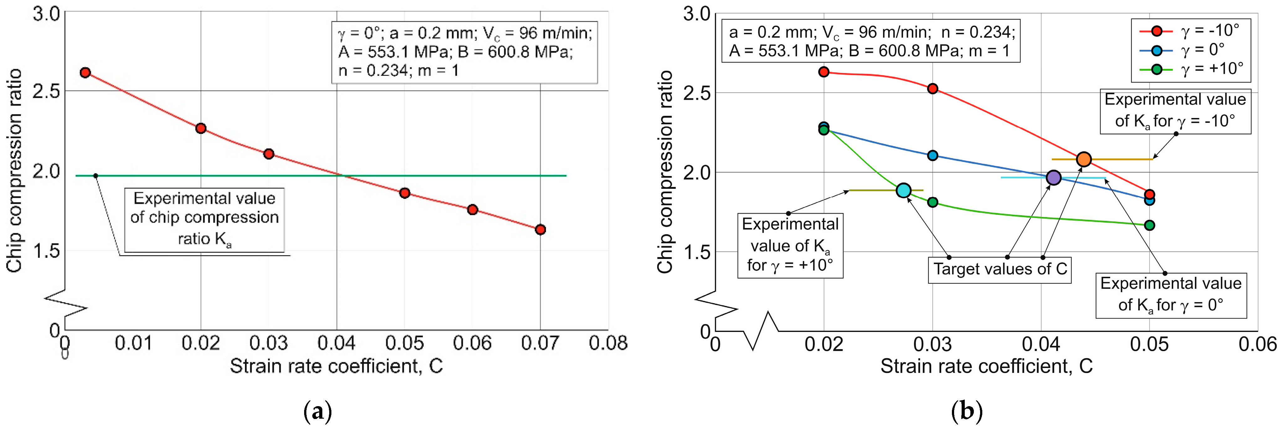
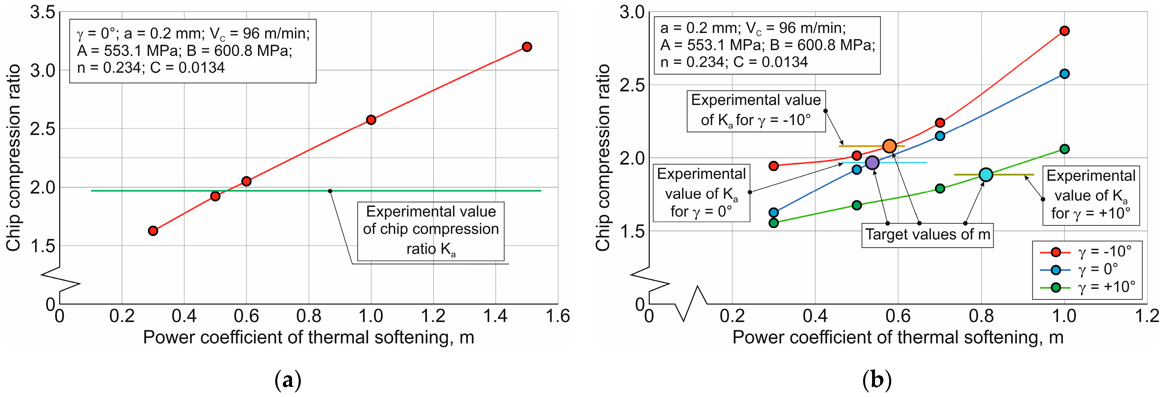
Figure 11 shows the influence of the strain rate term parameter (parameter C) on the investigated characteristic of the cutting process, and
Figure 12 shows the results of the influence of the thermic term parameter (parameter m) on the specified characteristic. In general, the above dependences demonstrate a significant influence of all three terms and, accordingly, of all five parameters of the constitutive equation on the chip compression ratio, within the considered limits of their variation. In this case, an increase in the initial yield stress (parameter A of hardening term) leads to a decrease in the chip compression ratio (see
Figure 10a). A similar effect, but to a somewhat lesser extent, is exerted by an increase in the stress coefficient of strain hardening (parameter B of the hardening term) (see
Figure 10c). At the same time, the power coefficient of strain hardening (parameter n) has a significant effect on the chip compression ratio (see
Figure 10e). However, increasing the parameter n between 0.2 and 0.4 entails a radical increase in the chip compression ratio. Subsequent increases in this parameter have a less noticeable effect on the chip compression ratio.
The considered influence of the hardening term parameters is exemplified by a tool rake angle of 0°. The above parameters’ effect of the constitutive equation on the chip compression ratio for all studied values of tool rake angles is shown in
Figure 10b,d,f. This joint influence of tool rake angles needs to be considered for the refined selection of the variation region of the constitutive equation parameters. It is noteworthy that different values of tool rake angles have quite different effects on the hardening term parameters. However, the values of these parameters for the considered rake angles corresponding to the target values indicated in the diagrams allow for estimating the desired variation limits of the constitutive equation parameters for subsequent iterations of the DOE sensitivity analysis.
It should be pointed out that the influencing patterns of the constitutive equation parameters on the chip compression ratio at simultaneous changes in the values of these parameters, realized in the process of DOE analysis, will be somewhat different than in the case of the considered change of individual parameters. Nevertheless, this analysis provides a preliminary estimate of the parameter variation limits. Taking into account the possible changes in these patterns, the required intervals should be extended.
As the strain rate coefficient (parameter C of the strain rate term) increases, the value of the chip compression ratio monotonically decreases—
Figure 11a. The extreme positions of the target values for the considered tool rake angles are used to estimate the limits of parameter C variation for the subsequent iterations of the DOE sensitivity analysis (see
Figure 11b).
An increase in the power coefficient of thermal softening (parameter m of the thermic term) entails a significant increase in the value of the chip compression ratio—
Figure 12a. Determined by the influence of the tool rake angle, the boundary values of parameter m provide an estimate of the variation interval of this parameter for subsequent iterations of the DOE sensitivity analysis (see
Figure 12b).
Based on the performed analysis, the limits of change in the constitutive equation parameters for subsequent DOE iterations were estimated. The final variation limits of the above parameters, taking into account the effect of different cutting speeds and the simultaneous variation of these parameters during the DOE sensitivity analysis, are given in
Table 4.
The results of the secondary iteration of the DOE sensitivity analysis at the variation limits of the constitutive equation parameters, specified in
Table 3 for all considered tool rake angles exemplarily for a cutting speed of 96 m/min, are shown in
Figure 13. The refined variation limits of the Johnson–Cook constitutive equation parameters, presented in
Table 4, enable a significantly better match between the simulated values of the chip compression ratio and the corresponding experimental values of this characteristic. This is evidenced by the fact that the overwhelming number of simulation results are within the confidence interval of the experimental chip compression ratio values.
The results of the secondary iteration of DOE sensitivity analysis allow finding the generalized values of the constitutive equation parameters, which provide for the considered values of tool rake angles and cutting speeds in the simulation of such values of the chip compression ratio, which are close enough to the corresponding experimental values. Such generalized values of the sought parameters are determined by using the previously developed software-implemented algorithm [
70]. These generalized values of the constitutive equation parameters are given in
Table 5.
The simulation of the chip compression ratio during orthogonal cutting at different cutting speeds and tool rake angles was performed with the generalized parameters of the Johnson–Cook constitutive equation shown in
Table 5. In this case, the parameters of the friction model in different cutting zones and their areas, as shown in
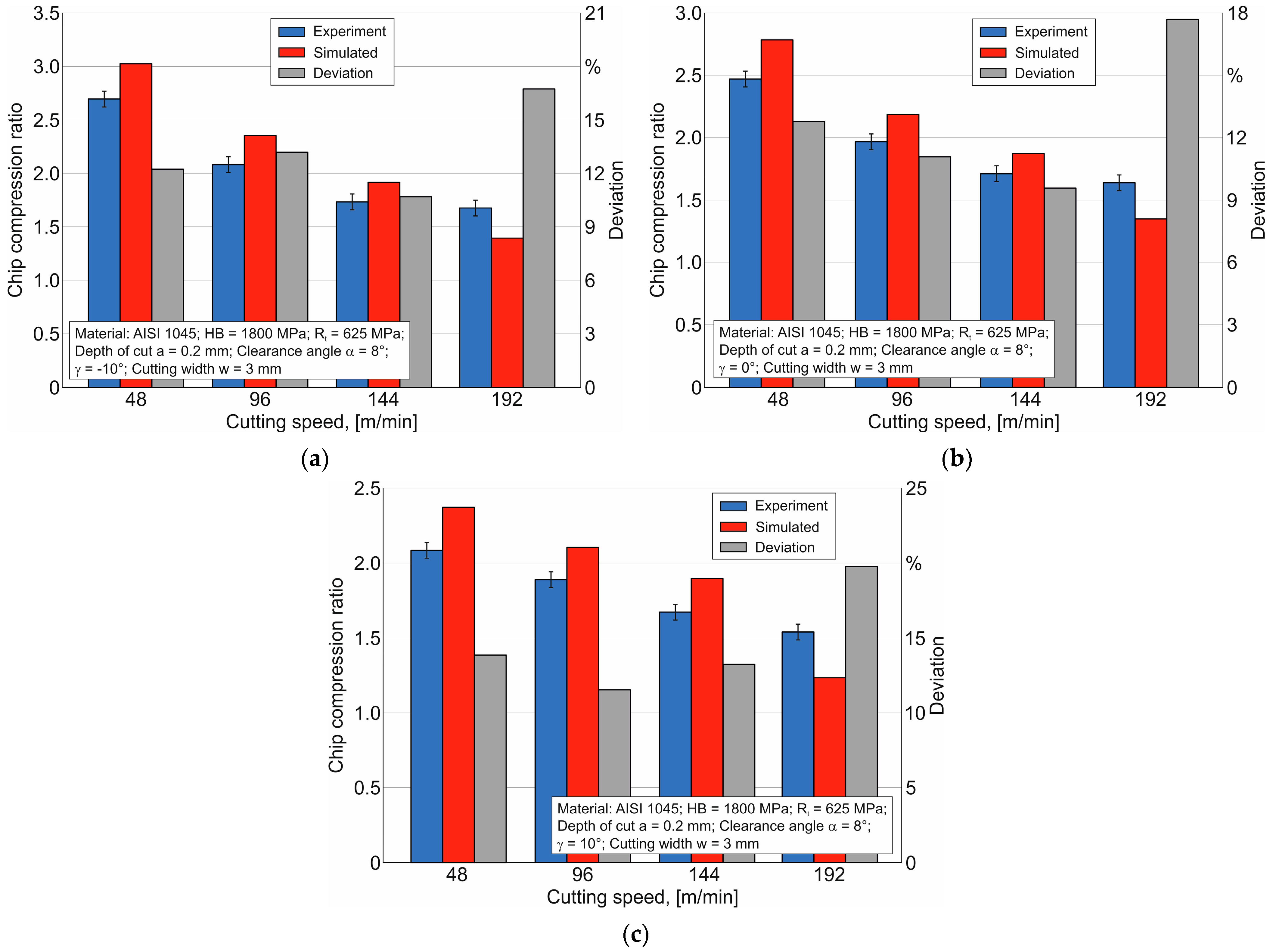
Table 2, were used. The results of these simulations are shown in
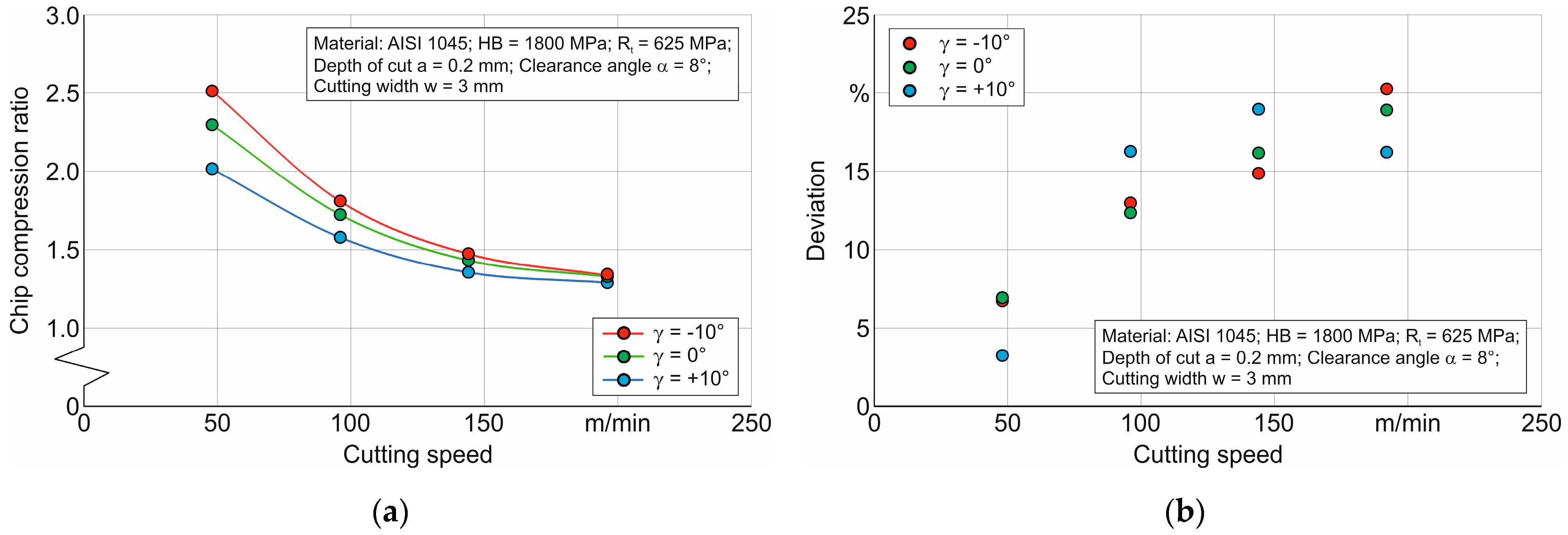
Figure 14. Together with the simulation results, the data of the experimental measurements of the chip compression ratio and deviations between them are also given in the above figure.
The deviation Δ between simulated and measured values was determined using the following equation:
The largest deviation between the simulated and measured values of the studied cutting characteristic is observed at a cutting speed equal to 192 m/min and is 16.74% for a tool rake angle equal to −10°. When the tool rake angle is equal to 0°, the specified deviation is 17.69%, and when the tool rake angle is equal to 10°, the deviation value between the measured and simulated chip compression ratio values is 19.77%. At lower cutting speeds, the deviation values between the measured and simulated values range from 12% to 14% (see
Figure 14). The main reasons for these deviations include the insufficient ability of the material model to simulate the process of the hardening and softening of the machined material at different cutting speeds. In addition, the description of the contact interaction between the tool and the machined material with the Coulomb friction model causes errors in the simulation process due to the mismatch between the simulated and real contact processes. Despite these shortcomings, the identified parameters of the constitutive equation and the friction model parameters provide a fairly good agreement between the measured and simulated chip compression ratio values, since the deviation between the specified results does not exceed 20%.
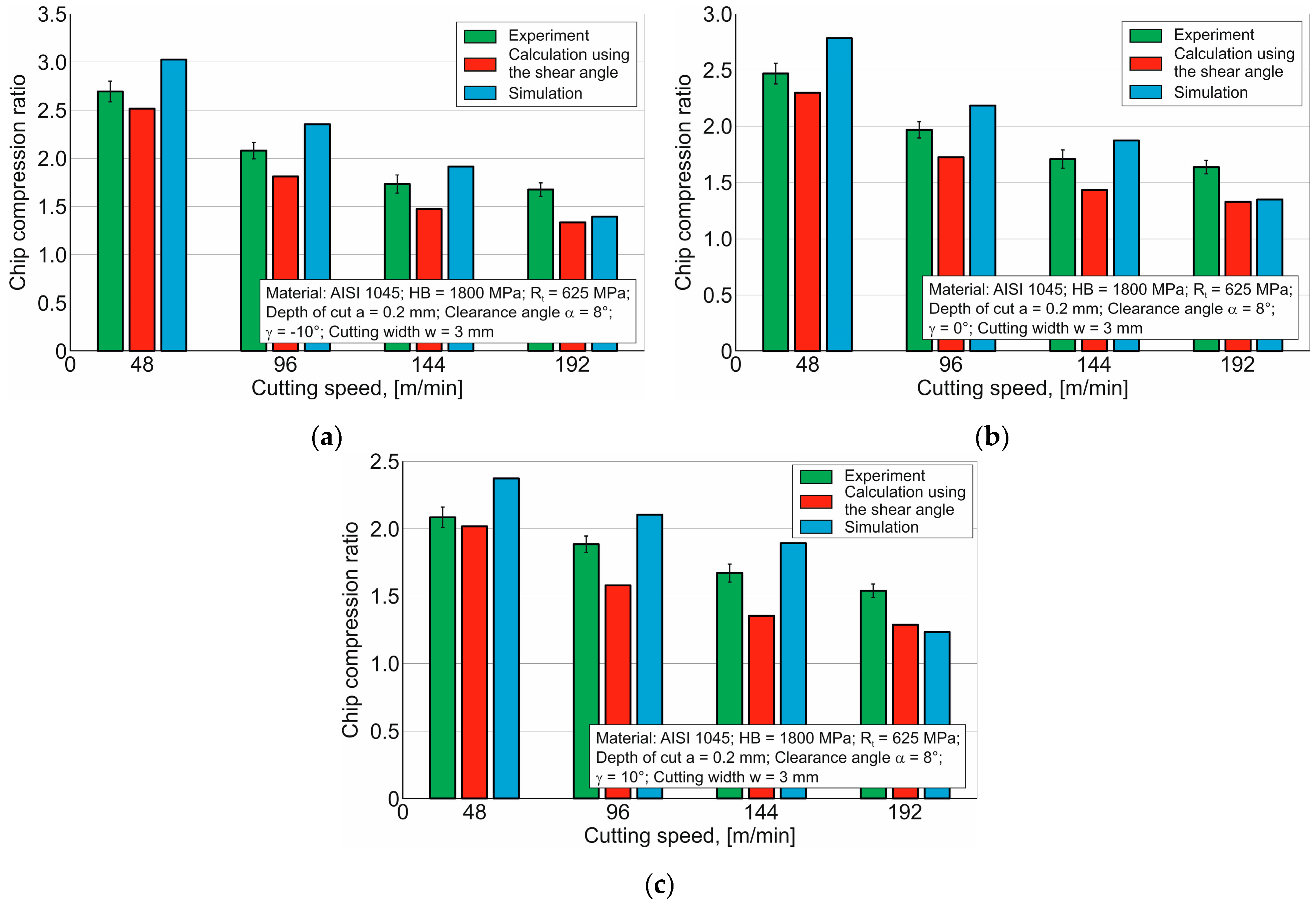
A comparison of the experimental values of the chip compression ratio with the corresponding values of this cutting characteristic determined by analytical calculations and numerical modeling is presented in
Figure 15. The results shown in the diagrams indicate that the analytically calculated values of the investigated cutting characteristic for almost all values of cutting speeds and tool rake angles are less than the corresponding experimental and simulated values.
The simulated values of the chip compression ratio overwhelmingly give the highest values of this characteristic for the investigated range of cutting speeds and tool rake angles. Thus, it can be summarized that the analytically calculated values of the chip compression ratio and its simulated values represent the boundary values of this characteristic for each set of cutting modes and tool rake angles. This enables a fairly accurate assessment of the chip compression ratio.
The carried out experimental, analytical, and simulation studies provide a fairly accurate possibility to estimate such an important cutting characteristic as the chip compression ratio. The established deviations between the values of the chip compression ratio determined by the specified methods do not exceed 22% in comparison with the measured values of this cutting process characteristic. Thus, the analytical algorithm and the developed methodology for the numerical determination of the chip compression ratio can be quite successfully applied to determine the above characteristic.
