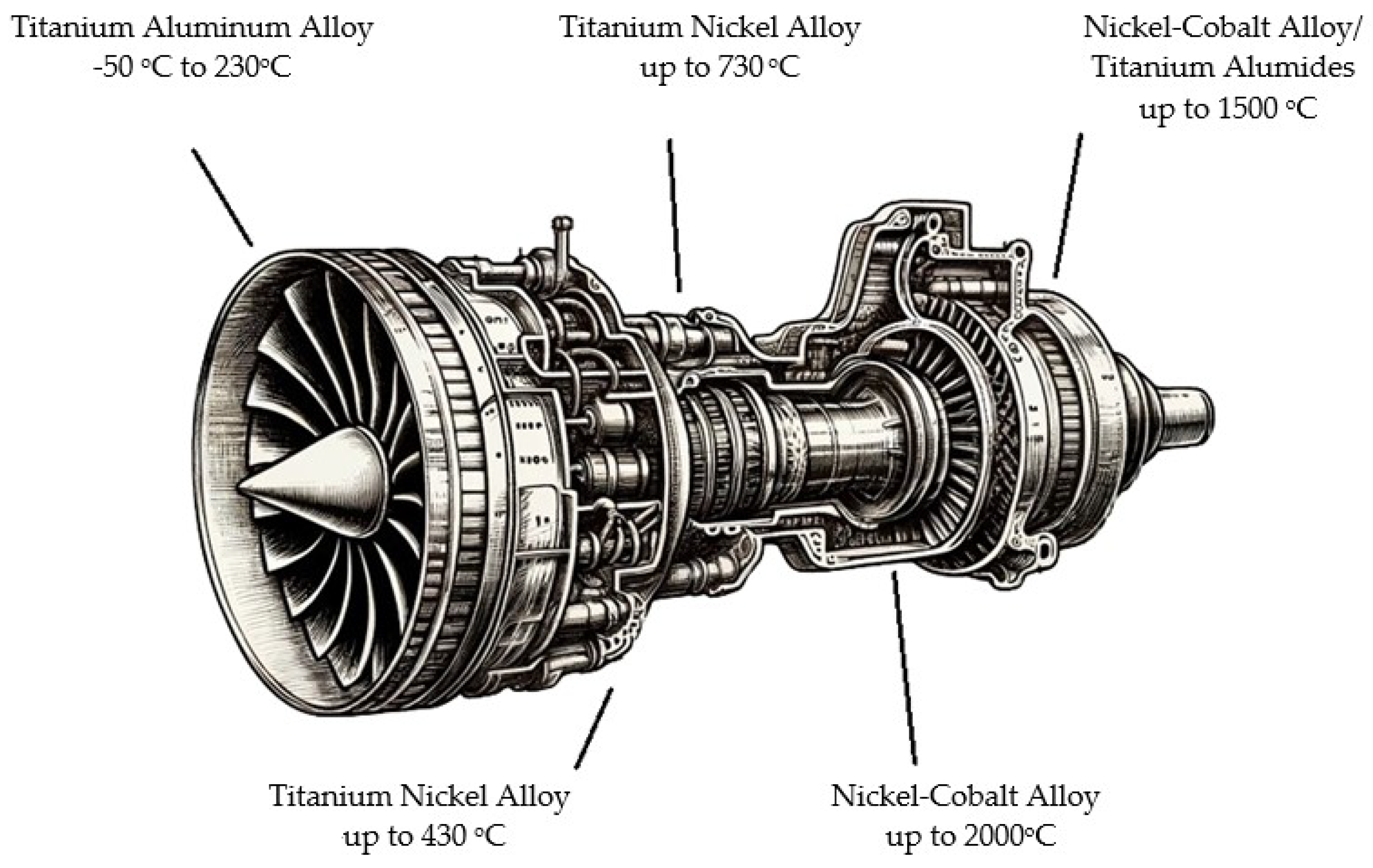
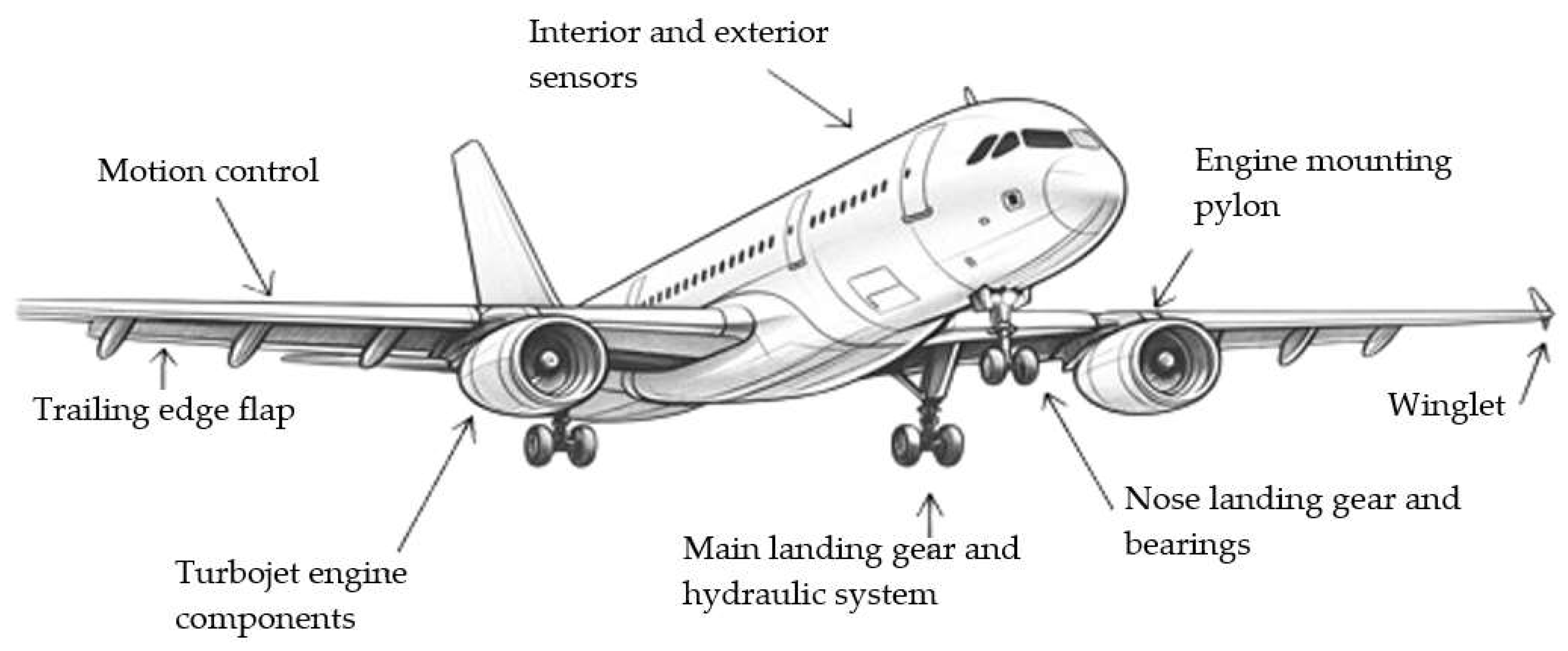
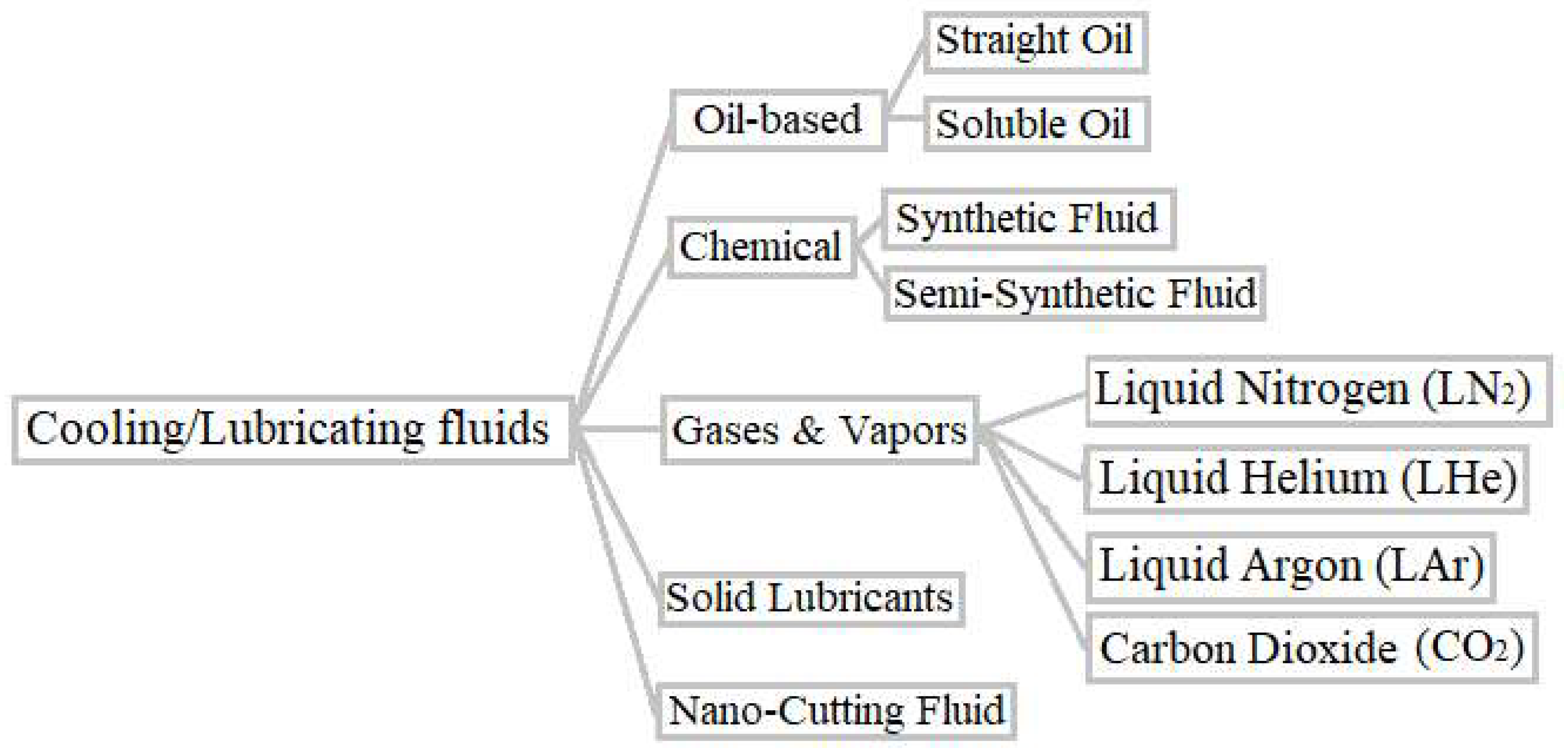
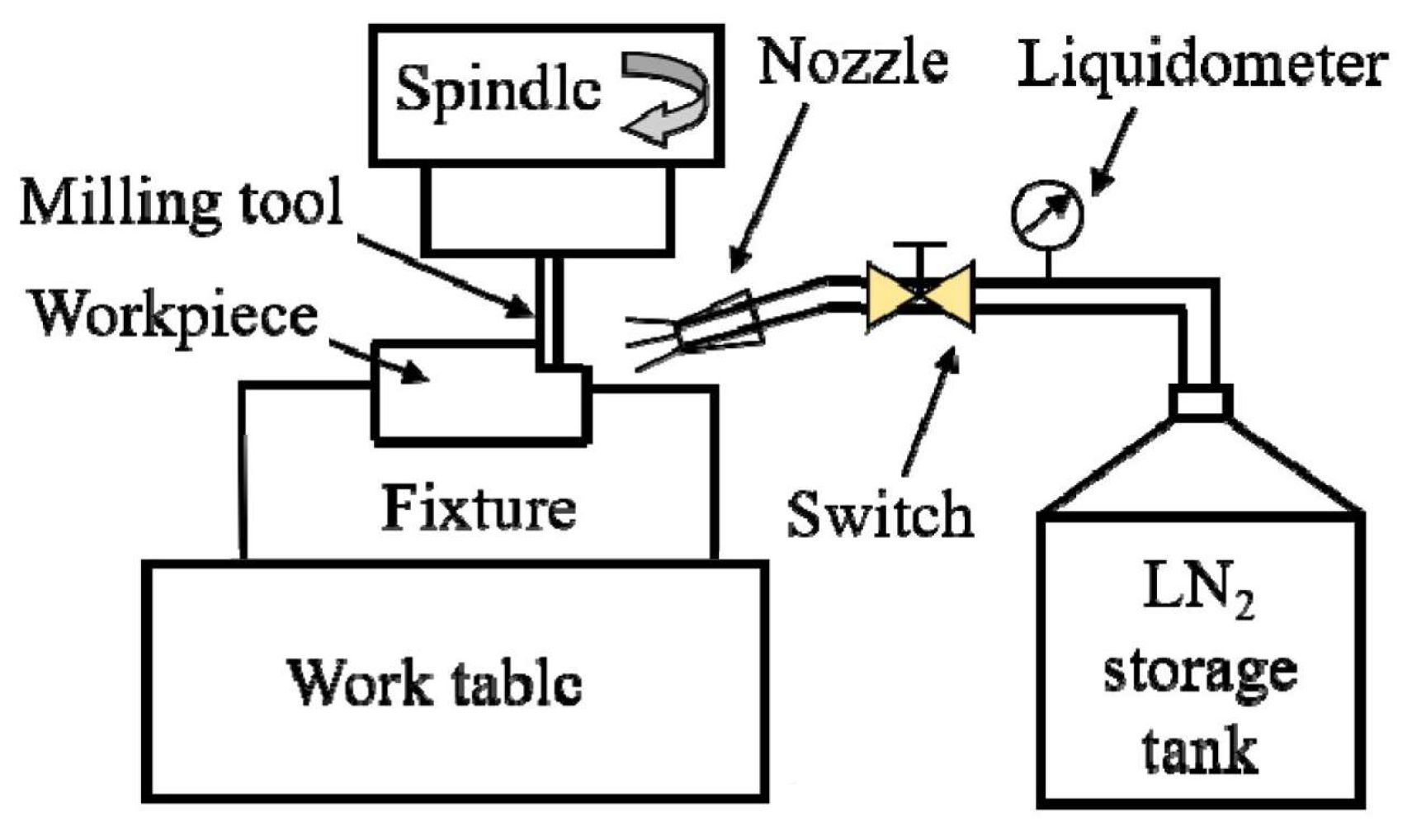
Review Regarding the Influence of Cryogenic Milling on Materials Used in the Aerospace Industry
Abstract
1. Introduction
2. Main Materials Used in the Aeronautical Industry
2.1. Aluminum Alloys
2.2. Titanium Alloys
| C | Fe | N | Al | O | V | H | Sn | Y | Zr | Mo | Si | Nb | Other | Ti | Refs. | |
|---|---|---|---|---|---|---|---|---|---|---|---|---|---|---|---|---|
| Titanium Ti6Al4V | <0.05 | <0.3 | <0.02 | 2.5–3.5 | <0.12 | 2–3 | <0.015 | - | <0.005 | - | - | - | - | 0.4 | Bal. | [55] |
| Titanium Ti3Al2.5V | <0.05 | < 0.2 | <0.05 | 2.5–3.5 | < 0.15 | 2–3 | <0.015 | - | - | - | - | - | - | 0.35 | Bal. | [57,58] |
| Titanium Ti5Al2.5V | <0.1 | <0.5 | <0.03 | 4–6 | <0.2 | - | <0.015 | 2–3 | - | - | - | - | - | 0.35 | Bal. | [51] |
| Titanium Ti6-2-4-2S | 5.5–6.5 | <0.25 | - | - | - | - | - | 1.8–2.2 | - | 3.6–4.4 | 1.8–2.2 | 0.06–0.12 | - | - | Bal. | [59] |
| IMI 834 | - | - | - | <5.8 | - | - | - | <4 | - | <3.5 | <0.5 | <0.35 | <0.7 | - | Bal. | [60] |
2.3. Nickel-Based Superalloys
2.4. Steel Alloys
2.5. Other Materials Used in Aircrafts
3. Cooling and Lubricating Fluids
4. Cryogenic Cooling
4.1. Delivery Methods in Cryogenic Cooling
4.2. Benefits and Features—Improved Machinability
- -
- Cooling materials to cryogenic temperatures can make them more brittle, which facilitates their cutting or machining, especially for tough or elastomeric materials but also for other materials such as titanium, inconel, or aluminum. Table 5 summarizes the papers that focus on the cryo-machining of materials used in the aerospace industry included in this review. The term “machinability” can be represented by the following criteria:
- -
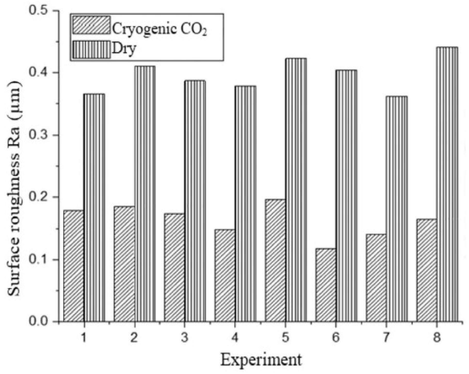
- Surface finish;
- -
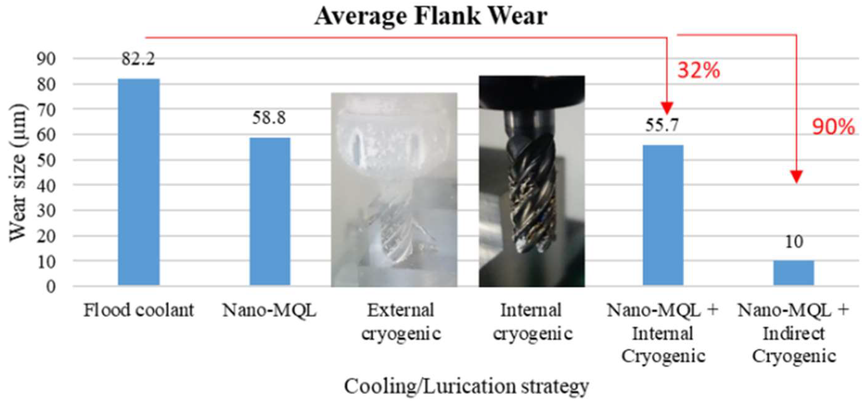
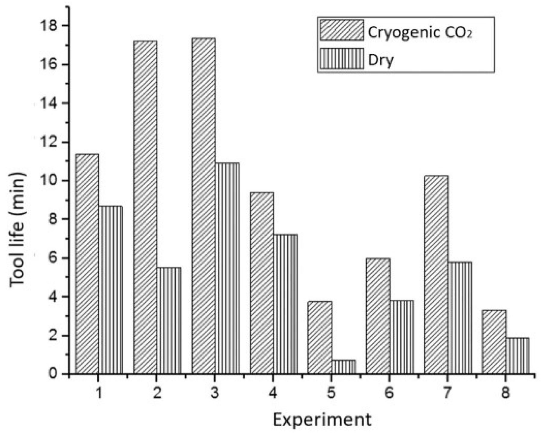
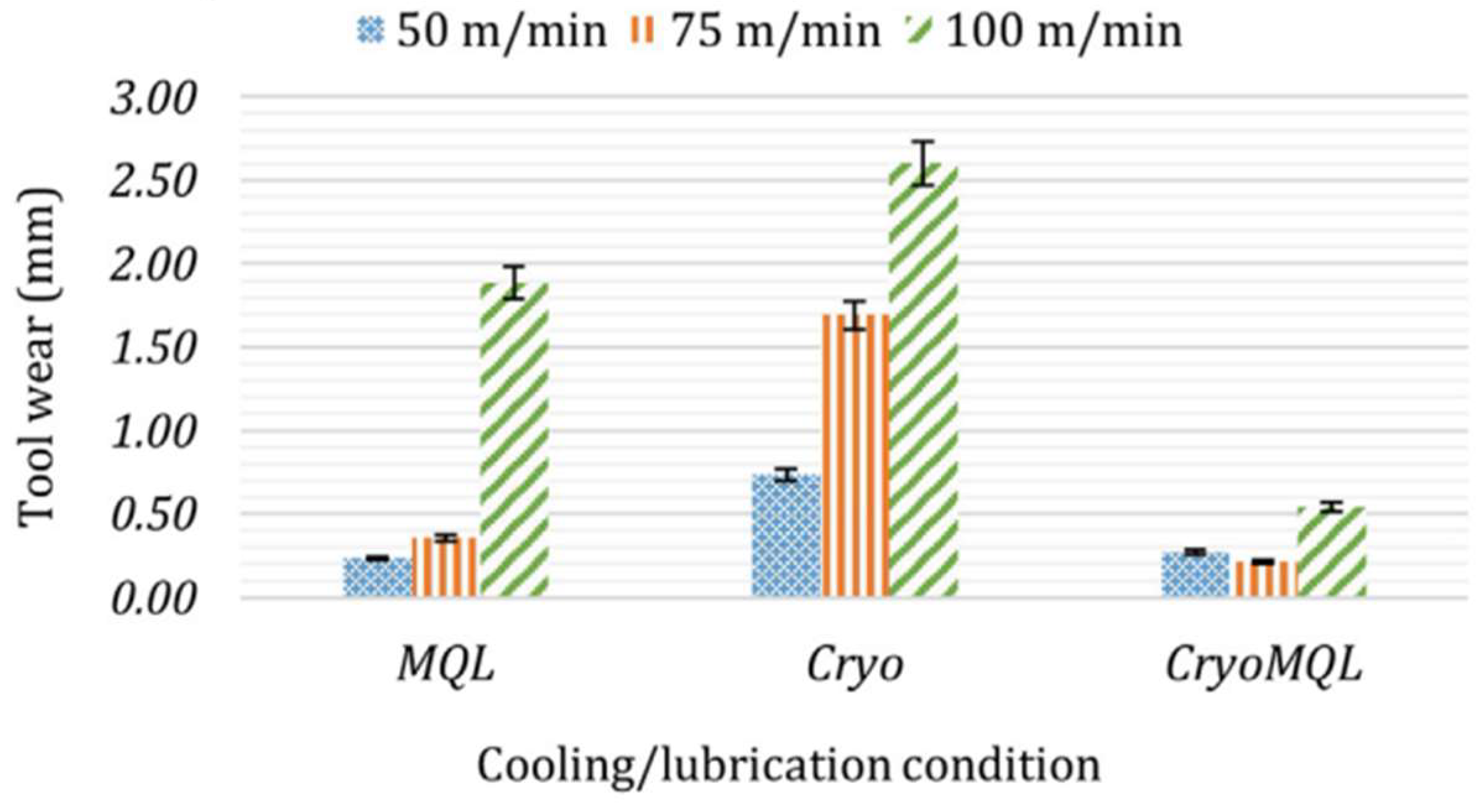
- Tool life;
- -
- Cutting force;
- -
- Chip shape;
- -
- Limiting rate of removed material [113].
| Reference | Workpiece Material | Machining Outputs | Cooling Method | Obs. |
|---|---|---|---|---|
| [84] | Al 6082 | Flank wear Crater wear Surface roughness Topography and texture of the machined surface | Dry machining MQL LCO2 MQL + LCO2 | |
| [102] | Al 6082-T6 | Cutting temperature Surface roughness Cutting forces Surface morphology Chip morphology Tool wear | LCO2 LN2 conventional wet machining | |
| [106] | Al 8011 | Cutting temperature Surface roughness Tool wear Chip morphology Microstructure analysis Hardness | Dry machining conventional wet machining LCO2 MQL MQL + LCO2 | |
| [114] | Al 7075 | Surface roughness Cutting temperature Cutting force | LN2 conventional wet machining | turning |
| [115] | Al 7075 | Cutting force Surface roughness Chip morphology Tool wear Surface roughness | Dry machining LCO2 MQL MQL + LCO2 | |
| [12] | Ti-6Al-4V | Cutting force | Dry machining LN2 | |
| [24] | Ti-6Al-4V | Cutting force Tool wear Tool performance | conventional wet machining nano-MQL LN2 (internal and external) nano-MQL + LN2 | |
| [83] | Ti-6Al-4V | Workpiece temperature Resulting forces Microhardness of the workpiece surface Surface topography | Dry machining LCO2 Sub-zero MWF | |
| [104] | Ti-6Al-4V | Cutting temperature Surface roughness Chip morphology Cutting forces Tool wear Microhardness | Conventional wet machining LCO2 MQL + LN2 | |
| [116] | Ti-6Al-4V | Surface roughness Tool wear Power consumption | Dry machining conventional wet machining cryogenic machining | |
| [117] | Ti-3Al-2.5V | Power consumption | Dry machining MQL LN2 MQL + LN2 | |
| [11] | Inconel 718 | Tool wear Cutting forces | MQL Conventional wet machining MQL + LCO2 | |
| [13] | Inconel 625 | Surface roughness Tool wear Cutting temperature Chip morphology | MQL LN2 MQL + LN2 | |
| [21] | Inconel 718 | Cutting force Tool wear | Conventional wet machining LCO2 (internal and external) MQL MQL + LCO2 | |
| [66] | Inconel 718 | Tool wear Surface roughness | Dry machining LCO2 | |
| [105] | Inconel 718 | Tool wear Energy consumption Chip reduction coefficient Surface roughness | Dry machining conventional wet machining LN2 | turning |
| [118] | Inconel 718 | Surface roughness Residual stress Chip morphology Cutting force Tool wear | Dry machining High pressure jet LN2 MQL Nano-MQL | turning |
| [119] | Inconel 718 | Surface roughness Tool wear Microhardness | Conventional wet machining MQL + LN2 | turning |
| [120] | Inconel 718 | Tool wear Surface roughness Chip morphology | Dry machining Conventional wet machining LCO2 MQL + LCO2 | turning |
| [121] | Inconel 718 | Tool wear Cutting forces Tool temperature | LCO2 internal and external | |
| [107] | AISI-4037 | Surface roughness Cutting temperature Dimensional deviation Pattern and chip formation mode Cutting force | Dry machining Conventional wet machining LN2 | turning |
| [122] | AISI 4340 | Surface roughness Cutting temperature | Dry machining LN2 | |
| [91] | AISI 4041 | Tool wear Cutting temperature | Dry machining LN2 LCO2 MQL MQL + LCO2 | turning |
| [103] | SiCp/Al composites | Cutting forces Chip morphology Surface topography | Dry machining LN2 |
4.2.1. Surface Finish
4.2.2. Tool Life
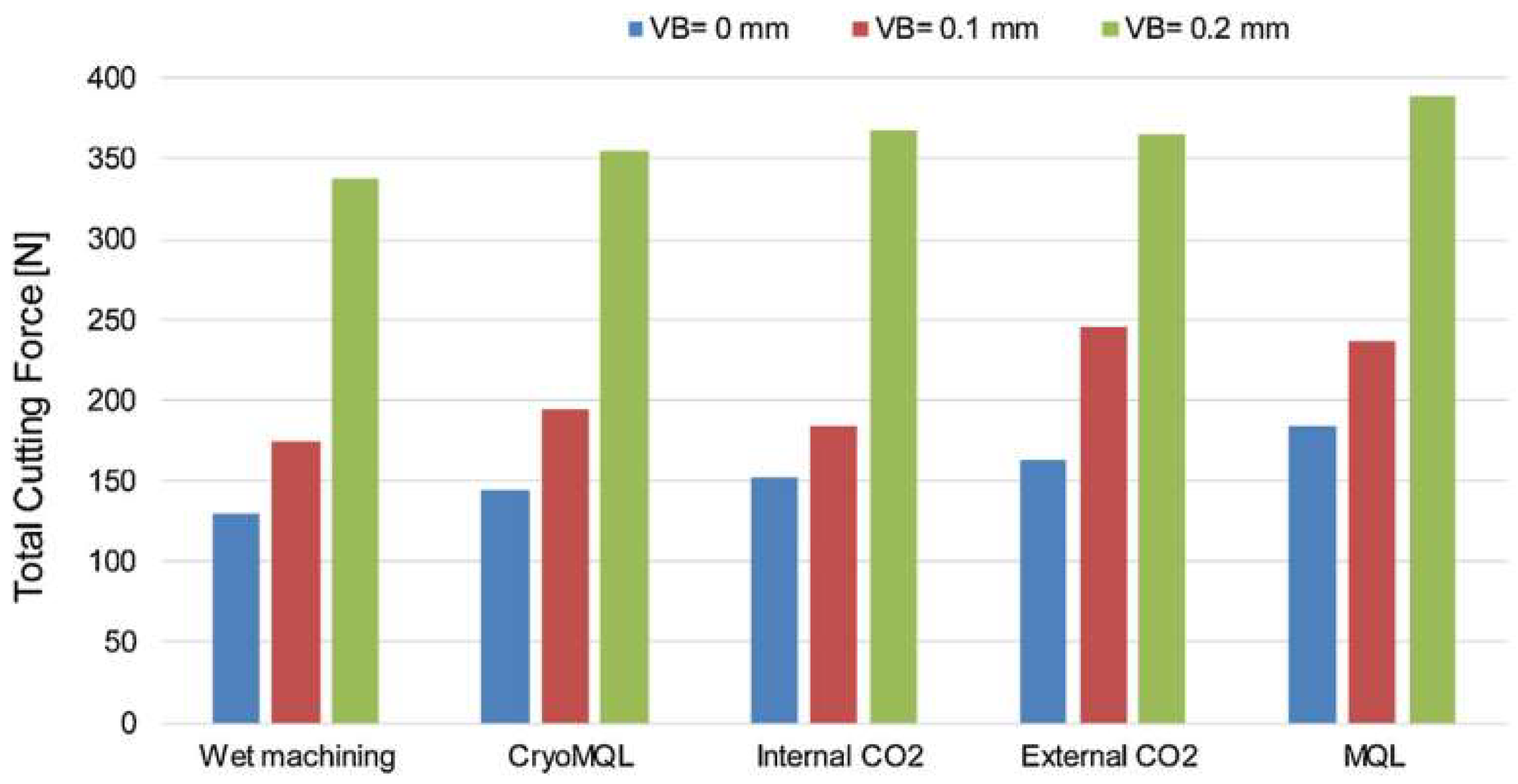
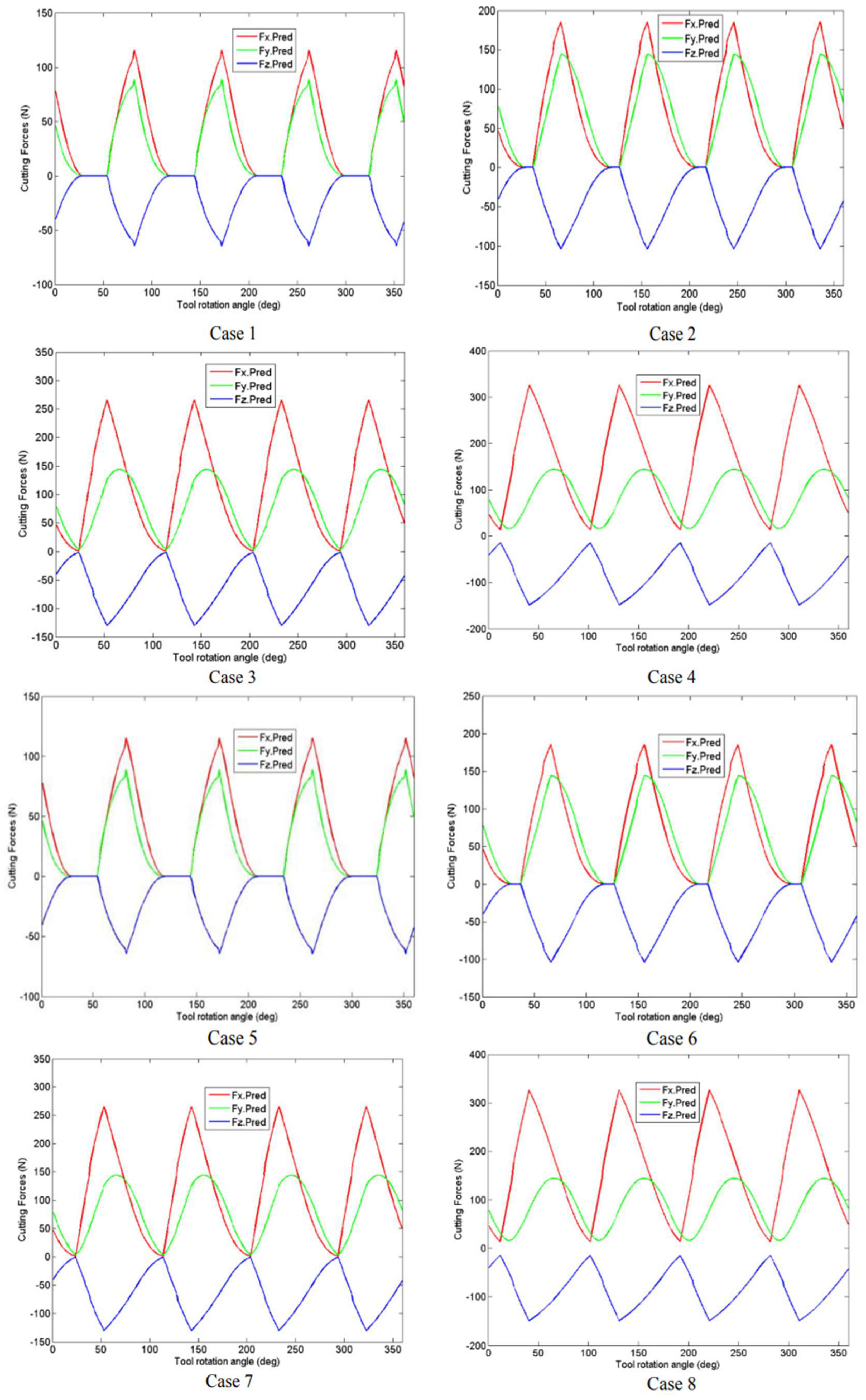
4.2.3. Cutting Force and Surface Stress
5. Conclusions
Author Contributions
Funding
Data Availability Statement
Conflicts of Interest
References
- Ackroyd, B.; Akcan, N.; Chhabra, P.; Krishnamurthy, K.; Madhavan, V.; Chandrasekar, S.; Compton, W.; Farris, T. Exploration of contact conditions in machining. Proc. Inst. Mech. Eng. Part B J. Eng. Manuf. 2001, 215, 493–507. [Google Scholar] [CrossRef]
- Kursun, C.; Gao, M.; Yalcin, A.O.; Parrey, K.A.; Gaylan, Y. Structure, mechanical, and neutron radiation shielding characteristics of mechanically milled nanostructured (100-x)Al-xGd2O3 metal composites. Ceram. Int. 2024, 50, 27154–27164. [Google Scholar] [CrossRef]
- Schmidt, J.; Thorenz, B.; Döpper, F. Design of a reference part for the comparison of tools in plastic milling operations. Procedia CIRP 2023, 119, 981–986. [Google Scholar] [CrossRef]
- Jayakumar, K. Optimization of cutting force and surface roughness in end milling of AA-TiCp composite. Mater. Today Proc. 2024. [Google Scholar] [CrossRef]
- Elmaraghy, W.; Elmaraghy, H.; Tomiyama, T.; Monostori, L. Complexity in engineering design and manufacturing. CIRP Ann. Manuf. Technol. 2012, 61, 793–814. [Google Scholar] [CrossRef]
- Saha, P.K. Aerospace Manufacturing Processes. Aeronaut. J. 2017, 121, 21–22. [Google Scholar] [CrossRef]
- Groover, M.P. Fundamentals of Modern Manufacturing: Materials, Processes, and Systems, 7th ed.; Wiley: Hoboken, NJ, USA, 2019. [Google Scholar]
- Lau, J.H.; Wong, C.P.; Prince, J.L. Electronic Packaging: Design, Materials, Process, and Reliability; McGraw-Hill: New York, NY, USA, 1998. [Google Scholar]
- Sheik Muhamad, S.; Ghani, J.; Haron, C.; Yazid, H. Cryogenic milling and formation of nanostructured machined surface of AISI 4340. Nanotechnol. Rev. 2020, 9, 1104–1117. [Google Scholar] [CrossRef]
- Zhang, X.; Mu, H.; Huang, X.; Fu, Z.; Zhu, D.; Ding, H. Cryogenic Milling of Aluminium-lithium Alloys: Thermo-mechanical Modelling towards Fine-tuning of Part Surface Residual Stress. Procedia CIRP 2015, 31, 160–165. [Google Scholar] [CrossRef]
- Pereira, O.; Urbikain, G.; Rodríguez, A.; Fernández-Valdivielso, A.; Calleja, A.; Ayesta, I.; de Lacalle, L.N.L. Internal cryolubrication approach for Inconel 718 milling. Procedia Manuf. 2017, 13, 89–93. [Google Scholar] [CrossRef]
- Elefanti, A.; Albertelli, P.; Strano, M.; Monno, M. Estimation of cutting and friction coefficients in dry and cryogenic milling through experiments and simulations. In AIP Conference Proceedings; AIP Publishing: Woodbury, NY, USA, 2019; Volume 2113. [Google Scholar] [CrossRef]
- Yıldırım, Ç.V.; Kıvak, T.; Sarıkaya, M.; Şirin, Ş. Evaluation of tool wear, surface roughness/topography and chip morphology when machining of Ni-based alloy 625 under MQL, cryogenic cooling and CryoMQL. JMR&T 2020, 9, 2079–2092. [Google Scholar] [CrossRef]
- Hardada, Y.; Hattori, S. Deep drawability of Ti/resin/Ti laminated sheet. In Proceedings of the International Conference of Global Network for Innovative Technology and Awam International Conference in Civil Engineering (IGNITE-AICCE’17): Sustainable Technology And Practice For Infrastructure and Community Resilience, Dublin, Ireland, 16 October 2017; Volume 1896, p. 080005. [Google Scholar]
- Sharma, V.S.; Dogra, M.; Suri, N.M. Cooling techniques for improved productivity in turning. Int. J. Mach. Tool. Manu. 2009, 49, 435–453. [Google Scholar] [CrossRef]
- Cassin, C.; Boothroyd, G. Lubricating action of cutting fluids. J. Mech. Eng. Sci. 1965, 7, 67–81. [Google Scholar] [CrossRef]
- Mazurkiewicz, M.; Kubala, Z.; Chow, J. Metal machining with high-pressure water-jet cooling assistance—A new possibility. J. Eng. Ind. 1989, 111, 7–12. [Google Scholar] [CrossRef]
- Pan, Z.; Yao, B.; Chen, B.; Huang, J.; Ma, X.; Lan, Q. Cutting force model of milling titanium alloy with C60 nanofluid minimum quantity lubrication. J. Man. Proc. 2023, 105, 295–306. [Google Scholar] [CrossRef]
- Sadeghifar, M.; Javidikia, M.; Loucif, A.; Jahazi, M.; Songmene, V. Experimental and numerical analyses of residual stress redistributions in large steel dies: Influence of tempering cycles and rough milling. J. Mater. Res. Technol. 2023, 24, 395–406. [Google Scholar] [CrossRef]
- Mohd Asmadi, N.A.N.; Zee, K.M.; Baskaran, S.M.; Ariffin, H.; Wasoh, H.; Maeda, T.; Hassan, M.A.; Zakaria, M.R. Rhamnolipids production by Pseudomonas aeruginosa RW9 using palm oil mill effluent sludge oil as a carbon source. Biocatal. Agric. Biotechnol. 2024, 57, 103069. [Google Scholar] [CrossRef]
- Pereira, O.; Celaya, A.; Urbikaín, G.; Rodríguez, A.; Fernández-Valdivielso, A.; De Lacalle, L.N.L.d. CO2 cryogenic milling of Inconel 718: Cutting forces and tool wear. J. Mater. Res. Technol. 2020, 9, 8459–8468. [Google Scholar] [CrossRef]
- Rao, S.; Sandeep, M.; Kumaraswami, R.; Shravan, A. A critical review on solid lubricants. IJMET 2016, 7, 193–199. [Google Scholar]
- Boopathi, S.; Elangovan, M.; Meka, U. Applications of Nano-Cutting Fluids in Advanced Machining in Processes. In Production, Properties, and Applications of Engineered Cementitious Composites; IGI Global: Hershey, PA, USA, 2023; pp. 211–234. [Google Scholar]
- Suhaimi, M.A.; Yang, G.-D.; Park, K.-H.; Hisam, M.J.; Sharif, S.; Kim, D.-W. Effect of Cryogenic Machining for Titanium Alloy Based on Indirect, Internal and External Spray System. Procedia Manuf. 2018, 17, 158–165. [Google Scholar] [CrossRef]
- Yildiz, Y.; Nalbant, M. A review of cryogenic cooling in machining processes. Int. J. Mach. Tool Manu. 2008, 48, 947–964. [Google Scholar] [CrossRef]
- Zheng Yang, K.; Pramanik, A.; Basak, A.K.; Dong, Y.; Prakash, C.; Shankar, S.; Dixit, S.; Kumar, K.; Ivanovich Vatin, N. Application of coolants during tool-based machining–A review. Ain Shams Eng. J. 2023, 14, 101830. [Google Scholar] [CrossRef]
- Kumar Gupta, M.; Korkmaz, M.E.; Sarıkaya, M.; Krolczyk, G.M.; Günay, M. In-process detection of cutting forces and cutting temperature signals in cryogenic assisted turning of titanium alloys: An analytical approach and experimental study. Mech. Syst. Signal Process. 2022, 169, 108772. [Google Scholar] [CrossRef]
- Khanna, N.; Wadhwa, J.; Pitroda, A.; Shah, P.; Schoop, J.; Sarıkaya, M. Life cycle assessment of environmentally friendly initiatives for sustainable machining: A short review of current knowledge and a case study. Sustain. Mater. Techno. 2022, 32, e00413. [Google Scholar] [CrossRef]
- Gupta, M.K.; Korkmaz, M.E.; Sarıkaya, M.; Krolczyk, G.M.; Günay, M.; Wojciechowski, S. Cutting forces and temperature measurements in cryogenic assisted turning of AA2024-T351 alloy: An experimentally validated simulation approach. Measurement 2022, 188, 110594. [Google Scholar] [CrossRef]
- Dixit, S.; Singh, P. Investigating the disposal of E-Waste as in architectural engineering and construction industry. Mater Today Proc. 2022, 56, 1891–1895. [Google Scholar] [CrossRef]
- Dixit, S.; Stefańska, A.; Musiuk, A.; Singh, P. Study of enabling factors affecting the adoption of ICT in the Indian built environment sector. Ain. Shams. Eng. J. 2021, 12, 2313–2319. [Google Scholar] [CrossRef]
- Jayakrishna, K.; Kar, V.R.; Sultan, M.T.H.; Rajesh, M. 1-Materials selection for aerospace components. In Sustainable Composites for Aerospace Applications; Jawaid, M., Thariq, M., Eds.; Woodhead Publishing: Sawston, UK, 2018; pp. 1–18. [Google Scholar]
- Aamir, M.; Giasin, K.; Tolouei-Rad, M.; Vafadar, A. A review: Drilling performance and hole quality of aluminium alloys for aerospace applications. J. Mater. Res. Technol. 2020, 9, 12484–12500. [Google Scholar] [CrossRef]
- Dursun, T.; Soutis, C. Recent developments in advanced aircraft aluminium alloys. Mater. Des. 2014, 56, 862–871. [Google Scholar] [CrossRef]
- Starke, E.A.; Staley, J.T. Application of modern aluminum alloys to aircraft. Prog. Aerosp. Sci. 1996, 32, 131–172. [Google Scholar] [CrossRef]
- Boyer, R.R.; Briggs, R.D. The use of β titanium alloys in the aerospace industry. J. Mater. Eng. Perform. 2005, 14, 681–685. [Google Scholar] [CrossRef]
- Li, S.S.; Yue, X.; Li, Q.Y.; Peng, H.L.; Dong, B.X.; Liu, T.S.; Yang, H.Y.; Fan, J.; Shu, S.L.; Qiu, F.; et al. Development and applications of aluminum alloys for aerospace industry. J. Mater. Res. Technol. 2023, 27, 944–983. [Google Scholar] [CrossRef]
- Aluminum and Aluminum Alloys. Metals Handbook Desk Edition, 2nd ed.; Davis, J.R., Ed.; ASM International: Almere, The Netherlands, 1998; pp. 417–423. [Google Scholar]
- Dhokia, V.; Chaharsooghi, A.S.; Paulino, D.C.; Newman, S.T. Effect of Cryogenic Cooling on the Surface Quality and Tool Wear in End Milling 6061-T6 Aluminium. In Proceedings of the Paper presented at 22nd International Conference on Flexible Automation and Intelligent Manufacturing (FAIM 2012), Helsinki, Finland, 10–13 June 2012. [Google Scholar]
- Heinz, A.; Haszler, A.; Keidel, C.; Moldenhauer, S.; Benedictus, R.; Miller, W.S. Recent development in aluminium alloys for aerospace applications. Mater. Sci. Eng. A 2000, 280, 102–107. [Google Scholar] [CrossRef]
- Sun, R.; Li, L.; Zhu, Y.; Guo, W.; Peng, P.; Cong, B.; Sun, J.; Che, Z.; Li, B.; Guo, C.; et al. Microstructure, residual stress and tensile properties control of wire-arc additive manufactured 2319 aluminum alloy with laser shock peening. J. Alloys Compd. 2018, 747, 255–265. [Google Scholar] [CrossRef]
- Gordon, J.V.; Haden, C.V.; Nied, H.F.; Vinci, R.P.; Harlow, D.G. Fatigue crack growth anisotropy, texture and residual stress in austenitic steel made by wire and arc additive manufacturing. Mater. Sci. Eng. A 2018, 724, 431–438. [Google Scholar] [CrossRef]
- Li, Q.; Wu, A.; Li, Y.; Wang, G.; Yan, D.; Liu, J. Influence of temperature cycles on the microstructures and mechanical properties of the partially melted zone in the fusion welded joints of 2219 aluminum alloy. Mater. Sci. Eng. A 2015, 623, 38–48. [Google Scholar] [CrossRef]
- Wang, G.; Zhao, Y.; Hao, Y. Friction stir welding of high-strength aerospace aluminum alloy and application in rocket tank manufacturing. J. Mater. Sci. Technol. 2018, 34, 73–91. [Google Scholar] [CrossRef]
- Araghchi, M.; Mansouri, H.; Vafaei, R.; Guo, Y. A novel cryogenic treatment for reduction of residual stresses in 2024 aluminum alloy. Mater. Sci. Eng. A 2017, 689, 48–52. [Google Scholar] [CrossRef]
- Bektaş, B.S.; Samtaş, G. Optimisation of cutting parameters in face milling of cryogenic treated 6061 aluminium alloy and effects on surface roughness, wear, and cutting temperatures. Surf. Topogr. Metrol. Prop. 2022, 10, 025013. [Google Scholar] [CrossRef]
- Tampu, C.; Chirita, B.; Cristea, I.; Zichil, V.; Schnakovszky, C.; Herghelegiu, E.; Carausu, C. Influence of cutting parameters on surface hardness in milling of AL6061T6. IOP Conf. Ser. Mater. Sci. Eng. 2020, 916, 012118. [Google Scholar] [CrossRef]
- Zhang, P.; Liu, Z.; Liu, J.; Yu, J.; Mai, Q.; Yue, X. Effect of aging plus cryogenic treatment on the machinability of 7075 aluminum alloy. Vacuum 2023, 208, 111692. [Google Scholar] [CrossRef]
- AZO Materials. Aluminum 7150 Alloy (UNS A97150). Available online: https://www.azom.com/article.aspx?ArticleID=8766 (accessed on 14 May 2024).
- MatWeb Material Property Data. Aluminum 7155 Composition Spec. Available online: https://www.matweb.com/search/datasheet.aspx?matguid=173f047427fe4b25a632f8ca59e7f35c&ckck=1 (accessed on 19 May 2024).
- Alloys International INC. Titanium 5-2.5 5Al-2.5Sn (Grade 6). Available online: https://alloysintl.com/titanium-alloys-supplier/titanium_5-2-5/ (accessed on 3 January 2024).
- Williams, J.C.; Boyer, R.R. Opportunities and Issues in the Application of Titanium Alloys for Aerospace Components. Metals 2020, 10, 705. [Google Scholar] [CrossRef]
- Donachie, M.J. Titanium: A Technical Guide; ASM International: Almere, The Netherlands, 2000. [Google Scholar]
- Welsch, G.; Boyer, R.; Collings, E. Materials Properties Handbook: Titanium Alloys; ASM International: Almere, The Netherlands, 1993. [Google Scholar]
- Lütjering, G.; Williams, J.C. Introduction. In Titanium; Lütjering, G., Williams, J.C., Eds.; Springer: Berlin/Heidelberg, Germany, 2003; pp. 1–11. [Google Scholar]
- NeoNickel. Titanium 6-2-4-2. Available online: https://www.neonickel.com/alloys/titanium-alloys/ti-6-2-4-2/ (accessed on 13 March 2024).
- Aircraft Materials. Titanium Alloy Grade 9/Ti-3Al-2.5V. Available online: https://www.aircraftmaterials.com/data/titanium/ti3al2-5v.html (accessed on 9 February 2024).
- AZO Materials. Grade 9 Ti 3Al 2.5V Alloy (UNS R56320). Available online: https://www.azom.com/article.aspx?ArticleID=9337 (accessed on 22 April 2024).
- Data, M.M.P. Titanium Ti-6Al-2Sn-4Zr-2Mo (Ti-6-2-4-2). Available online: https://www.matweb.com/search/datasheet.aspx?matguid=3a01802b122647028633c9fa10e6bae8 (accessed on 19 November 2023).
- MatWeb Material Property Data. Titanium IMI 834. Available online: https://www.matweb.com/search/DataSheet.aspx?MatGUID=a74096c99aa6486382a9c9e1be0883c4&ckck=1 (accessed on 13 March 2024).
- Saraçyakupoğlu, T. The novel manufacturing techniques of the airborne parts. In Theory and Research in Engineering II, 1st ed.; Kalkanci, M., Ed.; Gece Publishing: Kezlema, Turkey, 2020; pp. 179–194. [Google Scholar]
- Al-Nafeay, R.H.; Al-Roubaiy, A.O.; Omidvar, H. Overview of Joining and Repairing Techniques of Ni-Based Superalloy for Industrial Gas Turbine Applications. IOP Conf. Ser. Mater. Sci. Eng. 2021, 1094, 012141. [Google Scholar] [CrossRef]
- Donachie, M.J.; Donachie, S.J. Superalloys: A Technical Guide, 2nd ed.; ASM International: Almere, The Netherlands, 2002. [Google Scholar] [CrossRef]
- Reed, R.C. The Superalloys Fundamentals and Applications; Cambridge University Press: Cambridge, UK, 2006. [Google Scholar] [CrossRef]
- Singh, S. Superalloys Report. 2016. Available online: https://www.researchgate.net/publication/291336421_Superalloys_Report?channel=doi&linkId=56a06eb608aee4d26ad4107b&showFulltext=true#fullTextFileContent (accessed on 19 April 2024). [CrossRef]
- Halim, N.H.A.; Haron, C.H.C.; Ghani, J.A. PVD multi-coated carbide milling inserts performance: Comparison between cryogenic and dry cutting conditions. J. Manuf. Process. 2022, 73, 895–902. [Google Scholar] [CrossRef]
- Bhadeshia, H.K.D.H. Titanium Compositions. Available online: https://www.phase-trans.msm.cam.ac.uk/2003/Superalloys/superalloys.html (accessed on 19 April 2024).
- Continelntal Steel & Tube Company. Nickel Alloy X, Hastelloy® X. Available online: https://continentalsteel.com/nickel-alloys/grades/x-hastelloy-x/#:~:text=To%20be%20considered%20Nickel%20Alloy,Mo%208-10%25 (accessed on 3 February 2024).
- AZO Materials. Super Alloy HAYNES(r) 230 (UNS N06230). Available online: https://www.azom.com/article.aspx?ArticleID=7789 (accessed on 23 January 2024).
- Lu, Q.; Lai, Q.; Chai, Z.; Wei, X.; Xiong, X.; Yi, H.; Huang, M.; Xu, W.; Wang, J. Revolutionizing car body manufacturing using a unified steel metallurgy concept. Sci. Adv. 2021, 7, eabk0176. [Google Scholar] [CrossRef]
- Davis, J.R. Stainless Steels and Heat-Resistant Alloys. In Alloying: Understanding the Basics; ASM International: Almere, The Netherlands, 2001; pp. 255–344. [Google Scholar]
- Collins, J.A.; Busby, H.R.; Staab, G.H. Mechanical Design of Machine Elements and Machines: A Failure Prevention Perspective, 2nd ed.; Wiley: Hoboken, NJ, USA, 2009. [Google Scholar]
- Edacherian, A.; Ravi, B.; Joshi, S. Opportunities in Aerospace Casting Manufacture. In Proceedings of the 26th Indian Engineering Congress, Bangalore, India, 15–18 December 2011. [Google Scholar]
- Hall, J.N.; Fekete, J.R. Steels for auto bodies: A general overview. In Automotive Steels; Rana, R., Singh, S.B., Eds.; Elsevier: Amsterdam, The Netherlands, 2017; pp. 19–44. [Google Scholar]
- AZO Materials. AISI 4340 Alloy Steel (UNS G43400). Available online: https://www.azom.com/article.aspx?ArticleID=6772 (accessed on 22 January 2024).
- MatWeb. AISI 4037 Steel. Available online: https://www.matweb.com/search/datasheet.aspx?matguid=ff50824dfdb3463aa6edce95c175b3ce (accessed on 25 January 2024).
- Service Steel Aerospace. Maraging 300/VASCOMAX® 300 Steel-AMS 6514. Available online: https://www.ssa-corp.com/en/maraging-300-AMS-6514.php (accessed on 24 March 2024).
- Service Steel Aerospace. Maraging 250/VASCOMAX® 250 Steel-AMS 6512. Available online: https://www.ssa-corp.com/en/maraging-250-AMS-6512.php (accessed on 26 January 2024).
- Service Steel Aerospace. Maraging 350/VASCOMAX® 350 Steel-AMS 6515. Available online: https://www.ssa-corp.com/en/maraging-350-AMS-6515.php (accessed on 12 February 2024).
- McLaughlin, J.W.; Tobin, E.; O’Higgins, R.M. An investigation of Polyether Imide (PEI) toughening of carbon fibre-reinforced Polyether Ether Ketone (PEEK) laminates. Mater. Des. 2021, 212, 110189. [Google Scholar] [CrossRef]
- Gerstle, F.P. Composite Materials Science and EngineeringK.K. Chawla (Springer-Verlag, 1987). MRS Bulletin 1988, 13, 72. [Google Scholar] [CrossRef][Green Version]
- Matthews, F.L.; Rawlings, R.D. Composite Materials: Engineering and Science; CRC Press: Boca Raton, FL, USA, 1999. [Google Scholar]
- Gutzeit, K.; Bulun, G.; Stelzer, G.; Kirsch, B.; Seewig, J.; Aurich, J.C. Investigation of the surface integrity when cryogenic milling of Ti-6Al-4V using a sub-zero metalworking fluid. Procedia CIRP 2022, 108, 25–30. [Google Scholar] [CrossRef]
- Sivalingam, V.; Zhou, Q.; Sworna Ross, N.; Tiwari, S.; Selvam, B.; Sun, J.; Kumar Gupta, M. Identification of tool wear and surface morphology measurements in sustainable milling of Al 6082 hybrid metal matrix composite. J. Mater. Process. Technol. 2023, 27, 7570–7581. [Google Scholar] [CrossRef]
- Schoenitz, M.; Chintersingh, K.L.A.; Dreizin, E.L. Process-property correlations for spherical composite Al·Ti powders prepared by emulsion-assisted milling. Powder Technol. 2023, 428, 118806. [Google Scholar] [CrossRef]
- Du, F.; Zhou, T.; Tian, P.; Chen, J.; Zhou, X.; He, L.; Ren, A. Cutting performance and cutting fluid infiltration characteristics into tool-chip interface during MQL milling. Measurement 2024, 225, 113989. [Google Scholar] [CrossRef]
- Wu, S.; Liu, G.; Zhang, W.; Chen, W.; Wang, C. High-speed milling of hardened steel under minimal quantity lubrication with liquid nitrogen. J. Manuf. Process. 2023, 95, 351–368. [Google Scholar] [CrossRef]
- Van Sciver, S.W. Helium Cryogenics; Springer: New York, NY, USA, 2012. [Google Scholar]
- Willis, W.J.; Radeka, V. Liquid-argon ionization chambers as total-absorption detectors. Nucl. Instrum. Meth. 1974, 120, 221–236. [Google Scholar] [CrossRef]
- Vellaiyan, S.; Amirthagadeswarn, K.S.; Varun, B. Carbon Dioxide Capture Via Liquid Nitrogen in Compression Ignition Engine Nature Environment and Pollution Technology. Nat. Environ. Pollut. Technol. 2015, 14, 427–430. [Google Scholar]
- Kaynak, Y.; Gharibi, A. Progressive Tool Wear in Cryogenic Machining: The Effect of Liquid Nitrogen and Carbon Dioxide. J. Manuf. Mater. Process. 2018, 2, 31. [Google Scholar] [CrossRef]
- Krikke, H.R.; van der Laan, E. International journal of advanced manufacturing technology introduction to the special issue. Int. J. Adv. Manuf. Technol. 2010, 47, 413–414. [Google Scholar] [CrossRef]
- Jouhara, H.; Chauhan, A.; Guichet, V.; Delpech, B.; Abdelkareem, M.A.; Olabi, A.G.; Trembley, J. Low-temperature heat transfer mediums for cryogenic applications. J. Taiwan Inst. Chem. Eng. 2023, 148, 104709. [Google Scholar] [CrossRef]
- Davim, J.P. Machining: Fundamentals and Recent Advances; Springer: London, UK, 2008. [Google Scholar]
- Tinkham, M. Introduction to Superconductivity; Dover Publications INC: New York, NY, USA, 2004. [Google Scholar]
- Mazur, P. Kinetics of water loss from cells at subzero temperatures and the likelihood of intracellular freezing. J. Gen. Physiol. 1963, 47, 347–369. [Google Scholar] [CrossRef] [PubMed]
- Pegg, D.E. Principles of cryopreservation. Methods Mol. Biol. 2015, 1257, 3–19. [Google Scholar] [CrossRef]
- White, G.K.; Meeson, P.J. Experimental Techniques in Low-Temperature Physics, 4th ed.; Oxford University Press: Oxford, UK, 2002. [Google Scholar] [CrossRef]
- Global Climate Change. 10 Interesting Things about Air. Available online: https://climate.nasa.gov/news/2491/10-interesting-things-about-air/ (accessed on 25 October 2023).
- Shokrani, A.; Dhokia, V.; Newman, S.T. Comparative investigation on using cryogenic machining in CNC milling of Ti-6Al-4V titanium alloy. Mach. Sci. Technol. 2016, 20, 475–494. [Google Scholar] [CrossRef]
- Wang, X.; Zhang, X.; Pan, D.; Niu, J.; Fu, X.; Qiao, Y. Tool Wear and Surface Integrity of γ-TiAl Cryogenic Coolant Machining at Various Cutting Speed Levels. Lubricants 2023, 11, 238. [Google Scholar] [CrossRef]
- Jebaraj, M.; Kumar, M. Effect of cryogenic CO 2 and LN 2 coolants in milling of aluminum alloy. Mater. Manuf. Process. 2019, 34, 511–520. [Google Scholar] [CrossRef]
- Niu, Q.L.; Jing, L.; Yu, Z.; Li, C.P.; Qiu, X.Y.; Ko, T.J. Experimental study on cryogenic milling performance of SiCp/Al composites with liquid nitrogen. Mach. Sci. Technol. 2022, 26, 1–17. [Google Scholar] [CrossRef]
- Nimel Sworna Ross, K.; Ganesh, M. Performance Analysis of Machining Ti–6Al–4V Under Cryogenic CO2 Using PVD-TiN Coated Tool. J. Fail. Anal. Prev. 2019, 19, 821–831. [Google Scholar] [CrossRef]
- Khanna, N.; Agrawal, C.; Dogra, M.; Pruncu, C. Evaluation of tool wear, energy consumption, and surface roughness during turning of inconel 718 using sustainable machining technique. J. Mat. Res. Technol. 2020, 9, 5794–5804. [Google Scholar] [CrossRef]
- Ross, N.S.; Manasea Selvin, B.J.A.; Nagarajan, S.; Mashinini, P.M.; Dharmalingam, S.K.; Savio, A.P.; Gupta, M.K.; Korkmaz, M.E. Novel use of cryogenic cooling conditions in improving the machining performance of Al 8011/nano-SiC composites. Int. J. Adv. Manuf. Technol. 2023, 129, 1703–1715. [Google Scholar] [CrossRef]
- Dhar, N.R.; Kamruzzaman, M. Cutting temperature, tool wear, surface roughness and dimensional deviation in turning AISI-4037 steel under cryogenic condition. Int. J. Mach. Tool Manu. 2007, 47, 754–759. [Google Scholar] [CrossRef]
- Wang, F.; Wang, Y. Cleaner milling on Ti-6Al-4V alloy cooled by liquid nitrogen: External spray and inner injection. Int. J. Adv. Manuf. Technol. 2021, 112, 1193–1206. [Google Scholar] [CrossRef]
- Pereira, O.; Rodríguez, A.; Ayesta, I.; García, J.B.; Abia, A.I.F.; De Lacalle, L.N.L. A cryo lubri-coolant approach for finish milling of aeronautical hard-to-cut materials. Int. J. Mechatron. Manuf. Syst. 2016, 9, 370–384. [Google Scholar] [CrossRef]
- David, P.J. Nozzle Device and Method for Forming Cryogenic Composite Fluid Spray. U.S. Patent No 7,389,941, 24 June 2008. [Google Scholar]
- Tapoglou, N.; Aceves, M.; Cook, I.; Taylor, C. Investigation of the Influence of CO 2 Cryogenic Coolant Application on Tool Wear. Procedia CIRP 2017, 63, 745–749. [Google Scholar] [CrossRef]
- Busch, K.; Hochmuth, C.; Pause, B.; Stoll, A.; Wertheim, R. Investigation of Cooling and Lubrication Strategies for Machining High-temperature Alloys. Procedia CIRP 2016, 41, 835–840. [Google Scholar] [CrossRef]
- Wright, P.K.; Trent, E.M. Metal Cutting, 4th ed.; Butterworth-Heinemann: Boston, MA, USA, 2000. [Google Scholar]
- Muthuraman, V.; Arunkumar, S. Experimental evaluation of machining parameters in machining of 7075 aluminium alloy with cryogenic liquid nitrogen coolant. IOP Conf. Ser. Mater. Sci. Eng. 2017, 183, 012012. [Google Scholar] [CrossRef]
- Sivalingam, V.; Liu, H.; Tiwari, S.; Ganeshkumar, P.; Sun, M.; Kai, G.; Gupta, M.; Eltaggaz, A.; Raju, R. Effect of reinforced particles on the machinability of Al alloy under MQL, cryogenic, and hybrid lubrication. Int. J. Adv. Manuf. Technol. 2024, 132, 3349–3361. [Google Scholar] [CrossRef]
- Shokrani, A.; Dhokia, V.; Newman, S. Study of the effects of cryogenic machining on the machinability of Ti-6Al-4V titanium alloy. In Proceedings of the 12th EUSPEN International Conference, Stockholm, Sweden, 4–8 June 2012. [Google Scholar]
- Gupta, M.K.; Korkmaz, M.E.; Yılmaz, H.; Şirin, Ş.; Ross, N.S.; Jamil, M.; Królczyk, G.M.; Sharma, V.S. Real-time monitoring and measurement of energy characteristics in sustainable machining of titanium alloys. Measurement 2024, 224, 113937. [Google Scholar] [CrossRef]
- Behera, B.C.; Alemayehu, H.; Ghosh, S.; Rao, P.V. A comparative study of recent lubri-coolant strategies for turning of Ni-based superalloy. J. Manuf. Proces. 2017, 30, 541–552. [Google Scholar] [CrossRef]
- Iturbe, A.; Hormaetxe, E.; Garay, A.; Arrazola, P.J. Surface Integrity Analysis when Machining Inconel 718 with Conventional and Cryogenic Cooling. Procedia CIRP 2016, 45, 67–70. [Google Scholar] [CrossRef]
- Ostrowicki, N.; Kaim, A.; Gross, D.; Hanenkamp, N. Effect of various cooling lubricant strategies on turning Inconel 718 with different cutting materials. Procedia CIRP 2021, 101, 350–353. [Google Scholar] [CrossRef]
- Pereira, O.; Rodríguez, A.; Calleja-Ochoa, A.; Celaya, A.; de Lacalle, L.N.L.; Fernández-Valdivielso, A.; González, H. Simulation of Cryo-cooling to Improve Super Alloys Cutting Tools. Int. J. Precis. Eng. Manuf. 2022, 9, 73–82. [Google Scholar] [CrossRef]
- Sheik Muhamad, S.; Ghani, J.; Juri, A.; Hassan, C.; Haron, C. Dry and cryogenic milling of AISI 4340 alloy steel. J. Tribol. 2019, 21, 1–12. [Google Scholar]
- Baldin, V.; da Silva, L.R.; Davis, R.; Jackson, M.J.; Amorim, F.L.; Houck, C.F.; Machado, Á.R. Dry and MQL Milling of AISI 1045 Steel with Vegetable and Mineral-Based Fluids. Lubricants 2023, 11, 175. [Google Scholar] [CrossRef]
- Hanenkamp, N.; Amon, S.; Gross, D. Hybrid Supply System for Conventional and CO2/MQL-based Cryogenic Cooling. Procedia CIRP 2018, 77, 219–222. [Google Scholar] [CrossRef]
- Korkmaz, M.E.; Gupta, M.K. A State of the Art on Cryogenic Cooling and Its Applications in the Machining of Difficult-to-Machine Alloys. Materials 2024, 17, 2057. [Google Scholar] [CrossRef] [PubMed]
- Ma, Y.; Feng, P.; Zhang, J.; Wu, Z.; Yu, D. Prediction of surface residual stress after end milling based on cutting force and temperature. J. Mat. Proces. Technol. 2016, 235, 41–48. [Google Scholar] [CrossRef]
- Li, G.; Lu, W.; Huang, S.; Zhang, X.; Ding, S. Analysis and prediction of residual stresses based on cutting temperature and cutting force in rough turning of Ti–6Al–4V. Heliyon 2022, 8, e11661. [Google Scholar] [CrossRef]
- Jiang, X.; Li, B.; Wang, L.; Wang, Z.; Li, H. An approach to evaluate the effect of cutting force and temperature on the residual stress generation during milling. Int. J. Adv. Manuf. Technol. 2016, 87, 2305–2317. [Google Scholar] [CrossRef]
- Dhananchezian, M.; Kumar, M.P. Influence of cryogenic cooling in turning of AISI 1045 steel with modified cutting tool inserts. Int. J. Appl. Eng. Res. 2011, 6, 1721–1731. [Google Scholar]
- Kaynak, Y.; Lu, T.; Jawahir, I. Cryogenic Machining-Induced Surface Integrity: A Review and Comparison with Dry, MQL, and Flood-Cooled Machining. Mach. Sci. Technol. 2014, 18, 149–198. [Google Scholar] [CrossRef]
- Deshpande, Y.; Andhare, A.; Sahu, N. Estimation of surface roughness using cutting parameters, force, sound, and vibration in turning of Inconel 718. J. Braz. Soc. Mech. Sci. Eng. 2017, 39, 5087–5096. [Google Scholar] [CrossRef]





| Cu | Zn | Mg | Mn | Fe | Si | Cr | Ti | Al | Refs. | |
|---|---|---|---|---|---|---|---|---|---|---|
| Al 2024 | 3.8–4.9 | <0.25 | 1.2–1.8 | 0.3–0.9 | <0.5 | <0.5 | <0.1 | <0.15 | Bal. | [45] |
| Al 6061 | 0.15–0.4 | <0.25 | 0.8–1.2 | <0.15 | <0.7 | 0.4–0.8 | 0.04–0.35 | <0.15 | Bal. | [46,47] |
| Al 7075 | 1.2–2.0 | 5.1–6.1 | 2.1–2.9 | <0.3 | <0.5 | <0.4 | 0.18–0.28 | <0.2 | Bal. | [48] |
| Al 7150 | 1.2–1.9 | 7.2–8.2 | 2–2.9 | <0.2 | <0.2 | <0.15 | 0.1–0.22 | <0.1 | Bal. | [49] |
| Al 7155 | 2–2.6 | 7.6–8.4 | 1.8–2.3 | <0.1 | <0.25 | <0.25 | <0.05 | <0.1 | Bal. | [50] |
| Ni | Cr | Fe | Nb | Mo | Ti | Al | Mn | Si | C | Co | Other | Ref. | |
|---|---|---|---|---|---|---|---|---|---|---|---|---|---|
| Inconel 718 | 53 | 17 | 18.7 | 5.05 | 3.05 | 1.05 | 0.9 | 0.23 | 0.1 | 0.05 | - | Bal. | [66] |
| Waspaloy | Bal. | 19.5 | - | - | 4.3 | 3 | 1.3 | - | - | 0.08 | 13.5 | 0.006B 0.06Zr | [67] |
| Hastelloy X | Bal. | 22 | 18.5 | - | 9 | - | - | 0.5 | 0.5 | 0.1 | - | - | [68] |
| Inconel 625 | Bal. | 22 | 3 | 3.5 | 9 | 0.2 | 0.1 | - | - | 0.01 | 0.1 | - | [67] |
| Haynes 230 | Bal. | 22 | - | - | 2 | - | - | 1 | 0.5 | 0.075 | - | 12W | [69] |
| Rene 41 | Bal. | 19 | - | - | 10 | 3.1 | 1.5 | - | - | 0.09 | 11 | 0.05B | [67] |
| Fe | Ni | Cr | Mn | C | Mo | Si | S | P | Co | Other | Ref. | |
|---|---|---|---|---|---|---|---|---|---|---|---|---|
| AISI 4340 | 95–96 | 1.6–2 | 0.7–0.9 | 0.6–0.8 | 0.37–0.43 | 0.2–0.3 | 0.15–0.3 | 0.04 | 0.035 | - | - | [75] |
| AISI 4037 | 98–98.6 | - | - | 0.7–0.9 | 0.35–0.4 | 0.2–0.3 | 0.15–0.35 | <0.04 | <0.035 | - | - | [76] |
| AMS 6514 | Bal. | 18.5 | - | 0.1 | 0.03 | 4.8 | 0.1 | - | - | 9 | 0.6Ti 0.1Al | [77] |
| AMS 6512 | Bal. | 18.5 | - | 0.1 | 0.03 | 4.8 | 0.1 | - | - | 7.5 | 0.4Ti 0.1Al | [78] |
| AMS 6515 | Bal. | 18.5 | - | 0.1 | 0.03 | 4.8 | 0.1 | - | - | 12 | 1.4Ti 0.1Al | [79] |
| Runs | ||||||||
|---|---|---|---|---|---|---|---|---|
| 1 | 2 | 3 | 4 | 5 | 6 | 7 | 8 | |
| Cutting speed, Vc (m/min) | 120 | 120 | 130 | 130 | 140 | 140 | 140 | 140 |
| Feed rate, fz (mm/tooth) | 0.25 | 0.20 | 0.15 | 0.25 | 0.25 | 0.20 | 0.15 | 0.25 |
| Depth of cut, ap (mm) | 0.5 | 0.7 | 0.5 | 0.3 | 0.7 | 0.5 | 0.5 | 0.7 |
| Width of cut, ae (mm) | 0.4 | 0.2 | 0.2 | 0.2 | 0.4 | 0.4 | 0.2 | 0.4 |
Disclaimer/Publisher’s Note: The statements, opinions and data contained in all publications are solely those of the individual author(s) and contributor(s) and not of MDPI and/or the editor(s). MDPI and/or the editor(s) disclaim responsibility for any injury to people or property resulting from any ideas, methods, instructions or products referred to in the content. |
© 2024 by the authors. Licensee MDPI, Basel, Switzerland. This article is an open access article distributed under the terms and conditions of the Creative Commons Attribution (CC BY) license (https://creativecommons.org/licenses/by/4.0/).
Share and Cite
Nita, B.; Tampu, R.I.; Tampu, C.; Chirita, B.A.; Herghelegiu, E.; Schnakovszky, C. Review Regarding the Influence of Cryogenic Milling on Materials Used in the Aerospace Industry. J. Manuf. Mater. Process. 2024, 8, 186. https://doi.org/10.3390/jmmp8050186
Nita B, Tampu RI, Tampu C, Chirita BA, Herghelegiu E, Schnakovszky C. Review Regarding the Influence of Cryogenic Milling on Materials Used in the Aerospace Industry. Journal of Manufacturing and Materials Processing. 2024; 8(5):186. https://doi.org/10.3390/jmmp8050186
Chicago/Turabian StyleNita, Bogdan, Raluca Ioana Tampu, Catalin Tampu, Bogdan Alexandru Chirita, Eugen Herghelegiu, and Carol Schnakovszky. 2024. "Review Regarding the Influence of Cryogenic Milling on Materials Used in the Aerospace Industry" Journal of Manufacturing and Materials Processing 8, no. 5: 186. https://doi.org/10.3390/jmmp8050186
APA StyleNita, B., Tampu, R. I., Tampu, C., Chirita, B. A., Herghelegiu, E., & Schnakovszky, C. (2024). Review Regarding the Influence of Cryogenic Milling on Materials Used in the Aerospace Industry. Journal of Manufacturing and Materials Processing, 8(5), 186. https://doi.org/10.3390/jmmp8050186


