1. Introduction
The rising prevalence of internal combustion vehicles, reliant on non-renewable conventional fuels, has given rise to both energy and environmental concerns. Consequently, numerous nations have adopted new energy vehicles as substitutes for traditional vehicles, aiming to diminish the reliance on oil and mitigate air pollution [
1]. Governments worldwide are implementing stringent policies to reduce CO
2 emissions and combat climate change. For instance, the UK’s commitment to achieving net-zero greenhouse gas emissions by 2050, as outlined in the report “Absolute Zero: Delivering the UK’s Climate Change Commitment with Incremental Changes to Today’s Technologies,” highlights the urgency of transitioning to low-carbon technologies, including EVs. These policies drive the adoption of EVs, which are crucial in reducing transportation-related emissions, a significant contributor to overall CO
2 emissions [
2].
Electric vehicles have emerged as a prominent and environmentally friendly alternative to conventional internal combustion engine vehicles. They have become a cornerstone of modern transportation, driven by the urgent need to reduce greenhouse gas emissions and reliance on non-renewable energy sources. The transition from internal combustion engine vehicles to EVs promises significant environmental and economic benefits. However, the widespread adoption of EVs faces several challenges, including cost, range anxiety, and the need for advancements in battery technology. The categories of EVs encompass pure electric vehicles [
3], hybrid electric vehicles [
4], and fuel cell electric vehicles [
5]. A pure electric vehicle, often referred to as a battery electric vehicle, operates solely on power derived from a traction battery [
6].
Range anxiety, the fear that an EV will not have sufficient range to reach its destination or a charging station, remains a significant barrier to widespread EV adoption. Recent studies, such as “Cost, range anxiety and future electricity supply: A review of how today’s technology trends may influence the future uptake of BEVs”, have examined how improvements in battery technology, powertrain design, and lightweight body structures can alleviate these concerns. Innovations in fast-charging technologies and the expansion of charging networks are also critical to reducing range anxiety [
7]. Battery technology is at the heart of EV performance, influencing factors such as range, charging time, and overall vehicle cost. Recent advancements in lithium-ion batteries, solid-state batteries, and battery management systems have significantly improved energy density, safety, and longevity. Studies like “Automotive Li-Ion Batteries: Current Status and Future Perspectives” provide insights into these advancements, highlighting how they contribute to extending the range and reducing the costs of EVs [
8]. The cost of EVs is another critical factor affecting their adoption. While the initial purchase price of EVs has traditionally been higher than that of conventional vehicles, decreasing battery costs and EV-friendly government policies are narrowing this gap [
7,
9].
One critical component of EVs is the battery pack, which plays a vital role in determining the vehicle’s performance, range, and overall reliability [
10]. As EV technology continues to evolve, there is a growing demand for efficient and reliable methods to join battery interconnects specifically for the lithium-ion cylindrical cell case, which are essential for connecting individual battery cells to form a high-capacity battery pack [
11]. The battery interconnects in EVs are responsible for carrying high electrical currents between adjacent battery cells, facilitating uniform distribution of power, and ensuring the battery pack operates optimally [
12]. Consequently, achieving robust and low-resistance interconnects is of paramount importance in enhancing the overall performance and safety of EVs battery packs.
Conventional welding methods, such as resistance spot welding [
13] and laser welding [
14], have been widely used for joining battery interconnects in EVs. However, these methods have limitations, especially when dealing with micro-scale components and thin materials commonly found in modern battery designs [
15]. Issues such as excessive heat input [
16], material deformation [
17], and limited accessibility have led researchers to explore alternative welding techniques. Micro-TIG welding has recently emerged as a promising solution for overcoming challenges in connecting battery interconnects within EVs. This welding technique is a modified version of conventional tungsten inert gas (TIG) welding specifically tailored for micro-scale applications. Moreover, micro-TIG welding is distinguished by reduced costs, lower energy requirements, and a more evenly distributed energy profile. These features contribute to improving the quality of welded joints at the ends of wires [
18].
Micro-TIG welding is widely recognized for its precision in managing the welding process, enabling the creation of intricate and high-quality welds in micro-scale components [
19]. The initiation of the welding arc is a crucial aspect, as it plays a fundamental role in generating precise and localized heat. This allows for meticulous control over the welding procedure and helps minimize the risk of thermal damage to the surrounding materials. It is imperative to initiate the arc under low-current conditions to prevent the burning of micro-components [
20]. Research conducted by Meister et al. highlights the effectiveness of inductance in maintaining arc stability. Their experiments demonstrated that a 1 A argon arc could burn steadily when a 5–10 mH inductor was connected in series in the welding circuit. In contrast, an inductor of 0.6 mH could only sustain the arc above 3.5 A [
21]. Another study by S. Pang et al. confirmed that, compared to high-frequency arc ignition, high-voltage arc ignition utilizing a tungsten needle as a negative electrode can break down the gas gap, forming a larger diameter streamer with more charged particles. This ensures sufficient time for the primary source to build up to the required arc current in the argon gas gap, extending up to 24 mm [
22]. In essence, the process of arc ignition plays a crucial role in showcasing the potential performance of a welded joint. It not only contributes to the precision of the welding process in micro-TIG welding but also influences the overall effectiveness and quality of the weld joint.
This research introduces the optimization of arc initiation parameters, delving into the impact of different current modulations and arc lengths on the welding process and joint performance. This aspect highlights the importance of precise arc control in micro-TIG welding, emphasizing the significance of initiating the arc under low-current conditions to prevent thermal damage to micro-components. The study also includes microstructural analysis conducted through SEM and mechanical testing (tensile testing) to evaluate the weld joint’s performance. These analyses provide insights into the penetration depth, fusion zone characteristics, and mechanical properties of the weld, which are crucial for assessing its reliability and suitability for EV battery interconnects. In addition to microstructural and mechanical assessments, the research evaluates the electrical resistance of the welded joint. This aspect is particularly significant for battery interconnects, as low-resistance joints are essential for efficient power distribution within the battery pack, contributing to the overall performance and safety of EVs.
Thus, this study aims to evaluate the implications of using the micro-TIG welding method on welding processes and joint performance, focusing on microstructure analysis, mechanical testing, and electrical resistance evaluation. By advancing EVs battery interconnect welding technology through precise joining of micro-scale components and thin materials, this optimizes arc initiation parameters to enhance precision and ensure consistent weld quality. The research provides valuable insights into welded joint performance, emphasizing penetration depth and electrical resistance, which are critical for efficient power distribution in battery packs. These contributions could transform EV battery pack assembly, leading to the development of safer, more efficient, and environmentally friendly electric vehicles, thereby supporting sustainable transportation solutions.
2. Methodology
Nickel-plated steel refers to a steel base that undergoes electroplating to receive a layer of nickel coating. The choice of nickel-plated steel for this study is based on its suitability as a material for the battery interconnects in the lithium-ion cylindrical cell case. This coating enhances the corrosion resistance of the steel, shielding it from deterioration when subjected to the demanding conditions within an electric vehicle battery pack. This becomes particularly crucial as battery interconnects need to endure the corrosive impact of the electrolyte and various environmental elements throughout the vehicle’s operational life. The nickel-plated steel strip utilized for the test sample has a total thickness of 0.3 mm.
In the conducted experiment, two identical nickel-plated steel strips, each measuring 100 mm by 30 mm, were prepared. These strips were then meticulously positioned within a fixture, where they were securely clamped together. This clamping process was instrumental in eliminating any potential part-to-part gaps between the metal strips, creating optimal conditions for the subsequent welding procedure. The arrangement of the strips in the fixture allowed for an overlapping configuration. Following the cutting of the nickel-plated steel specimen into the specified dimensions, a critical step ensued: marking the metal to identify the precise overlap region between the upper and lower strips. This careful marking process was essential for determining the exact spot for the planned welding procedure, ensuring accurate alignment during the experiment.
Figure 1 visually depicts the two nickel-plated steel strips and the marked welding spot.
Subsequently, the micro-TIG operation was executed using a Masterweld Digital Pulse TIG 200PAC/DC welding machine. The range of welding parameters was determined based on the specifications of the welding machine and the specific requirements of the welding process. The machine features an AC frequency ranging from 20 to 100 Hz, an input voltage of 230 V, a rated output current range of 5 to 200 A, and operates in Direct Current Electrode Negative (DCEN) mode. For this experiment, a Pure Class tungsten electrode with a diameter of 1.6 mm and a 20-degree tip angle was employed. Pure argon served as the shielding gas, administered at a flow rate of 5 L/min. The trigger time was consistently maintained at 3 s. Three different current modulations, specifically 15 A, 20 A, and 25 A, were implemented in conjunction with various arc lengths measured ranging from 2 mm to 5 mm. The gap between the welding electrode and the specimen was meticulously adjusted using a digital vernier caliper to ensure the desired arc length. Fine-tuning of the arc length was performed to position the tungsten electrode within the cup of the welding torch, achieved by rotating the back cup of the welding torch. The corresponding variable parameters were recorded and are documented in
Table 1.
Following preparation, the two nickel-plated steel sheets underwent thorough cleaning to eliminate all contaminants before the welding process. Once prepared, the specimen was securely positioned in the welding jig to prevent any movement during welding. The sheets were arranged in a lap joint configuration, ensuring proper alignment of the edges to be joined. To initiate the welding process, the trigger of the welding torch was carefully pressed for a duration of 3 s, with the tip accurately positioned on the specimen. This sequence was repeated three times for each parameter before adjusting the welding settings for the next parameter. The micro-TIG welding process took place on a securely held jig, effectively stabilizing both the welding torch and the specimen to minimize misalignment. This method significantly reduced the likelihood of variable factors and human errors, contributing to improved results. A total of 60 test samples were produced from the welding process to accommodate the three tests, each conducted with two repetitions. The values from these tests were then averaged to minimize the margin of error.
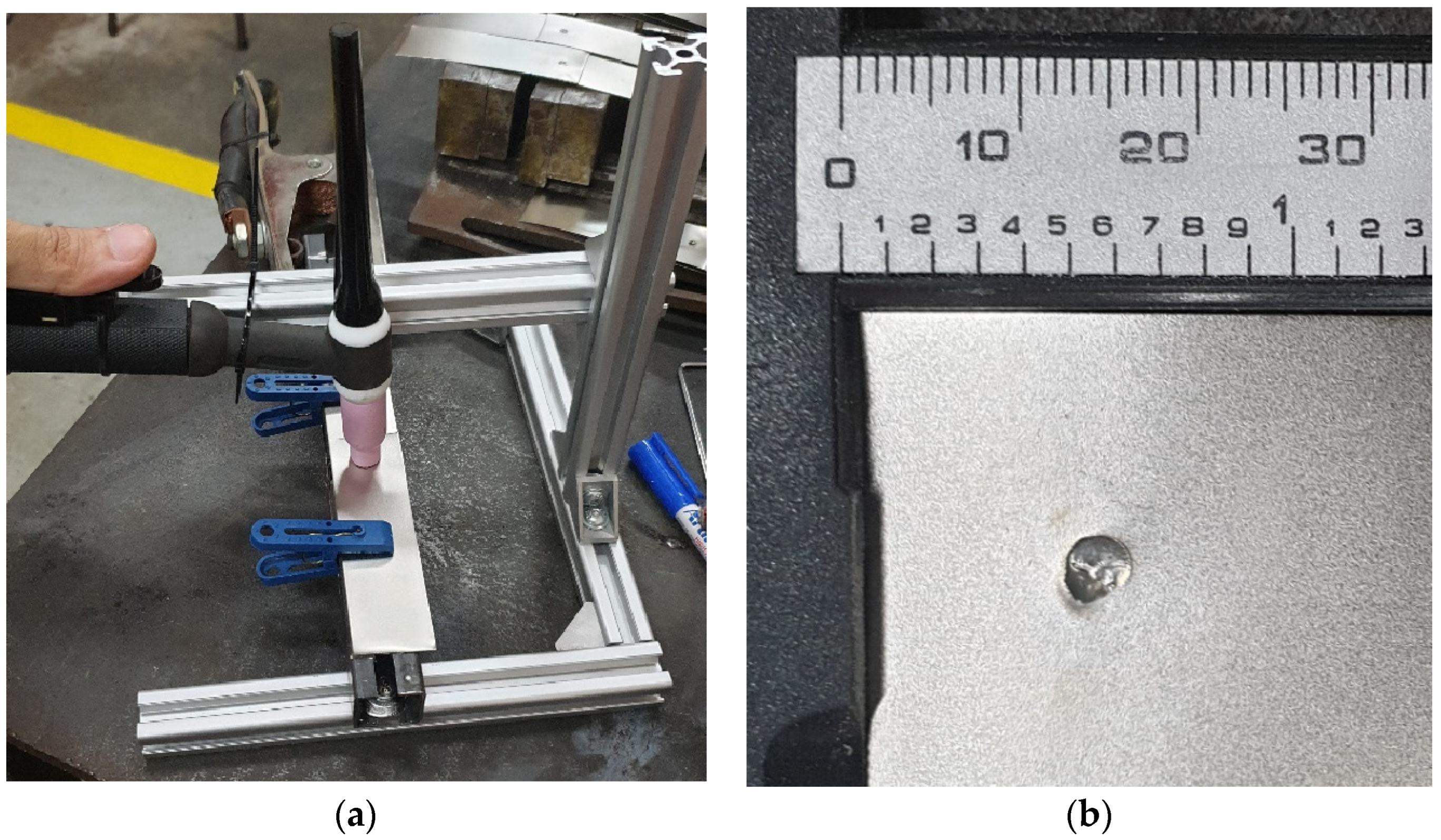
Figure 2 shows the jig setup for the test samples during the experiment and one of the welded test samples.
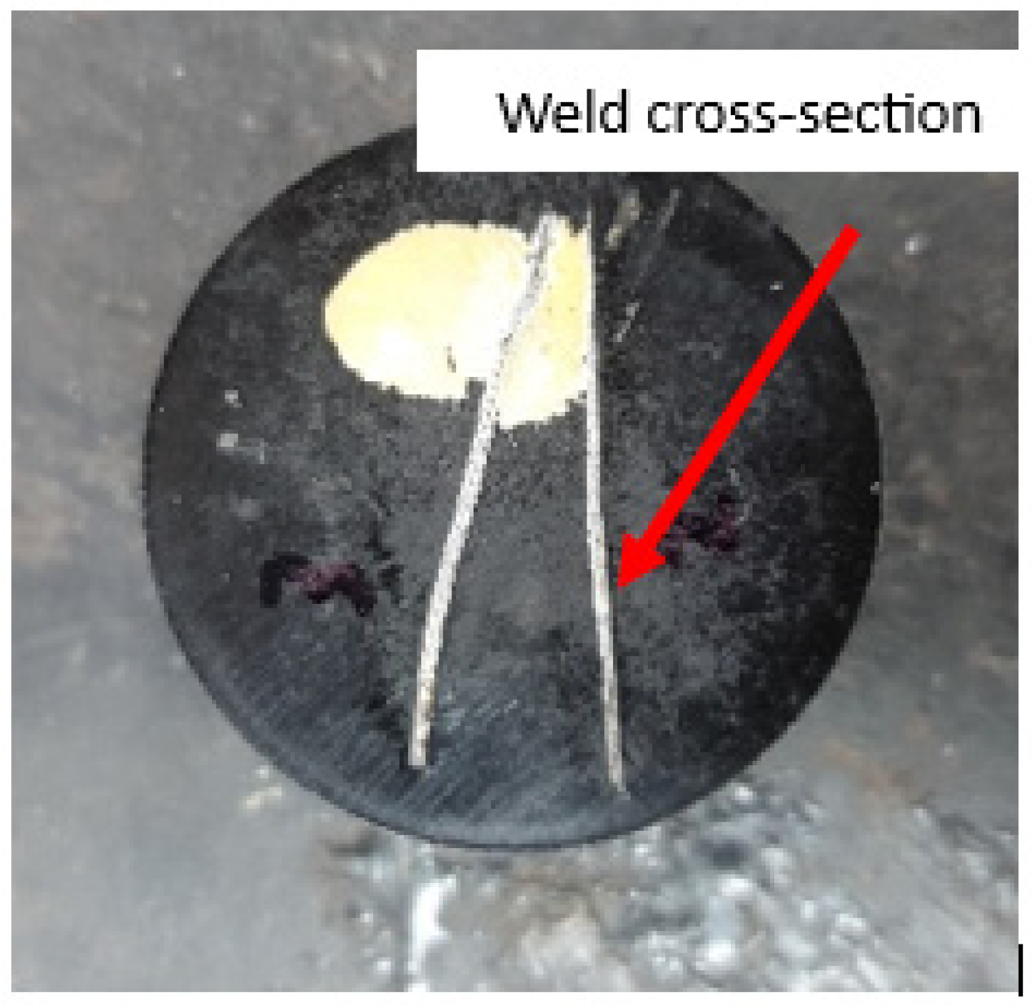
Following completion of the welding process, the test samples underwent characterization through microstructure analysis, mechanical testing and electrical resistance evaluation. For microstructure analysis, the specimens were observed under a scanning electron microscope (SEM). At this stage, the test samples were cut into 10 mm strips, where the cut was made on the cross-section of the weld. The test sample was then molded with molding material using an automatic mounting press to ease handling. Then, the test sample was wet-sanded to remove any scratches made during the cutting process. Subsequently, an etching process was employed, involving the application of nitric acid to eliminate any remaining residues.
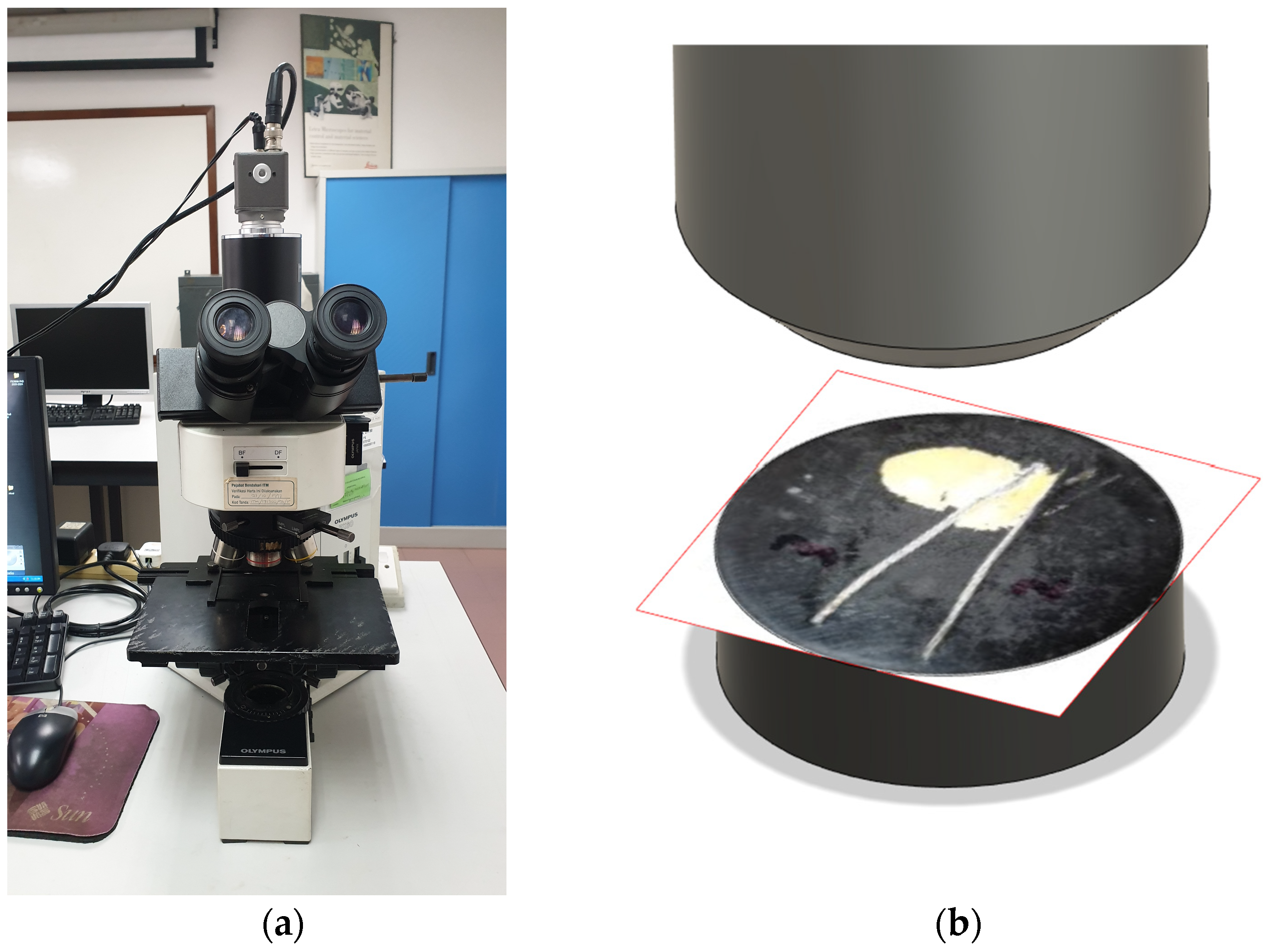
Figure 3 shows the molded test sample with annotations indicating the extraction points.
Figure 4 shows the SEM utilized to observe the test sample and the simulated position of the molded test sample under the SEM.
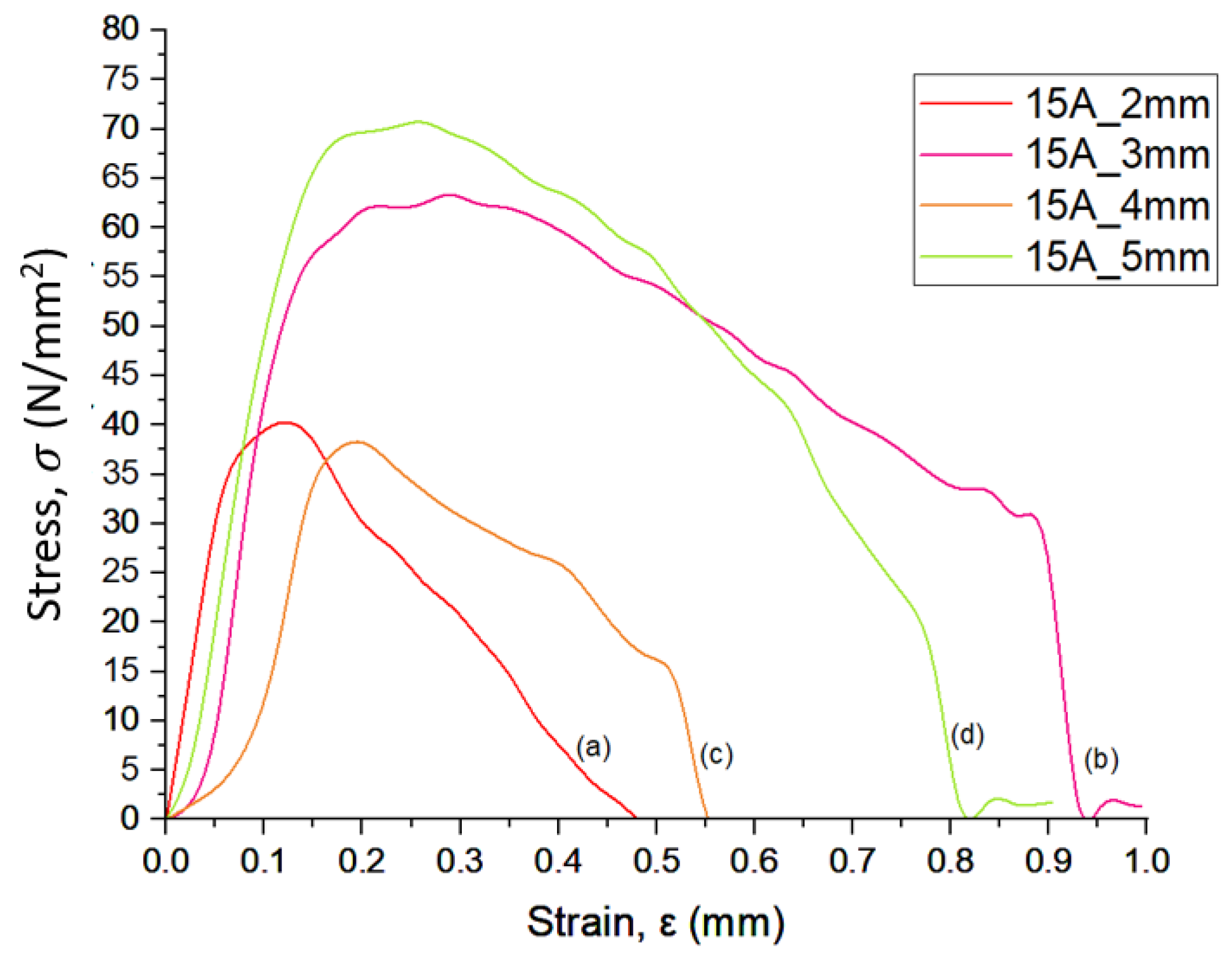
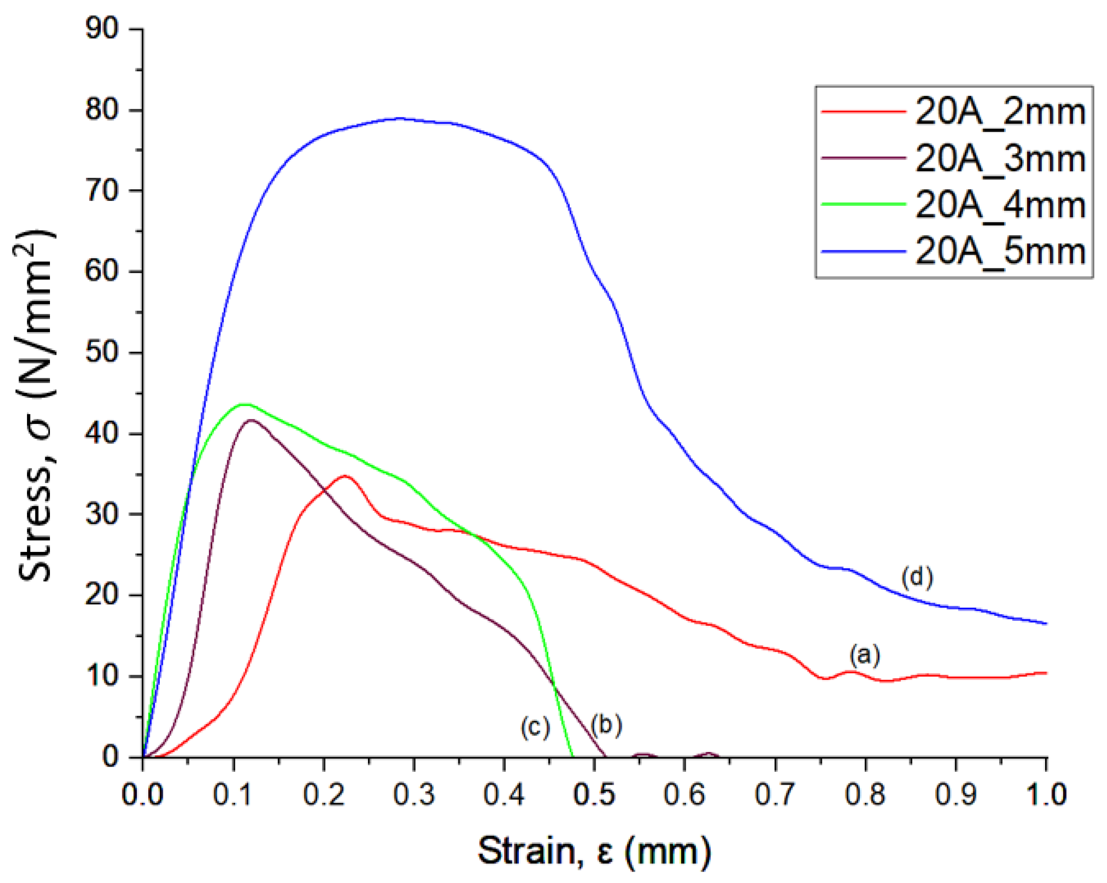
In terms of mechanical testing, the tensile test was performed using a Shimadzu Servopulser universal tensile testing machine. Tensile testing involves converting the force applied to the material into stress to observe and understand the material’s behavior under load. The relationship between force and stress is fundamental in material science and engineering, and the relevant formulas are shown below. The stress (
is given by Equation (1):
where σ is stress (Pa), F is applied force (N), and A is the cross-sectional area of the material in unit m
2. Meanwhile, strain (
) is shown in Equation (2) as follows:
where ϵ refers to strain, ∆L is the change in length, and L
0 is the original length in unit meter (m). Then, Young’s modulus, E (Pa) is defined by Equation (3):
From the relevant formulas, stress can be obtained from the stress induced in the tensile testing. The force is applied to the test sample uniaxially and gradually increases until the material deforms or fractures. The force is recorded at each increment. Then, the cross-sectional area of the test sample is measured, which in this case is 30 mm in width and 0.3 mm in thickness, resulting in a value of 9 mm
2 or 9 × 10
−6 m
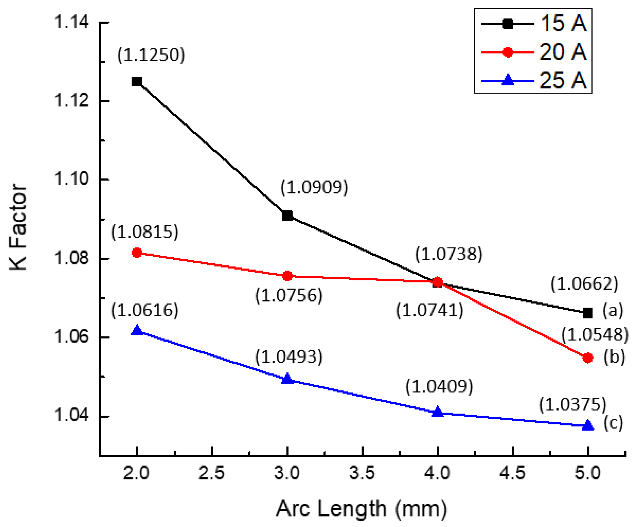
2. This is under the assumption that the test sample has uniform cross-section and is an isotropic material. The stress can then be calculated by using the stress formula. The stress and corresponding strain are recorded continuously and simultaneously to generate a stress–strain curve. This allows for insight into the test samples’ mechanical properties such as the yield strength, ultimate tensile strength and elastic modulus. Simultaneously, resistance analysis of the sheet was conducted using a multimeter. The recorded values were then utilized to calculate joint resistance using the K factor, Equation (4):
where R
st1&st2 refers to the resistance of weld. R
st1 denotes the resistance value of the first nickel-plated steel sheet, while R
st2 is the resistance value of second nickel-plated steel sheet. Both values are added and divided by 2 to get the average resistance of the nickel-plated steel. A K factor of 1 implies no joint resistance, and it indicates that the overlap zone has the same resistance as the parent metal. The designated sites for measuring the resistance of the spot weld are depicted in
Figure 5.
4. Conclusions
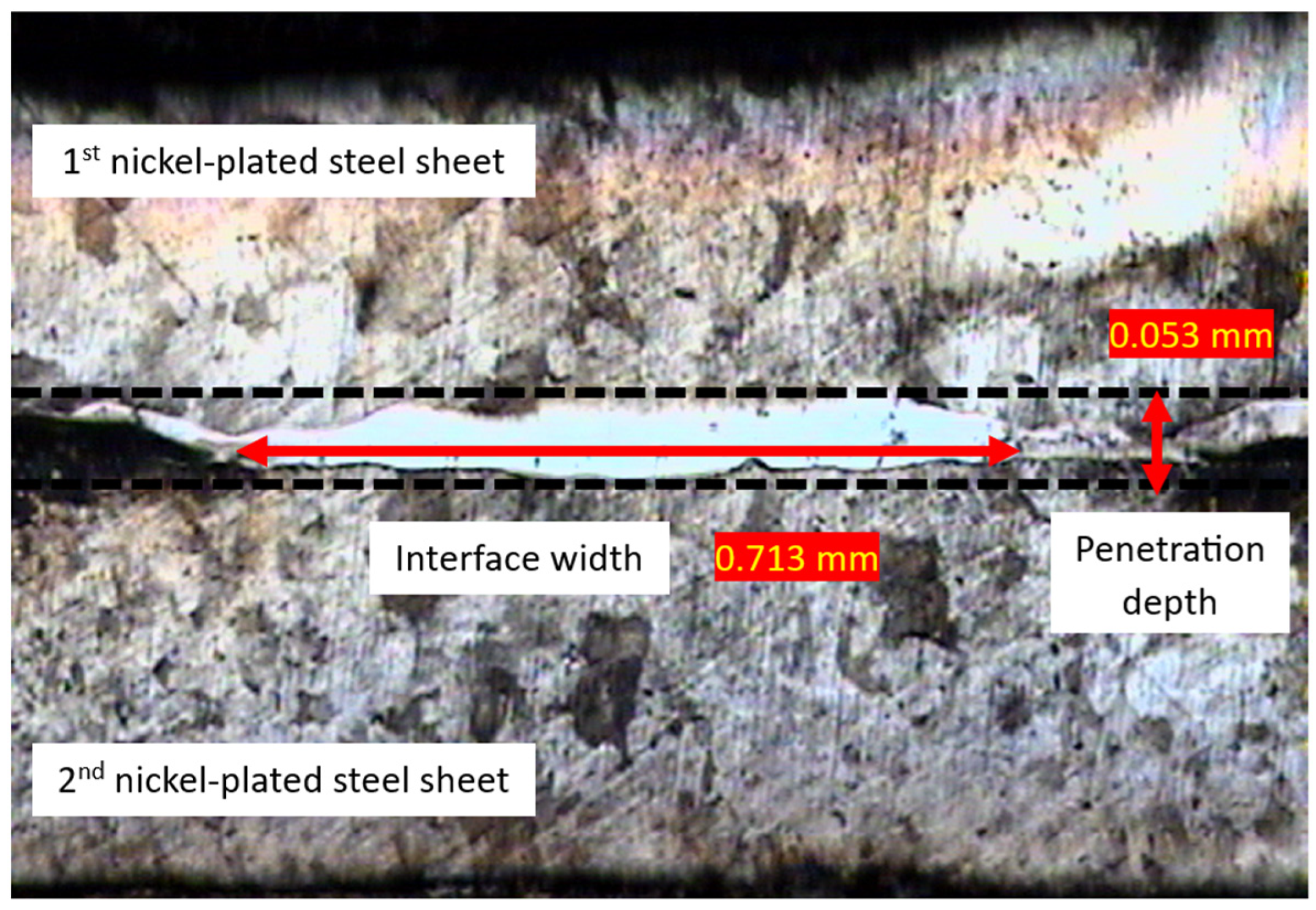
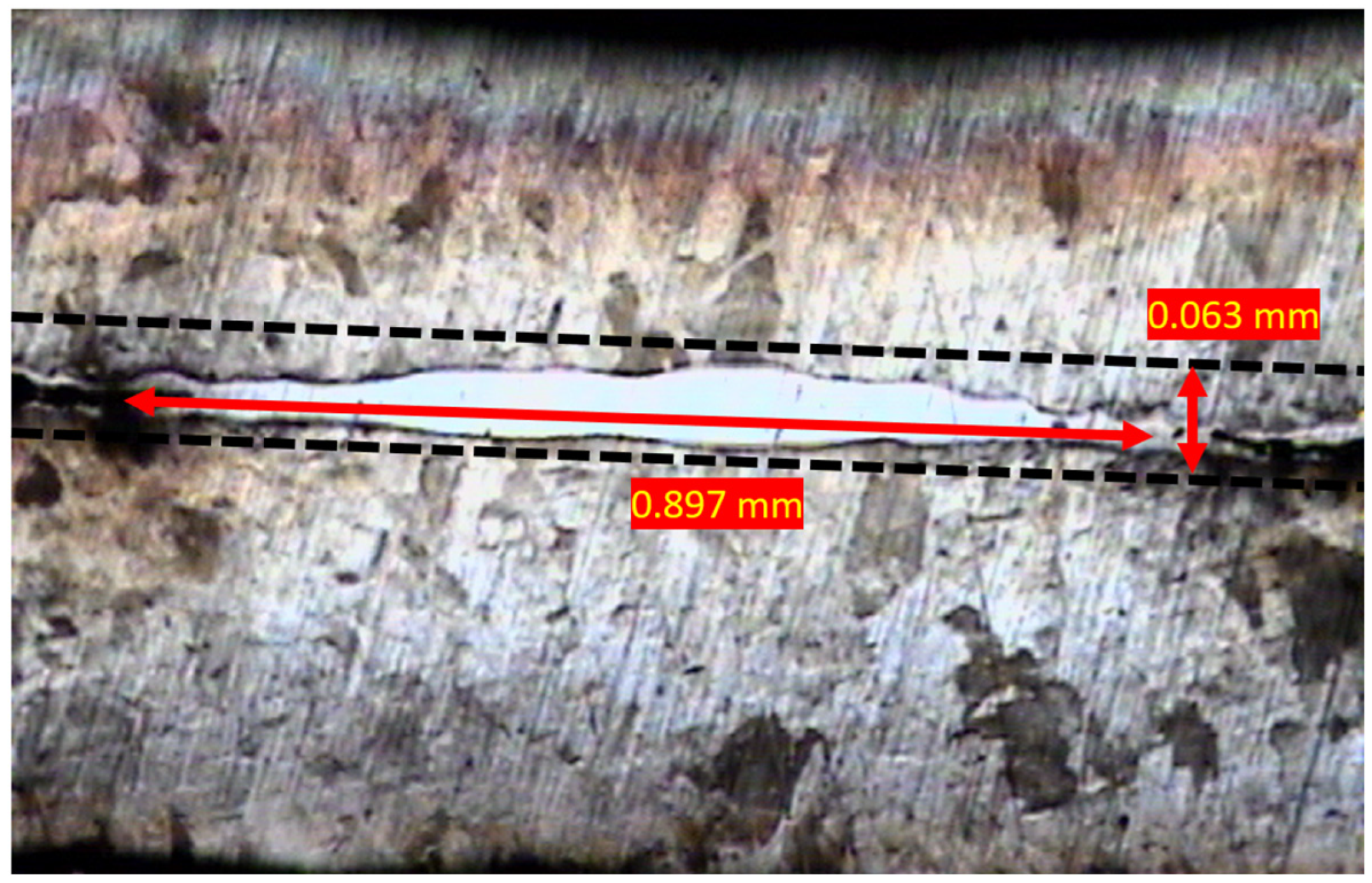
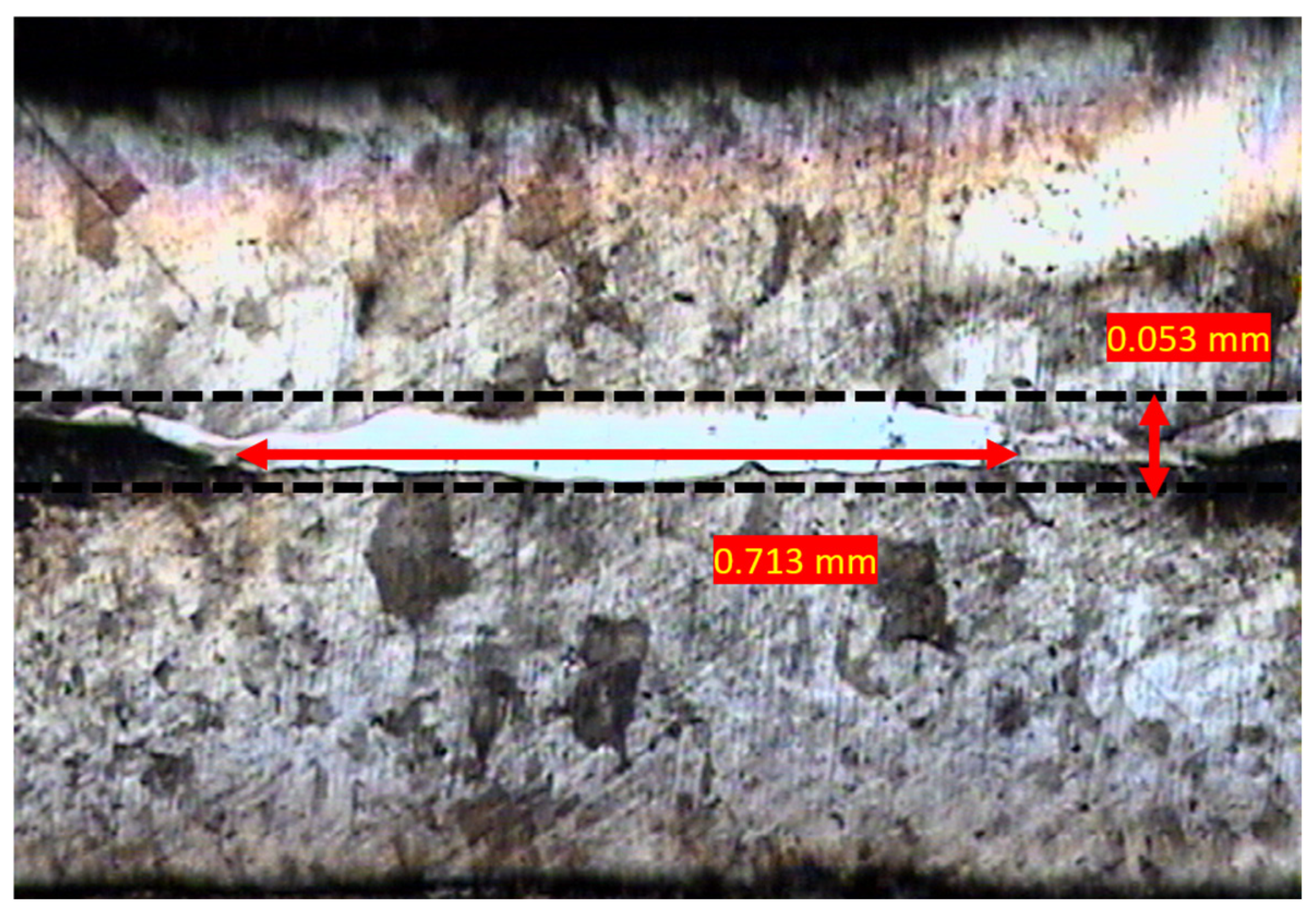
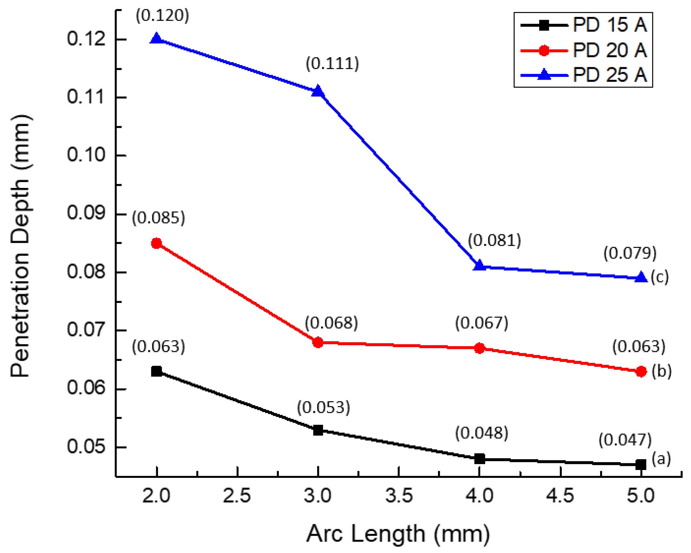
In summary, the investigation into micro-TIG welding on nickel-plated steel sheets underscored significant material impacts. Through a comprehensive exploration of various arc lengths and current modulations, the optimal performance was consistently observed at a 5 mm arc length with a 25 A current modulation. Microstructural analysis further revealed a notable 0.079 mm penetration depth and the widest interface width, contributing to a more extensive and shallower fusion zone at the filler metal and the base material interface. Mechanical testing corroborated these findings, with the welded joint exhibiting a maximum UTS of 90 N/mm2, a yield strength of 85 N/mm2, and the highest elastic modulus. These characteristics collectively assessed the strength, deformation behavior, and the overall reliability of the welded joint. The refined metallurgical bond resulting from these conditions fortified the weld’s ability to withstand applied loads and resist fracture. Moreover, the calculation of the lowest K factor at 1.0375 indicated reduced resistance across the specimen, translating to higher conductivity. This attribute particularly facilitates efficient high-current flow and is advantageous for battery joints. The conclusion of these outcomes positions the combination of a 5 mm arc length and a 25 A current modulation as the potential parameters for achieving optimal welded joints in nickel-plated steel sheets. The implications of these findings extend the realm of welding research, holding promise for diverse industries. The identified parameters could pave the way for the optimization of micro-TIG welding processes, especially beneficial in real-world applications and, specifically, for electric vehicles, particularly in enhancing the performance of battery packs.
The research on micro-TIG welding of nickel-plated steel sheets has several limitations, including its focus on a specific material, which may not be directly applicable to other materials such as aluminum or copper, and its restriction to micro-scale applications, not addressing the effectiveness for larger components. The study does not account for environmental factors like temperature fluctuations, humidity, and exposure to corrosive elements, nor does it replicate real-world operational stresses such as vibrations, thermal cycling, and mechanical impacts. The investigation is limited to specific current modulations and arc lengths due to limited time and research budget, potentially overlooking optimal parameters for different applications. Additionally, the microstructural analysis conducted may not cover all potential changes, necessitating advanced techniques like transmission electron microscopy (TEM) or X-ray diffraction for comprehensive insights. The research also lacks long-term fatigue and durability testing, essential for ensuring the reliability of welded joints over the battery pack’s lifespan. Future work should explore the application of micro-TIG welding to a broader range of materials, investigate its effectiveness for larger components, conduct environmental testing, expand the range of welding parameters, and utilize advanced microstructural analysis techniques. Long-term fatigue and durability studies are needed, along with comparative studies of micro-TIG welding against other advanced welding techniques. Developing automated systems and advanced process control algorithms can enhance precision and efficiency, while comprehensive cost–benefit analyses and integration studies with existing EV manufacturing processes can evaluate the economic feasibility and impact on production efficiency. Addressing these limitations and pursuing the suggested future work can expand and refine the research, potentially leading to broader applications and more robust solutions for the challenges faced in the EV industry.
