Abstract
This research investigates the correlation between polymer melt viscosity, tensile properties, and injection molding energy consumption for three grades of polypropylene: a virgin grade, a recycled grade, and a modified recycled grade. Cold runner and hot runner molds are considered. The experiments focus on characterizing the thermal and mechanical energy drawn by the injection molding machine during the cycle. The data collected from the experiments are used to calculate the embodied energy as a function of the polymer viscosity and processing conditions. The analysis of the relationship between polymer rheology and processing provided guidelines for the molded parts’ embodied energy and mechanical characteristics. These guidelines and estimation techniques will support sustainable design for manufacturing practices.
1. Introduction
1.1. Energy Consumption in Injection Molding
As the most widely used method of processing plastic [1], injection molding accounts for a massive amount of energy consumed yearly. Injection molding is used to efficiently manufacture complex geometries, making it a widely used manufacturing technology in many industries, ranging from consumer products and medical devices to aerospace and automotive applications. In the United States, the injection molding industry uses roughly 30 billion kWh of electricity annually. In China, the energy consumption is over 210 billion kWh [2]. Reducing energy in injection molding can have a significant economic and environmental impact due to this high usage level in today’s manufacturing landscape. These economic and environmental impacts are defined in the majority during the product design phase, hence the importance of understanding how energy is impacted by material selection and processing.
The measurement of the injection molding machine’s energy consumption allows the evaluation of the most significant drivers, allowing the design of efficient processes. The energy consumption during processing can be assessed per part as an embodied energy value, where the total energy used to produce a part is divided by the final part mass. Throughout the injection molding cycle, different machine, mold, material, and process parameters combine to define energy consumption. A recent study by Nguyen et al. emphasized the lack of reliable data for injection molding processes in life cycle analysis (LCA) [3]. Understanding each contribution requires an analysis of the significant hardware components.
1.2. Factors Affecting Energy Consumption
Different processing and design parameters have been evaluated for their effects on energy consumption in injection molding. The matrix is complex, based on product requirements, material selection, and equipment limitations. Compromises can arise between reducing energy consumption and promoting adequate mechanical properties. Research has been conducted on the factors affecting energy consumption while using virgin materials, but there is a lack of data supporting the conclusions for using recycled polymers. Table 1 displays the effects of key processing and design decisions on the energy consumption of molded parts as supported by literature.

Table 1.
Summary of factors affecting energy consumption in injection molding (↑ indicates increasing energy consumption, ↓ indicates decreasing energy consumption, - indicates the factor has no effects on energy consumption; number of arrows indicates the significance of the effects).
1.2.1. Processing Parameters
Barrel heaters consume a large percentage (approximately 50%) of the total energy in the injection molding process [4,5]. During the plastication phase, the polymer resin must be melted when a molten polymer shot is built. This is accomplished by the heater bands in the barrel and the shear heating of the rotating screw. The heater bands consume electrical energy to heat the barrel to the specified melt temperature, and lower temperatures require less energy [6,7]. Optimizing the barrel melt temperature determines a tradeoff between the part quality and energy consumption. Indeed, higher melt temperature leads to lower melt viscosity, thus improving the replication of the mold geometry. Thiriez et al. observed that the energy consumption increased by 15% for the average barrel temperature rise of 20 °C for the multiple resins investigated [7]. Tranter et al. focused on the effect of process parameters on the process energy consumption, including melt temperature and mold temperature. An optimal tradeoff between power consumption and part quality was determined through direct energy measuring of the equipment and mechanical testing on the molded parts [5].
Müller et al. studied the impact of cycle time and the changes in the electronic powers throughout the process stages to determine whether certain processing conditions improve the efficiency of the injection molding process [8]. Krantz et al. showed that different process control methods, including velocity-controlled and pressure-controlled cycles, can result in different part properties and energy [9,10]. The pressure-controlled method adjusts the screw injection velocity to maintain constant nozzle melt pressure, which provides better control of the melt viscosity [9,11,12,13]. This higher level of control during injection has been correlated to better part quality [14,15,16]. Additionally, adjusting the transfer position based on the cavity pressure characteristics during injection molding increases the uniformity of enhanced part qualities [17]. While there are approaches to closed-loop process control, and some are based on pressure, in-depth investigations of the effects on energy consumption have not been conducted. The effect of injection speed on the mechanical properties of molded samples has been studied, which can provide insight into how different control strategies impact the mechanical properties [18].
1.2.2. Mold Design and Machine Type
Different machines and mold types can require different amounts of energy during processing. In general, mold types can be characterized by the runner system designs. A cold runner system contains a runner channel through which the polymer melt flows before reaching the part cavity gate [19]. This runner is molded, cooled, and ejected with the part. A hot runner system has a heated runner system in which the polymer remains molten, and the runner system is not molded with the part. The hot runner system requires extra heating elements but reduces part waste by not molding the runner system for each shot. A cold runner mold does not require additional power, while a hot runner mold requires an additional temperature controller to heat the hot drop gates and internal heated runner system. However, the embodied energy of the scrap runner system molded by a cold runner mold is absorbed by the molded part, increasing the part’s embodied energy. Because of this, although the hot runner system requires higher energy consumption, the part embodied energy may be lower than the parts molded by a cold runner design. Material savings and product quality improvement have been established using hot runner systems [20]. Demirer et al. investigated how eliminating the sprue in hot runner systems can further reduce cycle time and processing conditions, decreasing energy consumption [21]. Kazmer et al. found that the mechanical properties between hot and cold runner molded samples exhibited minimal variation, and any losses in mechanical properties could be correlated with thermal degradation of the resin due to melting temperatures and residence times being too high [22].
The size of the mold has a significant effect on energy consumption. Indeed, a larger and heavier mold will require more energy to operate. Moreover, a larger mold is typically associated with larger volumes of polymer injected into the cavities, hence higher melting energy. When considering part and mold design, all parameters that increase the injection pressure should also be expected to increase the energy requirements.
Electric injection molding machines have been reported to consume less energy than hydraulic ones [23]. Indeed, electric servo motors only consume power while running (i.e., clamp open or close, ejection system actuation, screw rotation, etc.), unlike hydraulic pumps that run continuously through the molding cycle [2,24].
1.2.3. Material Selection
Besides design and processing parameters, the properties of the polymer material selected significantly affect the process energy consumption and mechanical properties of the molded products. The use of recycled polymers has increased in popularity recently as the focus on sustainability and plastic circularity in manufacturing has been promoted. The material energy of virgin vs. recycled resins significantly differs due to the processes used to produce the functioning resin. Virgin polymers are synthesized from raw materials and provide a clean product with controlled material properties. The extraction of raw materials for the polymerization of virgin polymers is the most environmentally taxing stage of polymer manufacturing [25]. This drastically increases the embodied energy for parts molded from virgin materials. Gao et al. found that with high-speed extrusion, the embodied energy of processing 100% recycled material was >15% lower than processing virgin material by eliminating the energy required to synthesize neat polypropylene from fossil resources [12].
Injection molding of virgin materials is well established and standardized through extensive use and research. However, the results and conclusions on virgin materials cannot be directly used for recycled materials due to the unique challenges of recycled resins. While many researchers have studied the effect of repeated mechanical recycling cycles on the decay of properties for injection-molded parts, limited data are reported for polymers obtained from municipal or industrial waste streams [26,27]. Using recycled polymers in processing incurs challenges due to the contamination of waste streams and polymer chain breakdown [28,29]. Recycled resins are sourced from waste streams, which introduce a variety of contaminants into the material.
In this research, a film-grade post-industrial polypropylene waste was used and investigated to explore its possible use for injection molding. Film waste streams are hard to collect and clean due to their high aspect ratios. Film waste is a complex mix of polymers of unknown composition and is usually contaminated by organic fractions, such as food remains, and non-polymer fractions, such as paper [30]. The waste streams must be cleaned, sorted, and reprocessed into usable resin, which causes significant changes in material properties due to the mechanical and thermal degradation of the polymer chains during recycling. These challenges are often observed as rheological inconsistencies during injection molding, resulting in processing difficulties and lower mechanical properties in the molded part [31]. Incarnato et al. concluded that increased recycling operations on polymer films significantly reduced the elongation at break [32].
The layout of a design and the part wall thickness determine a majority of a product’s environmental and economic efficiency, and the ability to mold more complex designs with thinner wall thicknesses is directly related to polymer melt viscosity. Recycled materials exhibit lower viscosities, making them potentially better for molding thin-walled parts. However, a tradeoff exists for recycled materials because although the embodied energy and viscosity are lower than virgin materials, they also exhibit reduced material properties in most contexts. There is a lack of existing research on the effect of parameters and molding decisions to optimize the use of molded recycled materials, so investigating this topic will provide a more comprehensive understanding of recycled resin manufacturing, allowing for its increased usage.
This research investigates the effect of polypropylene molecular weight and melt rheology on energy consumption in injection molding. Three grades of PP with different recycling histories are considered. The embodied energy for the molded parts is examined by considering the material synthesis, recycling, and injection molding.
2. Materials and Methods
2.1. Polymer Selection and Characterization
Three grades of polypropylene were selected for this work to study the effect of their melt rheology on processing. The first resin (PP) was virgin Borealis polypropylene (BB125MO 19C24AB3, Borealis, Houston, TX, USA). The virgin material is an extrusion or blow molding grade heterophasic PP copolymer. The material was selected to compare with the recycled film waste. It should be noted that it was impossible to identify the exact commercial grade used for the film waste; hence, an assumption was made when selecting the benchmark virgin grade. The second resin (RPP) was obtained from a 100% post-industrial BOPP film waste stream (Green Isoplen X201R, SER North America LLC, Anderson, IN, USA). This material was pretreated, compounded, and pelletized by the supplier. The second resin was processed as received from the recycling facility. The third resin (MRPP) was a modified version of the RPP in which the molecular weight was further reduced through high-speed extrusion (KZW15TW-45/60MG-NH-4400-UM, Technovel, Gastonia, NC, USA) at UMass Lowell. This was performed by extruding the RPP at 4000 rpm with the temperature profile defined in Table 2.

Table 2.
Temperature profile set for high-speed extrusion of the RPP.
Thermal Gravimetric Analysis (TGA, TGA 2 SF, Mettler Toledo, Greifensee, Switzerland) was performed from 0 °C to 600 °C with a ramp rate of 20 °C/min to gather polymer degradation data. Differential Scanning Calorimetry (DSC, DSC 3+, Mettler Toledo, Greifensee, Switzerland) was performed between 0 °C and 250 °C with a heating rate of 10 °C/min and a cooling rate of 5 °C/min to assess the melting behavior and capacity for crystallization of the polymers.
The melt flow rate was obtained on the Dynisco Laboratory Melt Indexer (Series 5000, Dynisco, Franklin, MA, USA) following ASTM D1238-10 [33] at 230 °C. Density testing was conducted on the density tester (MS303TS/00, Mettler Toledo, Greifensee, Switzerland) following ASTM D792 [34]. A rotational rheometer (ARES-G2, TA Instruments, Newark, DE, USA) with 25 mm stainless steel parallel plates was used to characterize the rheological properties. Disc-shaped specimens were prepared using an Xplore injection molding machine (IM 12, Xplore, Sittard, the Netherlands). Strain sweeps were conducted at 170 °C to identify a strain in the linear viscoelastic region for frequency sweeps. Frequency sweeps from 0.01 Hz to 100 Hz were performed at 170 °C with a strain percentage between 2% and 5%. The lowest frequency data point from each curve was approximated as the zero-shear viscosity, and data points at ~30Hz (200 rad/s) were considered high-shear-rate viscosity, which represented the viscosity of the material in the injection molding process.
The differences between the three materials were investigated by focusing on their chemical compositions, thermal properties, and rheology. The properties of the resins are discussed in this section before their processing behavior and correlations with energy are analyzed. Table 3 summarizes the critical material properties of the three resins investigated. Figure 1 presents the FTIR spectrum, Figure 2 presents the melting behaviors, and Figure 3 presents the viscosity change with the shear rate of the resins.

Table 3.
Characterized material properties of PP, RPP, MRPP.
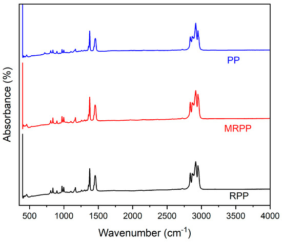
Figure 1.
FTIR spectrum of PP, RPP, and MRPP.
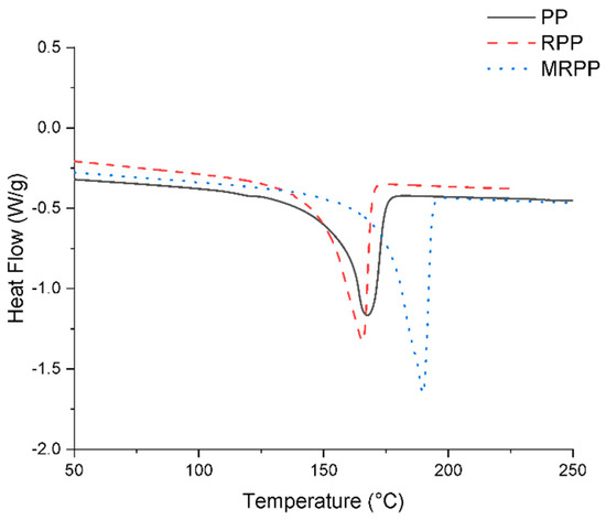
Figure 2.
Melting curve of PP, RPP, and MRPP during DSC scans. The heating rates are 10 °C/min.
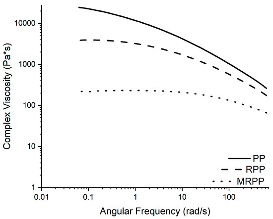
Figure 3.
Complex viscosity curves for PP, RPP, and MRPP.
2.2. Injection Molding Setup
The injection molding machine used for these experiments was a 130-ton machine (Roboshot α-S130iB, Milacron-FANUC, Batavia, OH, USA) with a 40 mm screw diameter. A cold runner and a hot runner mold were used in the injection molding experiments. The cold runner mold was a single cavity two-plate cold runner ASTM type I tensile bar mold, with three pressure sensors, two in the runner and one in the cavity. The hot runner mold used for the experiments was a dual cavity valve gated hot runner mold, which produced two ASTM type I tensile bars in each shot. The sensor locations of the cavity pressure sensors are displayed in Figure 4, with the cold runner cavity shown in Figure 4a and one of the two identical hot runner cavities shown in Figure 4b.
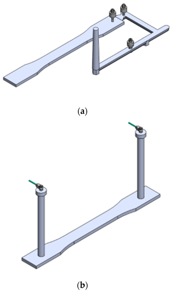
Figure 4.
Cavity pressure sensor locations: (a) cold runner, (b) hot runner.
The mold sensors were connected to a charge amplifier (Type 5073, Kistler, Winterthur, Switzerland). The sensor data were acquired through a data acquisition system implemented on the injection molding system with a frequency of 1000 Hz.
The temperature of the hot runner mold was controlled using a multi-zone temperature control unit (MT-12-12, Mold-Masters, Halton Hills, ON, Canada). Two of the six available heating zones on the temperature controller were used to regulate the temperatures of the individual hot runner systems and hot drop gates. These zones were set to the melt temperature of the current experimental trial and were given 30 min to thermally stabilize after being turned on. When the melt temperature was changed, an additional 30 min was given for thermal stabilization.
The injection molding process was controlled using velocity-controlled and pressure-controlled cycles. The velocity-controlled cycle used the conventional method and the standard logic provided by the Milacron-FANUC injection molding machine. The general processing conditions were determined from short-shot experiments (i.e., 95% and 80% of the fill cavity volume). The velocity-controlled process used packing pressure levels set to 80% and 60% of the injection peak. The pressure-controlled cycle used an instrumented nozzle with an integrated pressure sensor and control unit technology provided by iMFLUX, Inc (West Chester Township, OH, USA). This technology includes a pressure transducer implemented in the nozzle of the injection unit between the plastication screw and the sprue. The iMFLUX control unit overrides the conventional velocity-controlled cycle logic and applies a pressure-controlled cycle instead. For the pressure-controlled cycle, a consistent nozzle pressure value is maintained by controlling the screw velocity with a closed-loop logic. Figure 5 displays a general nozzle pressure and screw velocity curve for both the pressure-controlled and velocity-controlled cycles.
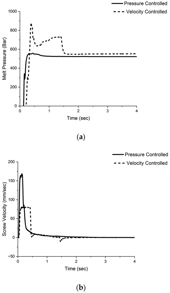
Figure 5.
(a) Nozzle pressure and (b) screw velocity for pressure-controlled and velocity-controlled cycles.
2.3. Experimental Approach
A two-level, four-factor full-factorial design of experiment (DOE) was designed to investigate correlations between mechanical properties and embodied energy for the different PP grades selected in Section 2.1. Table 4 shows the DOE plan and the levels selected for the experiments. Factors were selected considering their effects on energy consumption and melt viscosity. These factors were the screw recovery speed, barrel melt temperature, mold type, and process control method. The melt temperature and screw recovery speed levels were chosen by designing an optimal injection molding process by following the standard short-shot method and by selecting levels above and below the optimal condition while remaining in the processing window of the resin. The levels for mold type and process control method were defined by the two methods investigated.

Table 4.
DOE plan defined for the experiments.
The molding machine was operated in fully automatic mode with other parameters held constant to the values shown in Table 5. To allow process stabilization at process start-up, 60 automatic molding cycles were run, and the resulting moldings were discarded. To guarantee the stability of the molding process and the data acquisition setup, 20 molding cycles were discarded for each DOE run before collecting the first part. For each of the 16 DOE runs, 10 parts were collected for a total of 160. Then, the DOE was repeated for each of the three materials for a total of 480 parts collected for characterization.

Table 5.
Injection molding processing parameters kept constant during the DOE experiments.
The DOE plan was analyzed by considering different response variables, including tensile properties and energy consumption. Tensile data were gathered at room temperature using a Universal Testing System (Instron 5966, Norwood, MA, USA) following ASTM D638 [39] at a 50 mm/min strain rate. Five samples were tested from each DOE run. The modulus, yield stress, and ultimate elongation were then calculated from the stress–strain curves.
2.4. Energy Consumption Monitoring
The energy consumption during the injection molding process was monitored for the machine and the auxiliaries. Figure 6 reports the energy components that were monitored using multiple power meters.
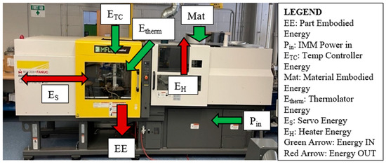
Figure 6.
Injection molding energy pathway.
The energy consumption of the barrel heater bands and servo motor per shot was monitored using a power meter in the molding machine. The machine’s energy consumption was divided into 3 sections: heater energy, servo motor energy, and other energy (e.g., control panel, sensor systems, and internal auxiliary functions).
The energy consumption of the external auxiliary equipment, consisting of the thermolator and hot runner temperature controller, was measured using an external power energy logger (PEL 103, AEMC Instruments, Dover, NH, USA).
Considering the energy data monitored during the process, the total injection molding energy (EIM) per shot was calculated as follows:
where:
EH is the energy consumption of the heater bands;
ES is the energy consumption of the servo motor;
EO is the energy consumption of other machine components;
Etherm is the energy consumption of the thermolator;
ETC is the energy consumption of the temperature controller (only for hot runner mold).
The total injection molding energy per shot in kWh was then converted to MJ and divided by the mass of each part in kg to obtain the injection molding embodied energy (EEIM). For the hot runner data, the EIM Total was divided by the part mass of both parts produced by a single shot to provide the embodied energy per part:
For the cold runner data, the EIM Total was divided by the mass of the de-gated part, so the molded part absorbed the embodied energy of the runner system. For the cold runner mold, the volume of the feed system (runner and gate) was 75% of the cavity volume.
The analysis of the energy involved in the manufacturing of the different PP grades was further investigated by calculating the total embodied energy:
where EEmaterial is the energy required to synthesize the polymer, EErecycling is the energy needed to recycle the material, EETSE is the energy required for modification, and EEIM is the injection molding energy (cf. Equation (2)).
The EEmaterial for the PP was obtained from literature data taken from an Ashby plot [40]. The average PP embodied energy was estimated at 79 MJ/kg. For the RPP and MRPP, the EEmaterial was zero since it was obtained from waste materials. Conversely, the EErecycling was considered only for the RPP and MRPP. An average value of 0.24 MJ/kg was calculated from energy data monitored on the extruder during recycling by the supplier. It should be noted that this does not include the energy required for shredding and densification of the film waste before extrusion and pelletization.
A digital amperage meter was used to monitor the current drawn during the high-speed extrusion modification of the RPP to MRPP. The amperage was recorded every 15 min during processing. The twin-screw extrusion (TSE) energy consumption for the modification process (PTSE) for the three-phase TSE was obtained using Watt’s law:
where:
p.f. is a power factor (assumed at 1);
Aavg is the average amperage calculated from the experimentally recorded values;
V is the voltage (i.e., 180 V) used to power the extruder;
The specified mechanical energy (SME) is then calculated as follows.
where Q is the feed rate in kg/h The embodied energy for the TSE modification process is then calculated as follows:
3. Results and Discussion
3.1. Statistical Analysis of Energy Consumption
A factorial regression was conducted on the energy consumption data collected to understand the correlations between processing and design parameters on the injection molding energy consumption. The analysis separates the different energy consumption components, focusing on the servo motors and heaters.
3.1.1. Servo Motor Energy Consumption
Each DOE factor had a statistically significant effect on servo energy consumption. The melt viscosity of all the resins will be lower at the higher melt temperature set point (cf. Figure 7). With lower viscosity, the servo motor will be able to rotate the screw with less resistance and will require less energy to maintain the screw speed set point. The two control methods require different energy consumptions from the servo because the velocity-controlled cycle requires more energy during the filling stage and less during the packing stage. The pressure-controlled cycle requires more consistent energy throughout the cycle. The higher screw speed will require more energy from the servo than the lower screw speed because more energy is needed to rotate the screw at a higher speed. The hot runner mold will require more servo energy because it has a larger shot size (molding two parts) and must generate a larger molten shot during each cycle.
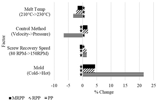
Figure 7.
Percent change in servo energy consumption from each factor for PP, RPP, MRPP (stars indicate significant factors).
The percent change from each factor was the highest on the PP. The difference in flow properties and molding behaviors are more drastic with higher molecular weight. For example, the difference in behavior between the two melt temperatures is more extreme for the PP because the large molecular weight chains act significantly different at the two temperatures. With lower molecular weight species, the difference in behavior at the two melt temperatures is less distinct. Due to the PP having the highest molecular weight of the three materials, the changes observed by altering the factors investigated had the most considerable effect on melt behavior, creating a more significant distinction between the servo motor energy values.
3.1.2. Heaters Energy Consumption
Melt temperature is the only factor that significantly affected heater energy consumption (cf. Figure 8). At a higher temperature set point, the barrel heater bands must draw more energy to reach the set value. Again, a higher percentage change in heater energy consumption is observed for the PP. This is a function of molecular weight, with RPP having the second-highest percentage change and MRPP having the lowest. Because MRPP has the lowest molecular weight chains, the difference in melt behavior is the smallest between the two melt temperature set points. The opposite is true for the PP, which we assume possesses the highest molecular weight chains as suggested by the high zero-shear viscosity. The temperature set point is the only factor directly related to the heater energy. Although the screw speed is a determinant of the shear heating of the resin in the injection unit barrel, its effect was found to be statistically insignificant on the energy consumed by the heater bands.
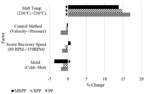
Figure 8.
Percent change in heater energy consumption from each factor for PP, RPP, MRPP (stars indicate significant factors).
3.2. Embodied Energy
The embodied energy of injection-molded parts is a measure of the energy consumption during the processing stages divided by the mass of the final part. First, we will consider the embodied energy from the injection molding process to evaluate the effect of material viscosity. Then, we will consider the embodied energy from all the process stages to assess the impact of using virgin, recycled, and modified materials.
3.2.1. Embodied Energy from Injection Molding
Considering the embodied energy solely from the injection molding process (cf. Equation (2)), the effect of material molecular weight and the resulting rheology on embodied energy during injection molding can be evaluated. The mold type and resin molecular weight affect the energy embodied in the molded parts from the injection molding process (cf. Figure 9).
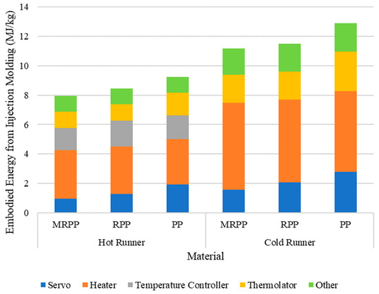
Figure 9.
Effect of material and mold type on the embodied energy from the injection molding process.
The embodied energy increases with higher molecular weight resins, with the virgin resin having the highest embodied energy of 9.25 MJ/kg on the hot runner and 12.88 MJ/kg on the cold runner. This is due to the increased energy the machine must consume to heat and process larger macromolecules. The embodied energy of the samples molded on the hot runner system is lower than that of the cold runner system due to the increased embodied energy of the cold runner parts from the additional molding of the runner system. Although the embodied energy of the hot runner parts includes an additional amount from the temperature controller energy, the embodied energy is still lower than that of the cold runner parts. The embodied energy of the MRPP was 7.93 MJ/kg on the hot runner and 11.17 MJ/kg on the cold runner, both of which are lower than that of the RPP with values of 8.46 MJ/kg on the hot runner and 11.48 MJ/kg on the cold runner. Again, this is due to the lower-molecular-weight species requiring less energy than the machine must consume during processing.
3.2.2. Total Embodied Energy
By considering the embodied energy from all the processing stages, the polymer resin goes through to reach its final molded state, as defined by Equation (3), and the effect of the resin production, recycling, modification, and injection molding processes on the total embodied energy of the parts can be evaluated.
The total embodied energy of the PP is much higher than the embodied energies of the RPP and MRPP (cf. Figure 10). This is due to the embodied material energy that results from the refinement and production of virgin resin. The modification process embodied a large amount of energy into the MRPP parts, increasing each part’s cost and environmental impact, making its embodied energy values higher than the RPP’s. It is still seen that the parts molded by the hot runner system had lower embodied energies due to the higher energy required to mold and scrap the cold runner system. The recycled and modified resins had lower embodied energy than the virgin resin due to the lower-molecular-weight polymer chains requiring less energy. This is an interesting result because although the recycled and modified resins must undergo a recycling extrusion process that introduces more energy into each part, they still have lower embodied energy than the virgin resin due to the addition of the resin production process.
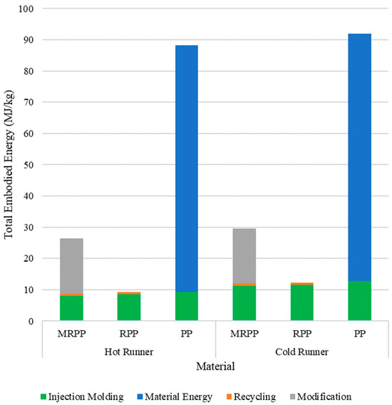
Figure 10.
Effect of material and mold type on the total embodied energy.
3.3. Tensile Properties
An analysis of variation (ANOVA) was conducted on the tensile data collected to understand the correlations between processing and design parameters on the molded part tensile properties. Table 6 displays the most critical determinant (XCritic) and the variance homogeneity (FMax) on the mechanical properties of each resin investigated. Figure 11 shows an example of the tensile behaviors for PP, RPP, and MRPP.

Table 6.
Summary of the ANOVA results for the different response variables for PP, RPP, MRPP.
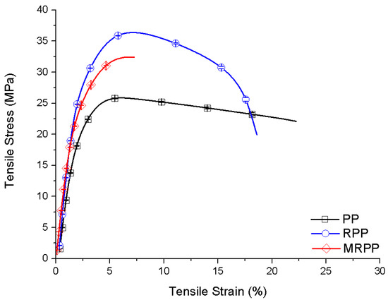
Figure 11.
Cold runner tensile curves for PP, RPP, and MRPP.
The melt temperature is the only significant effect on the yield stress for all three materials investigated (cf. Figure 12). The yield stress decreases with increased processing temperature. This behavior is due to the complex skin–core morphology common to injection-molded polypropylene [41,42]. The thickness of the oriented skin layer is inversely proportional to the polymer melt temperature because, at lower melt temperatures, the resin can develop a thicker skin layer due to the polymer melt being closer to its transition temperature [43]. Because the oriented skin layer is thicker for the samples produced at the lower melt temperature, the yield stress is higher because the increased degree of orientation in the skin layer provides more opportunity for higher intermolecular bonding and crystallization.
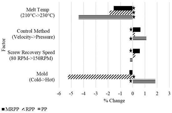
Figure 12.
Percent change in yield stress from each factor for PP, RPP, MRPP (stars indicate significant factors).
Figure 13 shows two samples of each material after tensile testing, one molded at the low and one at the high temperature, with all other processing factors kept constant.
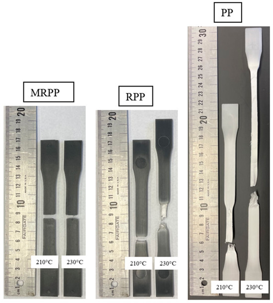
Figure 13.
Post-tensile-tested samples at melt temperatures 210 °C and 230 °C.
This image illustrates the presence of the different skin–core morphologies between samples molded at each of the temperature conditions. The higher temperature sample has evident delamination of a thin skin layer and much higher PP elongation. The lower temperature sample has almost no delamination of its thicker skin layer and displays a much lower elongation for the PP. This shows that a thicker, highly oriented skin layer is present in the parts molded at the lower temperature condition, providing higher yield stress values. The same trends occurred for the RPP and MRPP, but the delamination was less pronounced and was not as clearly observed.
The process control method significantly affected the yield stress for only the PP and MRPP. Still, the trend that the pressure-controlled cycle provides higher yield stresses is observed for all three materials. This trend is due to the pressure-controlled cycle providing constant packing of the polymer molecules during filling because the pressure is kept fixed as the part fills, whereas the pressure spikes during filling and then evens out during packing in the velocity-controlled cycle. This distinction between control strategies provides the pressure-controlled parts with higher macromolecular orientation, resulting in the sample’s higher yield stress [11].
Both the mold design and the screw recovery speed did not have a consistent significant effect on the yield stress of the molded parts. The mold design and screw speed do not have a significant impact on the filling of the part, so these factors did not have a uniform effect on the yield stress as they were changed.
3.4. Regression Modeling for Embodied Energy
Regression modeling was conducted on the data to provide guidelines to predict injection molding embodied energy and yield stress values as a function of different viscosity parameters. Specifically, the material was introduced in the DOE as a factor using the zero-shear viscosity, viscosity at 200 1/s (i.e., average shear rate during molding), and the melt flow rate. The DOE plan (cf. Table 7) was designed also to include the mold type and melt temperature. The parameters that were previously considered as not significant (i.e., screw recovery speed and process control method) were here excluded. The DOE plan was analyzed using the following regression model:
where C is the model intercept, A, B are coefficients, x is the selected material property, and y is the melt temperature. The model does not include the mold type, which was considered a categorical value in the DOE, yielding two regression models. Also, no interaction was included in the model since preliminary analysis indicated they were not statistically significant.

Table 7.
Regression DOE plan.
The fitted coefficients of determination (i.e., R2) are reported in Table 8 and Table 9 to assess the causality of each correlation for the cold runner and hot runner molds, respectively.

Table 8.
Cold runner regression equation R2 values (%).

Table 9.
Hot runner regression equation R2 values (%).
The regression data show that different parameters can be used to effectively predict the injection molding embodied energy of the molded parts. The molecular weight and shear viscosity factors were better for predicting the embodied energy of the hot runner parts than the cold runner parts. The in-mold viscosity values calculated from the cavity pressure sensor data show that the viscosity values were higher on average during molding with the hot runner mold. These higher values are closer to the rheological values used in the regression DOE, increasing the accuracy of the prediction models. The MFR is the worst predictor for the MRPP since the measured value was characterized by higher variation and less consistency.
The zero-shear viscosity is the best predictor for yield stress for both mold types. Worse predictions were observed when considering the viscosity at a higher shear rate due to approaching the upper limit of the parallel plate rheometer test. Overall, the R2 values are lower for the yield stress prediction equations than for the embodied energy predictions. Indeed, the effects of processing on morphology and its correlation with tensile strength are not considered by the material property factors used for the regression.
The model coefficients are plotted in Figure 14 and Figure 15, normalized by the mean of the data for the specific data set. From the analysis of the EEIM models, it can be observed that the material property factor and melt temperature are always significant for the hot runner and cold runner molds. However, the model intercept is only significant for the hot runner data sets. From the analysis of the coefficients for both EEIM and yield stress, it can be observed that B (i.e., melt temperature dependency) is always the same as expected since all models use the same data set but different values for the material property factor (x). The material property factor dependency (coefficient A) was consistent except for the high-shear viscosity.
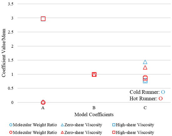
Figure 14.
Embodied energy from injection molding regression-equation-normalized coefficients for cold runner and hot runner molds.
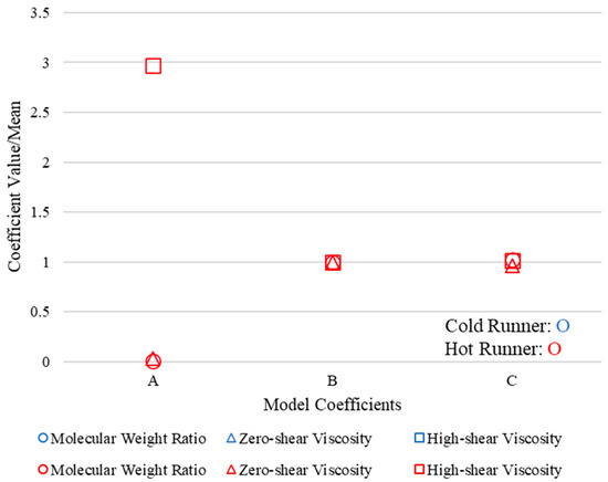
Figure 15.
Yield stress regression-equation-normalized coefficients for cold runner and hot runner molds.
Contour plots are reported in Figure 16 to analyze the relationship between melt temperature and material property factors in the DOE. From the plots, it can be observed that, for the design of the experiment defined in this work, the cold runner mold leads to consistently higher EEIM. Moreover, when using a hot runner, better melt stability is achieved, as demonstrated by the less evident bending of the surface plot along the melt temperature axis. In other words, using lower viscosity and temperature minimizes EEIM in the cold runner mold. In contrast, the optimum values of the hot runner mold are independent of the melt temperature.
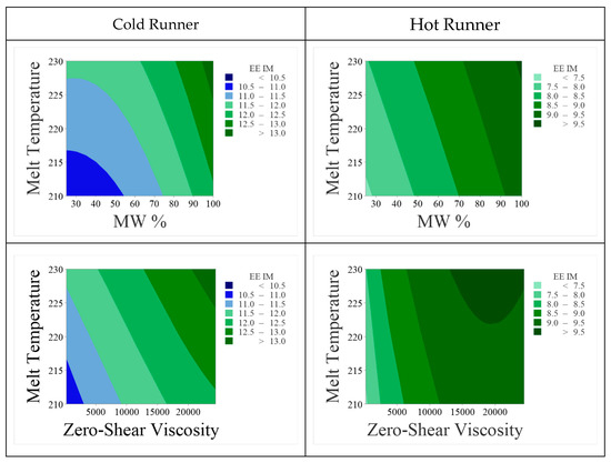
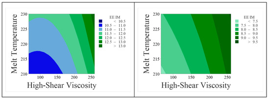
Figure 16.
Contour plots for the effect of the interaction between melt temperature and material property factors on the injection molding embodied energy.
4. Conclusions
This work investigated the effect of polymer molecular weight and rheological properties on the embodied energy and the mechanical properties of injection-molded parts. Conducting this research on three grades of polypropylene with different molecular weights allowed the evaluation of the resulting mechanical properties from different processing parameters, designs, and control strategies. By considering the material production stage the virgin material experienced, additional processing stages that the recycled and modified resins underwent, as well as the final injection molding stage that all three materials experienced, the total embodied energy of the molded parts made from each material could be appraised.
Lower heater energy consumption and embodied energy obtained when processing at lower temperatures for all three materials suggest the processing decision to mold polypropylene at lower temperature conditions. Though the energy consumption on the servo motors decreased by 2% to 4% among all three materials when increasing the barrel temperature from 210 °C to 230 °C due to reduced viscosity, the heater energy consumption increased by 14% to 17%. A lower barrel temperature of 210 °C maintained the tensile properties of the molded part as compared to parts molded at 230 °C. The barrel melt temperature set point was statistically significant on the mechanical properties. However, the change in yield stress was less than 4.5%.
The hot runner system avoids the manufacturing and discarding of the runner as compared to cold runner systems, which results in lower embodied energies in the molded parts. Though using hot runner systems requires an additional 1.5 KJ/kg embodied energy on the products, it also generates less waste in the runner and sprue and results in a 15–20% decrease in embodied energy for the molding process. However, when using hot runner systems, there is a high initial investment in tooling and machine capability. As a result, when economically possible, the decision to use a hot runner system is more sustainable and should be considered.
Finally, when using recycled materials, a high-speed extrusion modification process should be used only when the molecular weight distribution of the recycled resin is so large that processing becomes extremely difficult, and fluctuations in melt flow properties cause considerable variation in part quality. The modification process drastically increased the part embodied energy, so this modification method should only be used when necessary. Additionally, it was shown that parts molded from recycled resin have lower embodied energy than virgin parts, even when modified, and can provide superior mechanical properties, as demonstrated by comparing these recycled and virgin grades.
Author Contributions
Conceptualization, P.G., Z.N., J.K. and D.M.; methodology, Z.N., J.K., M.J.S. and D.M.; validation, P.G., Z.N., J.K., M.J.S. and D.M.; formal analysis, P.G., Z.N., J.K. and D.M.; investigation, P.G., Z.N. and J.K.; resources, D.M.; data curation, Z.N., J.K. and D.M.; writing—original draft preparation, P.G. and Z.N.; writing—review and editing, P.G., Z.N., J.K., M.J.S. and D.M.; visualization, P.G., Z.N. and J.K.; supervision, P.G., M.J.S. and D.M.; project administration, P.G. and D.M.; funding acquisition, M.J.S. and D.M. All authors have read and agreed to the published version of the manuscript.
Funding
This material is based upon work supported by the U.S. Department of Energy’s Office of Energy Efficiency and Renewable Energy (EERE) under the Advanced Manufacturing Office Award Number DE-EE0007897 awarded to the REMADE Institute, a division of Sustainable Manufacturing Innovation Alliance Corp. This report was prepared as an account of work sponsored by an agency of the United States Government. Neither the United States Government nor any agency thereof, nor any of their employees, makes any warranty, express or implied, or assumes any legal liability or responsibility for the accuracy, completeness, or usefulness of any information, apparatus, product, or process disclosed, or represents that its use would not infringe privately owned rights. Reference herein to any specific commercial product, process, or service by trade name, trademark, manufacturer, or otherwise does not necessarily constitute or imply its endorsement, recommendation, or favoring by the United States Government or any agency thereof. The views and opinions of the authors expressed herein do not necessarily state or reflect those of the United States Government or any agency thereof.
Data Availability Statement
The original contributions presented in the study are included in the article, further inquiries can be directed to the corresponding authors.
Acknowledgments
The authors would like to acknowledge the assistance of SER North America for providing recycled polypropylene resins; Milacron for the injection molding machine; and iMFLUX for the pressure-controlled injection molding system.
Conflicts of Interest
The authors declare no conflicts of interest. The funders had no role in the design of the study; in the collection, analyses, or interpretation of data; in the writing of the manuscript; or in the decision to publish the results.
References
- Chen, Z.; Turng, L.-S. A review of current developments in process and quality control for injection molding. Adv. Polym. Technol. 2005, 24, 165–182. [Google Scholar] [CrossRef]
- Zhang, H.; Ren, L.; Gao, Y.; Jin, B. A Comprehensive Study of Energy Conservation in Electric-Hydraulic Injection-Molding Equipment. Energies 2017, 10, 1768. [Google Scholar] [CrossRef]
- Nguyen, D.T.; Yu, E.; Barry, C.; Chen, W.-T. Energy consumption variability in life cycle assessments of injection molding processes: A critical review and future outlooks. J. Clean. Prod. 2024, 452, 142229. [Google Scholar] [CrossRef]
- Meekers, I.; Refalo, P.; Rochman, A. Analysis of Process Parameters affecting Energy Consumption in Plastic Injection Moulding. Procedia CIRP 2018, 69, 342–347. [Google Scholar] [CrossRef]
- Tranter, J.B.; Refalo, P.; Rochman, A. Towards sustainable injection molding of ABS plastic products. J. Manuf. Process. 2017, 29, 399–406. [Google Scholar] [CrossRef]
- Mattis, J.; Sheng, P.; DiScipio, W.; Leong, K. A framework for analyzing energy efficient injection-molding die design. In Proceedings of the 1996 IEEE International Symposium on Electronics and the Environment, ISEE-1996, Dallas, TX, USA, 6–8 May 1996; pp. 207–212. [Google Scholar] [CrossRef]
- Thiriez, A.; Gutowski, T. An Environmental Analysis of Injection Molding. In Proceedings of the 2006 IEEE International Symposium on Electronics and the Environment, Scottsdale, AZ, USA, 8–11 May 2006; pp. 195–200. [Google Scholar] [CrossRef]
- Müller, E.; Schillig, R.; Stock, T.; Schmeiler, M. Improvement of Injection Moulding Processes by Using Dual Energy Signatures. Procedia CIRP 2014, 17, 704–709. [Google Scholar] [CrossRef]
- Krantz, J.; Nieduzak, Z.; Kazmer, E.; Licata, J.; Ferki, O.; Gao, P.; Sobkowicz, M.J.; Masato, D. Investigation of pressure-controlled injection molding on the mechanical properties and embodied energy of recycled high-density polyethylene. Sustain. Mater. Technol. 2023, 36, e00651. [Google Scholar] [CrossRef]
- Krantz, J.; Nieduzak, Z.; Licata, J.; O’Meara, S.; Gao, P.; Masato, D. In-mold rheology and automated process control for injection molding of recycled polypropylene. Polym. Eng. Sci. 2024, 1–16. [Google Scholar] [CrossRef]
- Krantz, J.; Gao, P.; Nieduzak, Z.; Kazmer, E.; Ferki, O.; Sobkowicz-Kline, M.; Masato, D. Pressure-Controlled Injection Molding of Recycled Polyolefins. In Proceedings of the ANTEC Conference, Charlotte, NC, USA, 14–16 June 2022. [Google Scholar]
- Gao, P.; Krantz, J.; Ferki, O.; Nieduzak, Z.; Perry, S.; Sobkowicz, M.J.; Masato, D. Thermo-mechanical recycling via ultrahigh-speed extrusion of film-grade recycled LDPE and injection molding. Sustain. Mater. Technol. 2023, 38, e00719. [Google Scholar] [CrossRef]
- Gao, P.; Krantz, J.; Ferki, O.; Nieduzak, Z.; Perry, S.; Masato, D.; Sobkowicz, M.J. Ultrahigh-Speed Extrusion of Recycled Film-Grade LDPE and Injection Molding Characterization. In Technology Innovation for the Circular Economy; John Wiley & Sons, Ltd.: Hoboken, NJ, USA, 2024; pp. 321–332. ISBN 978-1-394-21429-7. [Google Scholar] [CrossRef]
- Altonen, G.M.; Neufarth, R.E.; Schiller, G.F.; John Berg, C., Jr. Alternative Pressure Control for an Injection Molding Apparatus. US9289933B2, 11 September 2014. [Google Scholar]
- Hertz, R.A.; Christensen, J.K.; Kristiansen, S.; Therkelsen, O.; Schmidt, L. In-line Process and Material Property Measurement in Injection Moulding—A Theoretical Review. Prod. Manuf. Res. 2022, 10, 938–963. [Google Scholar] [CrossRef]
- Chen, J.-Y.; Yang, K.-J.; Huang, M.-S. Online quality monitoring of molten resin in injection molding. Int. J. Heat Mass Transf. 2018, 122, 681–693. [Google Scholar] [CrossRef]
- Chen, J.-Y.; Hung, P.-H.; Huang, M.-S. Determination of process parameters based on cavity pressure characteristics to enhance quality uniformity in injection molding. Int. J. Heat Mass Transf. 2021, 180, 121788. [Google Scholar] [CrossRef]
- Nagaoka, T.; Ishiaku, U.S.; Tomari, T.; Hamada, H.; Takashima, S. Effect of molding parameters on the properties of PP/PP sandwich injection moldings. Polym. Test. 2005, 24, 1062–1070. [Google Scholar] [CrossRef]
- Kazmer, D.; Peterson, A.M.; Masato, D.; Colon, A.R.; Krantz, J. Strategic cost and sustainability analyses of injection molding and material extrusion additive manufacturing. Polym. Eng. Sci. 2023, 63, 943–958. [Google Scholar] [CrossRef]
- Chen, T.-C.; Huang, C.-T.; Chiu, Y.-C.; Wang, W.-D.; Hsu, C.-L.; Lin, C.-Y.; Kao, L.-W. Material saving and product quality improvement with the visualization of hot runner design in injection molding. Int. J. Precis. Eng. Manuf. 2013, 14, 1109–1112. [Google Scholar] [CrossRef]
- Demirer, A.; Soydan, Y.; Kapti, A.O. An experimental investigation of the effects of hot runner system on injection moulding process in comparison with conventional runner system. Mater. Des. 2007, 28, 1467–1476. [Google Scholar] [CrossRef]
- Kazmer, D.O.; Masato, D.; Piccolo, L.; Puleo, K.; Krantz, J.; Venoor, V.; Colon, A.; Limkaichong, J.; Dewar, N.; Babin, D.; et al. Multivariate modeling of mechanical properties for hot runner molded bioplastics and a recycled polypropylene blend. Sustainability 2021, 13, 8102. [Google Scholar] [CrossRef]
- Lin, C.-Y.; Shen, F.-C.; Wu, K.-T.; Lee, H.-H.; Hwang, S.-J. Injection Molding Process Control of Servo–Hydraulic System. Appl. Sci. 2020, 10, 71. [Google Scholar] [CrossRef]
- Liu, H.; Zhang, X.; Quan, L.; Zhang, H. Research on energy consumption of injection molding machine driven by five different types of electro-hydraulic power units. J. Clean. Prod. 2020, 242, 118355. [Google Scholar] [CrossRef]
- Jansson, A.; Möller, K.; Gevert, T. Degradation of post-consumer polypropylene materials exposed to simulated recycling—Mechanical properties. Polym. Degrad. Stab. 2003, 82, 37–46. [Google Scholar] [CrossRef]
- Overcash, M.R.; Ewell, J.H.; Griffing, E.M. Life cycle energy comparison of different polymer recycling processes. J. Adv. Manuf. Process. 2020, 2, e10034. [Google Scholar] [CrossRef]
- Jiun, Y.L.; Tze, C.T.; Moosa, U.; Tawawneh, M.A. Effects of Recycling Cycle on Used Thermoplastic Polymer and Thermoplastic Elastomer Polymer. Polym. Polym. Compos. 2016, 24, 735–740. [Google Scholar] [CrossRef]
- Schyns, Z.O.G.; Shaver, M.P. Mechanical Recycling of Packaging Plastics: A Review. Macromol. Rapid Commun. 2021, 42, 2000415. [Google Scholar] [CrossRef]
- Subramanian, P.M. Plastics recycling and waste management in the US. Resour. Conserv. Recycl. 2000, 28, 253–263. [Google Scholar] [CrossRef]
- Cabrera, G.; Li, J.; Maazouz, A.; Lamnawar, K. A Journey from Processing to Recycling of Multilayer Waste Films: A Review of Main Challenges and Prospects. Polymers 2022, 14, 2319. [Google Scholar] [CrossRef]
- Demets, R.; Van Kets, K.; Huysveld, S.; Dewulf, J.; De Meester, S.; Ragaert, K. Addressing the complex challenge of understanding and quantifying substitutability for recycled plastics. Resour. Conserv. Recycl. 2021, 174, 105826. [Google Scholar] [CrossRef]
- Incarnato, L.; Scarfato, P.; Acierno, D. Rheological and mechanical properties of recycled polypropylene. Polym. Eng. Sci. 1999, 39, 749–755. [Google Scholar] [CrossRef]
- ASTM D1238-10; Standard Test Method for Melt Flow Rates of Thermoplastics by Extrusion Plastometer. ASTM International: West Conshohocken, PA, USA, 2013.
- ASTM D792; Standard Test Methods for Density and Specific Gravity (Relative Density) of Plastics by Displacement. ASTM International: West Conshohocken, PA, USA, 2020.
- ASTM C518; Standard Test Method for Steady-State Thermal Transmission Properties by Means of the Heat Flow Meter Apparatus. ASTM International: West Conshohocken, PA, USA, 2021.
- ASTM E1131; Standard Test Method for Compositional Analysis by Thermogravimetry. ASTM International: West Conshohocken, PA, USA, 2020.
- ASTM D1238-23A; Standard Test Method for Melt Flow Rates of Thermoplastics by Extrusion Plastometer. ASTM International: West Conshohocken, PA, USA, 2013.
- ASTM D926; Standard Test Method for Rubber Property—Plasticity and Recovery (Parallel Plate Method). ASTM International: West Conshohocken, PA, USA, 2022.
- ASTM D638; Standard Test Method for Tensile Properties of Plastics. ASTM International: West Conshohocken, PA, USA, 2022.
- Ashby, M.F. (Ed.) Chapter 3—The material life cycle. In Materials and the Environment, 2nd ed.; Butterworth-Heinemann: Boston, MA, USA, 2013; pp. 49–77. ISBN 978-0-12-385971-6. [Google Scholar] [CrossRef]
- Fujiyama, M.; Azuma, K. Skin/core morphology and tensile impact strength of injection-molded polypropylene. J. Appl. Polym. Sci. 1979, 23, 2807–2811. [Google Scholar] [CrossRef]
- Bowen, N.; Guyer, C.; Rippon, T.; Daly, M.; Gao, P.; Galati, V.; Lograsso, S.; Johnston, S.; Masato, D. Mechanical and crystallization properties of hot runner injection molded virgin and recycled polypropylene. Polym. Eng. Sci. 2024, 64, 2241–2255. [Google Scholar] [CrossRef]
- Jalali, A.; Huneault, M.A.; Elkoun, S. Effect of molecular weight on the nucleation efficiency of poly(lactic acid) crystalline phases. J. Polym. Res. 2017, 24, 182. [Google Scholar] [CrossRef]
Disclaimer/Publisher’s Note: The statements, opinions and data contained in all publications are solely those of the individual author(s) and contributor(s) and not of MDPI and/or the editor(s). MDPI and/or the editor(s) disclaim responsibility for any injury to people or property resulting from any ideas, methods, instructions or products referred to in the content. |
© 2024 by the authors. Licensee MDPI, Basel, Switzerland. This article is an open access article distributed under the terms and conditions of the Creative Commons Attribution (CC BY) license (https://creativecommons.org/licenses/by/4.0/).