1. Introduction
In recent years, the aluminum extrusion industry has posed as one of the most important objectives the shift towards more sustainable processes, focusing on improved resource efficiency, on resource reuse and on increased investments in technological advancements.
Also, the European Commission highlighted the environmental impact of conventional aluminum recycling methods.
The recycling of metal waste is generally divided into conventional and direct methods. Conventional recycling involves re-melting metal wastes to recover the metal and reuse it. The typical process parameters to consider are die preheating temperature, initial billet temperature, extrusion ratio and ram speed [
1]. These traditional processes face challenges such as high energy consumption, difficulties in maintaining alloy composition, material loss due to oxidation, considerable labor costs and environmental concerns.
In contrast, direct recycling methods avoid the melting of metal waste. Friction Stir Extrusion falls into this category but differs significantly from traditional direct recycling methods. FSE can convert metal waste into wires in a single step without needing additional heating beyond the frictional heat generated during the process. It is also relatively easy to implement since it does not require complex equipment [
2].
Introduced in 1993, FSE changed the recycling background by offering a solid-state recycling process with high energy efficiency.
FSE has the advantage of not needing to heat the metal ingots, resulting in significant savings in materials, energy and cost compared to traditional recycling methods [
3].
Indeed, FSE uses only friction-generated heat for plastic deformation and extrusion of metal chips, significantly reducing energy consumption compared to conventional aluminum alloy melting processes. When recycling aluminum waste, it is estimated that direct recycling can save approximately 16–60% of labor costs, 26–31% of energy consumption and 40% of material [
4].
The use of this process is advantageous for producing solid rods from metal scraps [
5,
6], powder [
7] or billet [
8,
9]. Indeed, its primary use may be in the recycling of otherwise low-value material streams.
Small batches of custom composition wires for welding or wire-arc additive manufacturing (WAAM) feedstock can be produced using Friction Stir Extrusion (FSE). The plastic deformation in FSE provides a strong homogenizing effect, enabling the creation of wires with customized chemical compositions from mixed starting materials or as-cast billets [
10]. Understanding the process parameters’ impact on deformation is crucial for optimizing this effect. The simplicity of the FSE process allows for flexible, in-house production of small wire lots, making it ideal for WAAM, which demands precise compositions and geometries [
11]. Consequently, FSE can efficiently produce wire feedstock for various additive manufacturing technologies at a lower cost [
12].
During the last years, several researchers have tried to deepen the knowledge related to the physics of the FSE process [
13].
Zhang et al. developed a 3D computational fluid dynamics model that combines heat transfer and material flow considerations. The temperature predictions from this model aligned well with experimental measurements, indicating that material flow during friction extrusion minimally affects heat transfer [
14].
Baffari et al. presented the development of a Lagrangian implicit 3D FEM model. The thermo-mechanically coupled numerical model, which assumes rigid-viscoplastic material behavior, was calibrated and validated with temperature data obtained from a specific experimental campaign [
15]. After that, experiments were conducted to explore the influence of process parameters and the base material initial temperature on process variables and the mechanical properties of the FSEed rods [
16].
Tahmasbi and Mahmoodi produced AA7022 wire samples at varying rotational speeds and extrusion forces. It was observed that samples produced at higher rotational speeds and lower forces exhibited superior surface quality and fewer surface cracks [
17].
In their research, Reza-E-Rabby et al. examined the effects of the presence of face scrolling on the die and of process parameters on extrusion force, torque, power and temperature, and it was found that the extrusion force varies linearly with the ratio of tool feed rate to rotational speed [
18]. However, the effects of varying processing parameters on material flow and extrusion strain are still not well understood [
19].
In addition, FSE was also proved to enhance the ductility of AA7075 by maintaining strength after flashed annealing. Tensile tests on samples annealed and artificially aged after FSE processing showed a 19% increased ultimate tensile strength and over 59% yield strength [
20].
As already mentioned, this process has not only addressed environmental concerns but has also presented an opportunity to enhance microstructural quality in the aluminum-extruded pieces. For this reason, the microstructural evolution of FSE parts has also begun to be a topic of considerable interest.
Typical microstructures reported after conventional extrusion exhibit large, elongated grains with precipitate stringers formed along the extrusion direction. Comparing the two methods [
21], FSE tends to produce a more uniform and refined microstructure than conventional extrusion because the FSE process imposes compressive shear stresses on precursor material [
20,
22].
The microstructure of aluminum alloy extruded profiles, especially in the widely used 6XXX series, is crucial in determining product performance. Numerous influencing factors make it difficult to understand how process parameters affect grain structure evolution in these profiles. Due to this challenge, collaborative efforts within the scientific community have been made to understand recrystallization phenomena during the extrusion process. Studies have highlighted the impact of dynamic recrystallization (DRX) and static recrystallization (SRX) mechanisms on microstructural evolution during and after extrusion.
Kalsar et al. employed FSE to fabricate fully consolidated dense 5 mm rods of AA6061. The important shear stresses and elevated temperatures generated by friction at the interface between the tool and the workpiece led to the formation of equiaxed, dynamically recrystallized grains and finely dispersed precipitates [
2].
Tang and Reynold found that the average grain size in wires generally increased with higher ratios between the die rotational speeds and the extrusion power. They also demonstrated that micro-hardness was uniformly distributed across the cross sections of the FSEed wires [
23].
Nevertheless, despite this increasing interest in the FSE process, there has been little research on the overall real potentials and the particular relationships between the process parameters and the quality of the extruded pieces in terms of both energy consumption and microstructural aspect.
Thus, this paper focuses on two main aspects: the microstructural analysis of an industrial-scale extrusion of AA6061 aluminum alloy hollow profiles and an in-depth investigation into the energy efficiency of FSE compared to traditional extrusion methods. The paper explores the FSE process using finite element simulations performed within the Deform 3D code, adapting a recrystallization model originally developed for traditional extrusion to assess its applicability in FSEed AA6061 aluminum alloy profiles.
This research aims to establish a comprehensive simulation, recognizing the importance of energy efficiency in sustainable practices. The objective of the model is to predict the final energy demand of both conventional and FSE processes based on the effects of process variables, taking into account different process parameters and settings. The evaluation of thermal and stress conditions generated by these parameters is performed in the study, with the use of Piwnik and Plata criterion for FSEed pieces to assess bonding conditions. Finally, the research endeavors to identify optimal process parameters for effective bonding and high-quality secondary alloys, providing a case-by-case evaluation of the actual energy savings offered by the FSE process.
2. Materials and Methods
2.1. Model Setup
DEFORM 3D (13rd versiona software that implicitly simulates Lagrangian 3D, was utilized to analyze the applicability of FSE for extruding solid rods. The model was made up of three components: a tool, a hollow chamber and the material to be extruded.
The tool and the chamber were modeled as rigid bodies with mesh sizes of 20,000 and 40,000 elements, respectively. These rigid bodies were also meshed to facilitate thermal analysis during the process. The extruded material was modeled as a single porous object with 50,000 tetrahedral elements. This approach was based on prior experimental tests where metal scraps were pre-compacted into a single cylinder with a density of 2.11 g/cm³, representing 78% of the base aluminum density. The same approach could also be valid when metal powder is considered as the FSE feedstock.
The rigid bodies were assigned AISI 1043 material properties, while the porous workpiece was assigned AA6061 Machining-Johnson aluminum properties, defined over a temperature range of 20 °C to 550 °C. The thermal behavior of aluminum and steel was kept constant throughout the simulations, using values optimized in previous studies. These assumptions simplified the model, guaranteeing its convergence [
24]. In particular, the heat transfer coefficient between the workpiece and the tool was set equal to 11.00 N/s/mm/°C and the heat exchange with the environment to 0.02 N/s/mm/°C with a thermal conductivity of 450 N/(s∙°C) and an emissivity coefficient equal to 0.70 and 0.25 for the steel and the aluminum, respectively. A value of 0.8 was the inelastic heat portion that represented the fraction of mechanical energy transformed into heat. The last thermal parameter regarded the friction coefficient aluminum-tool, fixed at 0.60.
It was chosen to not consider any relationship between thermal parameters and temperature. This choice ensured better convergence, as also demonstrated by Buffa et al. [
25].
The same simulation model was also used for the traditional hot extrusion process.
For both the FSE and traditional simulations, an inverse extrusion setup was considered. In the FSE configuration, the chamber was fixed while the tool executed rotational and translational movement. In the traditional hot extrusion model, the chamber was fixed, and the tool moved vertically. The FSE simulation varied the rotational speed at four levels, 400–600–800–1000–1200 rpm, and the vertical feed of the tool at two levels, 1 mm/min and 3 mm/min. The traditional hot extrusion model considered two different tool descent velocities, 1 mm/min and 3 mm/min. The displacement of the primary die (tool) was limited to 5 mm in the Z direction to capture the steady-state condition accurately.
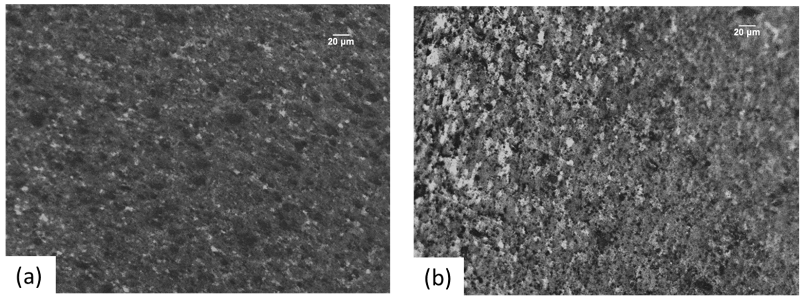
For validation, experiments on the FE100 friction extrusion machine by Bond Technologies, which can apply forces up to 1000 kN, generate torques of 3500 Nm and reach rotational speeds of 1000 rpm, were carried out. Gas-atomized 6061 aluminum powder with spherical particles under 106 μm was used as the feedstock, stored in a dry air environment. The microstructure of the extruded rods was analyzed by using an optical microscope.
Previous research indicated that thermal analysis or density proof alone was insufficient for ensuring the successful extrusion of massive pieces. The Piwnik and Plata criterion was utilized to assess the internal stress state of the workpiece. The parameter
w is defined by the time integral of the ratio of pressure (
p) to the effective stress (
) acting on the material when it exceeds the limit value
wlim determined by temperature, as indicated by this criterion:
For each simulation step, this was approximated by:
where
n is the total number of steps,
j is the
j-th step,
i is the
i-th node and Δ
tj is the time per step. In these simulations, the pressure
p was replaced by the mean stress
σmean due to the porous nature of the workpiece, preventing calculation of local pressures.
The simulation model had an automatic calculation of
w and
wlim for each node at each step thanks to the development and integration of a specific Fortran routine.
This routine also accounted for the relationship between these parameters, by calculating the ratio and coloring the element differently as a function of the reached bonding condition or not.
After the bonding conditions were evaluated, torque, energy from axial thrust and rotational movement energy were extracted and analyzed. The total energy demand was computed by summing the energy from axial thrust, automatically exported from the post-processor of the software, and rotational movement, calculated as follows:
where
Er is the energy for rotational movement,
ω is the rotational speed and
C is the torque.
In traditional hot extrusion, the energy demand includes two main components: the fusion/heating phase and the energy linked to the axial thrust of the tool, that for the hot extrusion was also automatically exported from the post-processor of the software.
During the fusion phase, scraps are re-melted to form a new billet, while the heating phase involves pre-heating the billet before extrusion (between 350 °C and 450 °C) to keep the alloy soft enough for extrusion but not too hot, to avoid defects. These thermal energy components were adjusted by an efficiency coefficient (η), which accounts for heat losses and equipment efficiency, typically around 28% [
26], and then multiplied by the extruded mass (m [g]).
Overall, the total energy demand for hot extrusion is calculated as:
with
: melting point minus room temperature [°C];
c: aluminum specific heat capacity [J/(°C∙g)];
c*: heat of fusion [];
: 40 °C (from the 660 °C of the melt to an overheat temperature of 700 °C);
: billet final temperature minus starting temperature (equal to 350 °C and 20 °C, respectively).
2.2. Dynamic Recrystallization and Microstructural Evolution
In this work, the grain size evolution was simulated following the model originally developed to define recrystallization during the extrusion process, adapted for the Friction Stir Extrusion process reported in [
27]. The initial grain size
d0 was approximated by describing a single diametrical value, calculated from the height and width dimensions of the grains in the sheet, with no previous rolling process involved. The following equations were used to compute the final grain diameter after recrystallization:
where
indicates the recrystallized grain diameter;
δ is the subgrain size [µm];
is the average strain;
are material calibration constants (4.75, 0.4, 85.192, 14.88 and 1.68 × 10
5, respectively) [
28];
Z is the Zener–Hollomon parameter;
C = 3.36 × 10
−9 m
−1, n = 5.577 and Q is the activation energy for AA6061 (196,000 J/mol·K) [
27];
R is the universal gas constant (8.341 J/mol·K);
indicates the maximum strain rate during the extrusion process.
By utilizing these equations and constants within a post-process Fortran routine, the model allowed for the accurate prediction of grain size evolution during the FSE process.
The most interesting aspect of the proposed model is that the developed routines are able to accurately predict the final grain size, regardless of the starting material grain dimensions. This is due to the independence of the calculated variables with respect to the density and, therefore, porosity of the starting material.
Indeed, the only variable necessary to predict the final grain size is the initial average dimensions of the starting grain. The only difference, therefore, between considering powder, scraps or bulk materials as the starting material is the need to insert as the starting grain size only the transversal dimension of the grain, being practically the same as the longitudinal one for the powder or for scraps (if sufficiently small), or both the transversal and longitudinal dimensions for bulk materials.
3. Results and Discussion
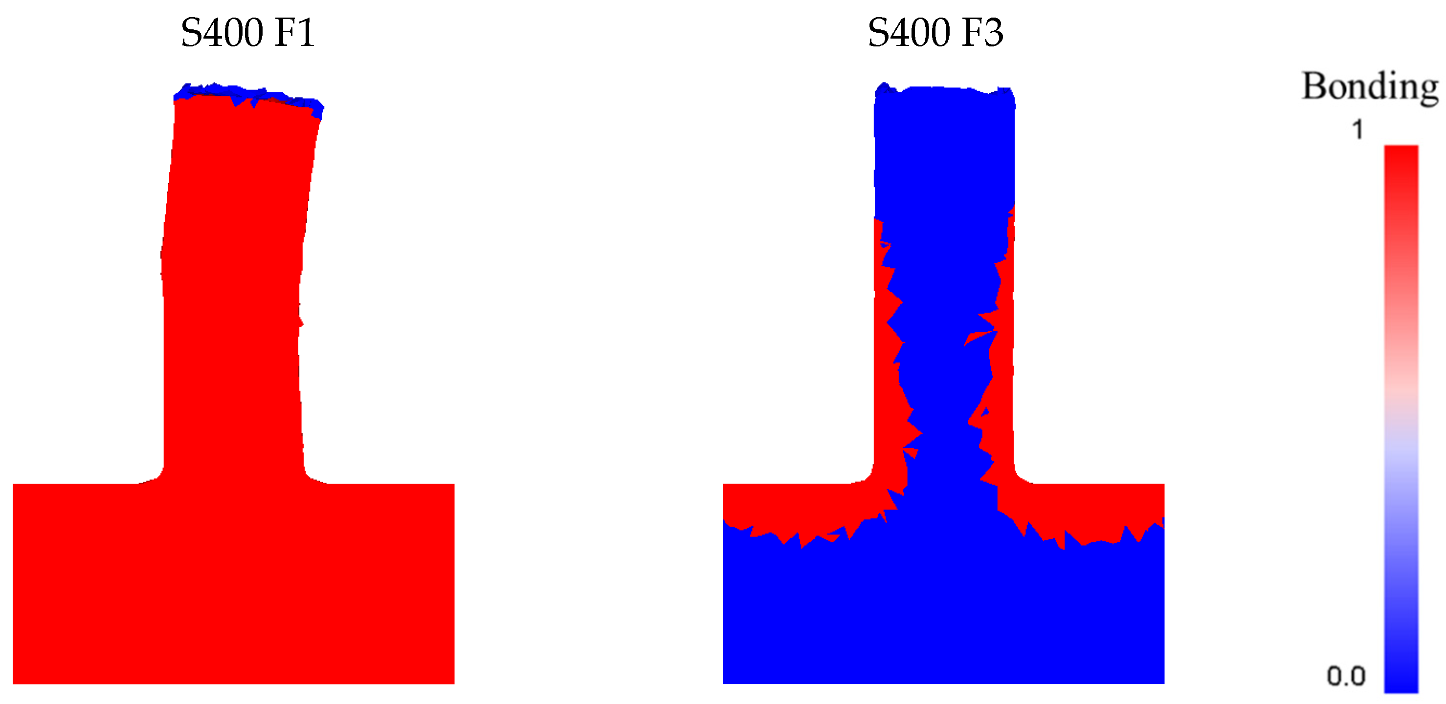
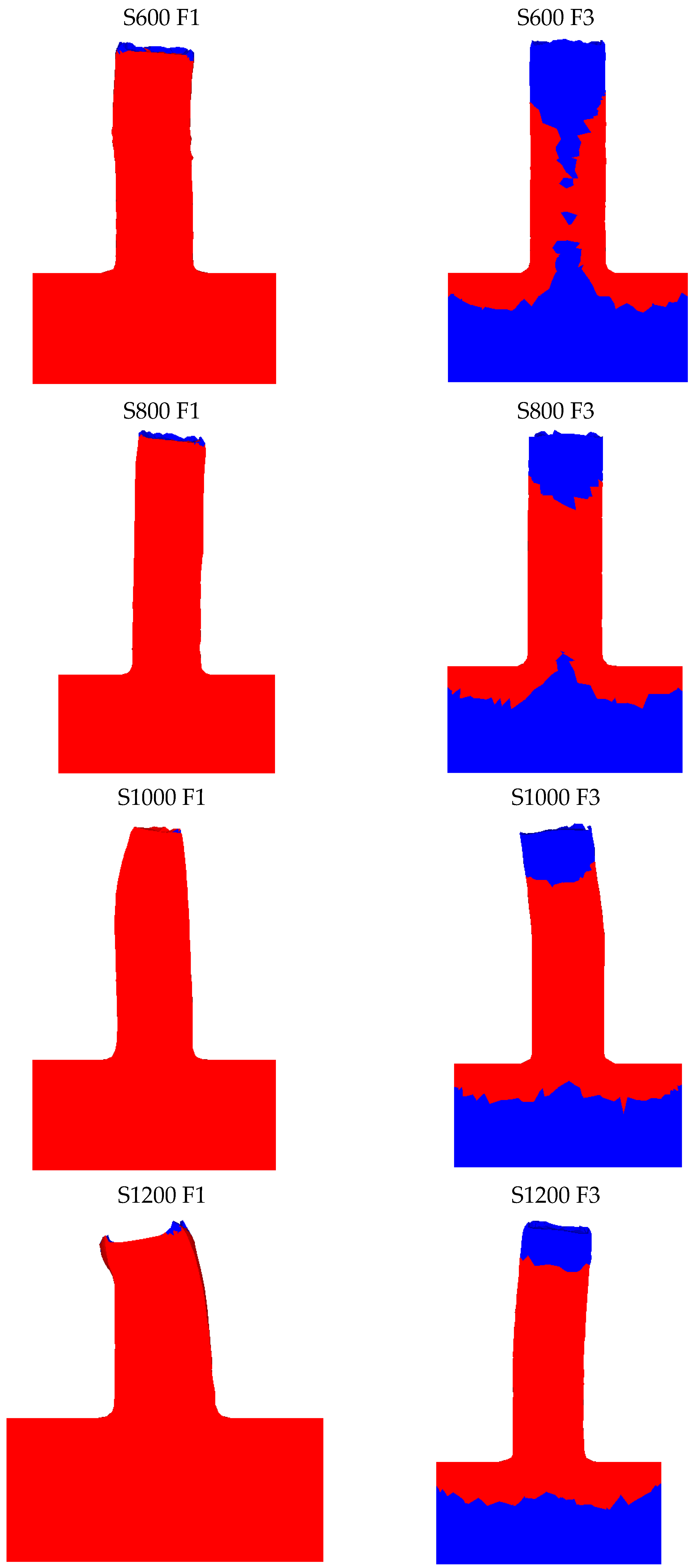
Incorporating a specialized Fortran routine into the simulation models enabled the automatic computation of the variables w and wlim for each node in the pre-processor phase. This integration facilitated the embedding of the relationship between these parameters directly into the model. To visually represent the Piwnik and Plata criterion, a new user-defined variable named “bonding” was introduced. This variable allowed the simulation to color-code elements where w > wlim in red and where w < wlim in blue, thus providing a clear graphical indication of whether the criterion was met.
This approach demonstrated the capability of inverse FSE methods to produce fully dense and solid rods. The possibility to conduct this type of prevision is fundamental, considering that previous studies have shown that thermal analysis of the FSE process, alone, does not guarantee the extrusion of solid, defect-free pieces [
29,
30].
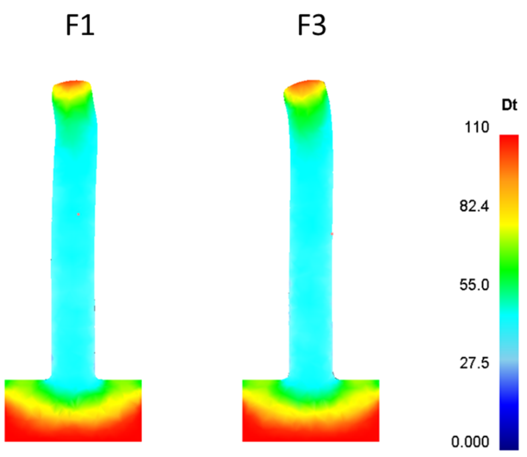
The obtained results are reported in
Figure 1. In this figure, only the first 5 mm of the extruded rods are shown. This choice was made based on the intention to study the effects of the process parameters on the starting bonding conditions of the Friction Stir Extruded rods.
As previously discussed, there has been a growing interest in the microstructure of aluminum alloy extruded profiles within the extrusion industry. To address this issue, an additional Fortran routine was incorporated into the post-processing stage of the DEFORM™ 3D software (13rd version 13). Originally crafted for use with the traditional extrusion process and compatible with Qform Extrusion software [
28], this routine was tailored to suit this new technology and software platform. The updated routine successfully enables the prediction of average grain size independent of the type of aluminum alloy being considered.
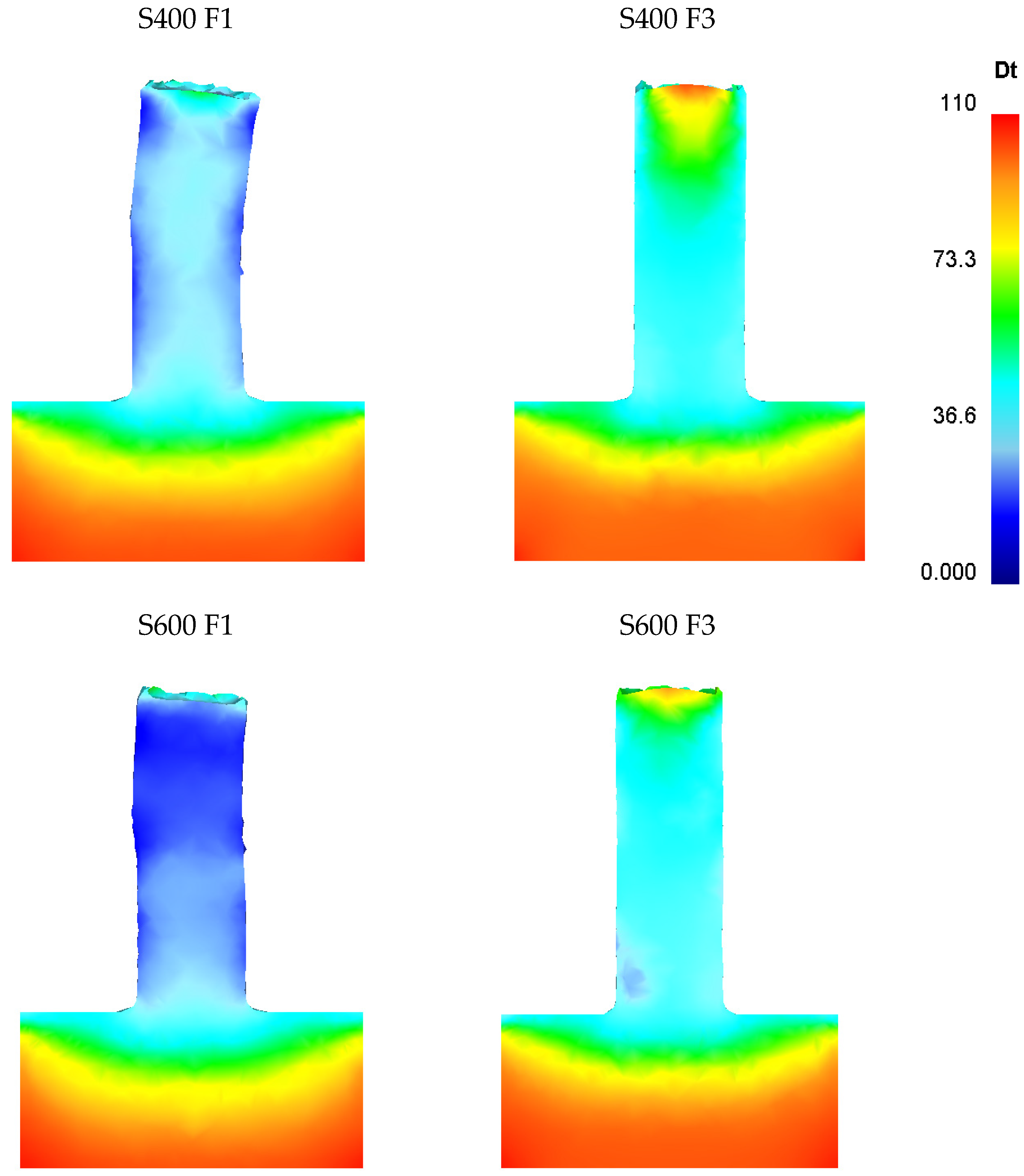
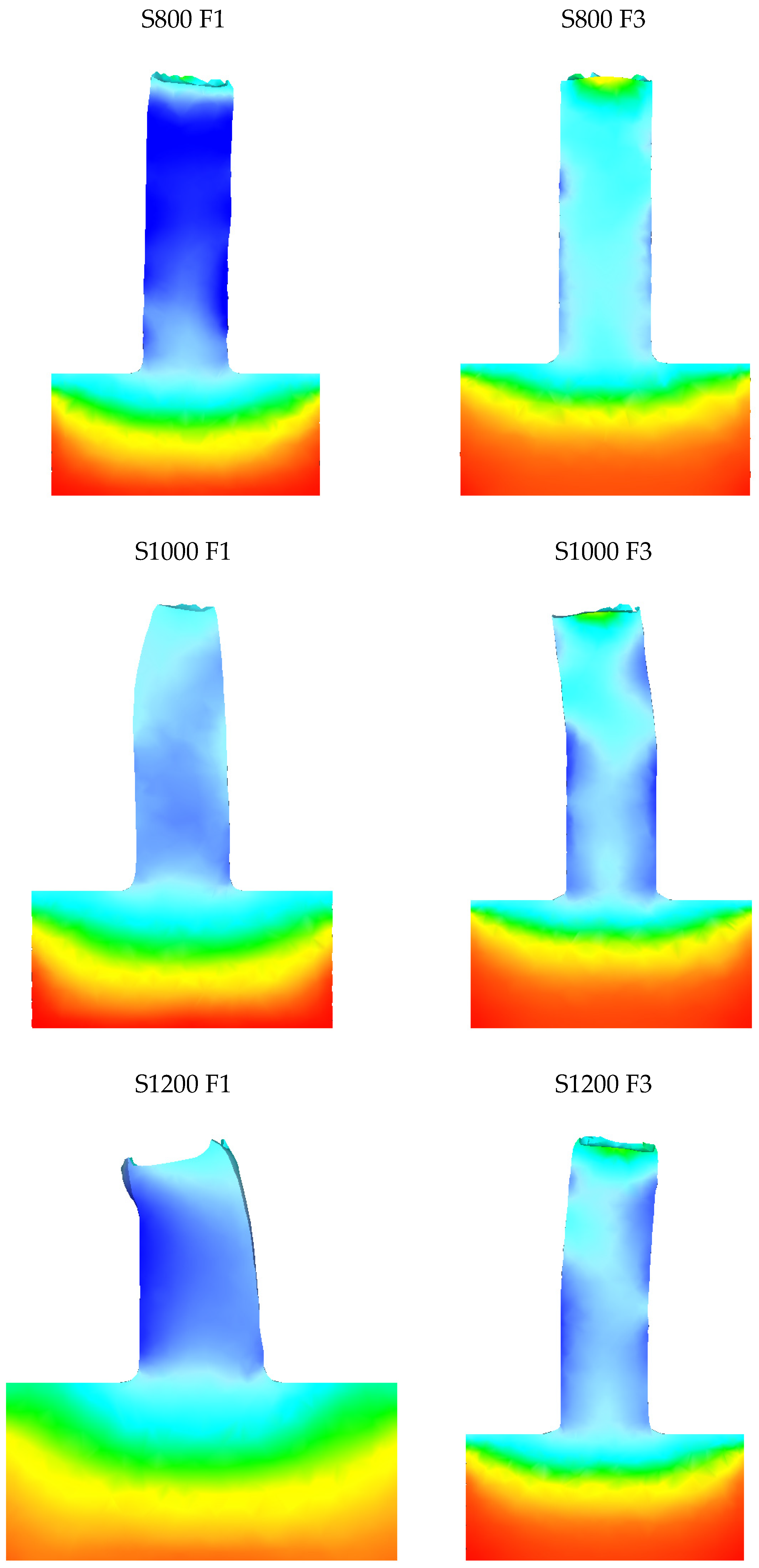
In the specific scenario analyzed, metal powder served as the starting material. Due to their small size and the machining processes that created them, these chips can be considered to have relatively uniform and equiaxed grains. Therefore, only the grain thickness is plotted. The microstructural evolution altered the original grains into an equiaxed and extremely fine-grained structure, with average grain sizes spanning from a few microns to 20–30 μm, as it is possible to observe in
Figure 2.
By analyzing this data within the routine, the microstructural changes in the extruded sample were assessed through an FEM model.
At the 5-mm mark from the primary die stroke, a noticeable grain refinement is observed, as depicted in
Figure 2.
A noticeable difference can be observed in the rods based on the descent velocity of the tool, while maintaining constant rotational speed. This difference is even more pronounced at medium to low rotational speeds, mainly up to 800 rpm. Considering the simulative results obtained, the optimal conditions seem to occur at intermediate rotational speeds (600–800 rpm) combined with a lower descent velocity (1 mm/s). Under these two conditions, the smallest sizes of statically recrystallized grains can be observed, with average dimensions around 10–20 µm. This behavior can be ascribed to the combined effect of thermal input and axial stress exerted on the material by the rotating tool. Indeed, these findings must be evaluated concerning the S/F ratio. In the context of Friction Stir Processing (FSP), which encompasses the Friction Stir Extrusion (FSE) process, the ratio between the tool’s rotational speed and its feed rate—here referred to as descent velocity—serves as a reliable indicator of the heat generated during the process. This S/F ratio is crucial as it directly affects the thermal dynamics during FSP operations. At higher rotational speeds and low descent velocities, the grains undergo more significant dimensional changes due primarily to the increased thermal input, leading to grain growth through static recrystallization.
Conversely, the worst conditions are found at low rotational speeds and high descent velocities. Under these parameter combinations, achieving complete bonding in the first 5 mm of tool descent was not possible, as shown in
Figure 1.
The recrystallization model partially captures this condition, revealing large grains throughout the extruded material, with average dimensions comparable to the original starting material. This indicates that the powder was only partially engaged in the active processing.
The observed trends in grain evolution in the results align well with the existing literature. Notably, Buffa et al. achieved similar outcomes using the same starting alloy in chip form and low rotational speeds (300 to 500 rpm). The grain sizes obtained in the fully extruded section, ranging from approximately 15 to 30 μm, are also consistent with values reported in the literature [
31].
Furthermore, the ability of the proposed predictive model to successfully forecast the trend in average grain size within the extruded materials is not to be underestimated. Indeed, the simulated results were confirmed considering both the existing literature and the experimentally obtained results. The good match between the simulated results and the literature referenced is illustrated in
Figure 3, where the detailed results produced by the newly developed routine applied to our simulation model are compared with those from the Friction Stir Consolidation (FSC) process. The FSC process closely resembles the Friction Stir Extrusion (FSE) process, with the primary difference being the presence of a hole in the primary die in the FSE process [
32].
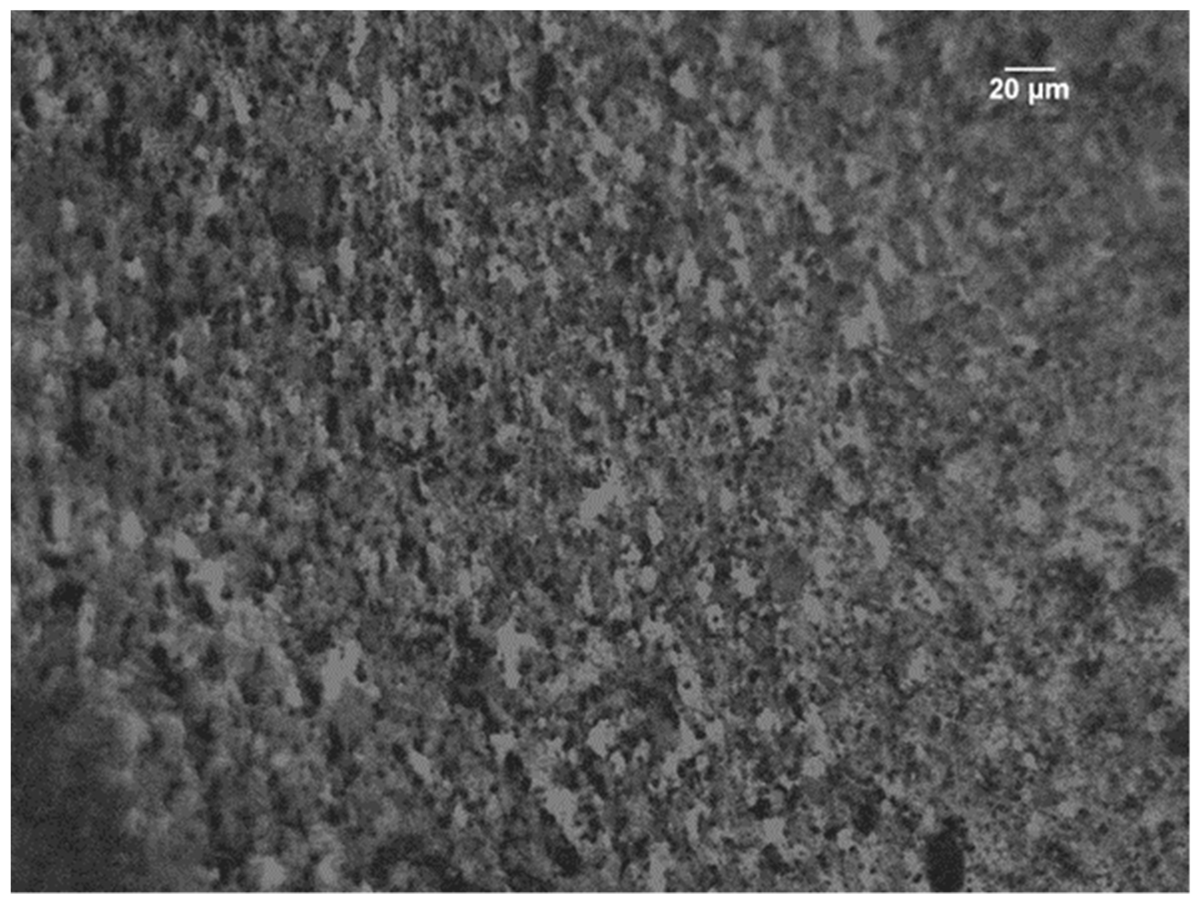
From the experimental point of view, both the average grain dimensions and the grain size trend within the transverse section of the extruded rods were confirmed.
As an example, analyzing the extremes of the technological window by considering the rotation speeds operable by the experimental instrumentation (maximum 1000 rpm) and the minimum and maximum descent velocities, in
Figure 4 both the microstructures of FSEed rods with S400 rpm and 3 mm/s and S = 1000 rpm and F = 1 mm/s are shown. As obtained through the simulative results and also in the experimental tests, the rods extruded with the lowest rotational speed and the highest descent velocity show larger grains with respect to the rods extruded with S1000 rpm and F equal to 1 mm/s.
In
Figure 5, it is clearly traceable; within the rod extruded with 1000 rpm and 1 mm/s, the variation of the bigger external grains and the smaller internal ones is demonstrated.
As previously mentioned, the same FEM model was also used to simulate hot extrusion, obviously eliminating the rotational movement of the tool. The results concerning the bonding condition are not reported as they are irrelevant. In fact, in the case of traditional hot extrusion, the starting material is a billet that is already fully dense, so it would not make sense to study whether bonding has occurred downstream of the extruder. On the contrary, it is interesting to note how the recrystallization model provides significant results even for traditional extrusion. The obtained results are shown in
Figure 6.
The results show an average grain size of 50 µm in the extruded part, regardless of the extrusion speed. The values are in accordance with those in the literature for a 6xxx series alloy with comparable process parameters [
28,
33,
34,
35].
Regarding the energy demand, the comparison was made by considering all components of energy demands that contribute to the total energy expenditure. Specifically, the energy due to the rotational component and the axial thrust component for Friction Stir Extrusion and the axial thrust component and thermal expenditure for traditional hot extrusion. For the latter, the mass of material extruded during the simulation was calculated to be 4.88 g, allowing the thermal expenditure to be added to the axial component, already weighted against the actual extruded product.
The graphs below show the comparisons between the various energy expenditures. In particular,
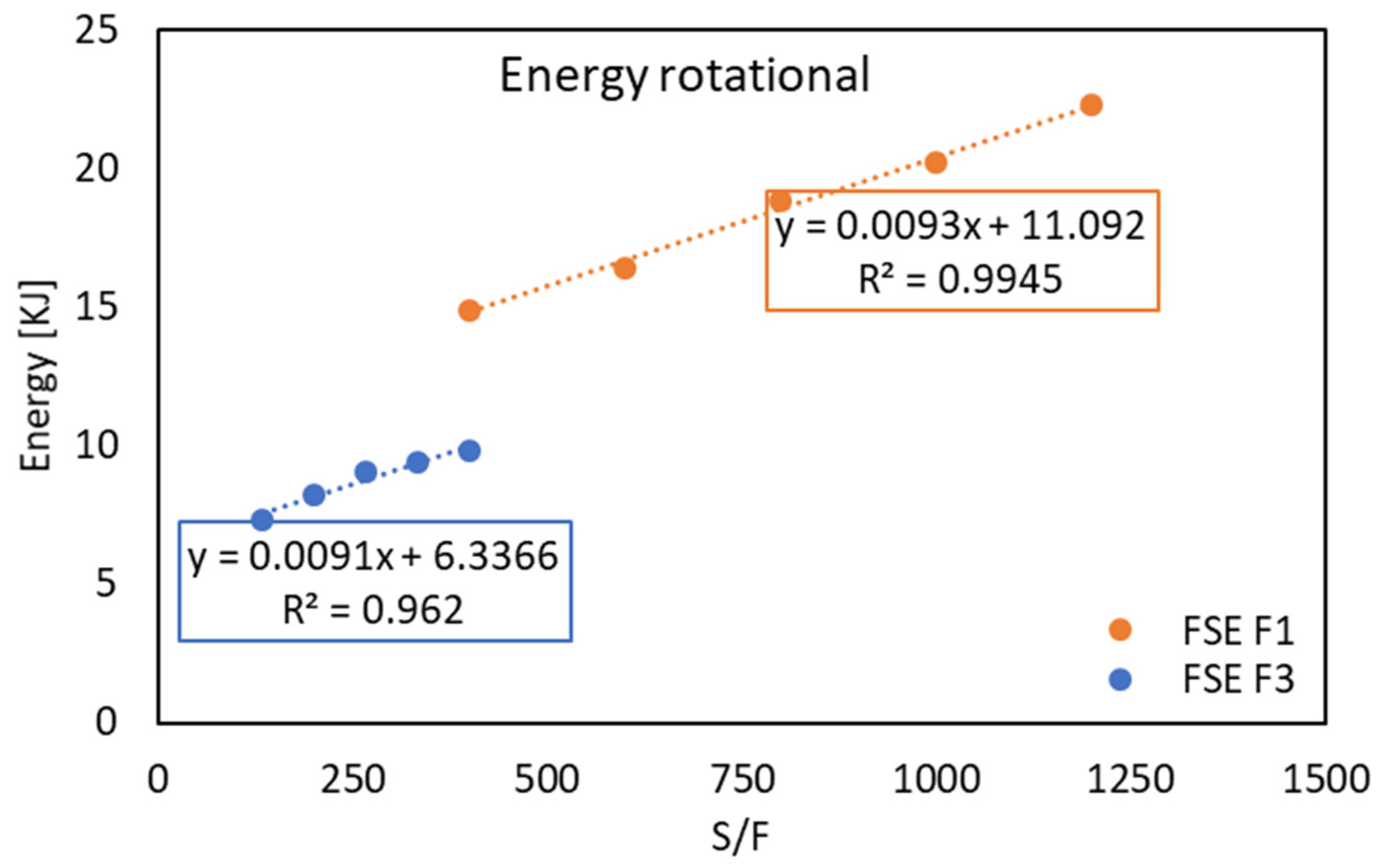
Figure 7 shows the energy values due to the rotational component of the FSE tool, and
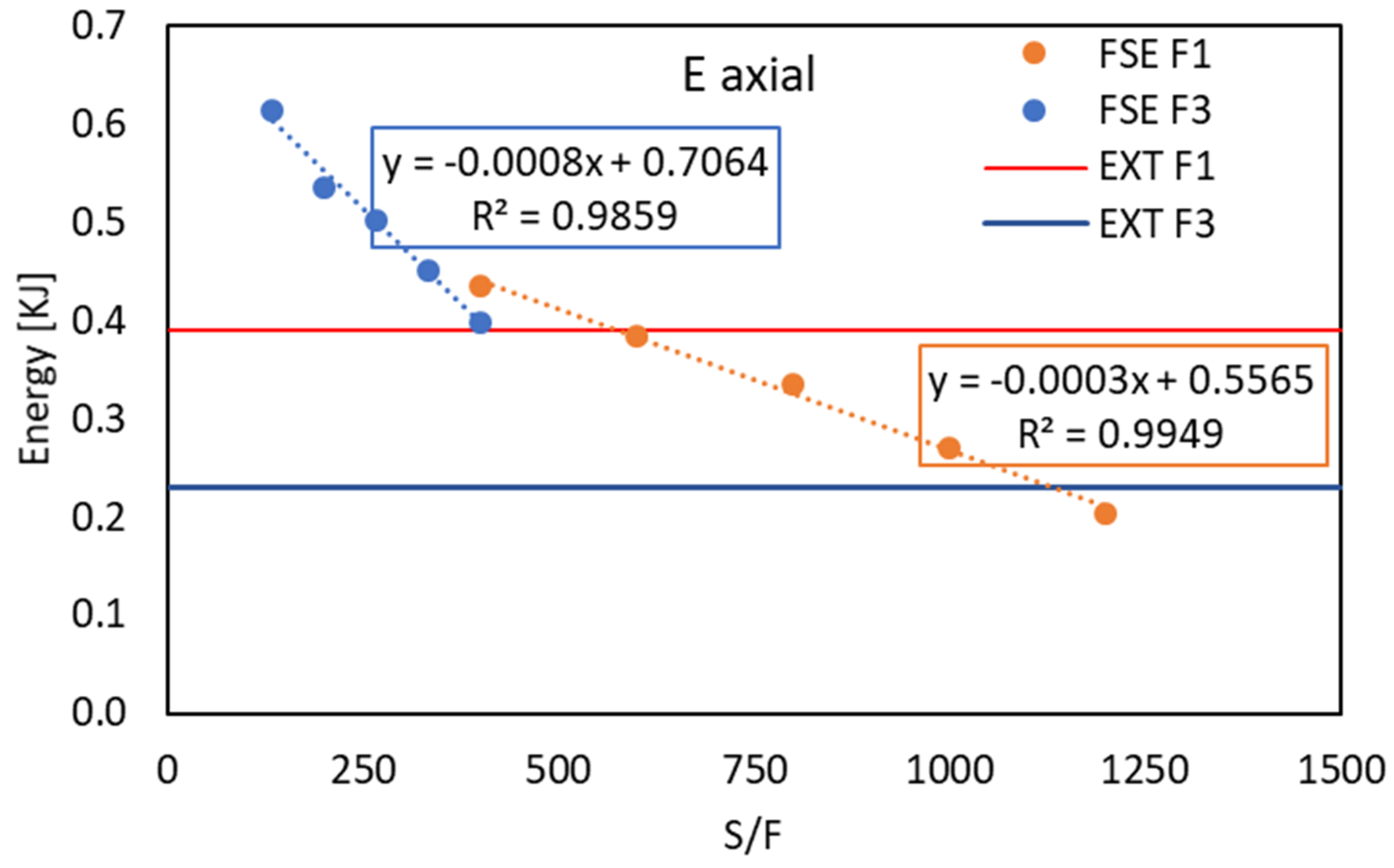
Figure 8 shows the energy due to axial thrust in FSE and traditional hot extrusion.
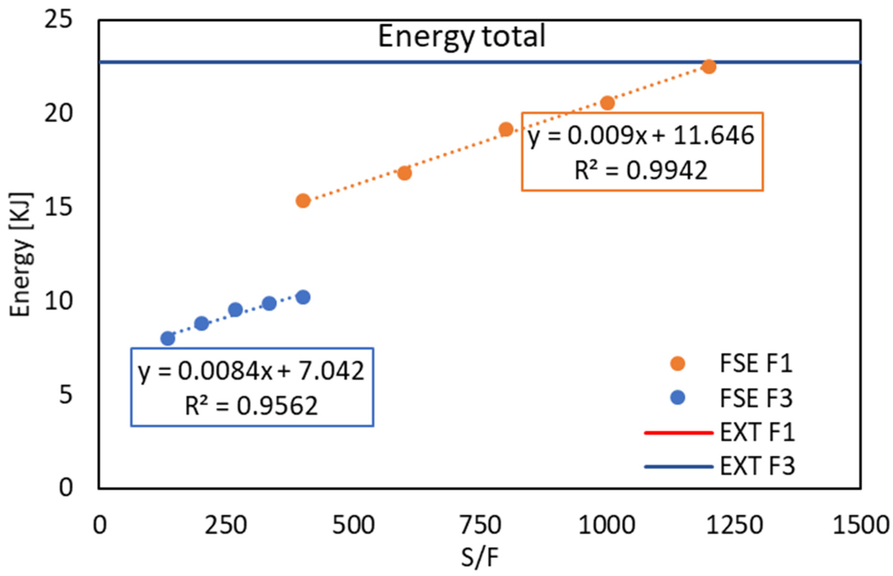
Figure 9 shows the total energy required to complete the various processes in the different combinations of process parameters for both FSE and traditional hot extrusion.
All the graphs report the ratio between the rotational speed and the descent velocity of the tool on the X-axis. This is due to the importance of this kind of parameter in the Friction Stir Processes, among which FSE stands out.
In
Figure 8 and
Figure 9, the energy demands related to traditional hot extrusion were plotted as a line, since the relating values are obviously independent from the S/F.
From the graph shown in
Figure 7, distinct behaviors characterizing the two different parameter combinations are evident. Indeed, it is clear that as the ratio between S and F increases, the energy demands due to the rotational movement of the tool increase, regardless of the tool’s descent velocity.
An excellent linear correlation was found between S/F and the rotational energy demand, with very high R2 values ranging from 0.962 to 0.9945. Furthermore, the rods extruded at a tool feed rate of 3 mm/s were proven to require about half the energy needed to extrude at a tool feed rate of 1 mm/s.
Regarding the energy due to axial thrust, a completely different behavior is observed compared to rotational energy. Specifically, in
Figure 8, it is noticeable that the energy trend is inversely proportional to the increase in the S/F ratio. Very high R
2 values, ranging from 0.9859 to 0.9949, are also calculated in this graph. Additionally, in this case, the axial energy required by the FSE process performed at a descent speed of 3 mm/s is higher than that required at a tool descent of 1 mm/s, regardless of the rotation speed.
For the hot extrusion process, the axial energy required for extrusion at 1 mm/s is higher compared to the same process at 3 mm/s. It is interesting to note that, in the case of a tool descent velocity of 3 mm/s, the axial energy is systematically much higher in the FSE process, regardless of the rotation speed. In the case of a tool descent velocity of 1 mm/s, the axial energy required by the hot extrusion process is closer to that required by the FSE, lower only in the case of the lowest S/F ratio.
The trend of the total energy is almost identical to that of the energy due to the rotational movement of the tool in the FSE process, as this component is by far the most dominant compared to the axial energy demand. In
Figure 9, very high R
2 values, ranging from 0.9859 to 0.9949, are found. The total energy demand of traditional hot extrusion for both extrusion speeds is almost overlapping, with higher values compared to the FSE process.
4. Conclusions
The integration of a specialized Fortran routine into simulation models improved the computation of critical variables and allowed for clear visual representation of bonding conditions in the FSE process. Results showed that inverse FSE methods produce fully dense and solid rods, with simulations accurately predicting grain size and bonding conditions.
The FSE microstructure showed much finer grains compared to traditionally hot extruded products.
In terms of energy demand, rotational energy demand in FSE was strongly influenced by the S/F ratio, and a 3 mm/s feed rate required about half the rotational energy compared to a 1 mm/s feed rate. Axial thrust energy displayed an inverse relationship with the S/F ratio, with higher demands at higher feed rates.
Overall, the total energy demand for FSE was lower than for traditional hot extrusion, making FSE more efficient. From both a microstructural and energy perspective, FSE was advantageous under the analyzed conditions, highlighting its effectiveness in producing high-quality extruded rods with optimized energy consumption.
The developed simulation model proved valuable for predicting process outcomes and guiding parameter optimization in Friction Stir Extrusion.
The most important perspective of the proposed model is that the developed routines enabled precise predictions of final grain dimensions irrespective of the initial grain size. The model can be easily adjusted for various starting materials, such as chips, powder or flat material, by altering parameters related to initial grain size (including longitudinal and transverse dimensions if the starting material does not have equiaxed grains). Modifications to the initial density and aluminum alloy parameters in the simulation, along with the relevant variables in the post-processing prediction model, ensure adaptability to different material forms.
