Abstract
The mechanical properties of woven jute fiber-reinforced PLA polymer laminates additively manufactured through Laminated Object Manufacturing (LOM) technology are simulated using the finite element method in this work. Woven jute fiber reinforcements are used to strengthen bio-thermoplastic PLA polymers in creating highly biodegradable composite structures that can serve as one of the environmentally friendly alternatives for synthetic composites. A LOM 3D printer prototype was designed and built by the authors. All woven jute/PLA biocomposite laminated specimens made using the built prototype in this study had their tensile and flexural properties measured using ASTM test standards. These laminated structures were modeled using the ANSYS Mechanical Composite PrepPost (ACP) module, and then both testing processes were simulated using the experimentally measured input values. The FEA simulation results indicated a close match with experimental results, with a maximum difference of 9.18%. This study served as an exemplary case study using the FEA method to predict the mechanical behaviors of biocomposite laminate materials made through a novel manufacturing process.
1. Introduction
Fiber-reinforced polymer composites (FRPCs) are multi-phase materials with superior engineering properties, such as high strength and light weight, compared to typical single-phase engineering materials. They are nowadays widely used as structural components of products in industries such as aerospace, automotive, wind turbine, medical, and sports [1]. However, the difficulties in the scrap disposal of retired traditional FRPCs are becoming an increasingly significant problem due to the low biodegradability and recyclability of such material [2]. Natural fiber-reinforced biopolymer composites, due to their environmental and economic advantages, are promising alternatives to their conventional synthetic fiber-reinforced counterparts. Natural fibers are high in specific strength and modulus, biodegradable, affordable, renewable, and of low carbon footprint, which makes them already widely adopted by the automobile industry [3,4], construction industry [5,6,7], and sports industry [8,9,10]. Biopolymers are produced by or derived from living organisms, such as plants and microbes, rather than from petroleum, making them renewable and mostly biodegradable. While biopolymers make up only a small percentage of today’s polymer market, it has been predicted that they can replace 30–90% of petroleum-based polymers [11]. Over the most recent two decades, investigations have increasingly focused on natural fiber-reinforced biopolymer composites. Plackett et al. [12] employed a film-stacking process to create composites by converting a commercial L-polylactide to film and combining it with jute fiber matting. They found the tensile properties of composites produced between 180 °C and 220 °C were significantly higher than those of polylactide alone. Liu et al. [13] tested the biodegradability of jute/PBS biocomposites in compost soil and reported that factors such as the fiber–biopolymer ratio, fiber diameter, and fiber surface treatment would affect the biodegradability of the biocomposites. By using compression molding, Islam et al. [14] created industrial hemp fiber-reinforced Polylactic Acid (PLA) biocomposites that were both long (aligned) and short (random and aligned). Alkali was applied to the fibers to enhance PLA bonding. They discovered that interfacial bonding was enhanced by alkali treatment, which also resulted in improved mechanical characteristics for the biocomposite. Interfacial shear strength (IFSS) studies supported this finding.
The major limitation of the engineering application of natural fibers is their relatively lower mechanical properties. Woven fabric composites offer some attractive properties compared to their non-woven counterparts. In particular, they offer adequate mechanical properties [15] and near-net-shape preforms or fabrics with high flexibility and stability with associated economies [16]. Song et al. [17] examined the physical behavior of hemp/PLA biocomposites. Hemp textiles with twill and plain weave were utilized as reinforcements, and a film stacking technique was employed to create hemp fabrics-reinforced PLA composites. They discovered that the PLA polymer could be reinforced more effectively with the twill structure than with plain weaving, thanks to its superior mechanical qualities and increased impact strength. Baghaei et al. [18] investigated the effect of the weave structure on the mechanical behavior and moisture absorption of the hemp/PLA woven fabric composites made by compression molding. In comparison to the composite created from winded hybrid yarn and basket fabric, the composite made from satin fabric exhibited the lowest porosities and the best mechanical qualities. Another important factor affecting water absorption is the weave pattern; while the composite made of hybrid yarn laminate absorbs more water than pure PLA, it absorbs less moisture than the other two weaves. Kandola et al. [19] studied and compared the physical, mechanical, and flammability properties of jute, sisal, and glass-reinforced PP and PLA polymers to enable their use in automotive applications. Mechanical test results showed that the tensile and flexural moduli of the PLA composites were higher than respective PP composites. In comparison, sisal composites have higher tensile and flexural moduli than jute composites. Jiang et al. [20,21] developed a new seven-step manufacturing process for making woven natural fiber-reinforced lightweight cores made using agricultural waste bounded by mycelium and soy-based bioresin as a matrix. The woven natural fiber skin material is the one that carries most of the loads, while the cured resin increased the sandwich structure’s shear ultimate stress, core shear yield stress, skin ultimate stress, and flexural strengths of the sandwich beams by factors of 1.5 to 6.5. Prior studies indicate that woven natural fiber-reinforced polymer composite can be beneficial in a variety of applications. Although previously analyzed by many researchers, most of their work focused only on mechanical property characterization. Modeling and simulations of such materials have been elusive. A combination of experimental and numerical investigations is greatly needed.
In this work, the authors investigate the mechanical characteristics of the 3D-printed woven jute fiber-reinforced PLA biopolymer composite using experimental as well as numerical approaches. PLA is one of the most common biopolymers in terms of production and use [22]. PLA has become a popular material due to it being economically produced from renewable resources. First of all, jute/PLA biocomposite prepregs are prepared through hand-layup using PLA powders and dry woven jute fabrics. Then, these prepregs are used to 3D print mechanical test specimens using a Laminated Object Manufacturing (LOM) 3D printer that has been designed and built by the authors. Both tensile and three-point bending tests are performed to obtain the jute/PLA biocomposite laminates’ mechanical characteristics. Further, a 3D numerical model is developed in ANSYS, and the tensile and flexural properties are simulated for the biocomposites. Finally, data analysis is performed, and conclusions are discussed based on both the experimental and numerical results.
2. Methods
This section introduces the LOM 3D printer prototype used for the study, details of the biocomposite material, methods of experimental mechanical tests, and finite element analyses using the ANSYS 2024 R1 software package.
2.1. The LOM 3D Printer Prototype
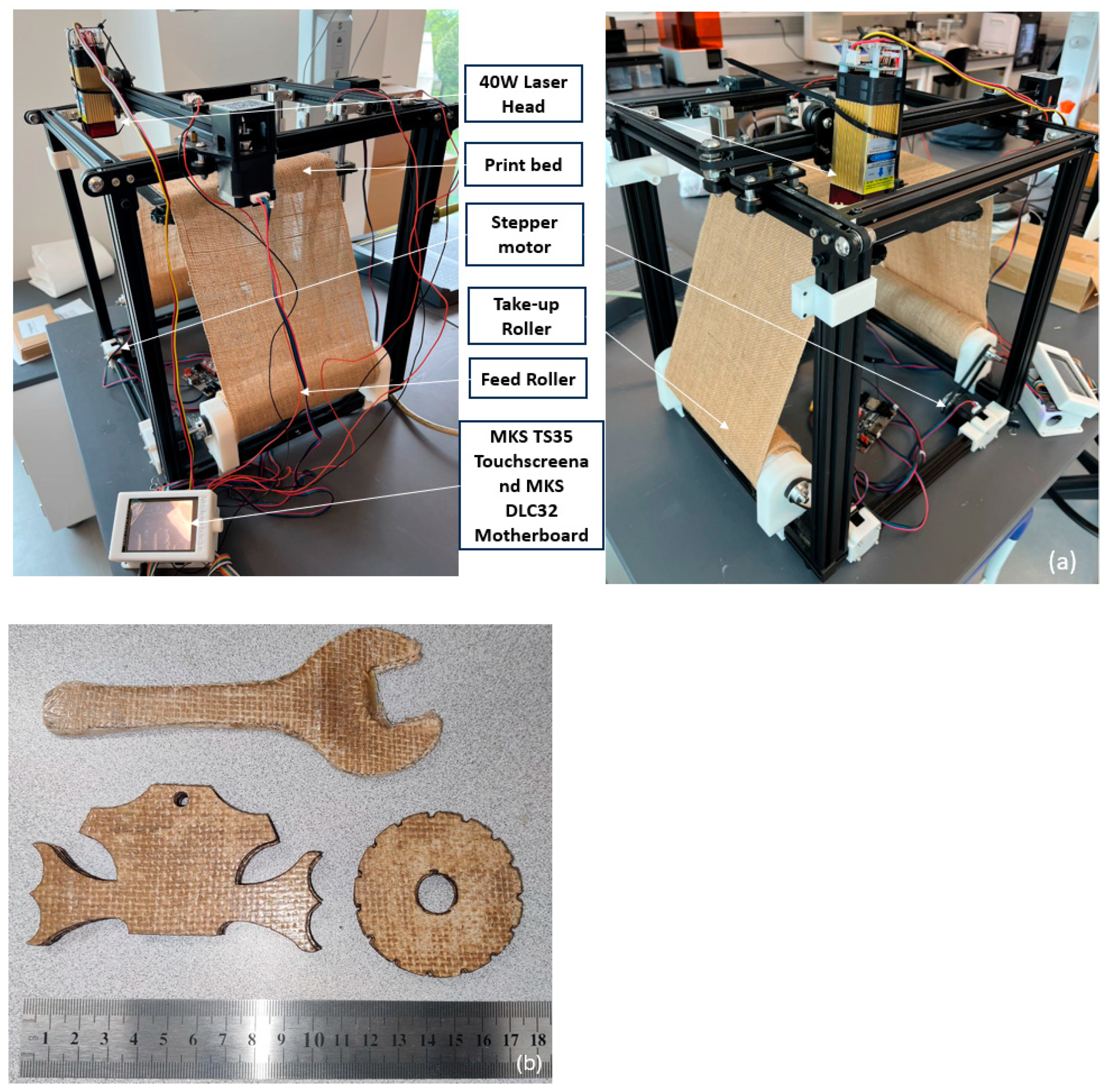
An in-house LOM 3D printer prototype was built to demonstrate the new additive manufacturing process that uses woven natural fiber-reinforced biopolymers (shown in Figure 1a). This prototype cuts pre-made prepregs made from thermoplastic polymer-infused woven fibers with a 40 W laser head. This prototype is equipped with an MKS DLC 32 motherboard and operated through an MKS TS35-R V2.0 touchscreen. The LOM system is programmed using G code. The purchased 40 W laser module falls under Class 4 safety standards, posing a significant risk to the eyes and skin. This laser came with protective splash guards around the head. When using the laser, the authors wore protective glasses to shield their eyes from the laser beam. Since the laser was controlled via G codes by a motherboard, the authors avoided proximity to prevent harm to their skin. Five Tronxy SL42S TH40 stepper motors are used to control the X, Y, and Z axes of the printing platform, both the material feeding and the take-up rollers, respectively. The size of the printing platform is 220 × 220 × 300 mm. The material feed-up roller feeds the prepregs continuously. After the laser cuts the prepreg, a heated hand-held metal roller is used to manually press the cut portion of the current layer onto the layer beneath, and then the material take-up roller takes the unused materials away, leaving the laser-cut part in the building platform. This process allows the next layer of printing material to be placed just above the previous one, and the same process keeps repeating until all the layers of the model to be built are finished. The entire model is then thermally pressed so the thermoplastic polymers can be remelted to have all layers bonded together. Finally, parts are manually trimmed to remove excessive polymers and fibers on the edge (shown in Figure 1b).
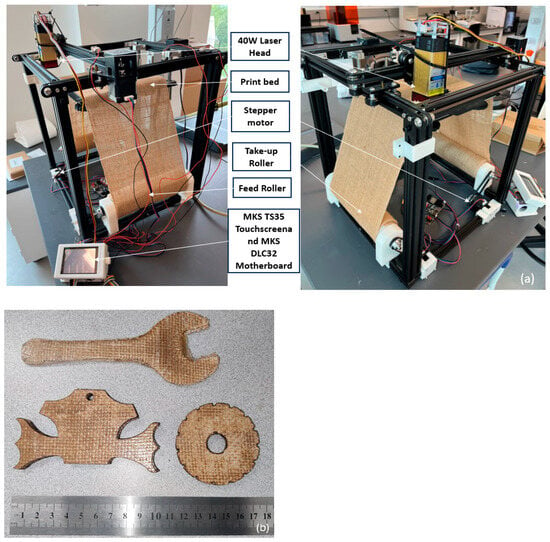
Figure 1.
(a) The LOM 3D printer prototype designed and built by the authors and (b) demo parts printed by the LOM 3D printer with a ruler in cm.
2.2. Materials
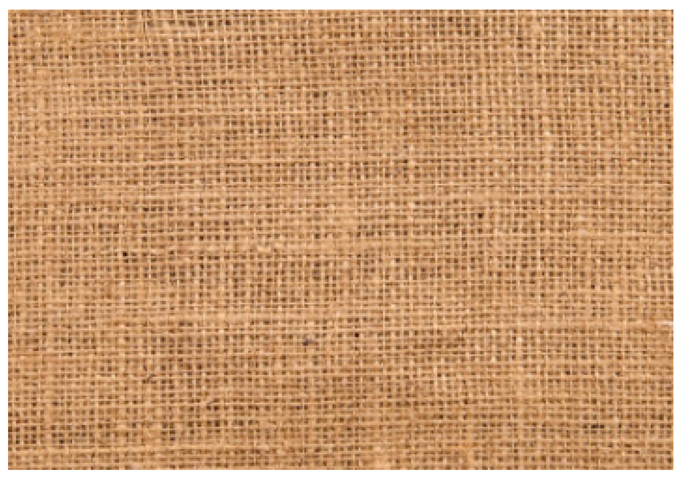
The natural fiber reinforcements used in this research are the most common commercially available plain weave woven jute fabrics (shown in Figure 2) provided by EnviroTextiles, LLC (Glenwood Springs, CO, USA), with a fiber thread density of 5 threads/cm and an average areal density of 338 g/m2. The average thickness was 0.071 mm for a single ply of this fabric. The jute fiber had been pre-treated to remove any gums and dirt by the manufacturer so no pretreatment was applied in this study.
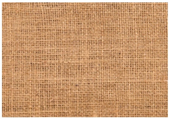
Figure 2.
Plain weave woven jute textiles used as reinforcements in this study.
Polylactic acid (PLA) biopolymer in the form of a white powder was provided by Nanochemazone. PLA (C3H4O2)n [23] is a biopolymer that can be made at a reasonable cost nowadays using renewable resources. Because of the ester linkages that connect the monomer units, it is classed as an aliphatic polyester, which can degrade naturally in situ via a hydrolysis mechanism; water molecules dissolve the ester bonds that make up the polymer backbone, resulting in a green matrix polymer substance [24]. When it comes to plastic filament for 3D printing, PLA is the most popular choice [25]. Its low melting point, strong strength, little thermal expansion, good layer adhesion, and high heat resistance when annealed make it the perfect material for 3D printing applications such as biodegradable and biocompatible composite structures [26]. Without annealing, PLA is the least heat-resistant of the major 3D printing polymers [26]. The melting temperature of PLA is between 170 °C and 180 °C [27].
2.3. Experimental Tests
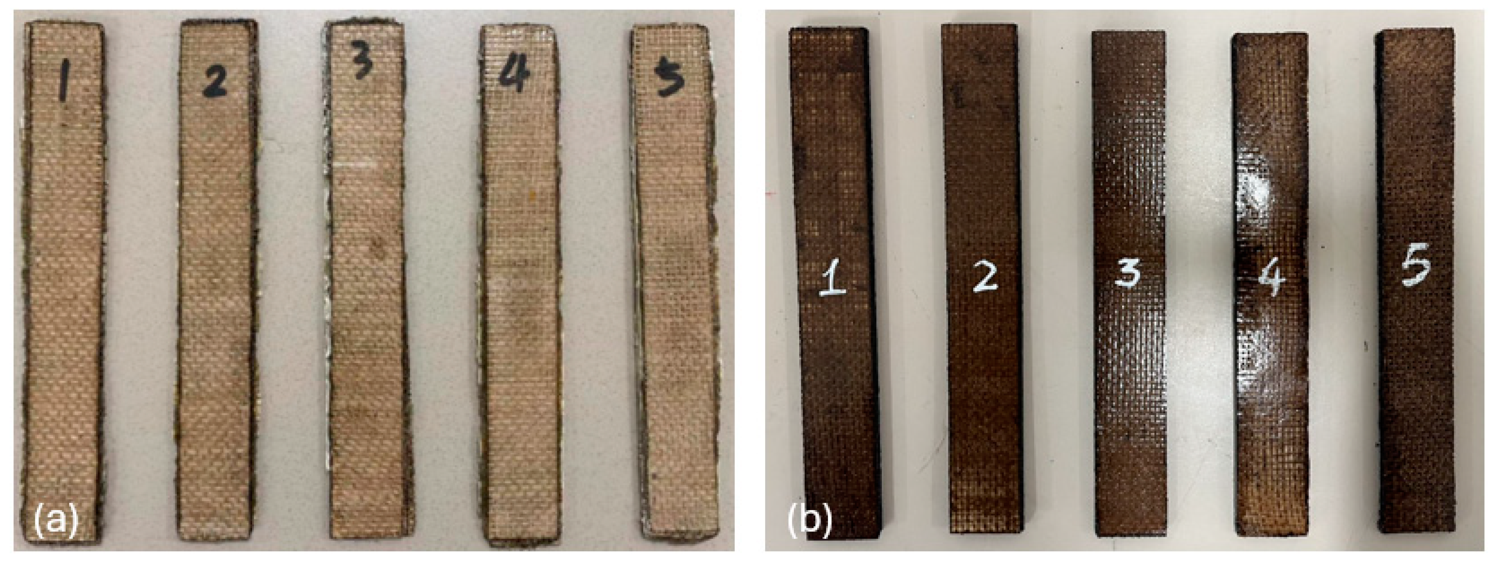
ASTM D3039/D3039M test standard was used for all tensile tests, with the target dimension of woven jute/PLA tensile test specimens being 175 × 25 × 2.5 mm. The .stl file for the woven jute/PLA biocomposite laminates tensile test was generated by SolidWorks 2024. Fusion 360 slicing software was then used to convert these data into cutting outlines for every layer, which were then uploaded to the prototype. Plies of the test specimens were laser-cut using the LOM prototype and stacked up to achieve the desired thicknesses. A total of five 6-ply (175 × 25 × 2.5 mm) and five 8-ply (175 × 25 × 3.5 mm) woven jute/PLA tensile specimens were fabricated using the LOM prototype. All specimens made underwent post-processing via thermal pressing; they were sandwiched by two Dupont Kapton HN Films and thermally pressed for 10 min in a Carver 4120 thermal press at 180 °C under 0.5 MPa. Test specimens made using the LOM approach are shown in Figure 3.
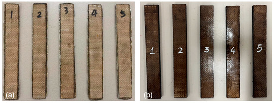
Figure 3.
The five LOM-printed woven jute/PLA biocomposite laminates: (a) 6-ply, (b) 8-ply [28].
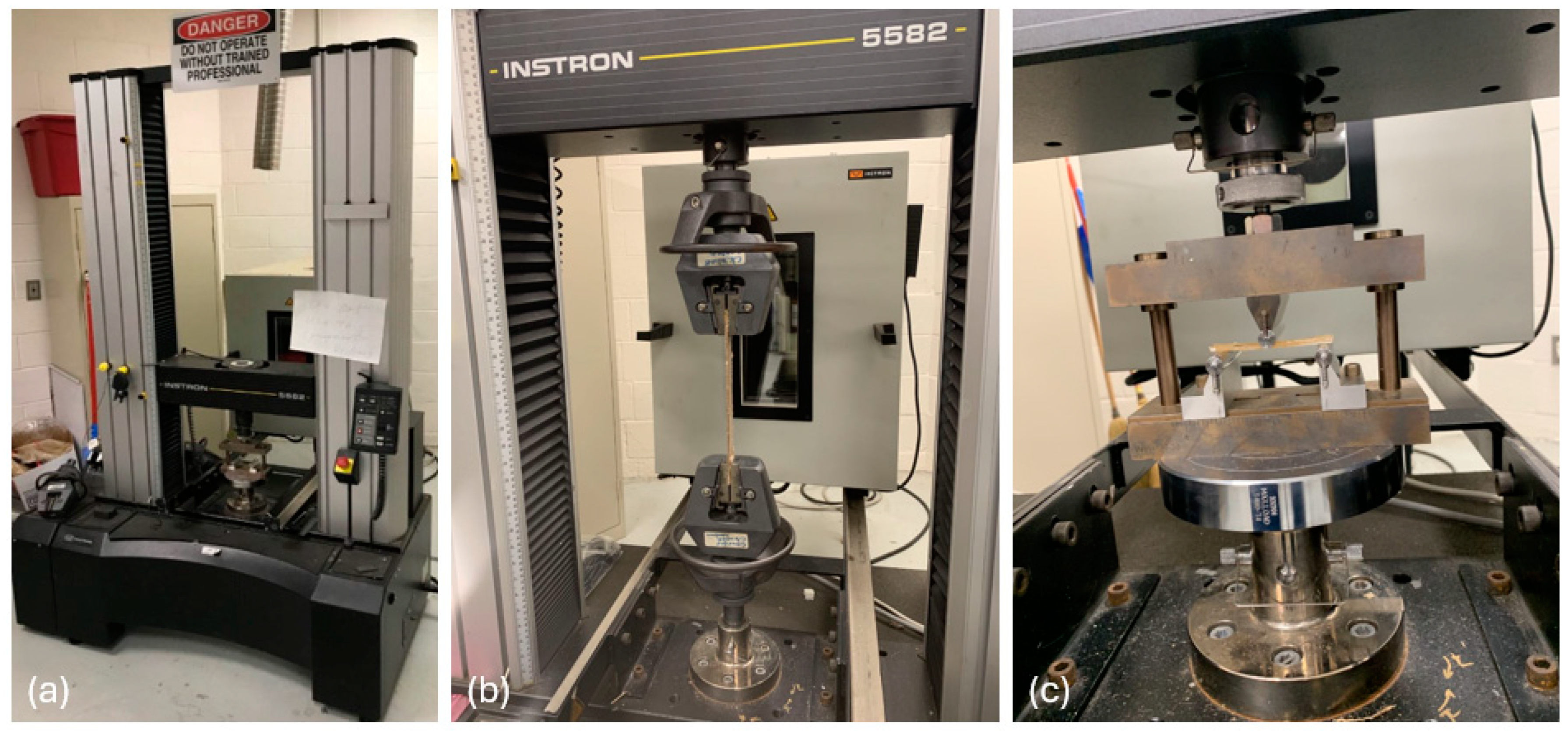
The tensile properties of LOM printing specimens were measured using an INSTRON 5582 Universal Testing Machine (UTM), as depicted in Figure 4a. The experimental setup for all tensile tests is shown in Figure 4b. The testing speeds were set at 2.0 mm/min according to ASTM D3039 to account for the distinctive characteristics of different materials. The UTM system automatically collected the tensile force–displacement data via the fixture head. The authors used these data and the dimensions of the test specimens to calculate the corresponding tensile stress–strain data and then the stress–strain curves. The ultimate tensile strengths and elastic moduli were evaluated during the tensile testing. The elastic moduli were computed by averaging the slopes of the tensile stress–strain curves in the linear area of five tested samples. The ultimate tensile strengths were ascertained from the maximum tensile stresses attained during testing.
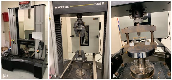
Figure 4.
(a) The INSTRON 5582 UTM used for mechanical tests, (b) tensile test setup, and (c) flexural test setup.
Three-point bending tests were carried out to determine both the flexural strengths and moduli of the woven jute/PLA biocomposite laminates following ASTM D7264/D7264M standard. The objective dimensions of the specimen were 76.2 × 13 × 4 mm. With the LOM prototype, a set of five 12-ply (76.2 × 13 × 4 mm) and five 16-ply (76.2 × 13 × 7 mm) flexural test specimens were made so the desired thickness could be achieved. These specimens also underwent post-processing via thermal pressing; they were sandwiched by two Dupont Kapton HN Films and thermally pressed for 20 min in a Carver 4120 thermal press at 180 °C under 0.5 MPa. Figure 5 shows the flexural test specimens.

Figure 5.
The five LOM-printed flexural test specimens: (a) 12-ply, (b) 16-ply [28].
The three-point bending test setup is shown in Figure 4c, and these tests were performed at a constant speed of 1.0 mm/min based on the test standard. Using the same UTM system, the corresponding flexural stress–strain data were automatically collected. The highest flexural stresses attained throughout the tests were used to record the ultimate flexural strengths, and average slopes of flexural stress–strain curves that resulted from the examination of the five tested samples were used to calculate the flexural moduli.
2.4. Finite Element Analysis
Using computer software to model and simulate the mechanical behavior of the biocomposite material under load can offer important insights into the biocomposite laminates’ strength, modulus, and other pertinent characteristics. Tensile test simulations can be used to forecast how the material would react to tensile stresses. The measured characteristics, geometric features, and boundary conditions of the woven jute/PLA biocomposite laminates were entered by the authors using the ANSYS 2024 R1 Advanced Composite Preprocessor (ACP). ANSYS ACP is a module for modeling, analyzing, and optimizing composite materials and structures. This simulation is capable of simulating the behavior of biocomposites in strain.
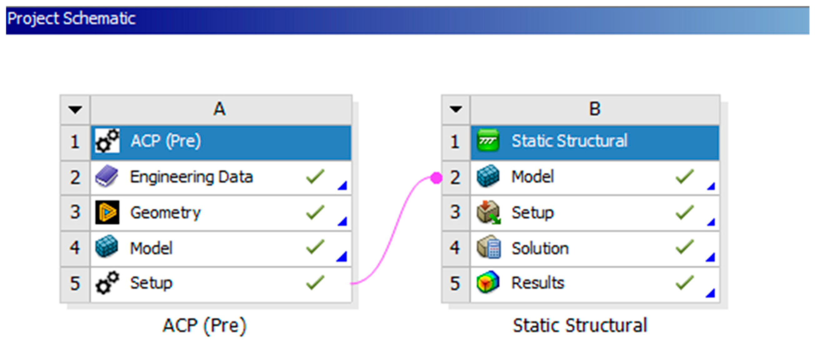
An exemplary overview of the project design that describes the FEA simulation techniques related to the tensile specimen is shown in Figure 6. The authors started the ACP module in Section A. Experimentally measured critical engineering data related to the woven jute/PLA biocomposites, as listed in Table 1, were input into this section. Six stack-up layers of woven jute/PLA biocomposites were designed using the geometry, with each layer considered isotropic as the material properties within the 2D plane are uniform. In the model, quadratic meshing was generated as it deforms realistically and can obtain geometric curvature with fewer elements. The corresponding material properties in Table 1 were applied to the stacked-up woven jute/PLA biocomposite laminates. After that, the setup was moved to the static structural (Section B). Here, comparable tensile stress and strain were simulated, and the simulation was solved to determine the outcomes. Detailed procedures of each distinctive task within each section are described below.
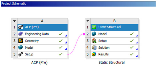
Figure 6.
Project schematic of the FEA simulation of LOM-printed woven jute/PLA biocomposite laminates tensile specimen.

Table 1.
Input Woven Jute/PLA Biocomposite Laminates’ Properties for Tensile Simulation.
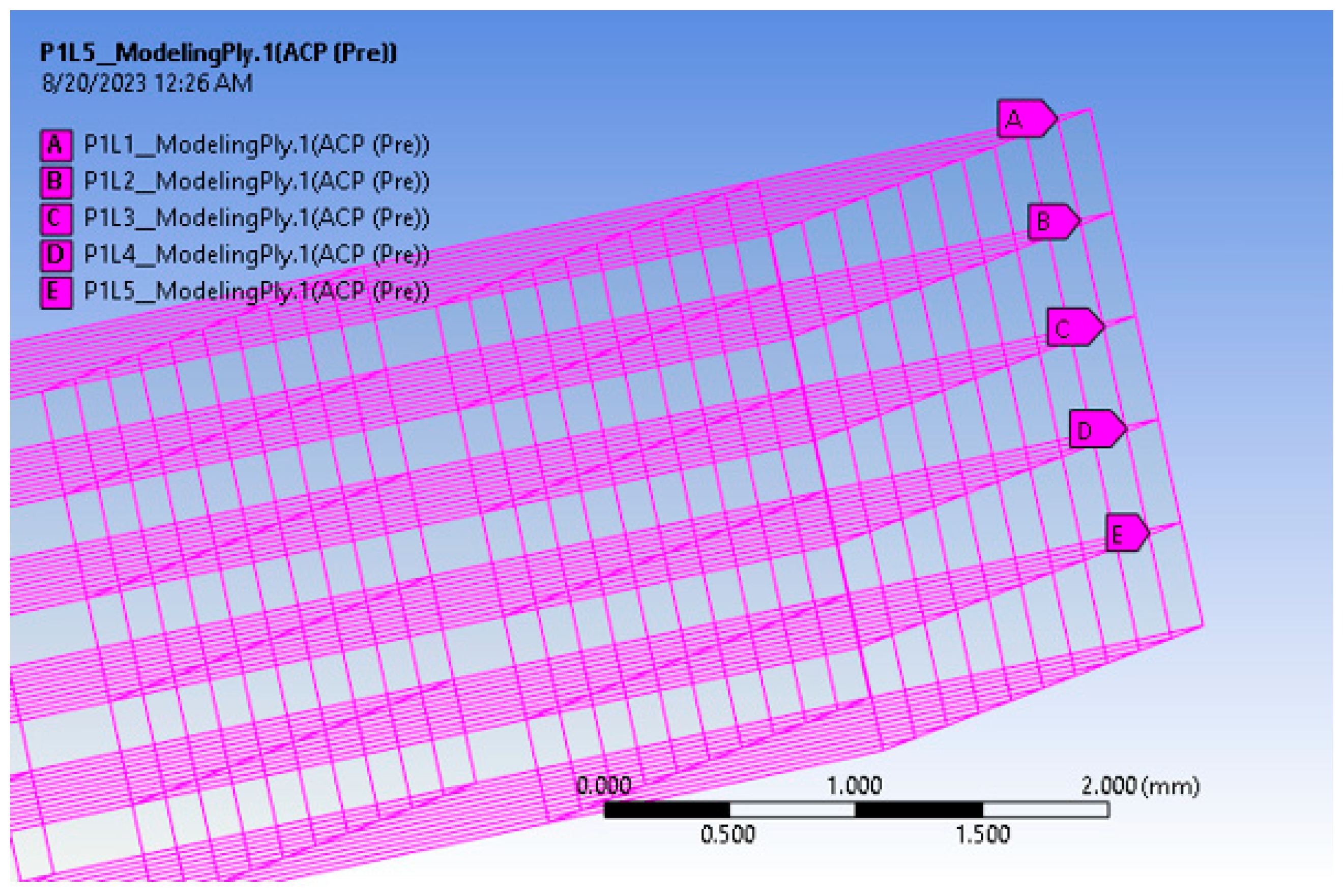
SpaceClaim 2024 R2 was used to build the geometry of the woven jute/PLA tensile test specimen once the material characteristics were supplied. The tensile specimens tested were 175 × 25 × 2.5 mm; therefore, it was made of 6 layers of 0.42 mm thick woven jute/PLA laminates. In order to construct a 6-layer woven jute/PLA biocomposite tensile specimen, the first layer was created in the geometry, and the subsequent five layers were created using the ANSYS ACP stack-up option. Figure 7 shows the 6-layer stacked model, and the 8-ply model was created in the same way.
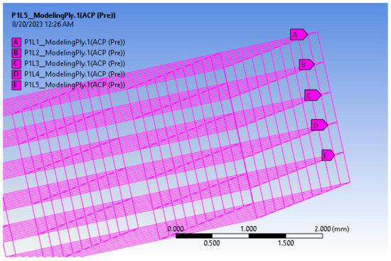
Figure 7.
Six-ply woven jute/PLA biocomposite laminates model.
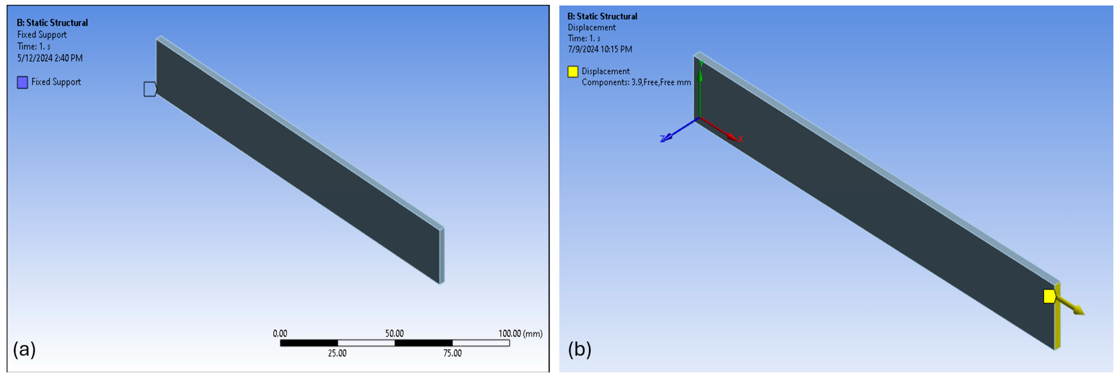
The edge-sizing operations started the mesh-generating process after the layer stack-up. Simulations were performed from large meshing sizes (32 mm) to smaller sizes (4 mm) until convergence of the results can be found. The ANSYS ACP model and configuration were moved to ANSYS Static Structural after meshing. Predicting how the woven jute/PLA biocomposite laminates will react to applied tensile stresses, restrictions, and displacements is the primary goal of ANSYS Static Structural. One end of the biocomposite specimen was used as a permanent support for the boundary conditions (shown in Figure 8a), and the actual maximum displacements measured during the tensile tests were applied to the other end of the model (shown in Figure 8b).
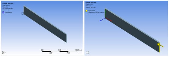
Figure 8.
(a) Fixed support applied to one end of the woven jute/PLA biocomposite laminates and (b) tensile displacement applied to the other end of the 6-ply woven jute/PLA biocomposite laminates.
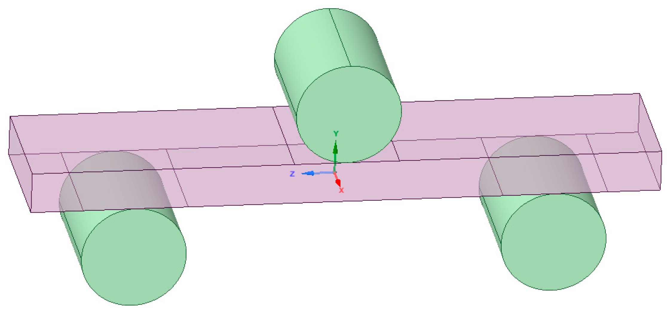
Three-point bending tests were simulated for the flexural behavior of LOM-printed woven jute/PLA biocomposite laminates. The properties evaluated include the flexural stress–strain relationship, flexural strength, and flexural modulus. SpaceClaim was used to represent the geometry of the flexural test specimen, much like in the tensile simulation.
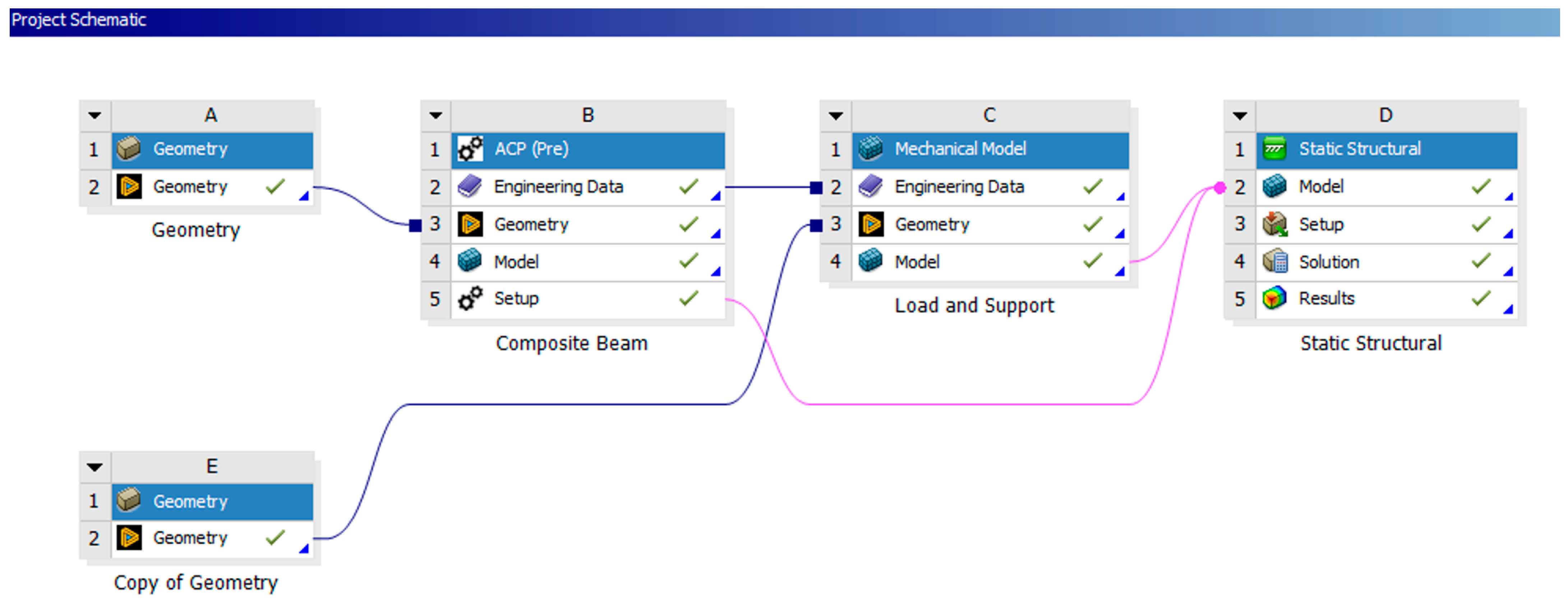
The schematic workflow and transformation process for the flexural property simulation carried out in the ANSYS Workbench are shown in Figure 9. In Section A, the geometry of the jute/PLA composite for the three-point bending simulation was created, as shown in Figure 10. Section B introduced the ACP module for the composite laminate stack-up, providing engineering data for jute/PLA biocomposites as outlined in Table 2. Within Section B, a single layer of the composite beam was isolated to create the necessary ply stack-ups. A duplicate of this geometry had previously been generated in Section E for the addition of load and supports following the preparation of the composite layer stack-up. In Section B, the authors utilized the space claim ANSYS geometry option to separate one layer from the geometry, then employed the modeling ply option to create the 12-ply and 16-ply laminates.
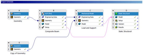
Figure 9.
Project schematic for the flexural FEA simulation of LOM-printed woven jute/PLA biocomposite laminates.
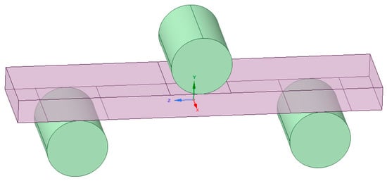
Figure 10.
Geometrical model of LOM-printed woven jute/PLA biocomposite laminates in three-point bending.

Table 2.
Input Woven Jute/PLA Biocomposite Laminates’ Properties for Flexural Simulation.
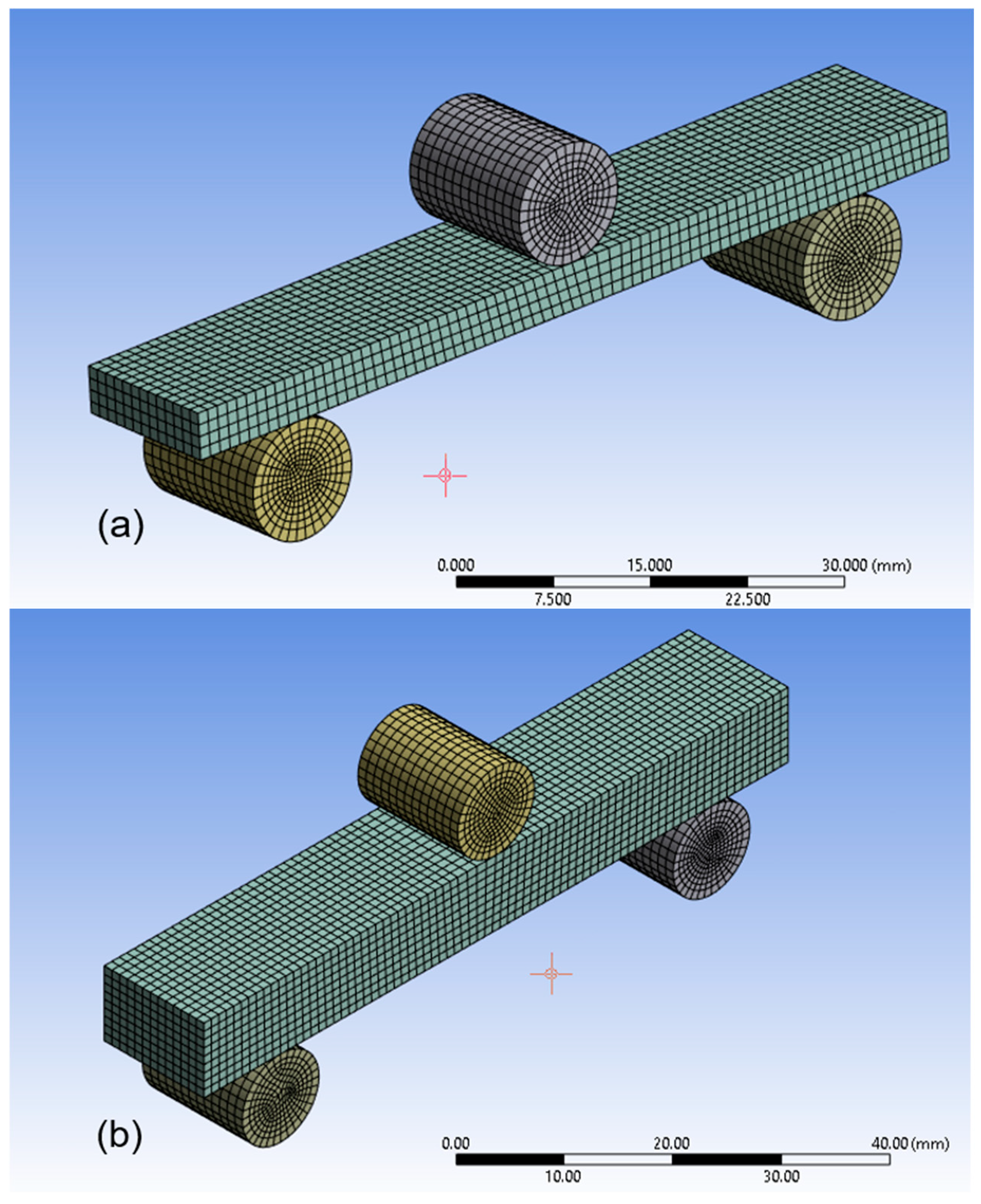
Once the jute/PLA biocomposite laminates are completed in Section B, Section E transferred load and support properties only to Section C (load and supports) to assign the material properties for the load and support, identified as Carbon steel, 1020 annealed, which is the same as the material of the fixtures used in experiments. The biocomposite beam from Section B and the load and support from Section C were merged in Section D (static structural analysis) to complete the 12-ply and 16-ply biocomposite laminates with load and supports. This approach ensures proper layer stacking and material definitions for both the biocomposite (jute/PLA) and the load and supports (Carbon Steel, 1020). After the biocomposite laminates were stacked, quadratic meshing (higher-order elements) was generated with element sizes from 16 mm to 2 mm for convergence study because linear elements did not capture bending edges effectively. Figure 11a,b show the meshing of 12-ply and 16-ply laminates in three-point bending, respectively.
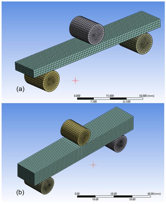
Figure 11.
The meshing of the LOM-printed woven jute/PLA biocomposite laminates in three-point bending: (a) 12-ply, (b) 16-ply.
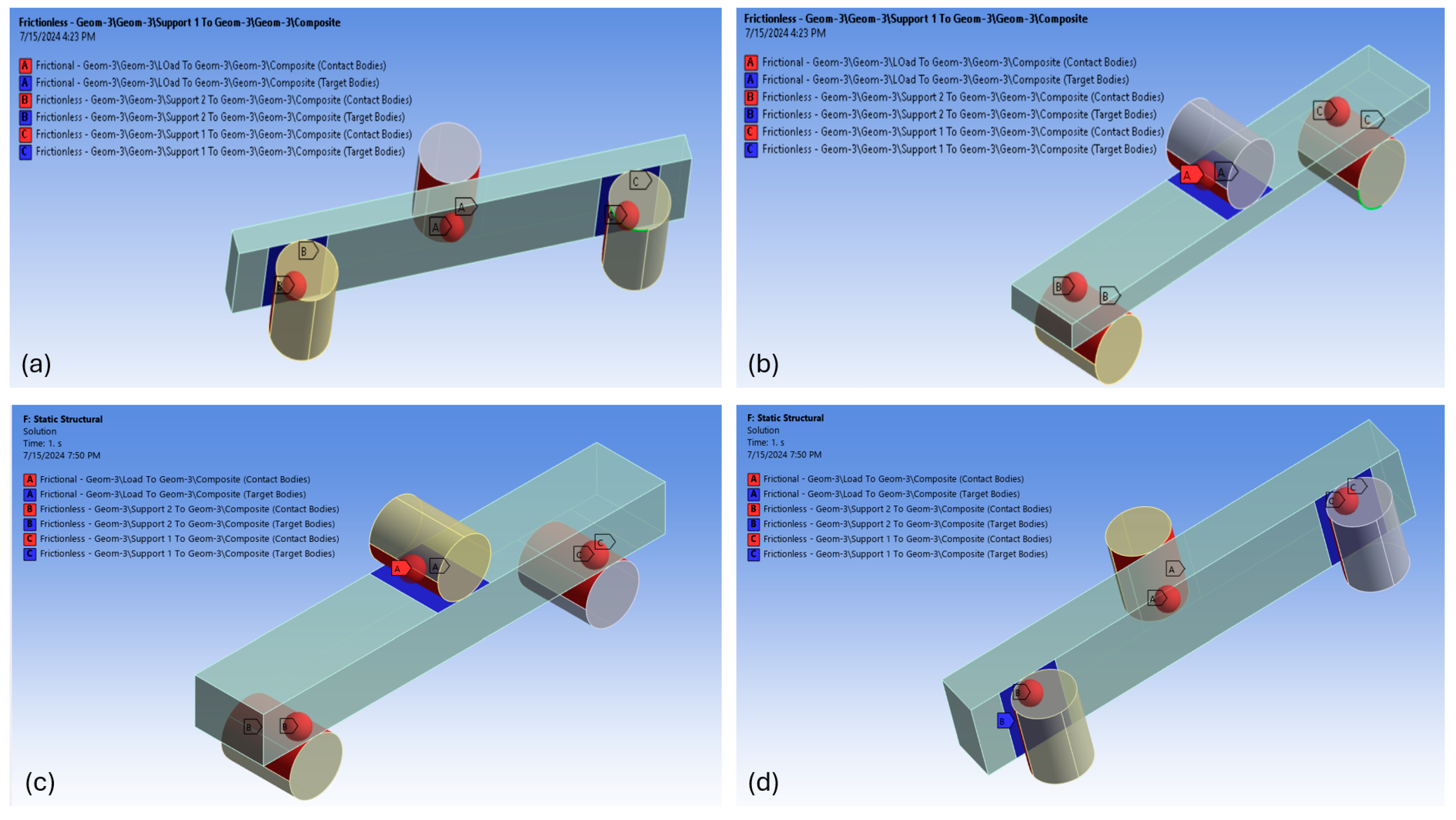
Furthermore, in Section D, the contacts between the load and support and the composite were defined. Frictional contact definitions were used for the load, whereas frictionless contact definitions were used for the composite’s contacts with the supports to maintain their fixed position. Figure 12a–d show the contact definitions for the load and supports with the biocomposite laminate specimen.
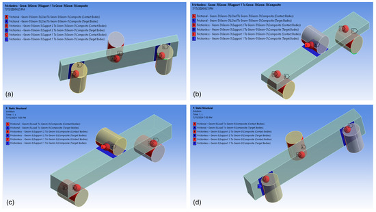
Figure 12.
Contact definition between biocomposite laminates and load with supports: (a,b) 12-ply, (c,d) 16-ply.
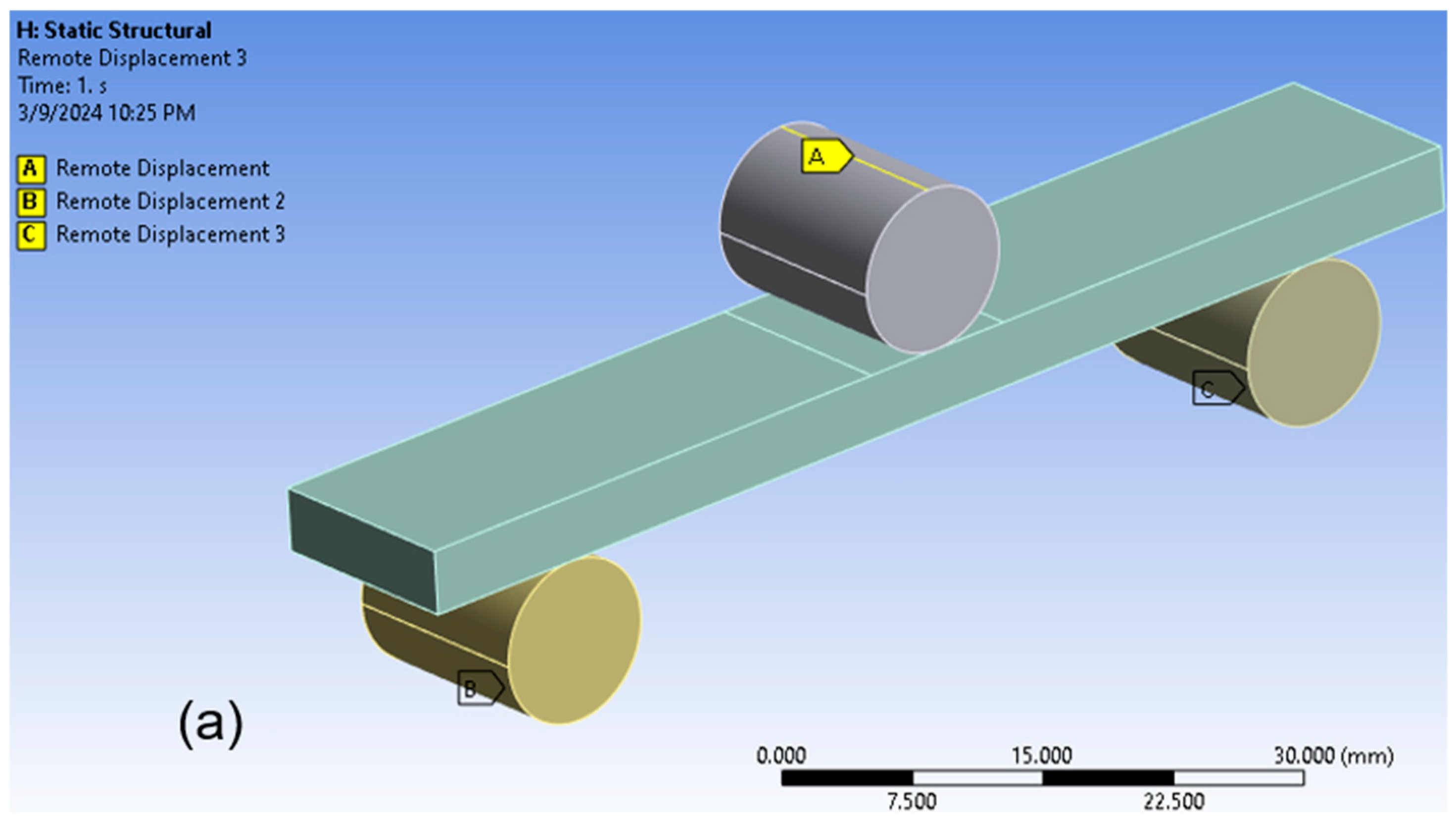
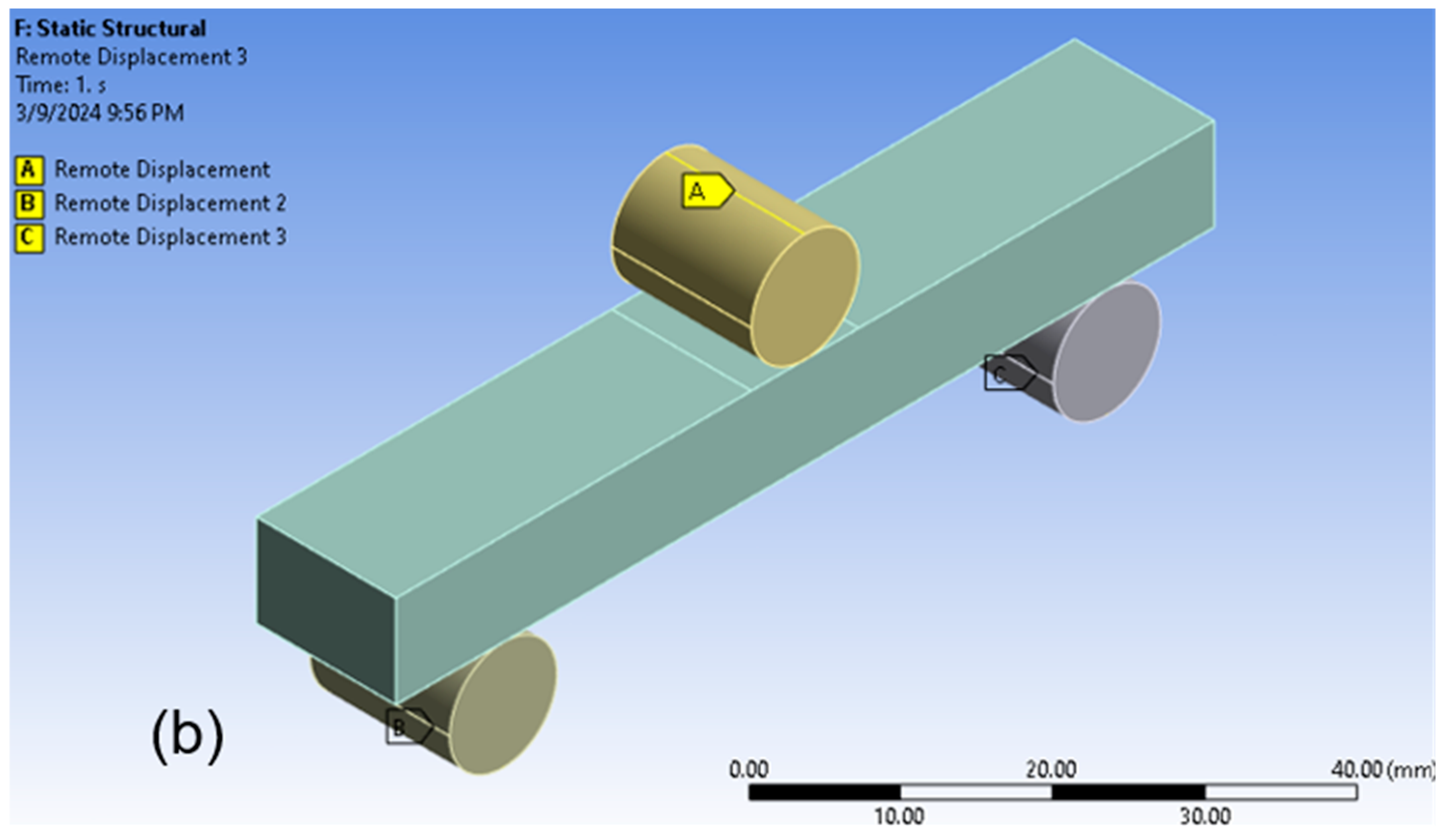
After the contact definitions were set up, the FEA simulation solution for the biocomposite laminates was initiated by implementing remote displacements in the load. Figure 13a,b, respectively, show the remote displacement applied on the load and supports for the 12-ply and 16-ply biocomposite laminates. Experimentally measured midspan displacements were assigned to the load for the 12-ply and 16-ply biocomposite laminates simulations, respectively. No displacements were added to the supports to ensure their fixed position.
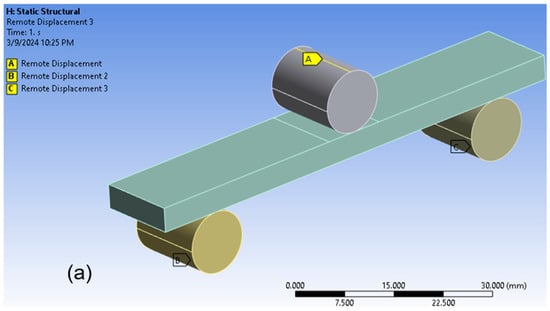
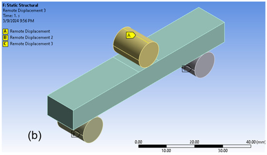
Figure 13.
Remote displacements applied in a loading indentor and two supports: (a) 12-ply, (b) 16-ply.
3. Results and Discussions
In this section, the tensile and flexural properties of the biocomposite laminates measured experimentally are compared with the FEA simulated ones, with detailed discussions.
3.1. Experimental Results
The experimentally measured tensile properties of the five specimens for both six- and eight-ply woven jute/PLA biocomposite laminates are listed in Table 3. The average tensile strengths measured for the six-ply and eight-ply biocomposite laminates were 22.07 MPa and 16.39 MPa, respectively. The eight-ply laminates had a lower tensile strength compared to six-ply laminates. This may be caused by the time and pressure required to properly bond the adjacent plies, which increased as the number of biocomposite laminates increased, which very likely burnt and caused the charring of the biocomposite laminates. The average elastic moduli were 887.27 MPa and 774.07 MPa, respectively. The tensile stress–strain curves are shown in Figure 14. Based on these two figures, it seems that the slopes of both six- and eight-ply test specimens are relatively close to each other, indicating small variances in the elastic moduli of both groups of test specimens. Larger variations can be found in the maximum stress (tensile strength) achieved among each specimen. These results meant unstable mechanical properties were identified among individual test specimens even if they were made via the same process. This problem is also common with most natural fiber-reinforced composites. All tensile test specimens failed due to fiber rupture.

Table 3.
Experimentally Measured Tensile Properties.

Figure 14.
The five tensile stress–strain curves of (a) 6-ply laminates, (b) 8-ply laminates test specimens.
The experimentally measured flexural properties of the five specimens for both 12- and 16-ply woven jute/PLA biocomposite laminates are listed in Table 4. The average flexural strength of the 12-ply and 16-ply biocomposite laminates were 43.11 MPa and 25.82 MPa, respectively. The average flexural moduli were 1.12 GPa and 520.50 MPa, respectively. The flexural stress–strain curves are shown in Figure 15. The same situations regarding flexural stress and strain can be identified from the two figures: similar slopes indicated close values in the measured flexural modulus, while variations were found among the maximum stresses measured. Different strain values were associated with the starting point of the curves in Figure 15b, and this is because of the slight difference in the thickness of each flexural test specimen made. The indentor of the UTM moved downwards from the same starting location but started to press the test specimens at different travel distances. All flexural test specimens failed due to buckling.

Table 4.
Experimentally Measured Flexural Properties.

Figure 15.
The five flexural stress–strain curves of (a) 12-ply laminates, (b) 16-ply laminates test specimens.
3.2. Finite Element Analysis Results
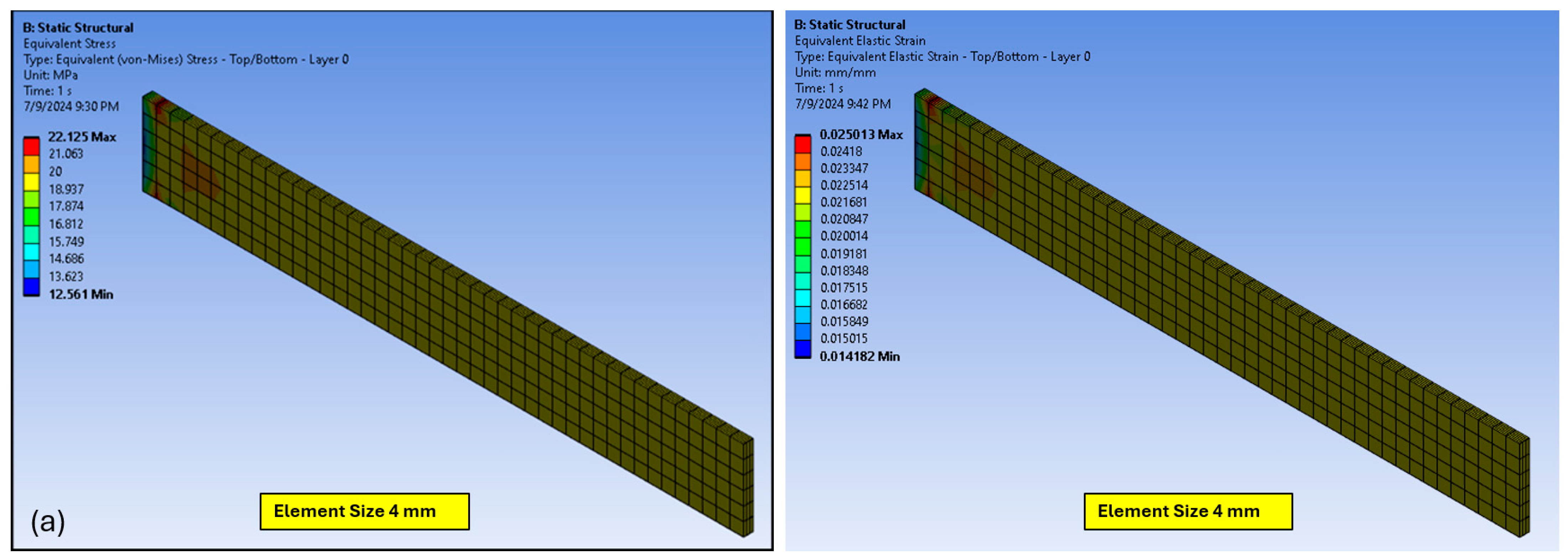
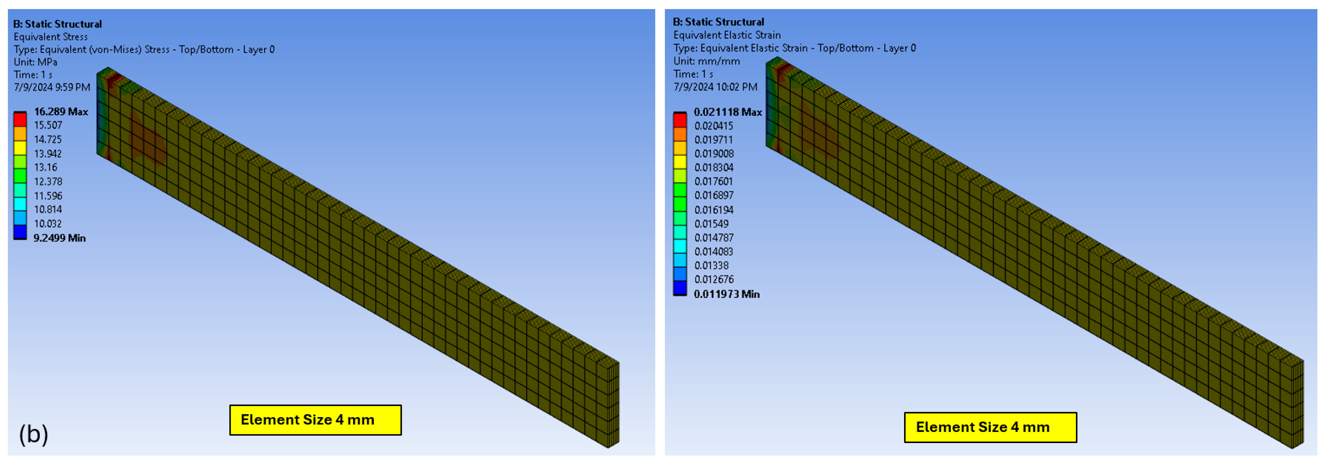
The simulation to calculate the equivalent (von Mises) tensile stress and equivalent elastic strain within the biocomposite specimen was carried out by the finite element solver. This procedure gave important information on the mechanical behavior of the material. Figure 16 displays the distribution of tensile stress and strain produced by the simulation using a 4 mm meshing size. These results demonstrated that the six-ply biocomposite laminates had a simulated tensile strength of 22.13 MPa and a maximum tensile strain of 2.50%, while the eight-ply biocomposite laminates had a simulated tensile strength of 16.29 MPa and a maximum tensile strain of 2.11%.
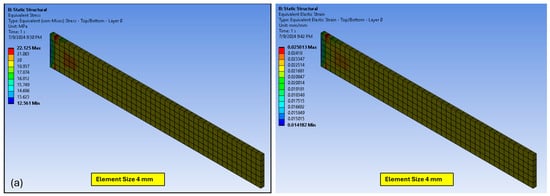
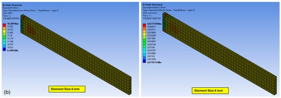
Figure 16.
Tensile stress (left) and strain (right) FEA simulation results of LOM-printed woven jute/PLA biocomposite laminates: (a) 6-ply; (b) 8-ply.
The mesh convergence study of the tensile test simulations was performed using element sizes from 32 mm to 4 mm for both six- and eight-ply laminates, and the results are shown in Figure 17. In this figure, the tensile strength and strain are the two control parameters, and it can be seen that as the element sizes decreased, the simulated results of both stress and strain of six- and eight-ply laminates were relatively stable with little changes in values. When the value of interest varies randomly and by a small amount in both directions, the model can be said to have converged [29].

Figure 17.
Mesh convergence study of LOM-printed woven jute/PLA biocomposite laminates tensile tests: (a) tensile stress, (b) tensile strain.
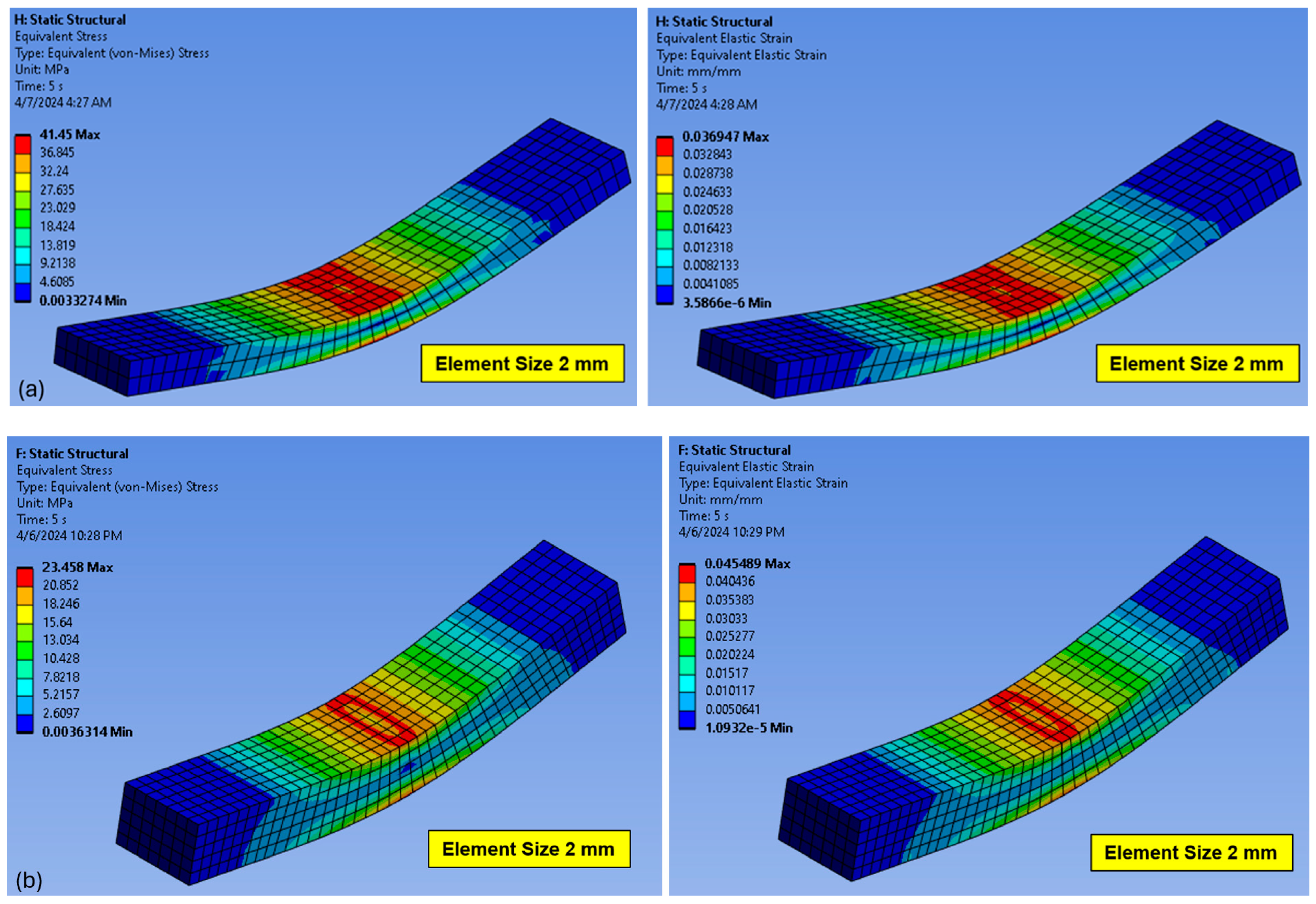
For the flexural test, the flexural stress and strain were calculated using the above-mentioned midspan displacements and two fixed supports. Figure 18 displays the resulting equivalent flexural stress and strain distributions with a meshing size of 2 mm within the biocomposite laminates, respectively. The 12-ply biocomposite laminates had a simulated maximum flexural stress of 41.45 MPa and a maximum flexural strain of 3.69%, while the 16-ply biocomposite laminates had a simulated maximum flexural stress of 23.46 MPa and a maximum flexural strain of 4.55%.
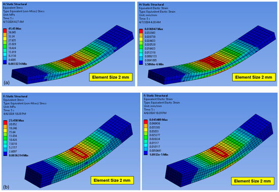
Figure 18.
Flexural stress (left) and strain (right) FEA simulation of LOM-printed woven jute/PLA biocomposite laminates: (a) 12-ply, (b) 16-ply.
The mesh convergence study of the flexural test simulations was performed using element sizes from 16 mm to 2 mm for both 12- and 16-ply laminates, and the results are shown in Figure 19. In this figure, the flexural stress and strain are the two control parameters, and it can be seen that as the element sizes decreased, the simulated results of both stress and strain of 12- and 16-ply laminates had a trend to increase and approach the experimentally measured values. The element size had a small impact on the simulated values for 12-ply laminates, while the impact on 16-ply was larger. This may be because the initial mesh size of 16 mm was way too large for the 16-ply laminates.

Figure 19.
Mesh convergence study of LOM-printed woven jute/PLA biocomposite laminates flexural tests: (a) flexural stress, (b) flexural strain.
4. Conclusions
In this work, an in-house built LOM 3D printer was developed for additive manufacturing jute/PLA biocomposite laminates. Tensile and flexural properties were measured experimentally and then simulated using the ANSYS Mechanical Composite PrepPost (ACP) module for laminated structures.
Table 5 illustrates the matching of results between experimental measurements and FEA simulation. All experimentally measured values are very close to their corresponding FEA simulated ones, within a maximum difference of 9.18%. Such results indicate that the ANSYS software can be successfully utilized to simulate the mechanical properties of the woven jute/PLA biocomposite laminates.

Table 5.
Comparison of the Experimental Data and FEA Simulated Data.
The relationship between the experimentally measured results and FEA simulations can be attributed to several key factors as described below:
- Material properties: Successful modeling and simulation depend on accurate material characteristics. Engineering data of the woven jute/PLA biocomposite laminates in this study were assigned from the measured mechanical properties of the woven jute/PLA biocomposite laminates made. PLA polymers have tensile strengths from 39.9 MPa to 52.5 MPa and flexural strengths from 52.5 MPa to 65.9 MPa [30]. Surprisingly, experimentally measured values are much smaller compared to these ranges. This may be because of two reasons: First, the mechanical properties of the woven jute fabric used in this study had low measured values due to the low fiber densities of the fabric. Secondly, the infusion process of PLA powder and the woven jute fiber was not complete; even the fabric surfaces were completely covered by PLA powder. The measured strengths in both tensile and flexural tests were inversely related to the number of plies in the test specimens. This is because as the number of biocomposite laminates increased, the time and pressure required to properly bond the adjacent plies increased, which very likely burnt and caused the charring of the biocomposite laminates. The measured strain of 16-ply flexural specimens increased with the increased number of plies, even if the loaded flexural stress is much smaller compared to 12-ply specimens; this is due to a similar reason: as too many plies are included in the specimens, it was much more difficult for the heat to penetrate all the layers and therefore caused poor adjacent layer bonding situations at mid-thickness locations;
- Geometry and layering: Layer-by-layer construction is a component of LOM printing. Ensuring that the FEA model accurately represents the layer-by-layer laminate geometry guarantees that the simulation closely resembles the real process. Tensile properties of woven jute/PLA biocomposite laminates with six and eight plies were accurately guaranteed, with precise material properties for every layer. Similarly, for the woven jute/PLA biocomposite laminate flexural specimen, 12 and 16 plies were taken into consideration. Layer thickness and orientation were appropriately established for every layer. By appropriately applying ply stack-up and orientation, FEA simulation was able to provide the intended experimental result;
- Loading and boundary conditions: It is essential to replicate the loading conditions used in the experimental procedures. To guarantee that the tensile simulation closely resembles the experimental result, the authors appropriately characterized the external pressures, limitations, and interactions that the biocomposite laminates encounter. For the three-point bending test simulation, realistic contact definitions and remote displacements of the specimen were used in the FEA simulation;
- Meshing: For effectively capturing the features of the model, proper meshing in critical areas is needed. Additionally, proper element aspect ratios help in accurately representing the structural response. The authors performed a meshing convergence study from large element sizes until the smallest element size provided by the ANSYS 2024 R1 version had been achieved for each application, and the simulation results indicated that such meshing size was small enough to achieve reasonable accuracy.
In conclusion, FEA simulations can help with design optimization and performance prediction by precisely predicting the mechanical behaviors of biocomposite laminate materials. One limitation of the reported study is that the fracture behavior of the material is not involved in the model, which means such FEA simulation cannot predict the failure modes of the biocomposite laminates. This study, as an exemplary case study, provides valuable insights and guidance for future studies and attempts to model and simulate the mechanical behaviors of biocomposite laminates made via a new process.
Author Contributions
Conceptualization, L.J.; methodology, L.J., J.P., S.R.S. and X.P.; software, S.R.S.; validation, L.J., S.R.S., M.S.I. and B.P.; formal analysis, L.J. and S.R.S.; investigation, S.R.S., L.J., M.S.I. and B.P.; resources, L.J. and S.R.S.; data curation, L.J. and S.R.S.; writing—original draft preparation, S.R.S. and L.J.; writing—review and editing, S.R.S., L.J. and J.P.; visualization, S.R.S.; supervision, L.J.; project administration, L.J.; funding acquisition, L.J. All authors have read and agreed to the published version of the manuscript.
Funding
This research was funded by the National Science Foundation (NSF) of the United States grant number 1909699.
Data Availability Statement
Research data supporting reported results can be obtained via requests sent to the corresponding author.
Conflicts of Interest
The authors declare no conflict of interest.
References
- Maiti, S.; Islam, M.R.; Uddin, M.A.; Afroj, S.; Eichhorn, S.J.; Karim, N. Sustainable Fiber-Reinforced Composites: A Review. Adv. Sustain. Syst. 2022, 6, 2200258. [Google Scholar] [CrossRef]
- Gioia, C.; Giacobazzi, G.; Vannini, M.; Totaro, G.; Sisti, L.; Colonna, M.; Marchese, P.; Celli, A. End of Life of Biodegradable Plastics: Composting versus Re/Upcycling. Logo Blackwellopen 2021, 14, 4167–4175. [Google Scholar] [CrossRef] [PubMed]
- Beldzki, A.K.; Faruk, O.; Sperber, V.E. Cars from Bio-Fibres. Macromol. Mater. Eng. 2006, 291, 449–457. [Google Scholar] [CrossRef]
- Fu, Z.; Suo, B.; Yun, R.; Lu, Y.; Wang, H.; Qi, S.; JIang, S.; Lu, Y.; Matejka, V. Development of eco-friendly brake friction composites containing flax fibers. J. Reinf. Plast. Compos. 2012, 31, 681–689. [Google Scholar] [CrossRef]
- Liu, K.; Takagi, H.; Yang, Z. Evaluation of transverse conductivity of Manila hemp fiber in solid region using theoretical method and finite element method. Mater. Des. 2011, 32, 4589. [Google Scholar] [CrossRef]
- Wang, H.; Lei, Y.; Wang, J.S.; Qin, Q.H.; Xiao, Y. Theoretical and computational modeling of clustering effect on effective thermal conductivity of cement composites filled with natural hemp fibers. J. Compos. Mater. 2016, 50, 1509–1521. [Google Scholar] [CrossRef]
- Wang, H.; Qin, Q.H.; Xiao, Y. Special n-sided Voronoi fiber/matrix elements for clustering thermal effect in natural-hemp-fiber-filled cement composites. Int. J. Heat Mass Transf. 2016, 92, 228–235. [Google Scholar] [CrossRef]
- Bringing Natural Fibre Composite Innovations to the Sports Industry. Bcomp, 2023. Available online: https://www.jeccomposites.com/news/by-jec/bringing-natural-fibre-composite-innovations-to-the-sports-industry/ (accessed on 23 February 2024).
- Salfino, C. Stop the Synthetics: Consumers Want Technical, Natural Fiber Activewear 28 May 2020. [Online]. Available online: https://sourcingjournal.com/topics/lifestyle-monitor/activewear-natural-fiber-cotton-synthetics-npd-champion-212703/ (accessed on 23 February 2024).
- Schlüchter, A. The Use of Natural Fiber for Functional Sportswear Established Itself. SAZ Sport, 2 April 2020. [Online]. Available online: https://www.sazsport.de/markt-sortimente/sports-fashion-by-saz/the-use-of-natural-fiber-for-functional-sportswear-established-itself-2531953.html (accessed on 23 February 2024).
- Shen, L.; Haufe, J.; Patel, M.K. Product Overview and Market Projection of Emerging Bio-Based Plastics; Universiteit Utrecht: Utrecht, The Netherlands, 2009. [Google Scholar]
- Plackett, D.; Andersen, T.L.; Batsberg Pedersen, W.; Nielsen, L. Biodegradable composites based on L-polylactide and jute fibres. Compos. Sci. Technol. 2003, 63, 1287–1296. [Google Scholar] [CrossRef]
- Liu, L.; Yu, J.; Cheng, L.; Yang, X. Biodegradability of poly(-butylene succinate) (PBS) composite reinforced with jute fibre. Polym. Degrad. Stab. 2009, 94, 90–94. [Google Scholar] [CrossRef]
- Islam, M.S.; Oickering, K.L.; Foreman, N.J. Influence of alkali treatment on the interfacial and physico-mechanical properties of industrial hemp fibre reinforced polylactic acid composites. Compos. Part A 2010, 41, 596–603. [Google Scholar] [CrossRef]
- Curtis, P.T.; Bishop, S.M. An assessment of the potential of woven carbon fibre-reinforced plastics for high performance applications. Composites 1984, 15, 259–265. [Google Scholar] [CrossRef]
- Le Page, B.H.; Guild, F.J.; Ogin, S.L.; Smith, P.A. Finite element simulation of woven fabric composites. Compos. Part A 2004, 35, 861–872. [Google Scholar] [CrossRef]
- Song, Y.S.; Lee, J.T.; Ji, D.S.; Kim, M.W.; Lee, S.H.; Youn, J.R. Viscoelastic and thermal behavior of woven hemp fiber reinforced poly(lactic acid) composites. Compos. Part B 2012, 43, 856–860. [Google Scholar] [CrossRef]
- Baghaei, B.; Skrifvars, M.; Berglin, L. Characterization of thermoplastic natural fibre composites made from woven hybrid yarn prepregs with different weave pattern. Compos. Part A 2015, 76, 154–161. [Google Scholar] [CrossRef]
- Kandola, B.K.; Mistik, S.I.; Pornwannachai, W.; Anand, S.C. Natural fibre-reinforced thermoplastic composites from woven-nonwoven textile preforms: Mechanical and fire performance study. Compos. Part B 2018, 153, 456–464. [Google Scholar] [CrossRef]
- Jiang, L.; Walczyk, D.F.; McIntyre, G.; Bucinell, R.; Li, B. Bioresin infused then cured mycelium-based sandwich-structure biocomposites: Resin transfer molding (RTM) process, flexural properties, and simulation. J. Clean. Prod. 2019, 207, 123–135. [Google Scholar] [CrossRef]
- Jiang, L.; Walczyk, D.F.; McIntyre, G.; Bucinell, R.; Tudryn, G. Manufacturing of biocomposite sandwich structures using mycelium-bound cores and preforms. J. Manuf. Process. 2017, 28, 50–59. [Google Scholar] [CrossRef]
- Christian, S.J. Natural fibre-reinforced noncementitious composites (biocomposites). In Nonconventional and Vernacular Construction Materials: Characterisation, Properties and Applications; Harris, K.A., Sharma, B., Eds.; Elsevier Ltd.: Pittsburgh, PA, USA, 2016; pp. 111–126. [Google Scholar]
- Jiang, X.; Luo, Y.; Tian, X.; Huang, D.; Reddy, N.; Yang, Y. Chemical Structure of Poly(Lactic Acid). In Poly(Lactic Acid): Synthesis, Structures, Properties, Processing, and Applications; John Wiley and Sons: Hoboken, NJ, USA, 2010; pp. 69–82. [Google Scholar]
- Casalini, T.; Rossi, F.; Castrovinci, A.; Perale, G. A Perspective on Polylactic Acid-Based Polymers Use for Nanoparticles Synthesis and Applications. Front. Bioeng. Biotechnol. 2019, 7, 259. [Google Scholar] [CrossRef]
- Gehrke, F.; Frey, S.; Jani, M. The Best PLA Filaments of 2023—Buyer’s Guide. All3DP, 7 December 2023. [Online]. Available online: https://all3dp.com/1/best-pla-filament/#:~:text=PLA%20is%20the%20most%20popular,and%20has%20outstanding%20material%20properties (accessed on 23 March 2024).
- Nagarajan, V.; Mohanty, A.K.; Misra, M. Perspective on Polylactic Acid (PLA) based Sustainable Materials for Durable Applications: Focus on Toughness and Heat Resistance. ACS Sustain. Chem. Eng. 2016, 4, 2899–2916. [Google Scholar] [CrossRef]
- Kaczmare, H.; Nowicki, M.; Vuković-Kwiatkowska, I. Crosslinked blends of poly(lactic acid) and polyacrylates: AFM, DSC and XRD studies. J. Polym. Res. 2013, 20, 91. [Google Scholar] [CrossRef]
- Jiang, L.; Shahriar, S.; Grady, T.; Peng, X. Woven Natural Fiber-Reinforced PLA Polymers 3D Printed through a Laminated Object Manufacturing Process. In Proceedings of the SAMPE 2023 Proceedings, Seattle, WA, USA, 17–20 April 2023. [Google Scholar]
- Langnau, L. Avoiding singularities in FEA boundary conditions. 3D CAD World, 6 February 2021. [Online]. Available online: https://www.3dcadworld.com/avoiding-singularities-in-fea-boundary-conditions/ (accessed on 31 May 2024).
- Gao, G.; Xu, F.; Xu, J.; Liu, Z. Study of Material Color Influences on Mechanical Characteristics of Fused Deposition Modeling Parts. Materials 2022, 15, 7039. [Google Scholar] [CrossRef]
Disclaimer/Publisher’s Note: The statements, opinions and data contained in all publications are solely those of the individual author(s) and contributor(s) and not of MDPI and/or the editor(s). MDPI and/or the editor(s) disclaim responsibility for any injury to people or property resulting from any ideas, methods, instructions or products referred to in the content. |
© 2024 by the authors. Licensee MDPI, Basel, Switzerland. This article is an open access article distributed under the terms and conditions of the Creative Commons Attribution (CC BY) license (https://creativecommons.org/licenses/by/4.0/).

