Article

Processing and Analysis of Hybrid Fiber-Reinforced Polyamide Composite Structures Made by Fused Granular Fabrication and Automated Tape Laying

1
Fraunhofer Institute for Microstructure of Materials and Systems IMWS, Walter-Hülse-Straße 1, 06120 Halle (Saale), Germany
2
Fraunhofer Institute for Machine Tools and Forming Technology IWU, Reichenhainer Straße 88, 09126 Chemnitz, Germany
*
Author to whom correspondence should be addressed.
J. Manuf. Mater. Process. 2024, 8(1), 25; https://doi.org/10.3390/jmmp8010025
Submission received: 10 December 2023 / Revised: 21 January 2024 / Accepted: 22 January 2024 / Published: 1 February 2024
(This article belongs to the Topic Advanced Composites Manufacturing and Plastics Processing)

Abstract

:
Fused granular fabrication (FGF) is a large format additive manufacturing (LFAM) technology and focuses on cost-effective granulate-based manufacturing by eliminating the need for semifinished filaments. This allows a faster production time and a broader range of usable materials for tailored composites. In this study, the mechanical and morphological properties of FGF test structures made of polyamid 6 reinforced with 40% of short carbon fibers were investigated. For this purpose, FGF test structures with three different parameter settings were produced. The FGF printed structures show generally significant anisotropic mechanical characteristics, caused by the layer-by-layer building process. To enhance the mechanical properties and reduce the anisotropic behavior of FGF structures, continuous unidirectional fiber-reinforced tapes (UD tapes), employing automated tape laying (ATL), were subsequently applied. Thus, a significant improvement in the flexural stiffness and strength of the manufactured FGF structures was observed by hybridization with 60% glass fiber-reinforced polyamide 6 UD tapes. Since the effectiveness of UD-tape reinforcement depends mainly on the quality of the bond between the UD tape and the FGF structure, the surface quality of the FGF structure, the interface morphology, and the tape-laying process parameters were investigated.

1. Introduction

In recent decades, additive manufacturing (AM) based on the targeted deposition of a polymer melt has focused on the production of small-format components with very high surface quality and optimal geometric brilliance [1]. The fused filament fabrication (FFF) printing systems used are typically based on filament processing with typical filament diameters of 1.75–2.85 mm and allow extrusion rates of up to 6000 mm/min or build rates of 100–480 g/h, depending on the printed object and the type of filament used [2]. However, these filament-based printers usually have small printing space of max. approximately 0.5 m × 0.5 m × 0.5 m and printing rates of 20 cm3/h [3]. As a result, the requirement for larger component volumes, an associated larger construction space, and an increase in printing speed was derived [4,5]. This led to a new term for this type of printing technology, large format additive manufacturing (LFAM), which, however, has not yet been able to establish itself consistently in the industry. The aim of LFAM is to significantly reduce costs to produce larger components more quickly [6].
Fused granular fabrication (FGF) is a special technology within the framework of LFAM, which focuses on granulate or pellet-based manufacturing processes [7]. In comparison to FFF, this procedure can reduce costs by eliminating the need for semifinished filaments, since, for example, the costs for a filament compared to granules are in a ratio of around 10:1 [8]. Moreover, the use of adapted extruders with significantly larger discharge nozzles is possible. This means that production times can be reduced by a factor of up to 200 [9]. Further advantages also lie in the use of a significantly broader range of materials, since all industrially usable thermoplastic polymers are available in the form of granules. These can also be adapted to the respective requirements using fibers, particles, and additives and thus compounded into precisely fitting composite materials with adjustable material properties [10]. This also includes recycled materials from other processing methods, e.g., composite manufacturing, as recently also reported for FFF processes [11,12].
FGF printing processes can be described as young in relation to additive manufacturing processes and have several specific features in the quality of the components produced and in relation to the rheological behavior of the granules in the extrusion process. Transferring the experience from classic extrusion technology is only possible to a limited extent, as systems with movable print heads have limitations in terms of weight and screw length, which play a rather subordinate role in stationary machines. For this reason, several studies have been carried out for a variety of materials (unreinforced/reinforced) to investigate the influence of processing parameters on rheological behavior and glass transition temperature [13,14,15,16]. The degradation behavior also plays a role that needs to be considered. However, due to the reduced screw lengths, shorter residence times of the material are to be expected and thus also reduced damage/degradation of the polymers. Regarding the mechanical properties of the printed components, as with FFF-manufactured structures, there is a clear anisotropy with respect to the layers in the Z-axis [17]. This is further increased when using fiber-reinforced material [18]. In addition to conventional synthetic reinforcing fibers, natural fibers are also being used to increase the mechanical properties of the resulting parts [19]. Furthermore, the quality of the surface and the geometry of components manufactured using FGF is significantly worse than components manufactured using FFF due to the nozzle size and the material quantities deposited. This requires postprocessing steps such as simple milling or more complex processes such as grinding, filling, polishing, and painting [20]. Another solution described in the literature is printing with two differently fine printing nozzles [21].
A promising strategy for improving the mechanical properties of components from the FGF process is the subsequent or simultaneously application of continuously fiber-reinforced filaments or tapes [22,23]. In comparison to continuously fiber-reinforced filaments, higher fiber volume proportions up to 40–50 vol.-% and the associated significantly higher strength and stiffness can be achieved by using continuously fiber-reinforced tapes. The term tape laying generally refers to the automated, direction- and position-variable placement of unidirectional fiber-reinforced thermoplastic tapes (UD tapes) on flat or curved substrates [24]. Thus, local reinforcements or fiber placement according to the load path have already been implemented for many different applications [25]. In particular, 3D tape laying enables targeted reinforcement of the components in accordance with the load path [26]. Typically, the UD tapes are additively processed in layers to form thin-walled, shell-shaped composite structures. This requires a so-called laying head, with which the UD tapes are heated, laid down, and trimmed. The geometry of the later component is dictated by the substrate, onto which the previously melted UD tapes are applied under light contact pressure during the deposition process.
The current state of the art is represented here by the technologies of automated tape laying (ATL) and automated fiber placement (AFP), which were developed in the aerospace industry and are currently finding their way into a wide variety of industries [27]. In the ATL process, UD tapes are unwound from a spool by a storage unit, heated to processing temperature, then placed on a tool contour with a defined contact pressure and finally cut off at the end of the laying path. After a layer of tape has been deposited, the storage unit is realigned, and the next layer of tape can be deposited. Typical laying speeds are approximately 1 m/s [28]. In this way, the laminate is built up step by step according to a given individual layer and laminate definition. Depending on the feeding of the UD tapes, unassembled from a reel or preassembled from a cassette, a distinction is made between single-stage and two-stage or dual systems, as a combination of both process options. This technology is currently mainly used to produce load-resistant lightweight structures with adapted fiber orientation in the aviation industry [29].
A major disadvantage of the current ATL systems is, on the one hand, their size and the uneconomical way of working compared to the processing of conventional semifinished textile products. In addition, tape laying in curved paths is not easily possible with ATL technology. For this reason, the AFP technology was developed, which enables, for example, the shaping of radii or the fiber-friendly design of hole edges and openings [30]. The AFP depositing unit divides the tape into several individual strands of around 10 mm width before depositing it, which means that the fiber path can also be set in a defined manner over certain radii and deposited individually [31]. However, the laying speed is reduced compared to the ATL method.
To partially overcome the previous mentioned disadvantages of ATL, a very compact innovative ATL system, F3-Compositor, with reduced weight of the moving machine parts using a six-axis robot for 3D tape laying, has been recently developed and applied in this work. The innovative approach of the F3-Compositor combines the high-speed tape deposition at a constant laying speed of up to 2 m/s with high reproducibility and material efficiency [32]. The tape-laying head with an integrated heat source based on a hydrogen–oxygen gas mixture enables the heat energy to be targeted in just the right amount and place required for the tape consolidation, thus avoiding unwanted large heat-affected areas. This technology represents an optimal complement to the FGF technology and can therefore be used for the production of hybrid 3D printed components with local fiber reinforcement and significantly improved mechanical properties.

2. Materials and Methods

2.1. Fiber-Reinforced Polyamide Composite Materials

The fiber-reinforced polyamide material used for the FGF process was a short carbon fiber-reinforced polyamide 6 compound (PA6/CF40, AKROMID® B3 ICF 40 black 5020) produced by AKRO-PLASTIC GmbH (Niederzissen, Germany). This material contains 40% recycled content and was used in the supplied granular form. A continuous glass fiber-reinforced polyamide 6 (PA6/GF60-UD, Celstran® CFR-TP PA6-GF60) supplied from TICONA GmbH (Sulzbach, Germany) was used for the tape-laying process in the form of tapes with a width of 3 mm and a thickness of 0.3 mm. Both materials were dried at 80 °C for 4 h prior to processing. The main properties of the used materials derived from the manufacturer’s data sheets are summarized in Table 1.

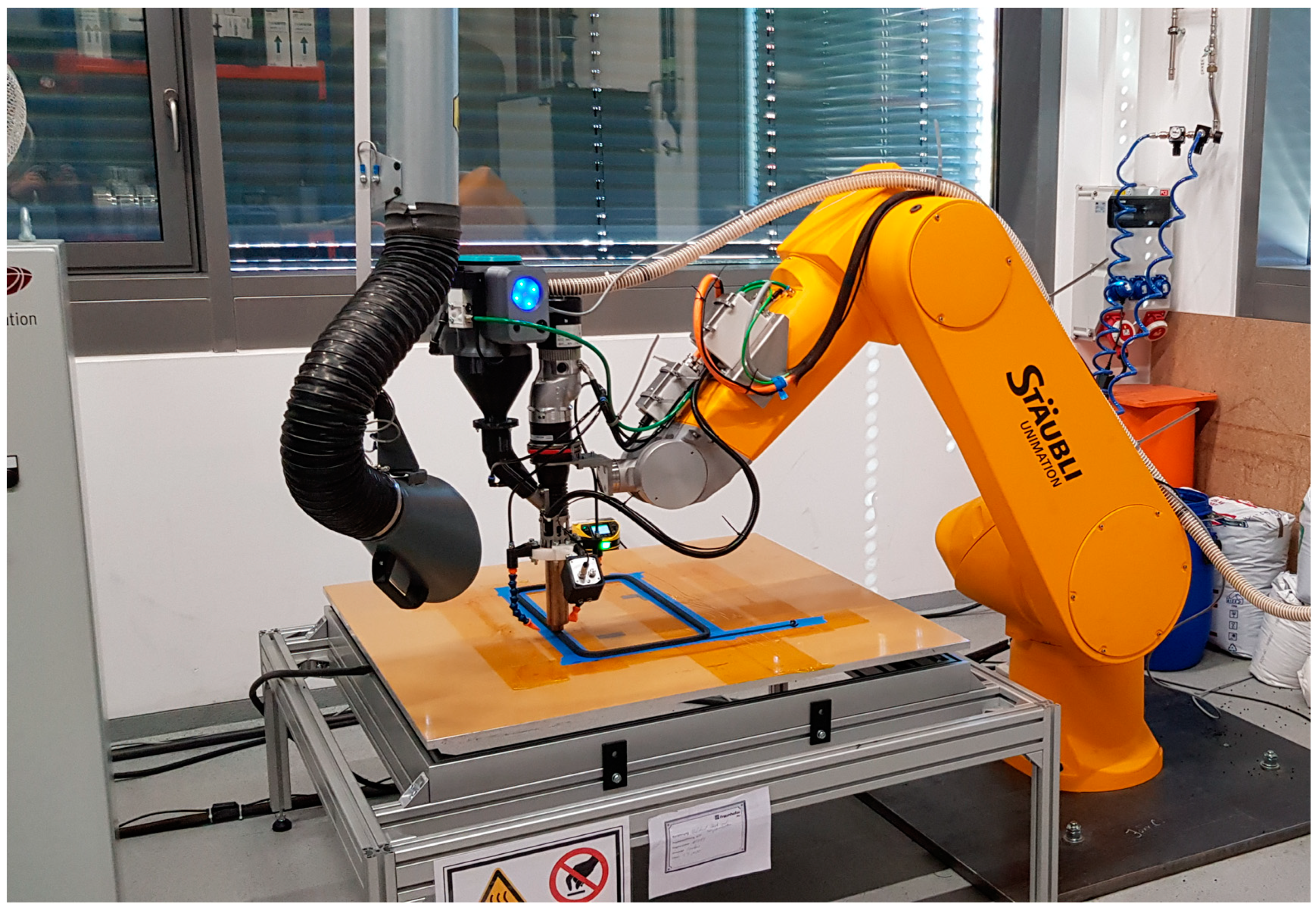
2.2. Fused Granular Fabrication

The used FGF technology, shown in Figure 1, consists of an extrusion unit with a mass output of up to 5 kg/h, a nozzle set with diameters of 1, 1.5, 3, and 6 mm, and integrated sensors (thermal camera µ-Epsilon TIM640). The extrusion unit was adapted to an industrial six-axis robot (Stäubli, RX160) with Siemens Sinumerik NC control for three-dimensional processing. A melt temperature of 280 °C was set for the printing process. A heatable aluminum plate with an area 1 × 1 m2 was used as a print bed, and the temperature of the heating system was set to 120 °C. The resulting substrate temperatures were measured in the range 70–75 °C.
With this setup, specific test structures in the shape of a rib structure with 6 parallel walls and 1 perpendicular wall were printed with a one-way printing path direction, as shown in Figure 2. After printing, the structure walls were marked with letters from A to G according to the printing order and cut into 7 single plates (150 × 305 mm) that were used as blanks for manufacturing the test samples. The test structures were printed with three different parameter setups; the resulting wall thicknesses are given in Table 2.

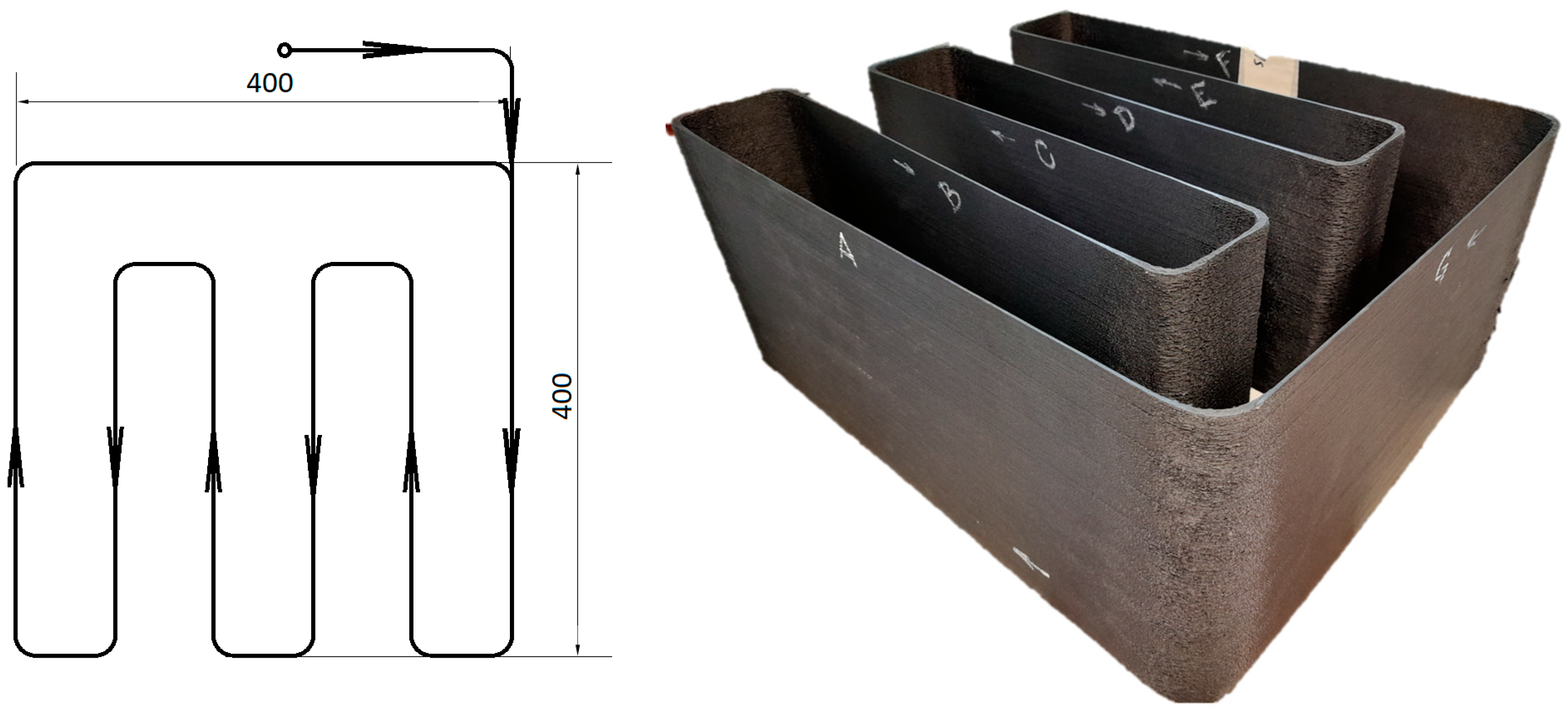
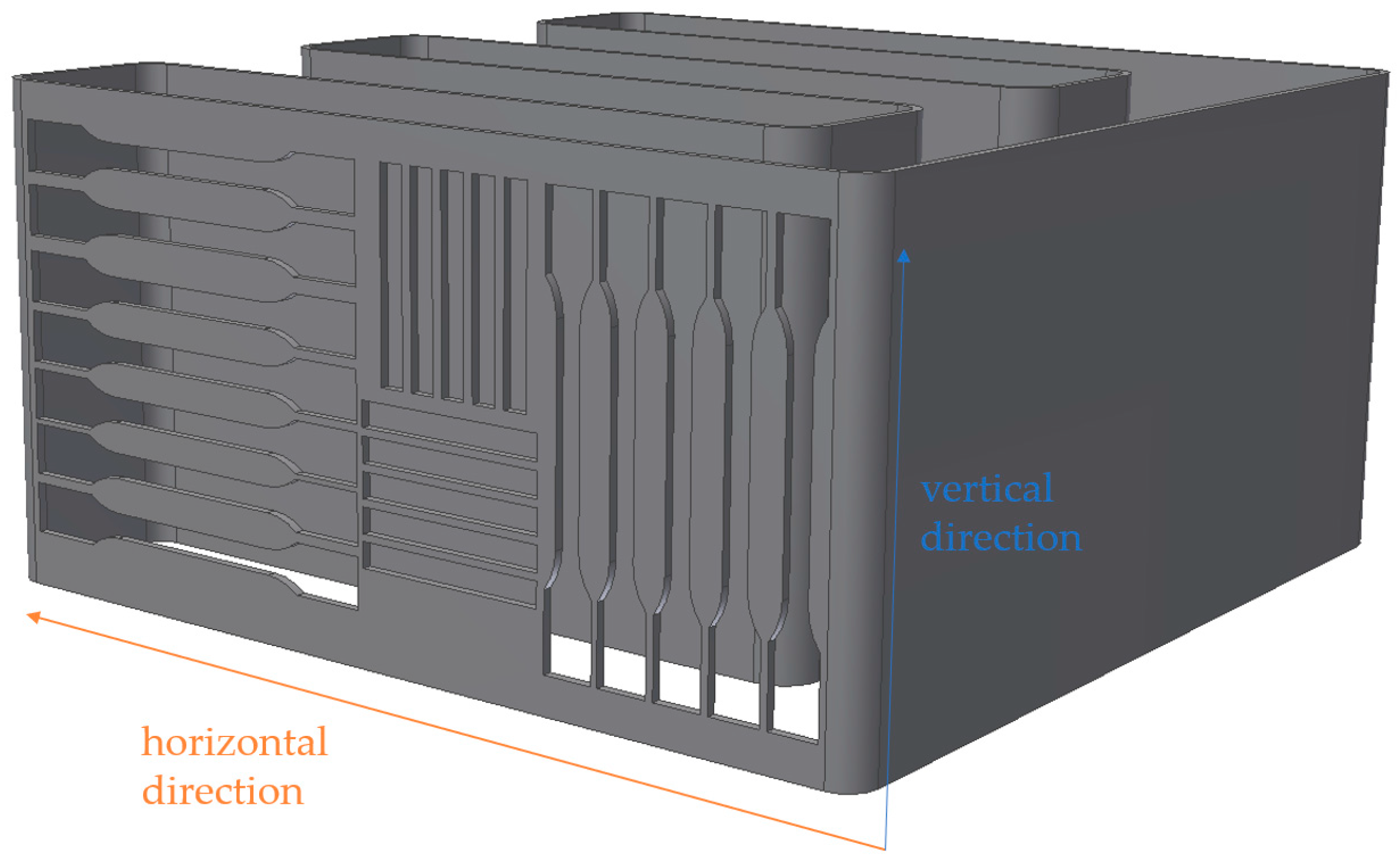
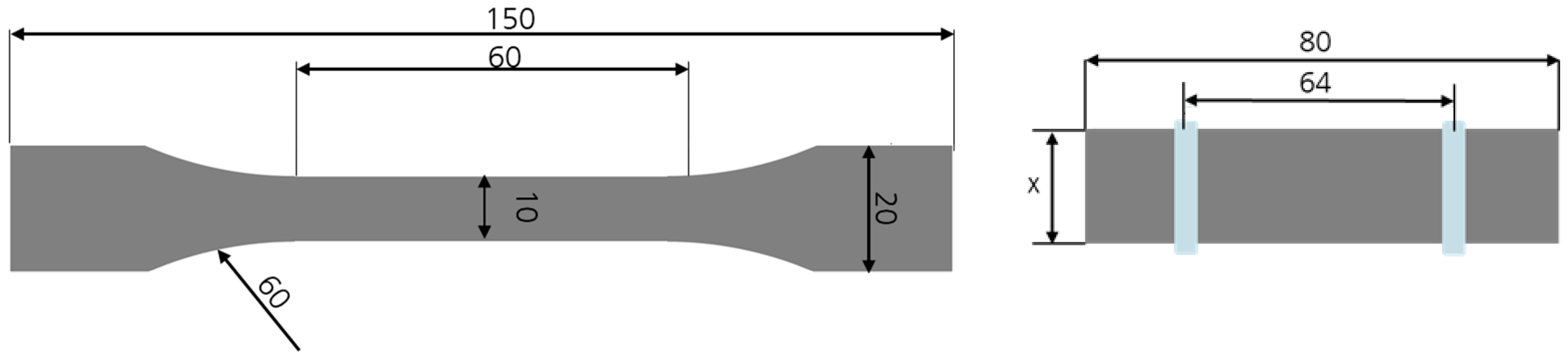
2.3. Preparation of Fused Granular Fabrication Test Specimen

The test samples for the mechanical analysis were manufactured by water jet cutting from the processed FGF plates in horizontal and vertical directions (see Figure 3). Apart from the difference in the extrusion width of the three plate types and therefore the thickness of the test specimen, the dimensions used for tensile and bending test samples stayed the same and are shown in Figure 4. The width x of the bending test specimen was selected based on the plate thickness following DIN EN ISO 178:2019 [33]. The resulting widths for FGF-1, 2, and 3 were 25, 10, and 15 mm, respectively. The 80 mm sample length and the 64 mm length of the support span were constant, as shown in Figure 4. Accelerated conditioning according to DIN EN ISO 1110 was performed prior to testing [34]. At 70 °C and 62% relative humidity, the weight gain was controlled regularly to validate the conditioning duration based on sample thickness.

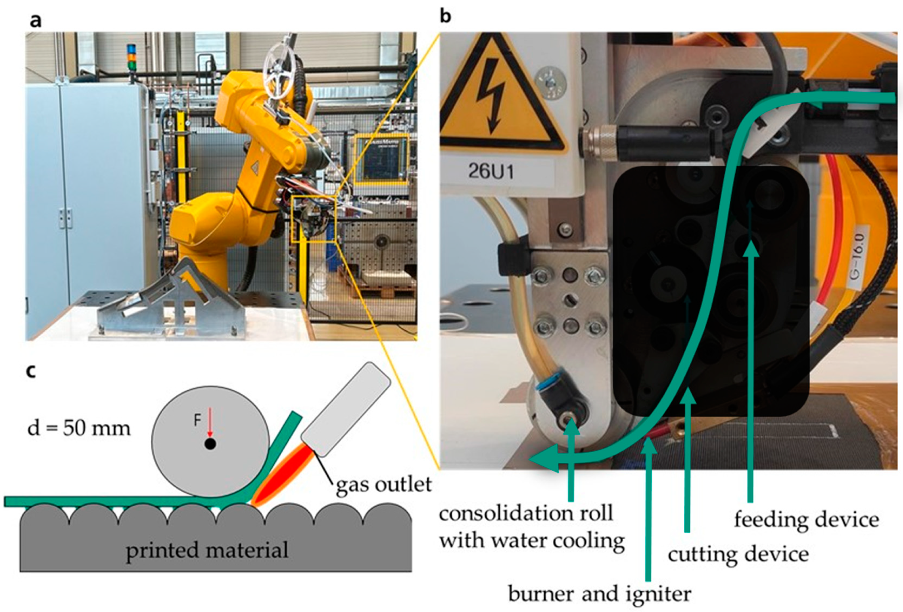
2.4. Automated Tape Laying

Processing of the PA6/GF60-UD materials was performed on the different FGF plates with an automated tape-laying unit (F3-Compositor, ASH Automation Steeg und Hoffmeyer GmbH) with a maximum layup speed of 250 mm/s, as shown in Figure 5. In this technology, the UD tape is fed with a constant velocity and locally heated above its melting temperature just before deposition. This is achieved by an open-flame heating mechanism, consisting of a hydrogen and oxygen gas mixture. The gas mixture can also be diluted with normal air. At the deposition point, the UD tape is compacted and consolidated in situ by a roll with a predetermined force. Additionally, heat is extracted by water cooling of the roll. This leads to solidification and the tape is cut at the end of a track. The processing parameters used are given in Table 3. For each FGF plate, two configurations with the UD-tape direction parallel or perpendicular to the printing direction were processed (see Figure 6 for illustration).

2.5. Preparation of Automated Tape-Laying Test Specimen

The bending test samples for the mechanical analysis of the automated tape-laying process were also manufactured by water jet cutting parallel to the tape direction from the processed hybrid test plates in accordance with DIN EN ISO 178:2019 (see Figure 4 (right) for illustration) [33]. According to the varied thickness due to the tape laying, the width x of the samples was modified to 26.6, 13.8, and 17 mm.

2.6. Morphological Analysis

For the detailed examination of print quality, fiber alignment and the bonding between the UD tapes and the printed FGF material, test specimens 15 × 15 mm in size were embedded in a clear and low-viscosity epoxy resin with a curing time of 12 h (EpoFix) and polished with a diamond polishing solution to a 0.25 μm finish. Micrographs were taken with an Olympus BX51 optical microscope. Figure 7 shows the schematic illustration of the sectional view where the samples were cut and polished, and the resulting micrograph of these samples. Additionally, a 3D-laser scanning microscope (Keyence VK-X1050) was used to measure surface roughness, which is determined by the geometry of the FGF layer lines. For this, an area of 70 × 10 mm was measured for each FGF plate type. For the density measurement by ethanol immersion, 15 × 15 mm samples for each FGF plate type were prepared using a band saw.

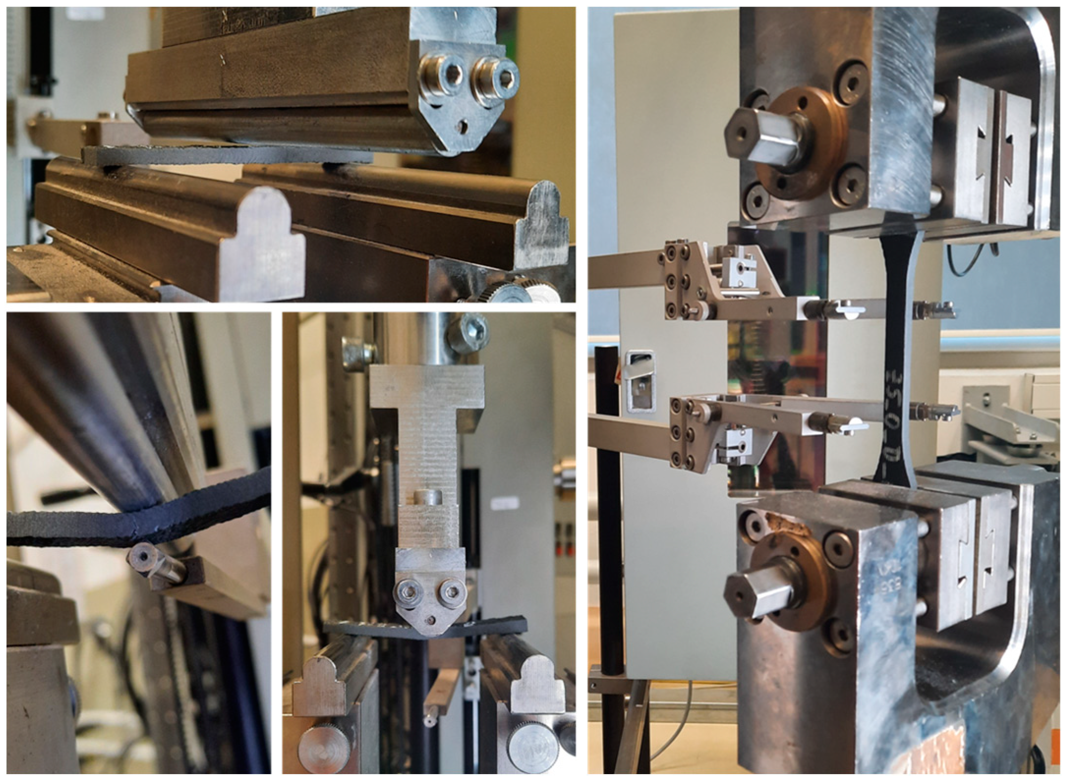
2.7. Mechanical Analysis

Tensile testing according to DIN EN ISO 527 was performed for FGF samples without UD tape, as shown in Figure 8 [35]. In this, a constant test speed of 1 mm/min was used for testing the tensile properties. Three-point bending tests were conducted on the FGF and hybrid test specimens with UD tapes according to DIN EN ISO 178:2019 (see Figure 8) [33]. A Z050 Zwick/Roell testing machine was used for the tensile and three-point bending tests with a load cell of 20 kN. A constant test speed of 2 mm/min was used to determine the flexural modulus, while the rest of the test was conducted at 10 mm/min. The 80 mm sample length and the 64 mm length of the support span always stayed the same. All hybrid samples were tested with the UD tapes on the underside of the samples loaded in tension mode. In the case of the hybrid samples and for the samples without any UD-tape reinforcement, a homogeneous cross-section was assumed for calculating bending stress.

3. Results and Discussion

3.1. Composite Structures by Fused Granular Fabrication

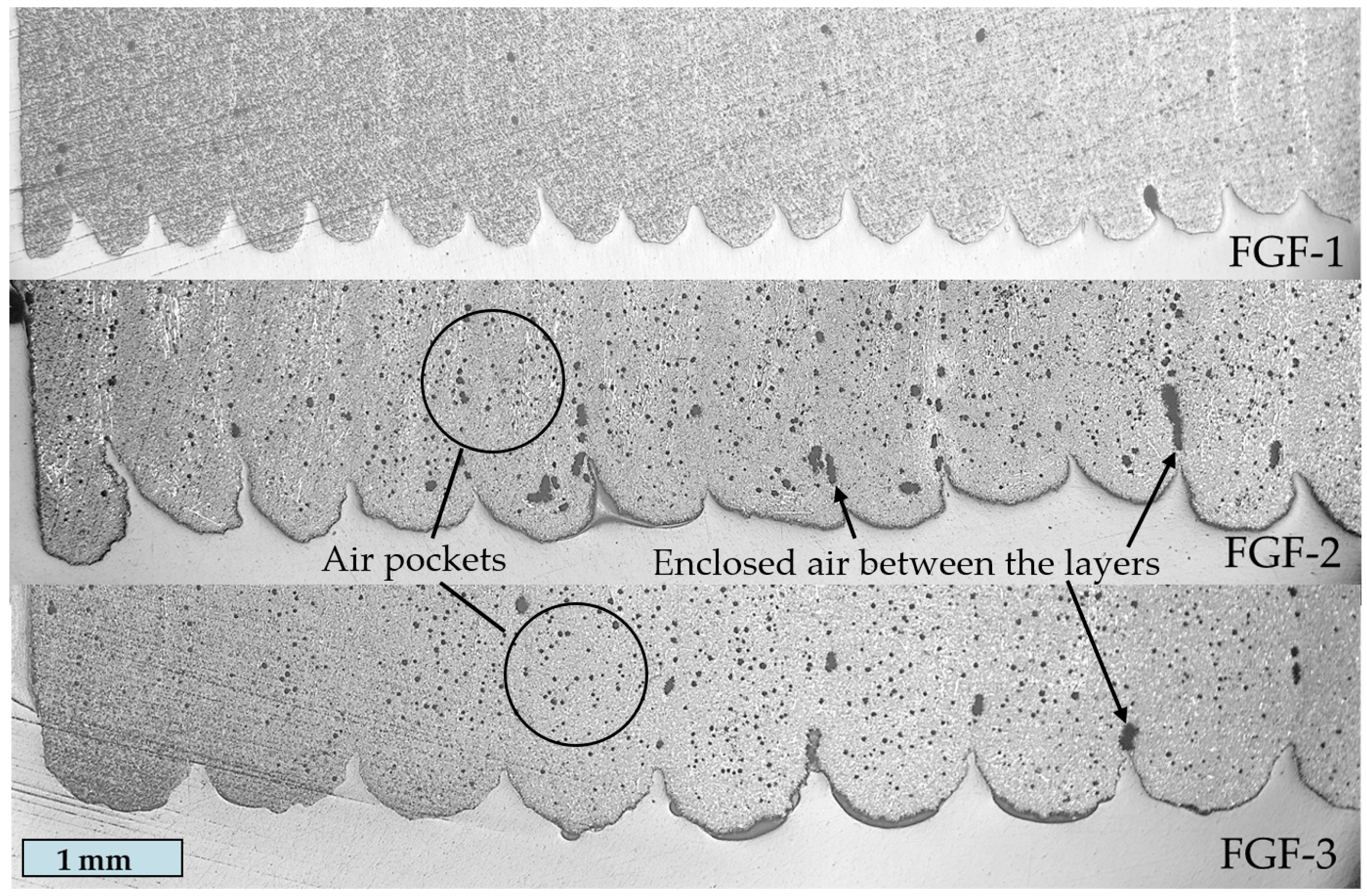
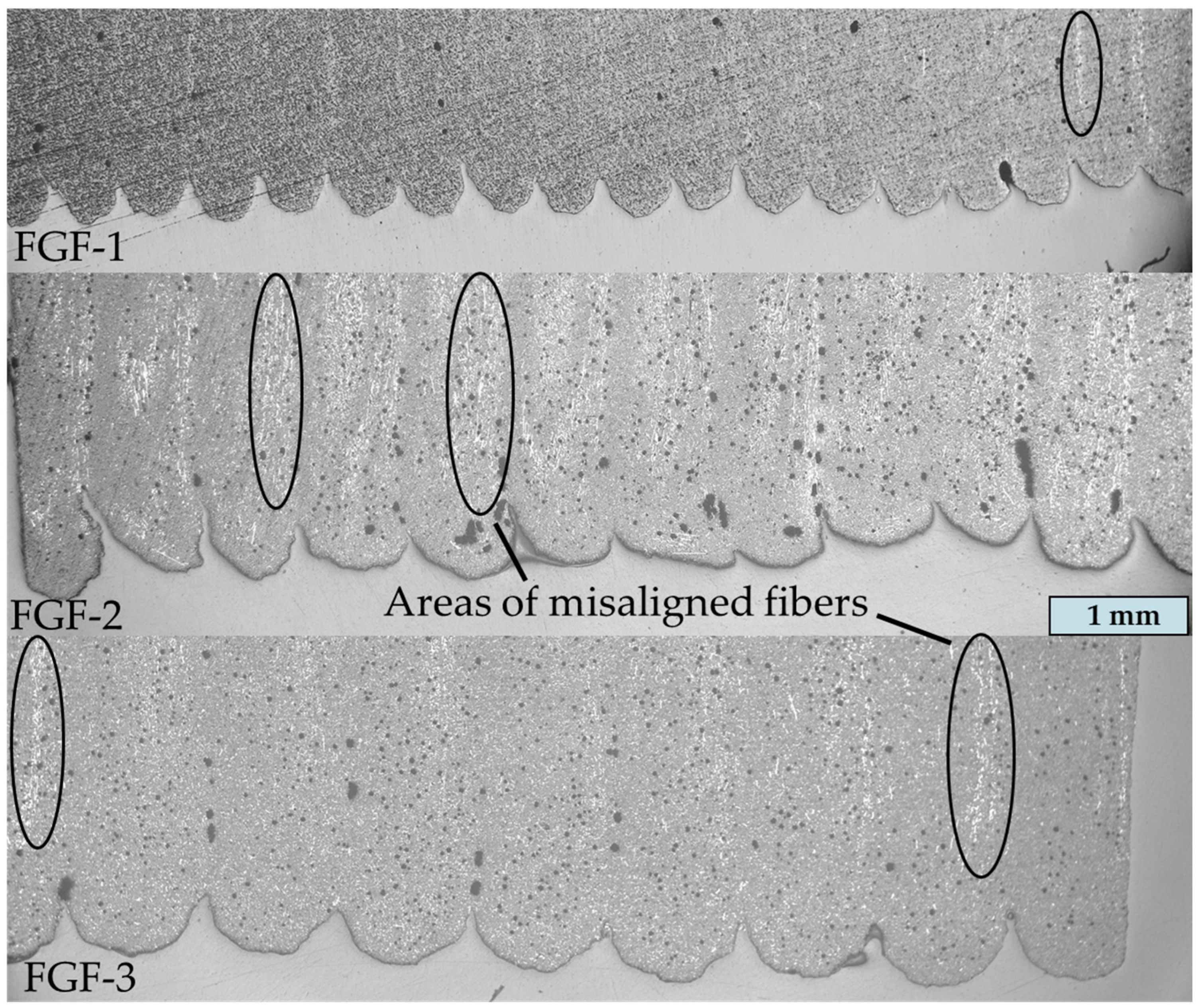
3.1.1. Morphological Analysis

Figure 9 shows a comparison of the micrograph cross-sections of the printed FGF structures. The gray semicircles represent the outer surface edge of the printed structures and the vertical thickness between the layers is referred to as layer height. The geometry of the printed layers is the result of the ratios of the extrusion width and layer height to printing nozzle diameter (Table 2). The bigger ratios of the layer width and height to the nozzle diameter lead to greater layer irregularity and to reduction in the ideal semicircularity in the cross-section of the layers. FGF-2 is the most irregular one and has much enclosed air between the layers. Therefore, FGF-2 is expected to have a reduced bonding quality of the layers. In contrast, FGF-1, with similar layer height, width, and nozzle diameter ratios as FGF-3, has almost no visible air gaps between layers, which is probably related to the higher temperatures of the previous printed layer due to the higher printing speed. FGF-2 and FGF-3 both have a greater density of air pockets than FGF-1. They can be seen as small black circles in Figure 9.
Table 4 shows the measurements of the density and the surface roughness for the three plate types. As expected, FGF-1 has the smallest roughness while Ra for FGF-2 and FGF-3 are equal. The high roughness of FGF-2 is because of the extrusion width to printing nozzle diameter ratio. FGF-1 has the highest density close to the value in the datasheet. The larger number of the air pockets in FGF-2 and FGF-3 are the reason for their decreased density. However, the observed surface roughness values Ra of 63 µm for FGF-1 and 95 µm for FGF-2 and FGF-3 samples are much higher than values reported in the literature for fused deposition modeling test samples with Ra < 50 µm [36]. Significant reduction in surface roughness can be achieved by postprocessing, e.g., by laser polishing [37].

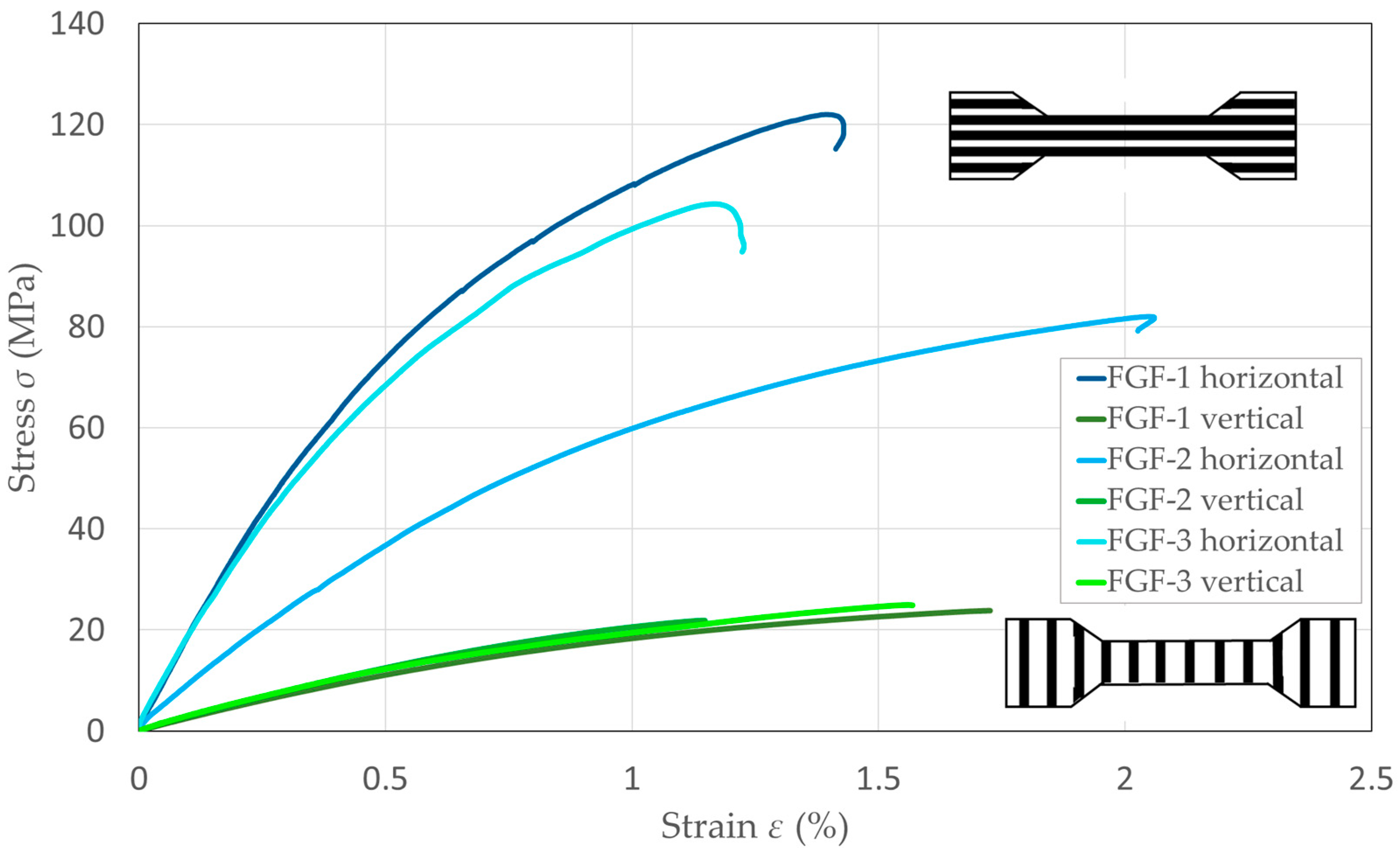
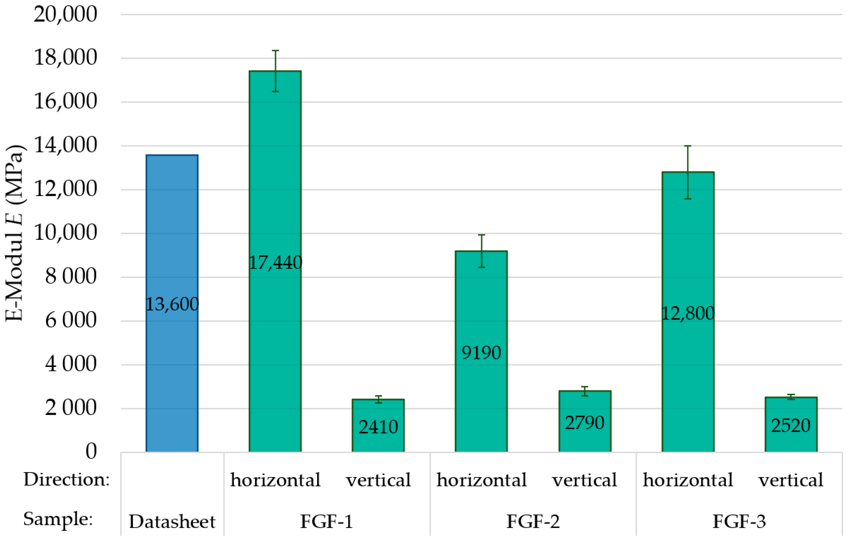
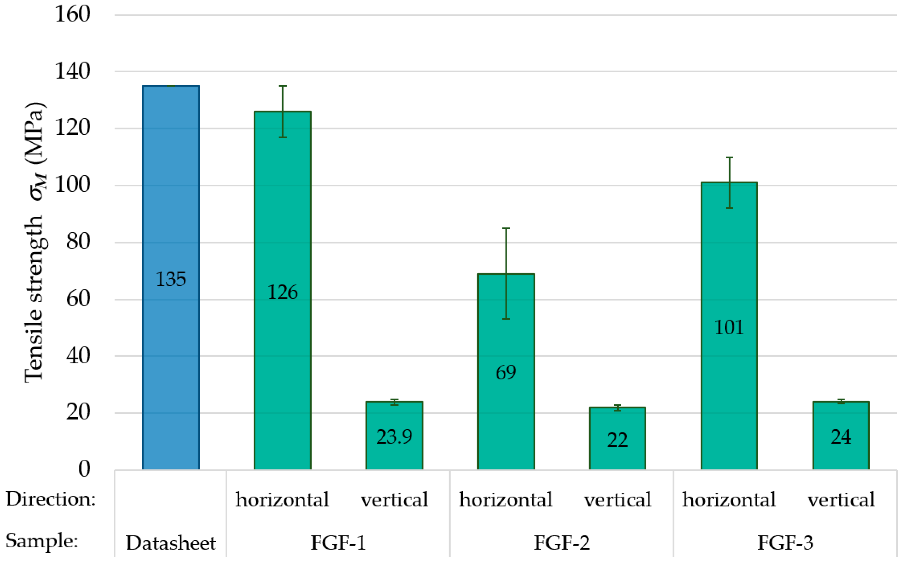
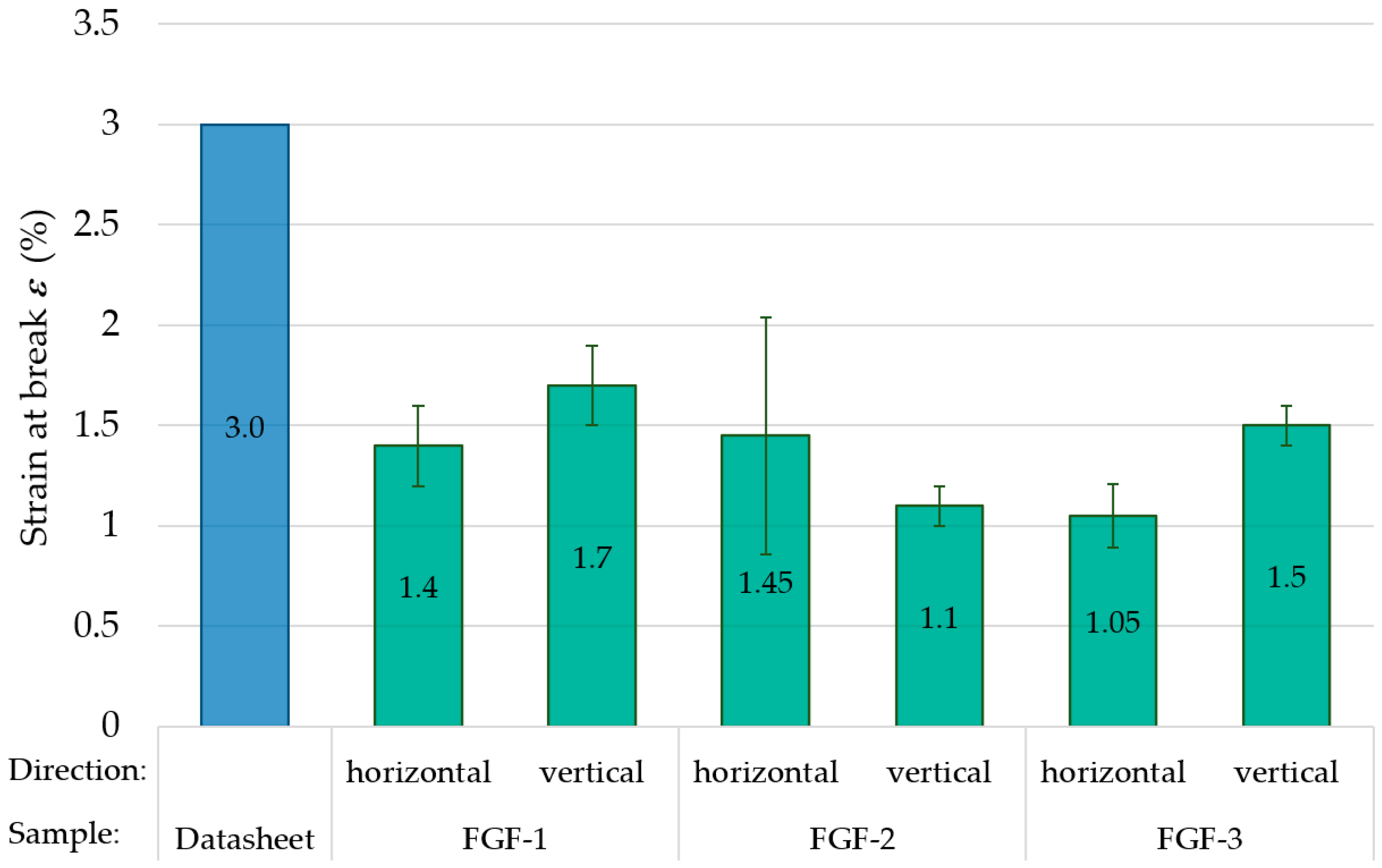
3.1.2. Mechanical Analysis

Depending on the different layer orientation, significant different fracture behavior was observed in the manufactured FGF samples (Figure 10). In tensile and flexural specimens with vertical layer orientation, interlayer fracture always occurred. Samples with horizontal layer orientation broke and created sharp edges. Figure 11 shows the mean stress/strain curves for the FGF test samples obtained during tensile testing. Samples of FGF-2 with horizontal layer configuration have a noticeable difference in modulus of elasticity, which is addressed to their different fiber orientation in the layers. The direction of the fibers directly influences the modulus of elasticity [38].
Because of the high ratio of extrusion width to nozzle diameter, many carbon fibers are not aligned with the printing direction. This can be seen in Figure 12. The fibers should barely be visible when directed out of plane. The areas with a high density of misaligned fibers appear white; in the case of FGF-2, the white areas are much more numerous.
The analysis of the tensile test (Figure 13, Figure 14 and Figure 15) shows that the tensile behavior is strongly dependent not only on test direction (horizontal vs. vertical) but also on the used parameters in manufacturing of the fused granular fabrication test samples, especially for the tensile strength and the elastic modulus of the FGF test samples. The mechanical properties of FGF-3 are similar to prior analysis of the same material using the same fabrication process [39]. The highest value of elastic modulus and tensile strength in the horizontal direction was achieved by sample FGF-1, with 17,440 MPa and 126 MPa, respectively. In this case, it is evident that the mechanical properties of samples in horizontal direction can even exceed the values specified in the data sheet for an injection molded specimen [40]. However, significantly lower tensile strength and elastic modulus values were recorded in the vertical direction, indicating strong anisotropic behavior of the FGF parts. Nevertheless, there were no significant differences in the values between all three types of FGF tested.
The FGF specimens in the horizontal and vertical directions achieved relatively similar values of elongation at break. The FGF-2 samples tended to have a lower elongation at break compared to other tested samples in the vertical direction. The reason could be the irregularity of the layers and the resulting air gaps in between them, which results in strong local differences in the interlayer strength within the same specimen. This explanation is also consistent with the exceptionally high variability in tensile strength and strain of FGF-2. In comparison to the horizontal direction, slightly higher values of elongation at break were measured by FGF-1 and FGF-3 samples in the vertical direction. These results may be in contrast with several studies, where the samples indicated much higher elongation in the layer direction than in the perpendicular direction [39,40]. In contrast, according to another studies, also investigating the tensile properties of the PA6/CF additively manufactured specimens, elongation at break values in the vertical direction were similar or even higher than in the horizontal direction [41,42]. This may suggest a more complex issue in the effects on elongation at break. A possible explanation is high diffusion of the PA6/CF40 matrix molecules between the layers leading to an increased interlaminar strength. Additionally, the significant anisotropy in the stiffness and strength can lead to higher stress concentrations and crack propagation in the samples of the horizontal direction, e.g., at fibers or air pockets, thus resulting in a lower strain at break. However, to the authors’ best knowledge, there are no recent studies addressing this issue in more detail for short-fiber-reinforced FGF samples with respect to different print build-up orientation.

3.2. Hybrid Composite Structures from Fused Granular Fabrication and Automated Tape Laying

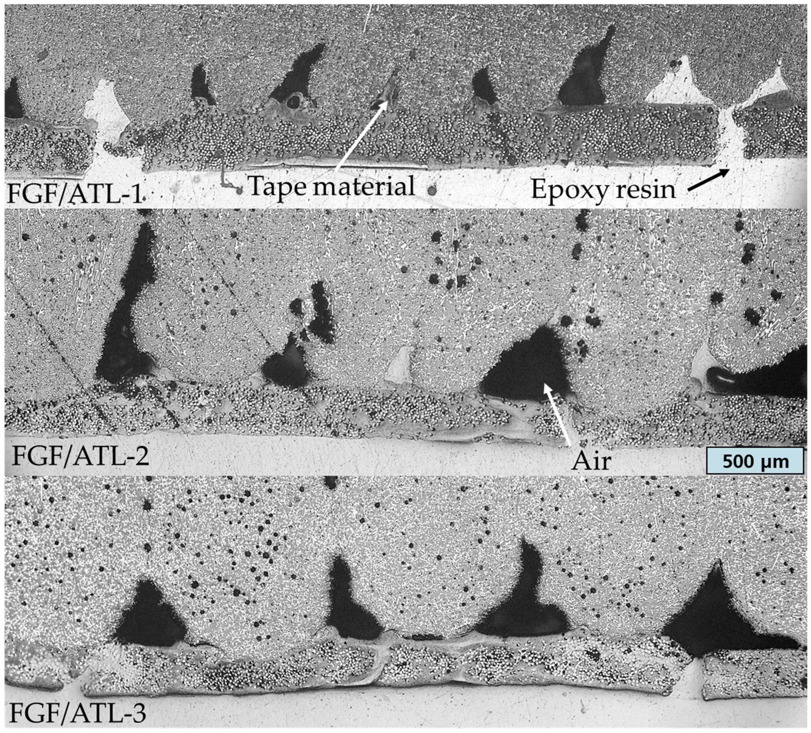
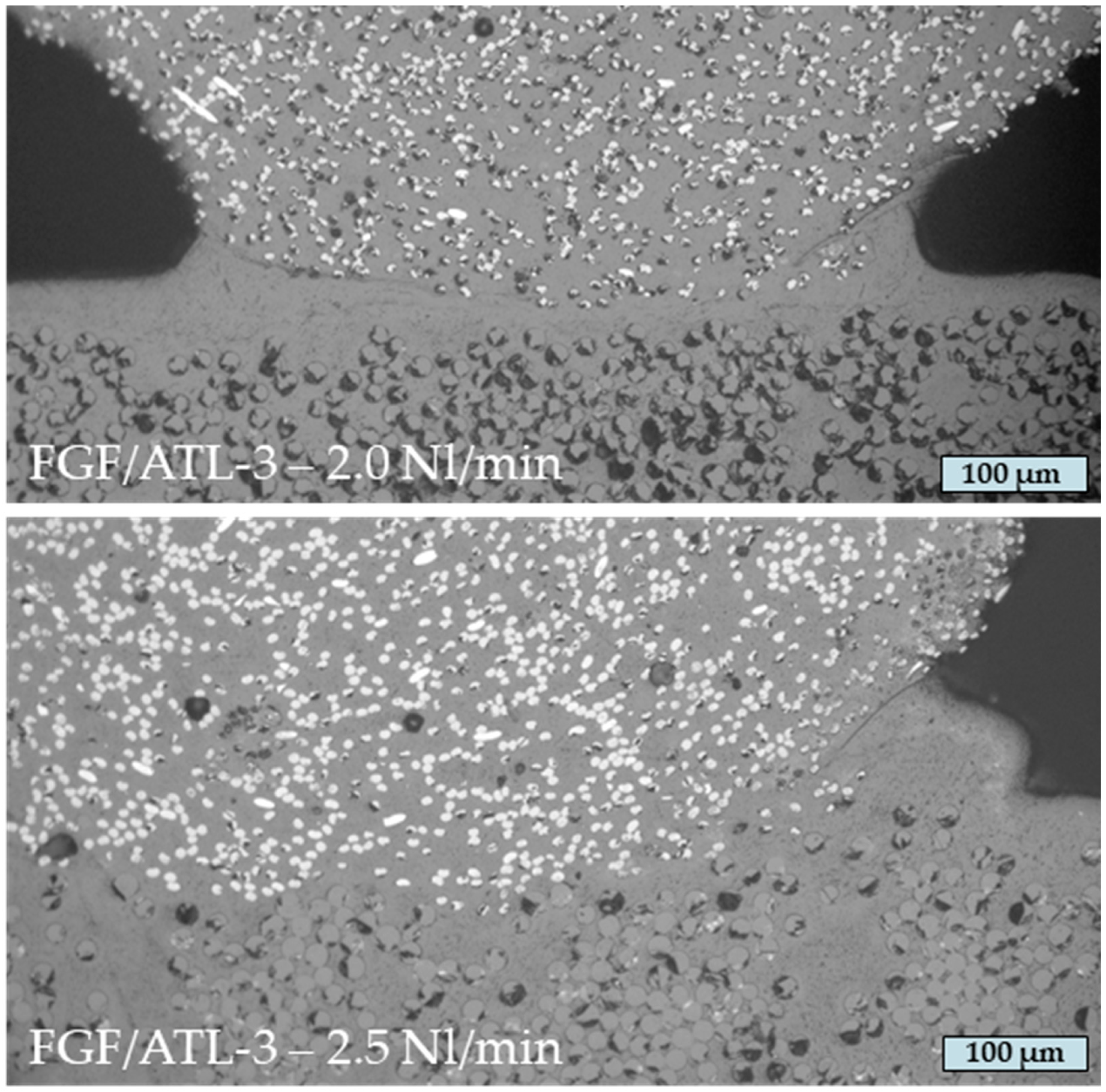
3.2.1. Morphological Analysis

Micrographs of the interface of the hybrid test samples manufactured by fused granular fabrication and additional automated tape laying are shown in Figure 16. As can be seen, there are significant differences in the interface quality between the samples, depending on the surface roughness of the FGF plates. If the shape of the FGF layer lines is unaltered and the matrix material of the UD tapes fails to fill the gaps, the UD tape will not attain full contact with the entire FGF surface. This is because of the limited flexibility of the UD tapes and the fixed diameter of the consolidation roll. As also can be seen in Figure 16, with the height variation in the different FGF layer lines some are not in contact with the UD tape at all. A possible reason could be that the gas volume used during the ATL process was too low, or the layup speed was too high to completely melt the FGF surface. In consequence, the matrix material of the tape is pushed to the side and sometimes completely fills the gaps between the layers, as can be seen for FGF/ATL-1. However, both good and bad connections between the UD tapes and the FGF material can be found in every sample and the gaps in between are always present. Because of the structural irregularity of FGF-2, the resulting gaps vary the most in size.

3.2.2. Analysis of Process Parameters

The contact area between the UD tape and the printed material increases as the UD tape and the FGF surface melt to a greater depth. Thus, two different gas volume flow rates were tested for the ATL process to analyze the effect on the resulting interface to the FGF structures. An increase in the gas volume flow rate results in higher heat generation and more effective melting of the UD tape and FGF surface, as can be seen in Figure 17 for the test series FGF/ATL-3 with 2.0 and 2.5 Nl/m gas volume flow rates. The FGF material in both micrographs is on the top half and the white dots are carbon fibers directed out of plane. In the bottom half, the UD tape with the glass fibers, which are also directed out of plane, can be seen. The FGF layer lines seem unaltered and push the matrix material of the tapes to the side.
The interface has a significant effect on the resulting mechanical properties in these hybrid fiber-reinforced structures. When the amount of heat absorbed by the UD-tape surface is too low, the diffusion of the matrix polymers in the FGF material is hindered and results in adhesion that is too weak to strengthen the material significantly. This can be seen in the stress/strain diagrams in Figure 18 that show the bending tests for the two analyzed gas volume flow rates of FGF/ATL-3. The drops in stress of the samples manufactured with 2.0 Nl/m gas volume flow rate are exactly where the UD tapes became detached from the FGF material without breaking. The increase of 0.5 Nl/m in the gas volume flow rate resulted in doubling the maximum stress. During hybrid additive manufacturing with ATL and gas-assisted heating, it is therefore essential to find an optimum gas volume flow rate at a given process speed for each UD tape and FGF material combination. The amount of thermal energy that is introduced into the interface in the tape-laying process has been shown to be the most critical parameter on the mechanical properties and tape adhesion [43,44]. When the adhesion between the UD tape and the printed material is sufficiently robust, our observations suggest that the UD tape will experience failure through tearing rather than detachment from the substrate.

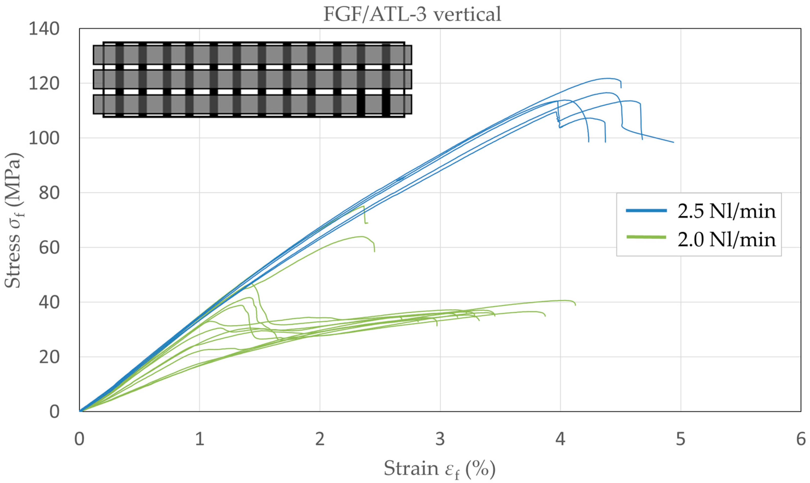
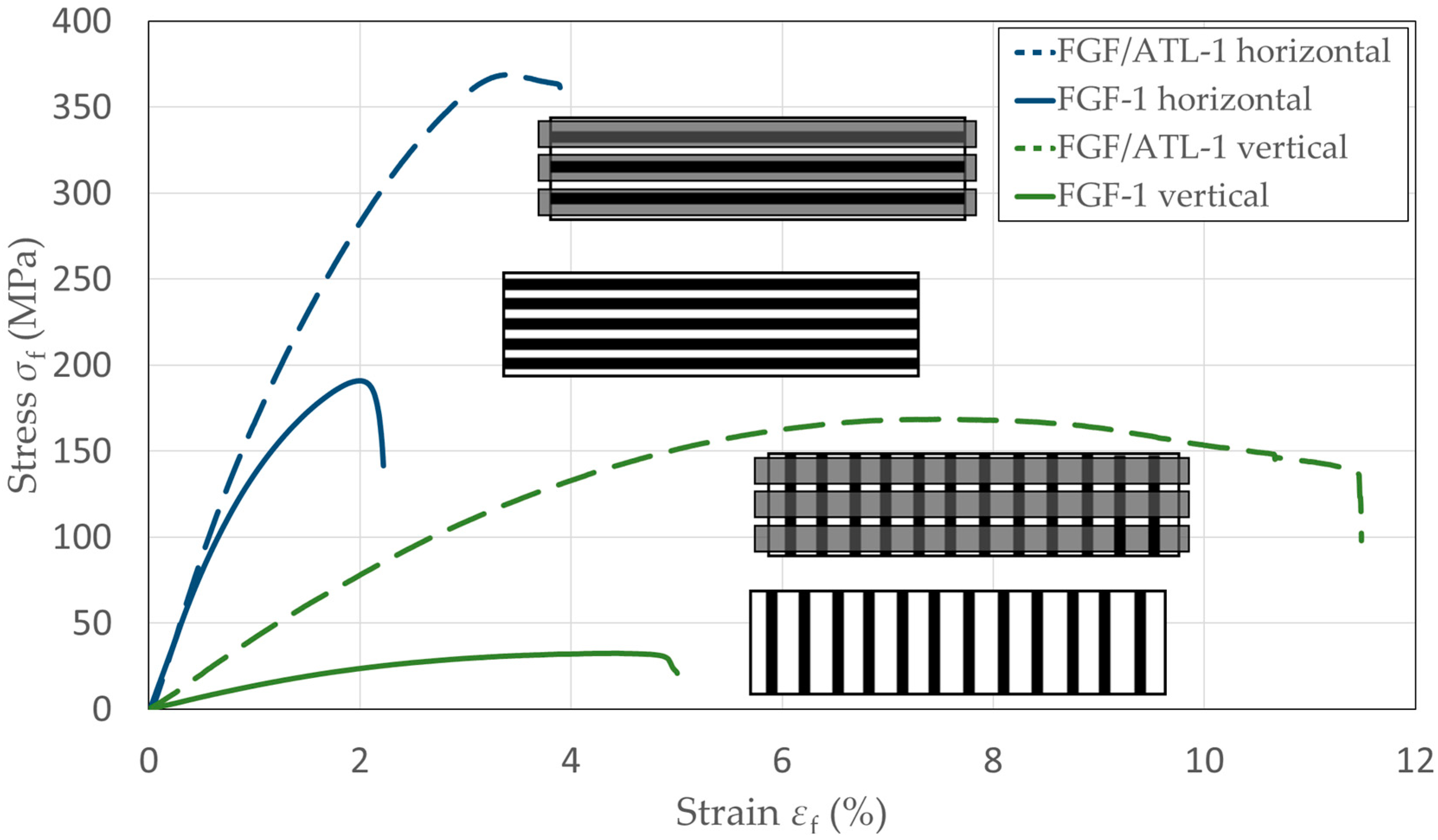
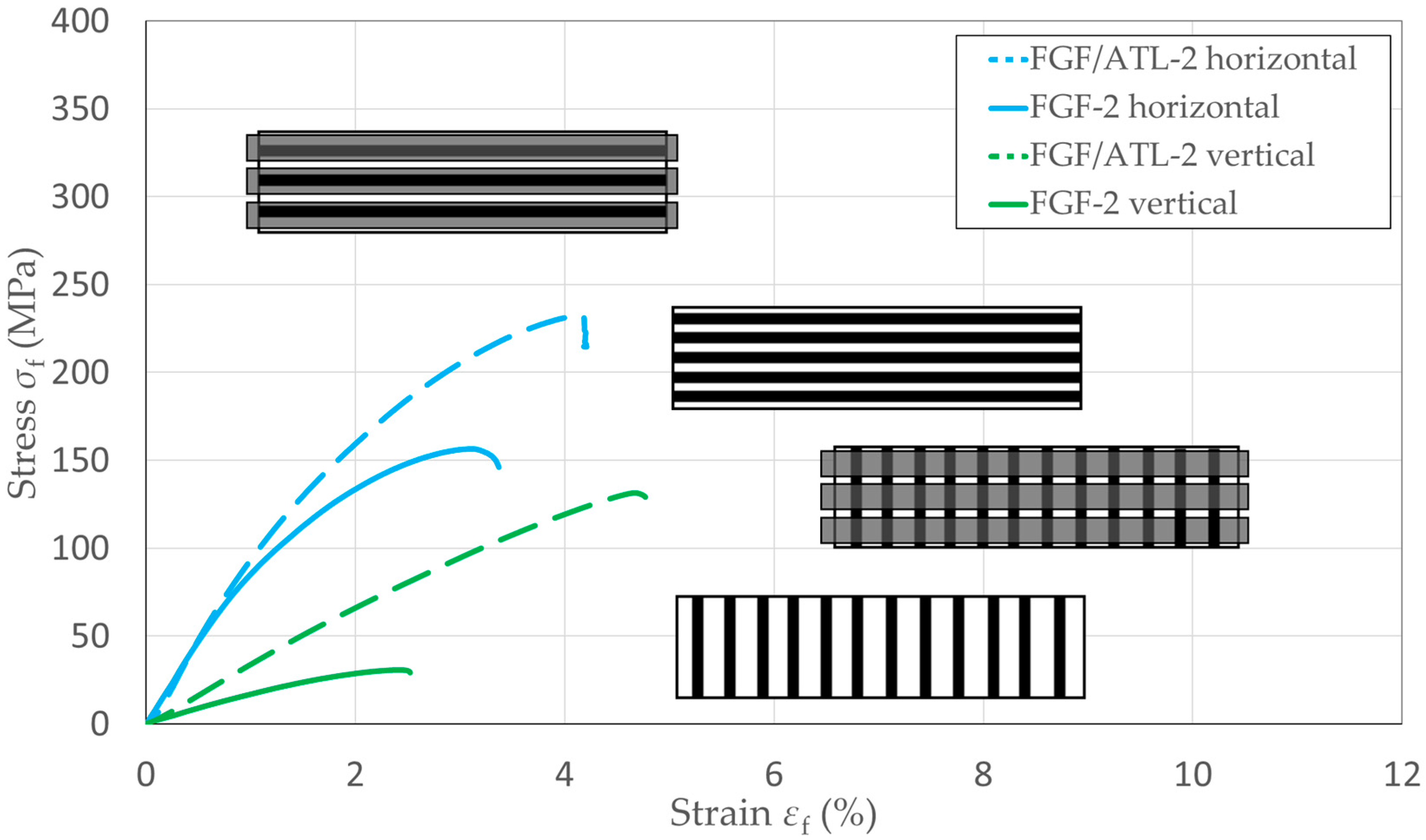
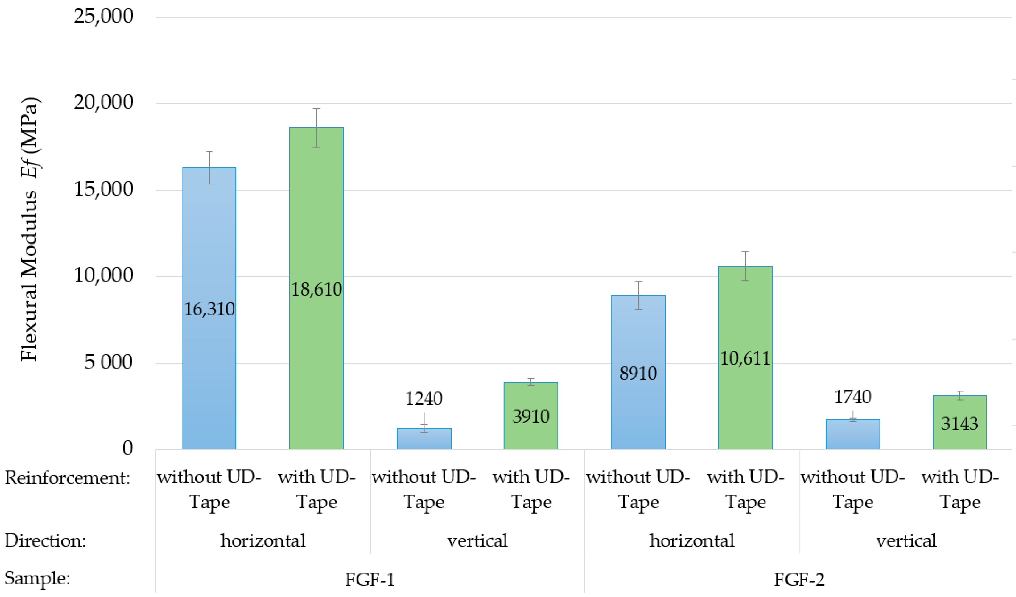
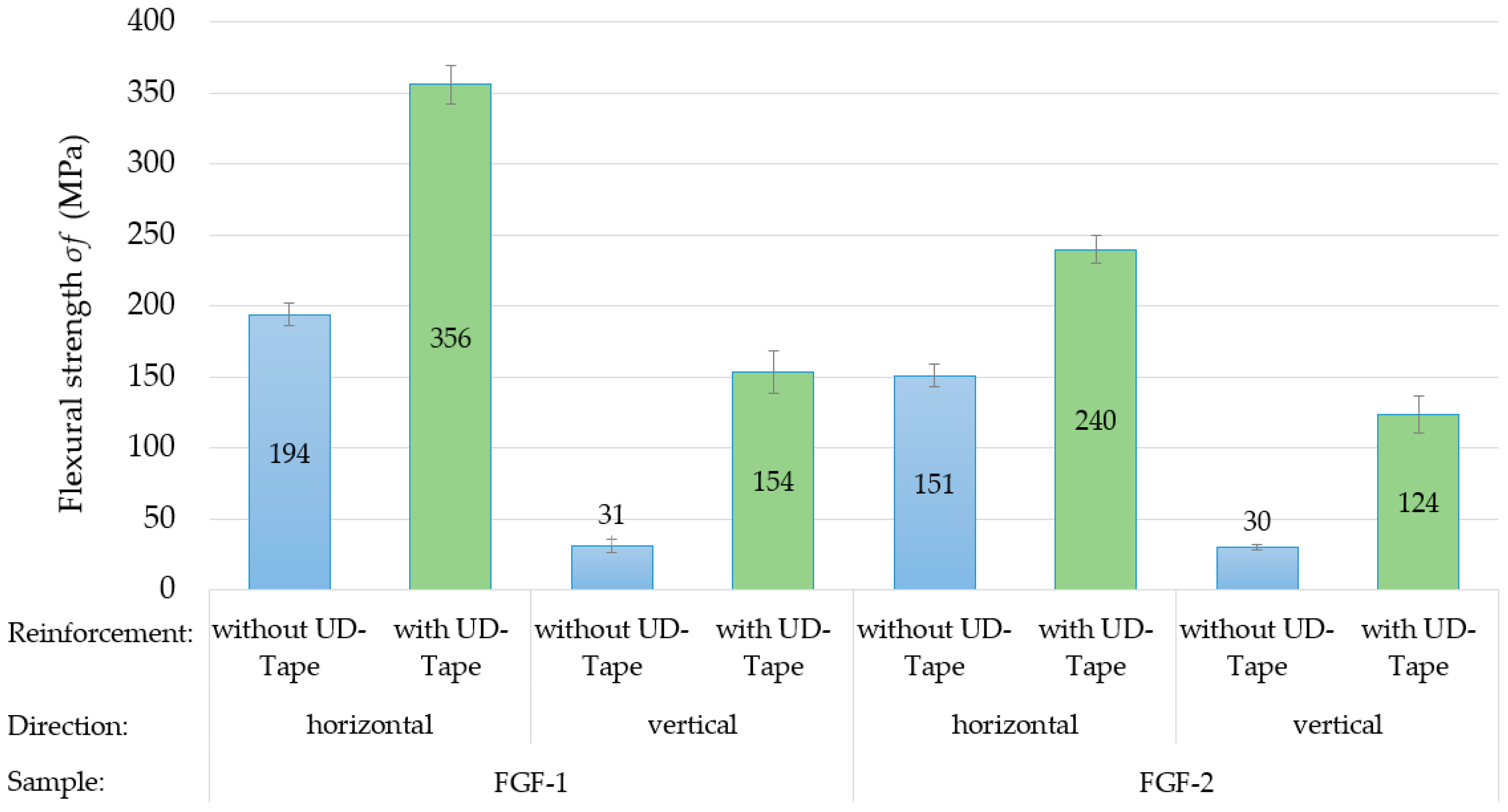
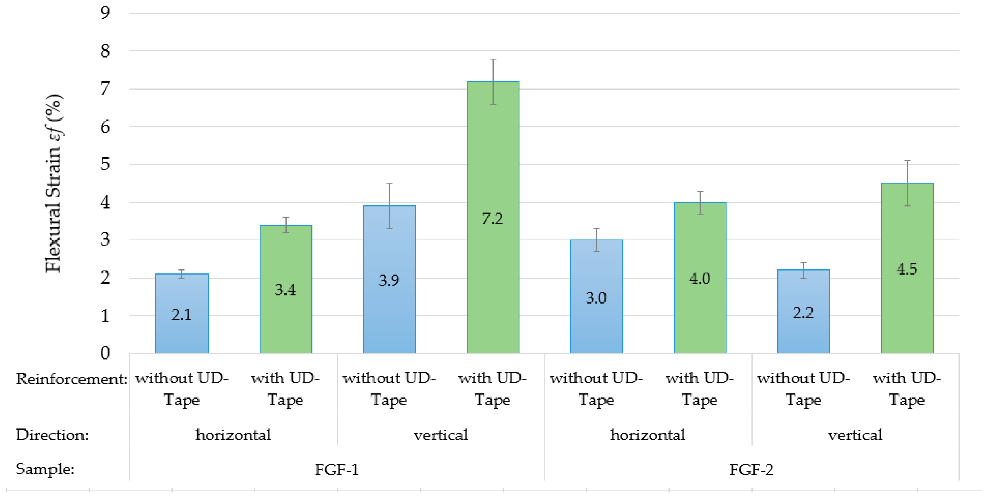
3.2.3. Mechanical Analysis

Figure 19 and Figure 20 show the stress/strain curves from the bending tests of hybrid FGF and ATL test samples in both layer configurations, with and without UD-tape reinforcement of FGF-1 and FGF-2. The UD tapes were located on the bottom side of the samples during the test and therefore experienced a tension load. For both plate types and in both testing directions, a significant increase in mechanical properties was found.
The resulting mechanical properties from the bending test of FGF/ATL-1 and FGF/ATL-2 are shown in the Figure 21, Figure 22 and Figure 23. There is a significant increase in flexural modulus, flexural strength, and strain at break when the UD tapes are added in the hybrid samples. For FGF/ATL-1, the flexural strength increased by a factor of five in the vertical testing direction and is close to the horizontal value without tape. The low flexural modulus of FGF/ATL-2 can be contributed to the fiber misalignment in FGF-2, as discussed previously. For both FGF/ATL-1 and FGF/ATL-2, the increase in mechanical properties by the UD tapes is higher for the vertical testing direction. FGF-1, possessing the smallest layer height and therefore the lowest surface roughness, is expected to have the largest contact area with the tape. FGF/ATL-1 also has the highest UD tape to FGF plate thickness ratio. Because the UD tape has a much higher tensile strength than the printed FGF material, an increase in flexural strength is expected with the increase in tape to plate thickness ratio when the tape is on the bottom side and experiences a tension load during the bending test. However, if the tape is on the top side of the specimen during the bending test or is perpendicular to the testing direction, then it does not increase the mechanical properties in that significant range.

4. Conclusions

Three different plates of carbon fiber-reinforced polyamide 6 were fabricated by fused granular fabrication (FGF) and characterized by morphological and mechanical analysis. The following conclusions were found:
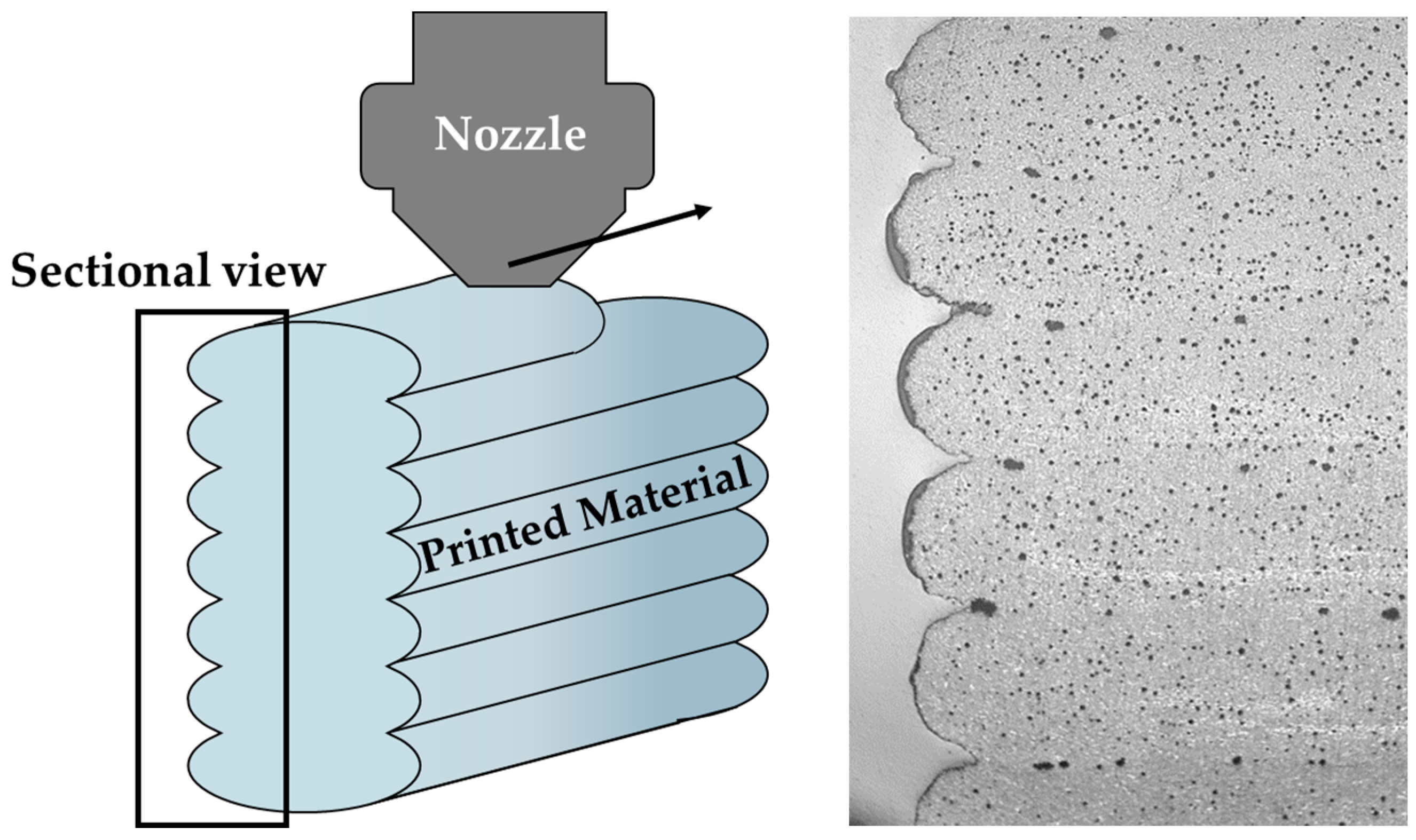
The process parameters have a strong influence on the surface roughness and mechanical properties. Especially the extrusion width, the layer height, and nozzle diameter ratios were found to be the essential factors affecting the regularity of printed geometry, surface quality, and misalignment of the reinforcing fibers in the FGF layers. This fact has a significant impact on the mechanical properties, particularly in the horizontal test direction, as found in the tensile tests of the FGF test samples.
By respecting optimal printing process parameters, comparable values for the elastic modulus and tensile strength of the manufactured FGF materials to the datasheet values from injection-molded samples could be achieved.
Additional automated tape laying (ATL) can significantly increase the mechanical properties of FGF structures, in some cases by several times. This was demonstrated by tape-laying glass-fiber-reinforced polyamide 6 UD tapes on the FGF plates.
For ATL using gas as the heat source, it is essential to find the optimum gas volume flow rate at a given speed and UD tape and FGF material combination. An amount of heat absorbed by UD tape that is too low does not ensure sufficient diffusion of the matrix polymers into the FGF structure. As a result, it does not lead to effective reinforcement of the FGF material as the adhesion to the UD tapes is too weak.
Lower surface roughness of the FGF materials leads to fewer gaps in the UD tape and therefore better stress transfer and higher mechanical values of resulting flexural modulus and strength, as demonstrated by the bending tests. Further improvement and analysis of the adhesion between the FGF materials and UD tapes are needed to determine optimal process parameters for both processes. Additionally, for multilayer components the tape–tape interface needs to be investigated.

Author Contributions

Conceptualization, P.H.; data curation, B.B., O.K. and M.S.; formal analysis, S.S. (Simon Scholz), B.B. and M.S.; funding acquisition, M.Z., R.S. and S.S. (Sebastian Scholz); investigation, B.B. and M.V.; methodology, P.H.; project administration, P.H. and S.S. (Sebastian Scholz); supervision, P.H.; validation, M.V.; writing—original draft, P.H., S.S. (Simon Scholz) and O.K.; writing—review and editing, P.H., R.S., M.S. and O.K. All authors have read and agreed to the published version of the manuscript.

Funding

This research received no external funding.

Data Availability Statement

Data is contained within the article.

Conflicts of Interest

The authors declare no conflicts of interest.

References

  1. Kristiawan, R.B.; Imaduddin, F.; Ariawan, D.; Ubaidillah, U.; Arifin, Z. A review on the fused deposition modeling (FDM) 3D printing: Filament processing, materials, and printing parameters. Open Eng. 2021, 11, 639–649. [Google Scholar] [CrossRef]
  2. Love, L.J.; Duty, C.E.; Post, B.K.; Lind, R.F.; Lloyd, P.D.; Kunc, V.; Peter, W.H.; Blue, C.A. Breaking Barriers in Polymer Additive Manufacturing. In Proceedings of the SAMPE Conference, Baltimore, MD, USA, 19–20 May 2015. [Google Scholar]
  3. Doshi, M.; Mahale, A.; Singh, S.K.; Deshmukh, S. Printing parameters and materials affecting mechanical properties of FDM-3D printed Parts: Perspective and prospects. Mater. Today Proc. 2022, 50, 2269–2275. [Google Scholar] [CrossRef]
  4. Ahuja, B.; Karg, M.; Schmidt, M. Additive manufacturing in production: Challenges and opportunities. In Proceedings of the SPIE LASE: Laser 3D Manufacturing II, San Francisco, CA, USA, 7–12 February 2015. [Google Scholar]
  5. Huang, Y.; Leu, M.C.; Mazumder, J.; Donmez, A. Additive Manufacturing: Current State, Future Potential, Gaps and Needs, and Recommendations. J. Manuf. Sci. Eng. 2015, 137, 014001. [Google Scholar] [CrossRef]
  6. Fleury, A.; Gregory, M.; Bennett, D. The future of manufacturing. J. Manuf. Technol. Manag. 2007, 18, 323–325. [Google Scholar] [CrossRef]
  7. Pignatelli, F.; Percoco, G. An application- and market-oriented review on large format additive manufacturing, focusing on polymer pellet-based 3D printing. Prog. Addit. Manuf. 2022, 7, 1363–1377. [Google Scholar] [CrossRef]
  8. Post, B.K.; Lind, R.F.; Lloyd, P.D.; Kunc, V.; Linhal, J.M.; Love, L.J. The economics of big area additive manufacturing. In Proceedings of the 27th Annual International Solid Freeform Fabrication Symposium—An Additive Manufacturing Conference, Austin, TX, USA, 8–10 August 2016. [Google Scholar]
  9. Duty, C.E.; Kunc, V.; Compton, B.; Post, B.; Erdman, D.; Smith, R.; Lind, R.; Lloyd, P.; Love, L. Structure and mechanical behavior of Big Area Additive Manufacturing (BAAM) materials. Rapid Prototyp. J. 2017, 23, 181–189. [Google Scholar] [CrossRef]
  10. Silva, R.; Sereno, P.; Mateus, A.; Mitchell, G.R.; Carreira, P.; Santos, C.; Vitorino, J.; Domingues, J. Adaptive Platforms and Flexible Deposition System for Big Area Additive Manufacturing (BAAM). Appl. Mech. Mater. 2019, 890, 3–20. [Google Scholar] [CrossRef]
  11. Sam-Daliri, O.; Ghabezi, P.; Flanagan, T.; Finnegan, W.; Mitchell, S.; Harrison, N. Recovery of Particle Reinforced Composite 3D Printing Filament from Recycled Industrial Polypropylene and Glass Fibre Waste. In Proceedings of the 8th World Congress on Mechanical, Chemical, and Material Engineering MCM’22, Prague, Czech Republic, 31 July–2 August 2022. [Google Scholar]
  12. Sam-Daliri, O.; Ghabezi, P.; Steinbach, J.; Flanagan, T.; Finnegan, W.; Mitchell, S.; Harrison, N. Experimental study on mechanical properties of material extrusion additive manufactured parts from recycled glass fibre-reinforced polypropylene composite. Compos. Sci. Technol. 2023, 241, 110125. [Google Scholar] [CrossRef]
  13. Mohamed, O.A.; Masood, S.H.; Bhowmik, J.L. Optimization of fused deposition modeling process parameters: A review of current research and future prospects. Adv. Manuf. 2015, 3, 42–53. [Google Scholar] [CrossRef]
  14. Ajinjeru, C.; Kishore, V.; Lindahl, J.; Sudbury, Z.; Hassen, A.A.; Post, B.; Love, L.; Kunc, V.; Duty, C. The influence of dynamic rheological properties on carbon fiber-reinforced polyetherimide for large-scale extrusion-based additive manufacturing. Int. J. Adv. Manuf. Technol. 2018, 99, 411–418. [Google Scholar] [CrossRef]
  15. Ajinjeru, C.; Kishore, V.; Chen, X.; Hershey, C.; Lindhal, J.; Kunc, V.; Hassen, A.A.; Duty, C. Rheological survey of carbon fiber-reinforced high-temperature thermoplastics for big area additive manufacturing tooling applications. J. Thermoplast. Compos. Mater. 2021, 34, 1443–1461. [Google Scholar] [CrossRef]
  16. Billah, K.M.M.; Lorenzana, F.A.R.; Martinez, N.L.; Wicker, R.B.; Espalin, D. Thermomechanical characterization of short carbon fiber and short glass fiber-reinforced ABS used in large format additive manufacturing. Addit. Manuf. 2020, 35, 101299. [Google Scholar] [CrossRef]
  17. Ngo, T.D.; Kashani, A.; Imbalzano, G.; Nguyen, K.T.Q.; Hui, D. Additive manufacturing (3D printing): A review of materials, methods, applications and challenges. Compos. B Eng. 2018, 143, 172–196. [Google Scholar] [CrossRef]
  18. Zohdi, N.; Yang, R. Material Anisotropy in Additively Manufactured Polymers and Polymer Composites: A Review. Polymers 2021, 13, 3368. [Google Scholar] [CrossRef]
  19. Haque, A.N.M.A.; Naebe, M. Tensile Properties of Natural Fibre-Reinforced FDM Filaments: A Short Review. Sustainability 2023, 15, 16580. [Google Scholar] [CrossRef]
  20. Liu, X.; Chi, B.; Jiao, Z.; Tan, J.; Liu, F.; Yang, W. A large-scale double-stage-screw 3D printer for fused deposition of plastic pellets. J. Appl. Polym. Sci. 2017, 134, 45147. [Google Scholar] [CrossRef]
  21. Chesser, P.; Post, B.; Roschli, A.; Carnal, C.; Lind, R.; Borish, M.; Love, L. Extrusion control for high quality printing on Big Area Additive Manufacturing (BAAM) systems. Addit. Manuf. 2019, 28, 445–455. [Google Scholar] [CrossRef]
  22. Wickramasinghe, S.; Do, T.; Tran, P. FDM-Based 3D Printing of Polymer and Associated Composite: A Review on Mechanical Properties, Defects and Treatments. Polymers 2020, 12, 1529. [Google Scholar] [CrossRef]
  23. Raspall, F.; Velu, R.; Vaheed, N.M. Fabrication of complex 3D composites by fusing automated fiber placement (AFP) and additive manufacturing (AM) technologies. Adv. Manuf. Polym. Compos. Sci. 2019, 5, 6–16. [Google Scholar] [CrossRef]
  24. Yassin, K.; Hojjati, M. Processing of thermoplastic matrix composites through automated fiber placement and tape laying methods: A review. J. Thermoplast. Compos. 2018, 31, 1676–1725. [Google Scholar] [CrossRef]
  25. Voelkl, H.; Kießkalt, A.; Wartzack, S. Design for Composites: Derivation of Manufacturable Geometries for Unidirectional Tape Laying. Proc. Des. Soc. Int. Conf. Eng. Des. 2019, 1, 2687–2696. [Google Scholar] [CrossRef]
  26. Kropka, M.; Muehlbacher, M.; Neumeyer, T.; Altstaedt, V. From UD-tape to Final Part—A Comprehensive Approach towards Thermoplastic Composites. Procedia CIRP 2017, 66, 96–100. [Google Scholar] [CrossRef]
  27. Brasington, A.; Sacco, C.; Halbritter, J.; Wehbe, R.; Harik, R. Automated fiber placement: A review of history, current technologies, and future paths forward. Compos. Part C 2021, 6, 100182. [Google Scholar] [CrossRef]
  28. Link, T.; Rosenberg, P.; Henning, F. Prediction of Gaps in Automated Tape Laying and Their Influence on Porosity in Consolidated Laminates. J. Compos. Sci. 2022, 6, 207. [Google Scholar] [CrossRef]
  29. Jayasekara, D.; Lai, N.Y.G.; Wong, K.-H.; Pawar, K.; Zhu, Y. Level of automation (LOA) in aerospace composite manufacturing: Present status and future directions towards industry 4.0. J. Manuf. Syst. 2022, 62, 44–61. [Google Scholar] [CrossRef]
  30. Zhang, L.; Wang, X.; Pei, J.; Zhou, Y. Review of automated fibre placement and its prospects for advanced composites. J. Mater. Sci. 2020, 55, 7121–7155. [Google Scholar] [CrossRef]
  31. Dhinakaran, V.; Surendar, K.V.; Hasunfur Riyaz, M.S.; Ravichandran, M. Review on study of thermosetting and thermoplastic materials in the automated fiber placement process. Mater. Today Proc. 2020, 27, 812–815. [Google Scholar] [CrossRef]
  32. F3-Compositor Enables 3D Deposition and Simultaneous Joining of Thermoplastic UD Tape Semi-Finished Products. Available online: https://www.imws.fraunhofer.de/en/presse/pressemitteilungen/f3--compositor-enables-3d-deposition-and-simultaneous-joining-of.html (accessed on 9 November 2023).
  33. DIN EN ISO 178:2019-08; Plastics—Determination of Flexural Properties (ISO 178:2019). German version EN ISO 178:2019; ISO: Geneva, Switzerland, 2019.
  34. DIN EN ISO 1110:2019-09; Plastics—Polyamides—Accelerated Conditioning of Test Specimens (ISO 1110:2019). German version EN ISO 1110:2019; ISO: Geneva, Switzerland, 2019.
  35. DIN EN ISO 527-1:2019-12; Lastics—Determination of Tensile Properties—Part 1: General Principles (ISO 527-1:2019). German version EN ISO 527-1:2019; ISO: Geneva, Switzerland, 2019.
  36. Ahn, D.; Kweon, J.-H.; Kwon, S.; Song, J.; Lee, S. Representation of surface roughness in fused deposition modelling. J. Mater. Process. Technol. 2009, 209, 5593–5600. [Google Scholar] [CrossRef]
  37. Maier, R.; Bucaciuc, S.-G.; Mandoc, A.C. Reducing Surface Roughness of 3D Printed Short-Carbon Fiber Reinforced Composites. Materials 2022, 15, 7398. [Google Scholar] [CrossRef]
  38. Consul, P.; Beuerlein, K.; Luzha, G.; Drechsler, K. Effect of Extrusion Parameters on Short Fiber Alignment in Fused Filament Fabrication. Polymers 2021, 13, 2443. [Google Scholar] [CrossRef]
  39. Tagscherer, N.; Bär, A.; Zaremba, S.; Drechsler, K. Mechanical Analysis of Parameter Variations in Large-Scale Extrusion Additive Manufacturing of Thermoplastic Composites. J. Manuf. Process. 2022, 6, 36. [Google Scholar] [CrossRef]
  40. Barera, G.; Dul, S.; Pegoretti, A. Screw Extrusion Additive Manufacturing of Carbon Fiber Reinforced PA6 Tools. J. Mater. Eng. Perform. 2023, 32, 9579–9597. [Google Scholar] [CrossRef]
  41. König, M.; Diekmann, J.; Lahres, M.; Middendorf, P. Experimental investigation of process-structure effects on interfacial bonding strength of a short carbon fiber/polyamide composite fabricated by fused filament fabrication. Prog. Addit. Manuf. 2022, 7, 593–607. [Google Scholar] [CrossRef]
  42. Kepenekci, M.; Gharehpapagh, B.; Yaman, U.; Özerinc, S. Mechanical performance of carbon fiber-reinforced polymer cellular structures manufactured via fused filament fabrication. Polym. Compos. 2023, 44, 4654–4668. [Google Scholar] [CrossRef]
  43. Atzler, F.; Raps, L.; Freund, J.; Tröger, S.; Hümbert, S. Bonding of Low-Melting Polyaryletherketone onto Polyamide 6: A Concept for Molds for Automated Fiber Placement. J. Compos. Sci. 2023, 7, 371. [Google Scholar] [CrossRef]
  44. Janssen, H.; Peters, T.; Brecher, C. Efficient Production of Tailored Structural Thermoplastic Composite Parts by Combining Tape Placement and 3d Printing. Procedia CIRP 2017, 66, 91–95. [Google Scholar] [CrossRef]
Figure 1. Fused granular fabrication unit used to produce fiber-reinforced polyamide test structures.
Jmmp 08 00025 g001
Figure 2. Schematic illustration of the fused granular fabrication printing path direction (left, top view) and the resulting “ribbed ridge” test structure (right).
Jmmp 08 00025 g002
Figure 3. Demonstration of the test sample preparation from the fused granular fabrication structures in horizontal (printing) and vertical direction.
Jmmp 08 00025 g003
Figure 4. Dimensions of the fused granular fabrication tensile (left) and bending test specimen (right).
Jmmp 08 00025 g004
Figure 5. Automated tape-laying unit used to produce fiber-reinforced polyamide test structures (a), close-up of the tape-laying head (b), and schematic illustration of the tape-laying process (c).
Jmmp 08 00025 g005
Figure 6. Perpendicular (left) and parallel (right) configuration of the UD tapes on the fused granular fabrication printing direction.
Jmmp 08 00025 g006
Figure 7. Schematic illustration of the sectional view (left) and resulting micrograph (right) of the fused granular fabrication test samples.
Jmmp 08 00025 g007
Figure 8. Experimental setup of the three-point bending test (left) and the tensile test (right) for the test specimen from fused granular fabrication and automated tape laying.
Jmmp 08 00025 g008
Figure 9. Micrographs showing the surface of the fused granular fabrication test samples.
Jmmp 08 00025 g009
Figure 10. Fracture behavior of the fused granular fabrication tensile samples in vertical (a) and horizontal (b) direction and bending samples in vertical (c) and horizontal (d) direction.
Jmmp 08 00025 g010
Figure 11. Stress/strain curves for the fused granular fabrication tensile test samples with horizontal and vertical layer configuration.
Jmmp 08 00025 g011
Figure 12. Micrographs of the fused granular fabrication test samples showing areas with a high density of carbon fibers that are not aligned with the print direction. Misaligned fibers appear as thin white streaks.
Jmmp 08 00025 g012
Figure 13. Elastic modulus of the fused granular fabrication test samples (green columns) in comparison to the datasheet value for injection-molded test samples (blue column).
Jmmp 08 00025 g013
Figure 14. Tensile strength of the fused granular fabrication test samples (green columns) in comparison to the datasheet value for injection-molded test samples (blue column).
Jmmp 08 00025 g014
Figure 15. Strain at break of the fused granular fabrication test samples (green columns) in comparison to the datasheet value for injection-molded test samples (blue column).
Jmmp 08 00025 g015
Figure 16. Micrographs showing the interface of the hybrid fused granular fabrication and automated tape-laying test samples.
Jmmp 08 00025 g016
Figure 17. Micrographs showing the interface of hybrid fused granular fabrication and automated tape-laying test samples with different gas volume flow rates during the tape-laying process.
Jmmp 08 00025 g017
Figure 18. Stress/strain curves from bending tests of hybrid fused granular fabrication (FGF-3) and automated tape-laying test samples with different gas volume flow rates during the tape-laying process.
Jmmp 08 00025 g018
Figure 19. Stress/strain curves from bending tests of hybrid fused granular fabrication (FGF-1) and automated tape-laying test samples in horizontal and vertical layer configuration with and without UD-tape reinforcement.
Jmmp 08 00025 g019
Figure 20. Stress/strain curves from bending tests of hybrid fused granular fabrication (FGF-2) and automated tape-laying test samples in horizontal and vertical layer configuration with and without UD-tape reinforcement.
Jmmp 08 00025 g020
Figure 21. Comparison of flexural modulus of hybrid fused granular fabrication and automated tape-laying test samples (green columns) with fused granular fabrication test samples without UD tapes (blue columns).
Jmmp 08 00025 g021
Figure 22. Comparison of flexural strength of hybrid fused granular fabrication and automated tape-laying test samples (green columns) with fused granular fabrication test samples without UD tapes (blue columns).
Jmmp 08 00025 g022
Figure 23. Comparison of strain at break for hybrid fused granular fabrication and automated tape-laying test samples (green columns) with fused granular fabrication test samples without UD tapes (blue columns).
Jmmp 08 00025 g023
Table 1. Properties of the used fiber-reinforced polyamide composite materials.
Composite MaterialPA6/CF40PA6/GF60-UD
GradeAKROMID® B3 ICF 40 blackCelstran® CFR-TP PA6-GF60
SupplierAKRO-PLASTIC GmbHTICONA GmbH
Reinforcementcarbon fiberglass fiber
Fiber Weight Content (%)4060
Density (g/cm3)1.311.69
Tensile Modulus (GPa)32 (dry)
13.6 (conditioned)
29.7 (dry)
27.5 (conditioned)
Tensile Strength (MPa)220 (dry)
135 (conditioned)
679 (dry)
642 (conditioned)
Melting Temperature (°C)220220
Table 2. Processing parameters and resulting wall thicknesses of the fused granular fabrication process.
Plate TypePrinting Speed
v
(mm/s)
Layer Height
h
(mm)
Nozzle Diameter
d
(mm)
Extrusion Width
w
(mm)
Ratio
w/d
(-)
Ratio
h/d
(-)
FGF-14000.501.52.71.800.33
FGF-22000.751.54.32.870.5
FGF-31251.003.05.21.730.33
Table 3. Processing parameters of the automated tape-laying process.
Laying Speed v
(mm/s)
Force on Tape
F
(N)
Gas Flow Rate
V
(Nl/min)
Gas Composition
2 H2 + O2
(%)
Roll Temperature
T
(°C)
250602.0/2.510020
Table 4. Surface roughness and density of the fused granular fabrication test samples.
SampleSurface Roughness
Ra
(µm)
Surface Roughness
Rz
(µm)
Density
ρ
(g/cm3)
FGF-1635331.301
FGF-29514751.273
FGF-3957031.277
Disclaimer/Publisher’s Note: The statements, opinions and data contained in all publications are solely those of the individual author(s) and contributor(s) and not of MDPI and/or the editor(s). MDPI and/or the editor(s) disclaim responsibility for any injury to people or property resulting from any ideas, methods, instructions or products referred to in the content.

