Abstract
Cutting tools undergo constant development to meet the demands of higher cutting speeds, difficult-to-cut materials and ecological considerations. One way to improve cutting tools involves transitioning from soldering to adhesive bonding in the manufacturing process. However, there is limited research comparing adhesively bonded tools with soldered tools in woodcutting applications. This paper presents a comparison between adhesively bonded and soldered tools in the cutting of medium-density fiberboards over a cutting distance of 1000 m. The results indicate that adhesively bonded tools are well-suited for machining medium-density fiberboards. Additionally, the cutting-edge radii exhibit a slower increase and the tool temperatures are higher compared to soldered tools. Future research could optimize the damping effect through the precise design of the bonding area. Additionally, investigating a cooling concept for the machining process could help minimize ageing effects.
1. Introduction
In Germany, the woodworking mechanical engineering industry holds significant importance, given its comparable revenue per capita to that of general mechanical engineering. Following the COVID-19 pandemic, the woodworking mechanical engineering industry experienced a revenue growth of 18.4% from 2020 to 2021. Consequently, this industry has undergone more substantial growth compared to the automotive industry (+8.7%), general mechanical engineering (+7.2%), and electronics industry (+14.9%) in this period. It is worth noting that the sector is highly reliant on sales cycles [1]. The considerable challenges involved in wood machining affirm the value of a robust mechanical industry for woodworking.
In solid wood, the alternating growth phases and resulting structure lead to significant anisotropy and inhomogeneity. This natural optimization of the structure provides maximum tensile strength in the longitudinal direction of the tree trunk. Wood-based materials, on the other hand, are structured to mitigate the anisotropy of native wood through fragmentation and recombination, resulting in a more homogeneous material. Wood-based materials facilitate the production of dimensionally stable materials in desired dimensions, utilizing by-products from the wood industry. By employing specific raw material assortments, binders and additives, targeted properties can be achieved in composite materials. Nevertheless, the structure of wood-based materials remains more complex than that of metal. The foremost wood-based materials today include particleboard, medium-density fiberboard (MDF), and plywood. These materials offer versatility and can be tailored to specific applications by adjusting their composition and manufacturing processes [2,3].
Wood machining involves various methods such as milling, sawing, drilling, and turning. The cutting speed for wood machining is typically 5–20 times higher than that for metal machining, placing higher demands on the tool materials [4]. Insufficient cutting speed results in poor surface quality [5]. To achieve optimal surface quality in wood machining, a sharp cutting edge with a cutting edge radius of less than 5 µm, ideally 1 µm, is required [6,7]. Tool life is mostly characterized by the cutting edge radius [8,9]. Pahlitzsch and Sandvoß were among the first to analyze the wear of cutting tools in MDF machining. They found that the main parameters to have an impact on the cutting edge radius are cutting depth, cutting speed, and feed rate. An increase in cutting depth and cutting speed leads to a decrease in tool life, while higher feed rates result in a higher possible cutting distance [10]. Wood machining faces yet another challenge due to high temperatures at the cutting edge, ranging from 400 °C to 800 °C. Wood’s low thermal conductivity results in a significant amount of heat at the tool and workpiece interface. Cooling liquids cannot be utilized as they may affect the wood’s surface quality [9,11]. Additionally, the extractives in wood cause a corrosive environment, which can be detrimental to cutting tools [4,6,7]. Consequently, efficient cutting tools are essential for wood cutting [3].
The standard material for cutting tools in wood machining is tungsten carbide (WC). Carbides, including WC, are commonly used due to their durability [7]. However, the main metallic binder of hard metal tools, cobalt, is deemed a critical raw material by the European Union. The main concern is the great demand in industries such as batteries and the political instability of top mine producers like the Democratic Republic of Congo, which can pose issues in the supply chain [12,13]. Furthermore, the metallic binding phase in WC can react with tannic acids in wood, leading to the leaching out of the cobalt binder and exposing WC grains that may potentially detach. Recently, ceramics have been under study as alternative tool materials for wood machining due to their potential advantages [7,14,15]. Currently, cutting tools are mostly manufactured by soldering hard cutting segments on a tool body, followed by grinding the cutting segments. However, soldering comes with common problems like high temperatures and thus high heat input, which leads to internal stresses within the tool. An alternative, which employs much lower process temperatures, is adhesive bonding [16].
One of the initial developments of adhesively bonded cutting tools dates back to 1989. Darwish et al. conducted a comparative study between a soldered and an adhesively bonded cutting tool by milling EN3B. Even at that early stage, they identified several advantages of the adhesively bonded tool over its soldered counterpart. Their findings indicated that the adhesively bonded tool generated smaller process forces and a reduced wear rate [17].
In 2021, Jachak et al. presented similar results through the milling of EN8. They pointed out, that an adhesively bonded tool has lower cutting forces, a slower wear rate, and produces better surface quality than a soldered tool [18].
Schneider et al. focused their tests on studying damping in cutting tools. They highlighted that tools oscillate upon entering the cutting piece. For better results, minimizing the oscillation is therefore crucial. An efficient way to do this is the transitioning from soldering to adhesive bonding. The damping resulting from the adhesives starts right at the origin of the oscillation. Their experiments and simulations showed that the key parameters influencing damping are Young’s modulus and the thickness of the adhesive layer. They validated their findings through cutting tests with newly designed saw blades for cutting steel. The results indicated that a thicker adhesive layer requires smaller drive torques due to higher damping effects [19].
Uysal et al. compared differently filled adhesives and a clamped tool in the turning of AISI 1040 carbon steel. They showed that all of the adhesives used provided better surface quality and lower cutting forces than the clamped tool. The best results were observed with the neat adhesive without any filler [20].
In addition to a reduction in cutting forces, drive torques, and improved surface quality, there are still several other advantages such as the possibility of reusing tool bodies [16] due to low damage from low bonding temperatures [19] or an increase in performance in cutting speed resulting from the use of new cutting materials [21].
However, there are also some disadvantages to adhesively bonded cutting tools. The most crucial one is the heat accumulation in the tool due to the insulating adhesive [22]. Therefore, Al-Samham investigated the influence of adhesive fillers on tool temperature during cutting. Heat-conductive fillers, like copper powder, were found to be ineffective in reducing heat accumulation. He suggested using cooling to reduce the heat accumulation [23]. Uysal et al. demonstrated that nanographene particles can lower the cutting temperature in comparison to a neat adhesive [20].
All the papers discussed in this work showed promising results for improving cutting tools with adhesive bonding. While the primary focus of these papers is on metal cutting, there are ongoing investigations related to adhesively bonded woodworking tools. Adhesive bonding is a promising technology for woodworking tools due to its potential to design even lighter versions [24]. To achieve an even lighter construction for adhesively bonded tools, Correia et al. conducted a numerical optimization of the bonded joints. They tested different geometries and concluded that an increase in weight due to the enlargement of the insert expands the resulting stresses in the adhesive layer. The most relevant parameter was the angle of the insert so that an adjustment improved the shear behavior [25].
For improvement of the manufacturing process of adhesively bonded wood cutting tools, Gomes et al. investigated the curing process of the adhesive. They compared the possibility of conduction curing of the adhesive with oven curing. They showed that the shear strength of the oven-cured samples is twice as high as the induction-cured ones. The reason for this lies in the rapid heating during induction, resulting in the expansion of gas in the adhesive layer. This expansion cannot dissipate before the complete curing of the adhesive, leading to a reduction of the bonding area and subsequently decreasing the applicable forces. As a possible alternative for achieving faster production times, ultraviolet curing adhesives could be an interesting option [26].
To estimate potential tool life, Sousa et al. also conducted several investigations with different aging methods. All ageing methods yielded different results, the most problematic ones being moisture absorption through water and cooling fluids, coatings for tool base bodies, cleaning tools with sand blasting, and immersion in mineral oils. Nevertheless, they indicated, considering these effects, that it is possible to use an adhesively bonded tool without a significant loss of bond strength due to aging effects. Furthermore, individual cutting wedges can be repaired [27].
Since cooling fluids, as a negative influence on bonding strength, cannot be used in woodworking, they are a promising area for adhesively bonded tools. However, a comparison between an adhesively bonded and soldered tools for woodworking was not found in current research.
The purpose of this paper is to investigate the differences between a soldered and an adhesively bonded wood cutting tool by milling MDF. The study will examine tool wear, process temperatures, and forces. Following the experiments, several conclusions can be drawn:
- Are adhesively bonded tools suitable for cutting MDF?
- Are there noticeable differences in tool wear?
- Are there noticeable differences in the process temperatures and forces?
2. Materials and Methods
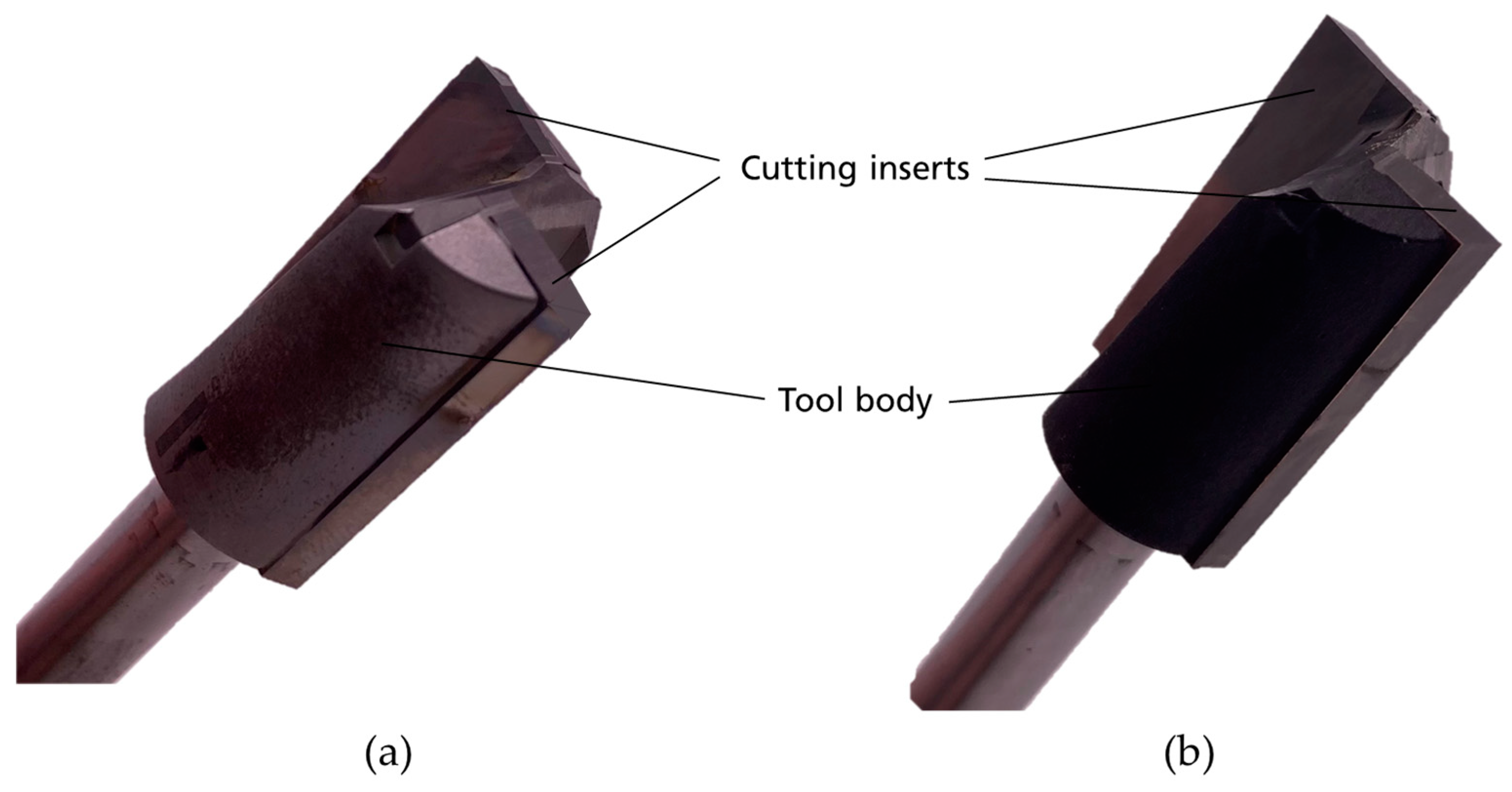
In this paper, two identical router tools (type: 2424-3-5-18097-R) from Jakob Schmid GmbH + Co. KG, Neresheim, Germany are investigated. The tool has a diameter of 18 mm and is equipped with two cutting inserts. The difference between the tools lies in the manufacturing process. One was manufactured by adhesive bonding with a heat-curing epoxy adhesive (Monopox HT2860 from the Company Delo Industrieklebstoffe GmbH & Co. KGaA, Windach, Germany), while the other one underwent a soldering process. The tool body is made of steel, and the cutting inserts are made of tungsten carbide. The tools are seen in Figure 1.

Figure 1.
Adhesively bonded tool (a) and soldered tool (b).
For the work piece, MDF with dimensions of 1000 mm × 500 mm × 18 mm was used. The experiments were performed with a Reichenbacher ECO LT 2012 (Reichenbacher Hamuel GmbH, Dörfles-Esbach, Germany) machining center.
Various tools were used for the extensive measurements in this paper.
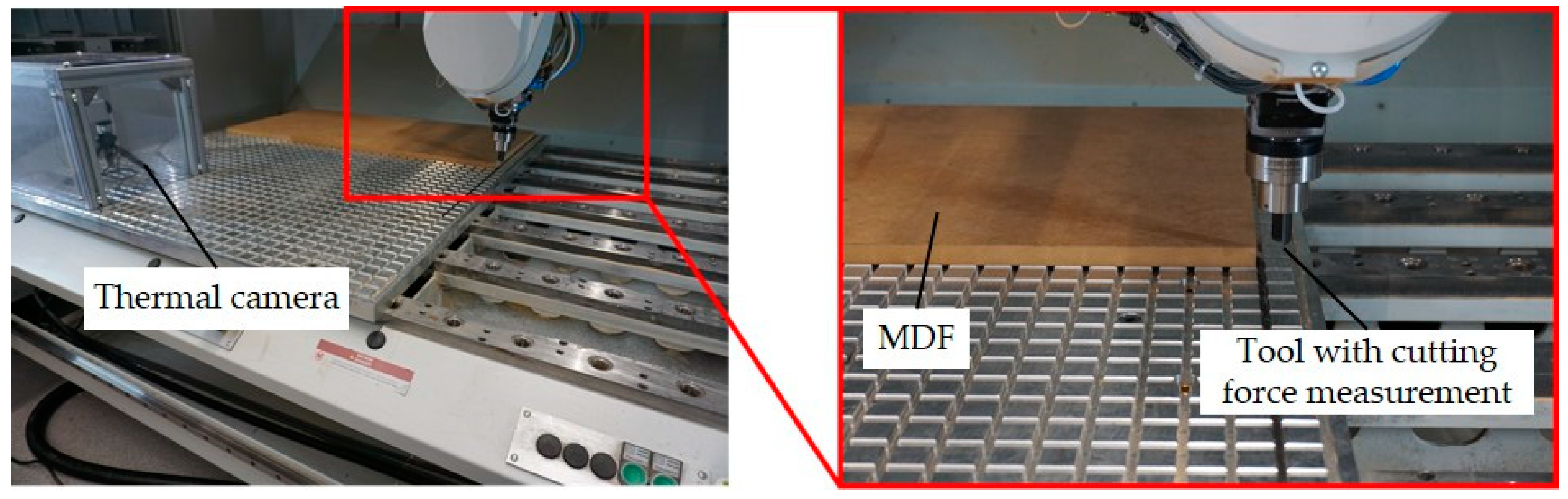
A thermal camera PI400i from Optris GmbH, Berlin, Germany was used for the temperature measurement of the milling tool on a measurement spot, the same for every temperature measurement. A Spike tool holder 1.2 from pro-micron GmbH, Kaufbeuren, Germany recorded cutting forces during the process. The experimental setup can be seen in Figure 2.
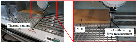
Figure 2.
Experimental set up within the Reichenbacher machining center.
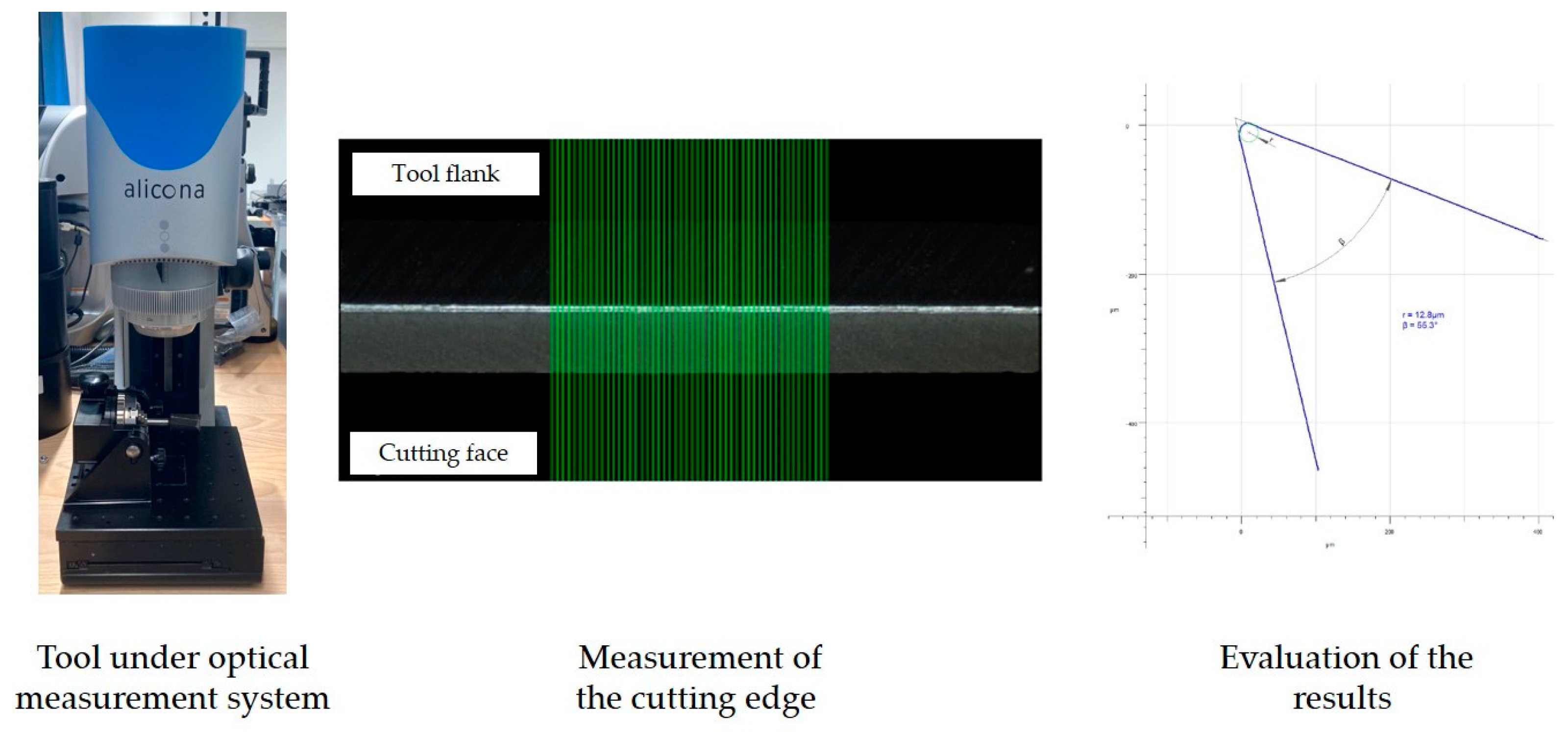
An Alicona Infinite Focus SL from Alicona Imaging GmbH, Raaba, Austria measured the cutting edge radius via an optical method. The procedure is shown in Figure 3. Wear was documented with a VHX7000 from Keyence Deutschland GmbH, Neu-Isenburg, Germany.

Figure 3.
Measurement method of the Alicona Infinite Focus SL.
Two different milling approaches were applied in the experiments: Initially, ten notches were milled in the medium-density fiberboards. Subsequently, rebate cutting of the notched fiberboards was employed to generate tool wear. The entire procedure was repeated three times, resulting in notches being milled after 0 m, 500 m and 1000 m cutting length. A new work piece was used for each new cycle, and the tools were allowed to cool down to room temperature for every new set of notches. Due to the periodic entry and exit from the work piece, the mechanical load on the cutting edge increased. The axial cutting depth for all tests was 10 mm. Cutting experiments were carried out for both adhesively bonded and soldered tools. In this paper, one adhesively bonded tool and one soldered tool were investigated. The machining parameters used for both approaches are summarized in Table 1.

Table 1.
Cutting parameters used for the milling approaches.
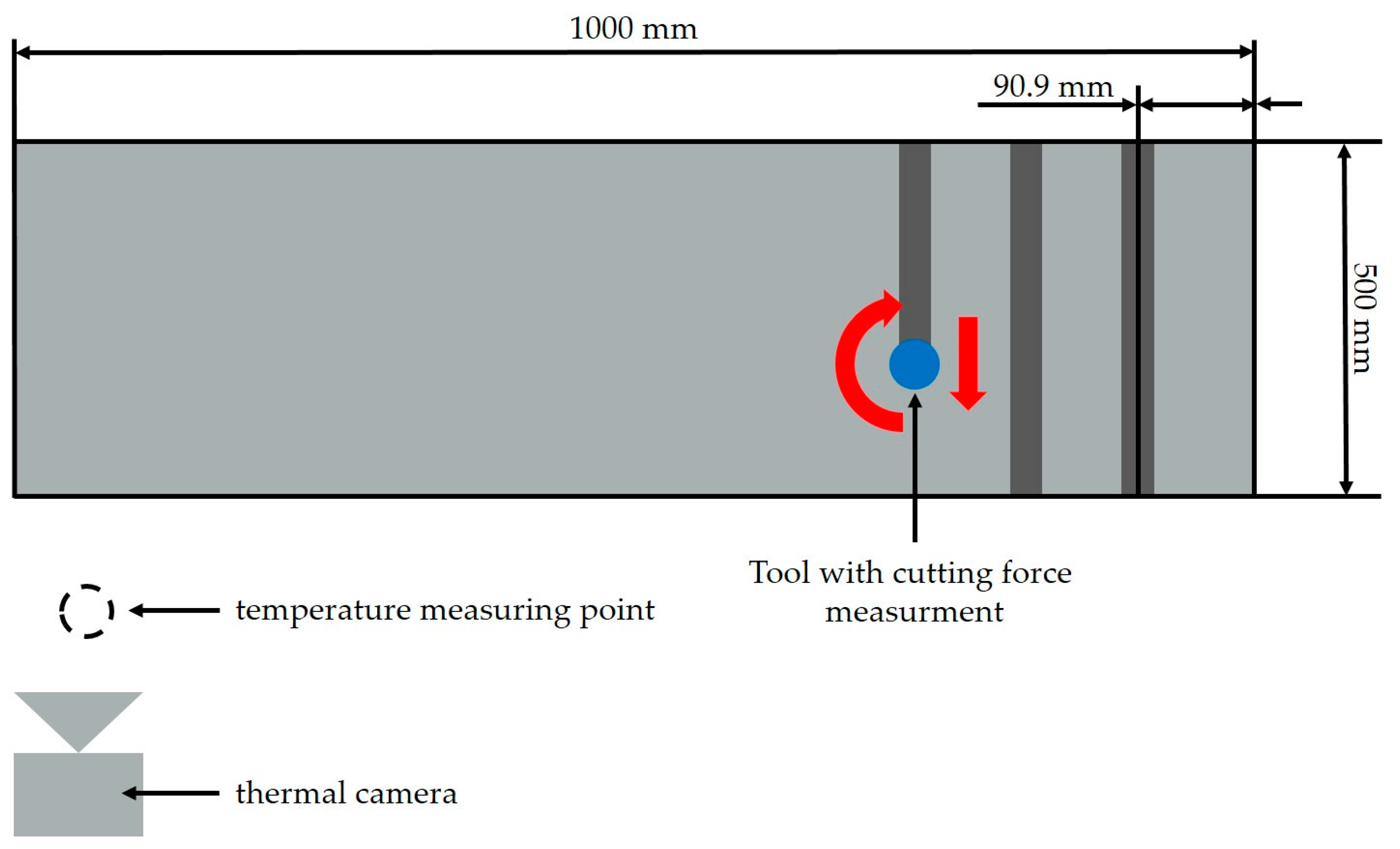
The experimental setup for notch milling is schematically illustrated in Figure 4. The notch milling tests were used to evaluate the effect of tool wear on cutting forces and process temperatures, enabling a comparison between the adhesively bonded and soldered tools.
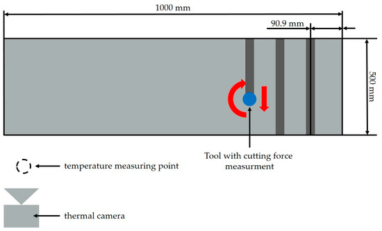
Figure 4.
Notch milling setup.
To measure the tool temperature under comparable conditions, a specific measurement point was determined. The temperature was measured after one notch, three notches, five notches, and ten notches.
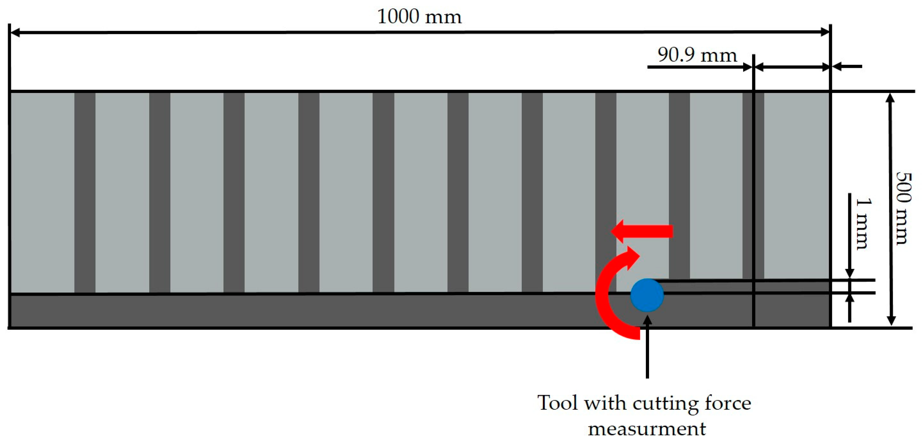
After milling ten notches, the entire fiberboard was beveled by rebate milling. The setup of this approach can be seen in Figure 5. For the evaluation of tool wear, the tool underwent optical examination, and changes in the cutting edge radius of the tool were determined. The wear was investigated at defined cutting distances, specifically at 0 m, 10 m, 30 m, 60 m and 100 m cutting distance. After 100 m up to 500 m, the wear was examined every 50 m, and from 500 m to 1000 m every 100 m.
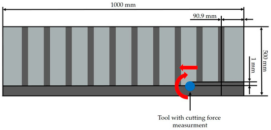
Figure 5.
Generating wear by radial milling.
3. Results
This chapter is divided into three sections. The first section, tool wear progress, considers the results of the wear generated by rebate milling. The second and third section only take into account the results of the notch tests.
3.1. Tool Wear Progress
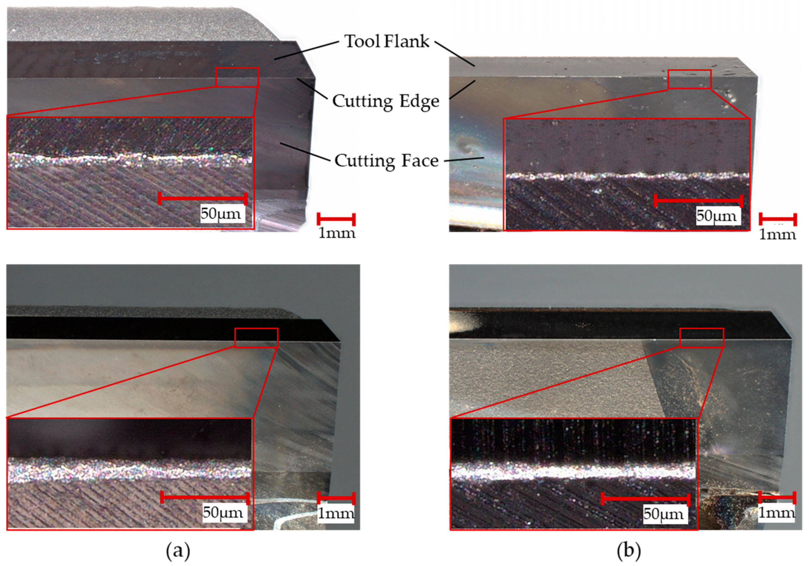
The adhesively bonded cutting tool as well as the soldered tool were investigated before and after notch milling. Each image taken with the light microscope shows the tool flank, cutting face, and cutting edge. Thereby, the wear of both tools was analyzed visually and compared to each other.
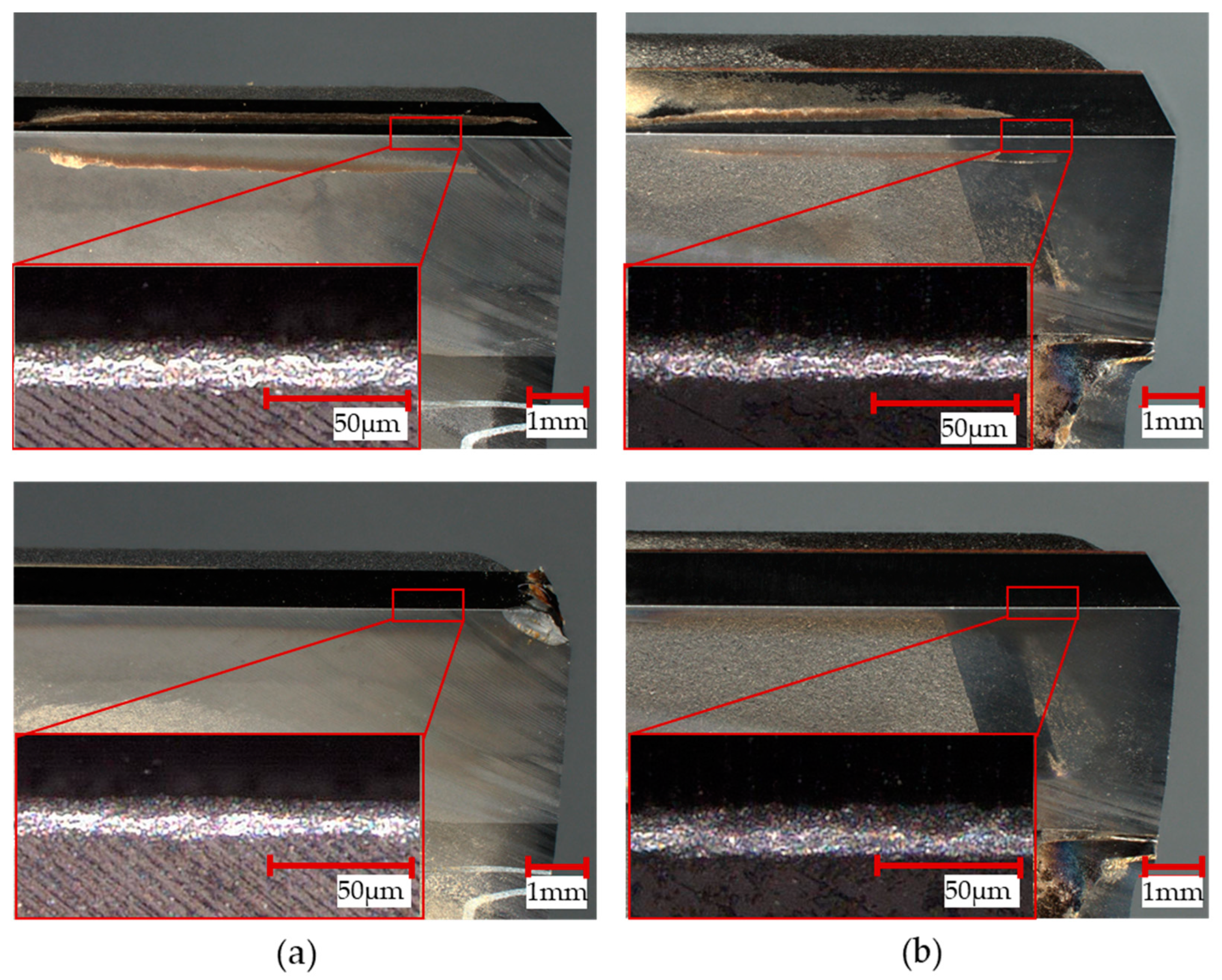
In Figure 6, the top of the image shows both cutting tools when new. The adhesively bonded tool is depicted on the top left-hand side (a), while the soldered tool is presented on the top right-hand side (b). Comparing the tools’ characteristics (tool flank, cutting face, and cutting edge), it can be seen that there is no visible difference in the cutting edge of the tools when new. Additionally, the images at the bottom show both tools after milling ten notches in a row. The images do not reveal any traces of wear. In addition, the details do not show significant differences between the two tools.

Figure 6.
New tools (top) and tools after 10 notches (bottom): (a) adhesively bonded; (b) soldered.
Images of the tools after rebate milling (top) and notch milling for the second time (bottom) are presented in Figure 7. The tool life after rebate milling was approximately 500 m.

Figure 7.
Tools after 500 m (top) cutting length and the second set of notch milling (bottom): (a) adhesively bonded; (b) soldered.
Both tools, the adhesively bonded and the soldered one, show material adherence after rebate milling and a tool life of 500 m. Other than that, there is no visible wear. After the second set of notch milling, material adherence came off. However, the adhesively bonded cutting tool shows a small disruption in the corner, whereas the soldered tool still did not exhibit any visible wear. The detailed view shows no visible differences until this point either.
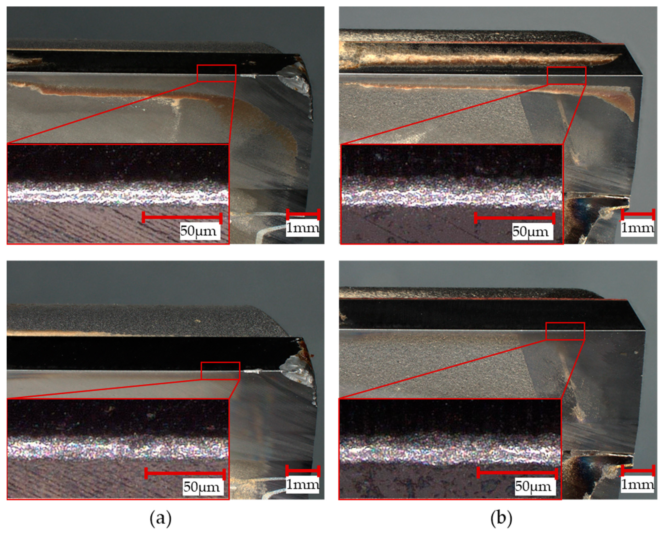
Images of the tools after rebate milling (top) and notch milling for the third time (bottom) are presented in Figure 8. The tool life after rebate milling was approximately 1000 m.
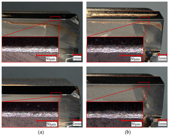
Figure 8.
Tools after 1000 m cutting length (top) and the third set of notch milling (bottom): (a) adhesively bonded; (b) soldered.
Both tools, the adhesively bonded and the soldered one, show material adherence after rebate milling with a tool life of 1000 m. The disruption at the edge of the adhesively bonded tool increased slightly on the tool flank. Furthermore, there is an additional disruption on the cutting edge. The soldered tool does not show any visible wear.
After the third set of notch milling, material adherence came off again. The disruptions in the adhesively bonded tool increased slightly. The soldered tool still shows no visible wear. In the detailed view, it looks like the cutting edge of the soldered tool is slightly more worn out than that of the adhesively bonded tool.
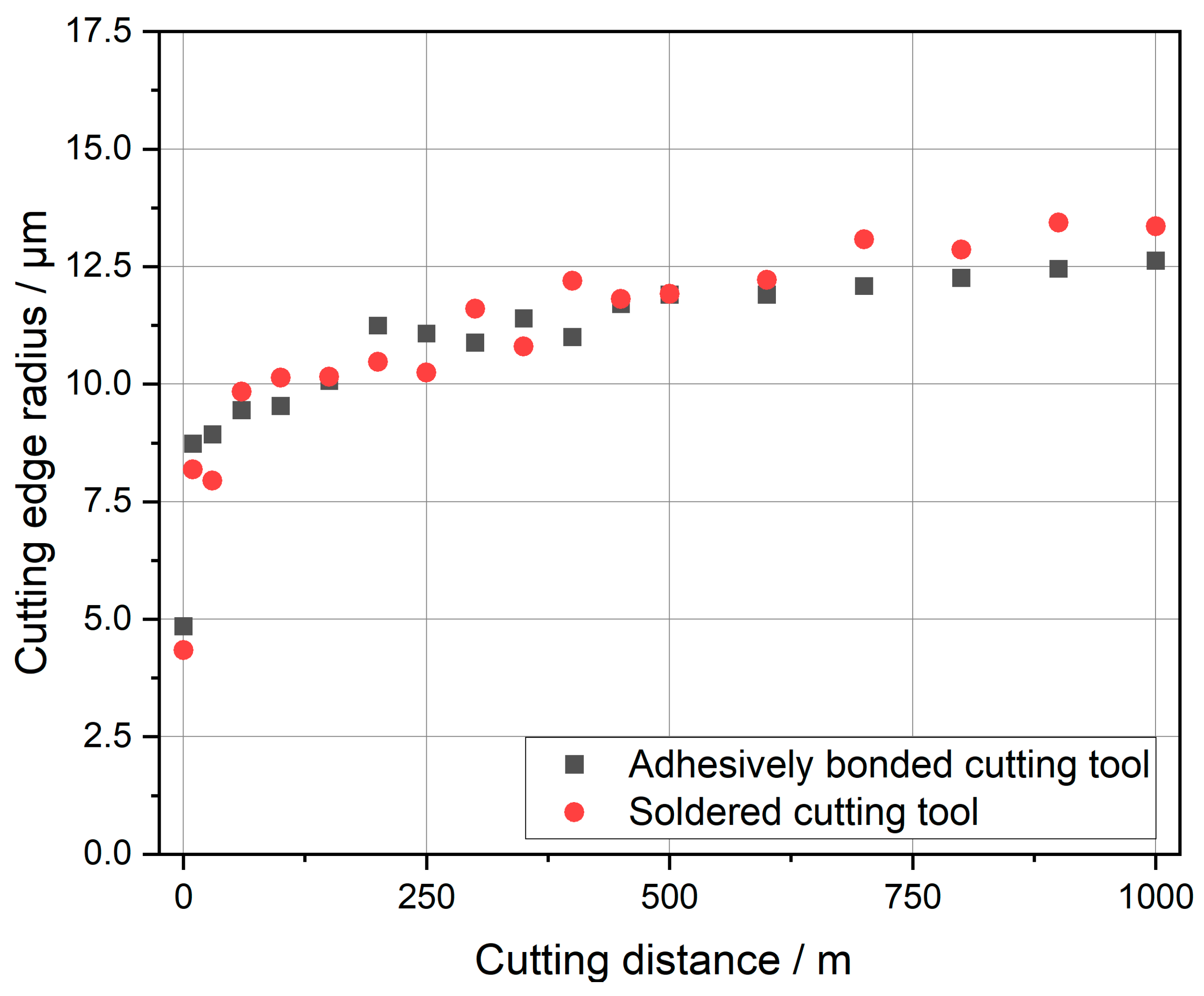
For further evaluation of tool wear, the development of the measured values of the cutting edge radius will be presented. The cutting edge radius was always measured at locations with no visible disruptions. For each tool, the cutting edges of both cutting inserts were considered and the mean value calculated. At the beginning of the test series, the cutting edge radius was 4.85 µm for the adhesively bonded tool and 4.3 µm for the soldered tool. Despite the small difference in cutting edge radius between both tools, they can still be compared in the context of this work.
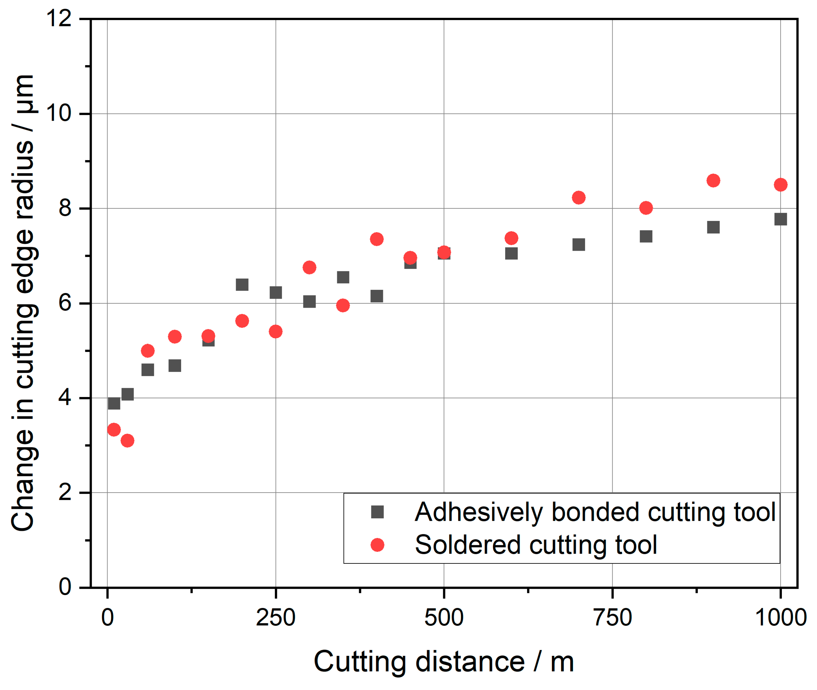
In Figure 9, the measured cutting edge radius is displayed. Both tools show a rising of the radius in a similar manner. Within the first few meters, the cutting edge radius changes very strongly. Starting at 100 m, the progression is almost linear. From a cutting distance of 400 m onward, the soldered tool consistently has a bigger cutting edge radius than the adhesively bonded tool. At the end of the experiments, the cutting edge radius for the soldered tool is noticeably higher. After 1000 m of cutting distance, the cutting edge radius of the soldered tool is 13.4 µm, and that of the adhesively bonded tool is 12.6 µm. The soldered tool experienced an increase of 8.5 µm in the cutting edge radius, while the adhesively bonded tool’s cutting edge radius only increased by 7.7 µm. For a simple comparison, Figure 10 shows the absolute change in cutting edge radius over the cutting distance.
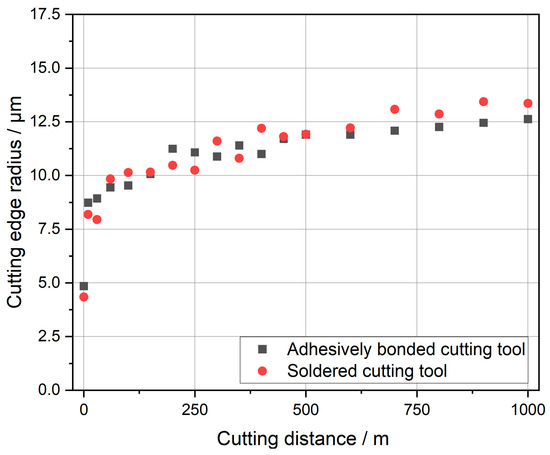
Figure 9.
Comparison of the cutting edge radius between the adhesively bonded and soldered cutting tools.
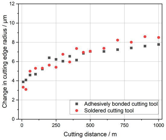
Figure 10.
Comparison of the change in cutting edge radius between adhesively bonded and soldered cutting tools.
3.2. Tool Temperature
For all of the following results, only the notch milling tests were taken into account.
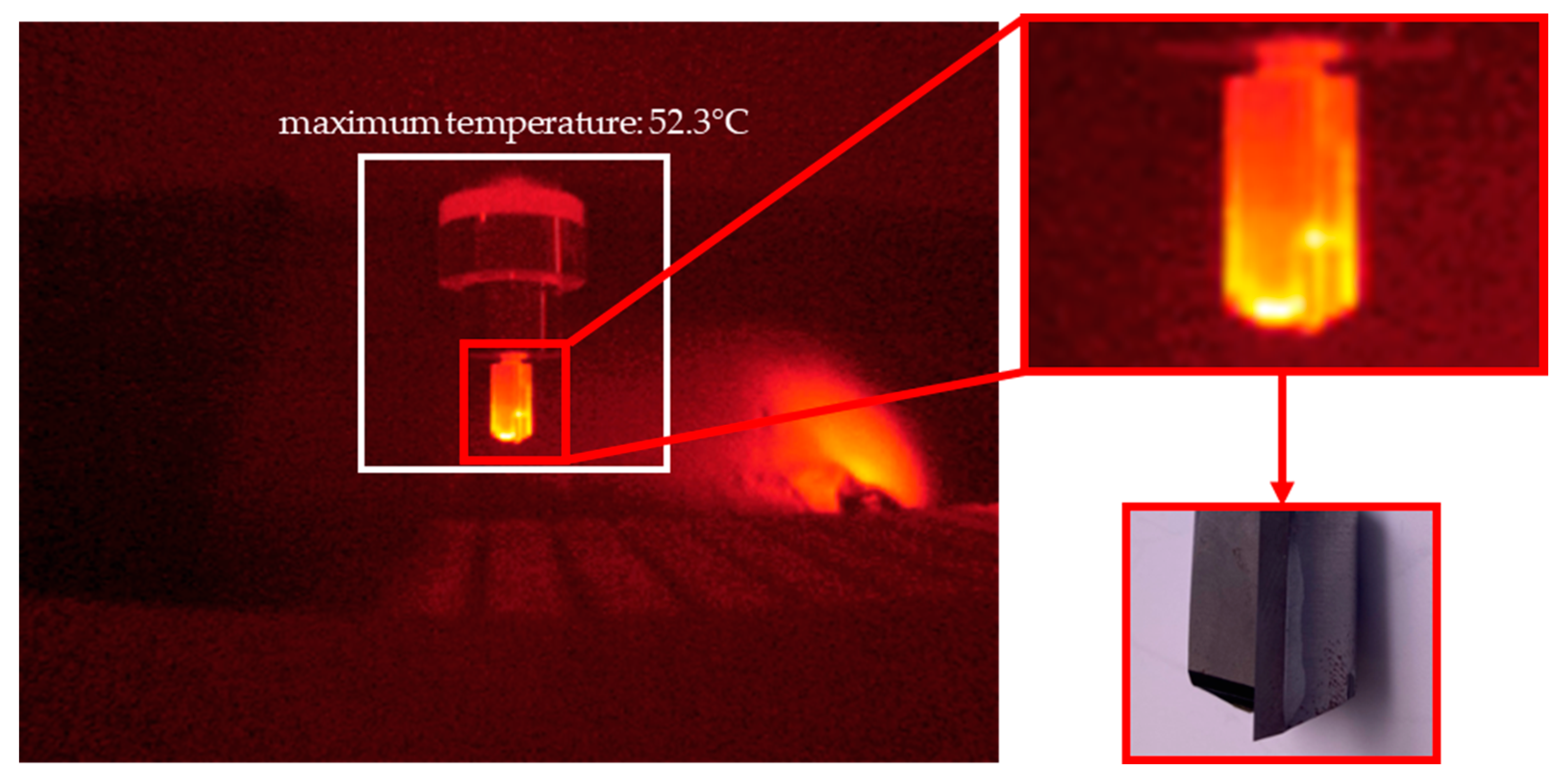
The temperature-measuring device operating with Optris PIX Connect Software (Optris GmbH, Berlin, Germany) always determined the highest temperature at the measuring point. The tool remained stationary for five seconds during temperature measurement. Yet, the measurement was not conducted at the exact same position. An example is pictured in Figure 11. In the portrayed white frame, the software determined the maximum temperature which was used for further evaluation. It can be seen that the tool heats up the most at the tip (which has the brightest color). A difference between the tool body and the carbide insert cannot be seen in the image.

Figure 11.
Temperature measurement of the tool after a set number of notches with a detailed picture of the heated tool (upper right) and a picture of the tool with the orientation (down right).
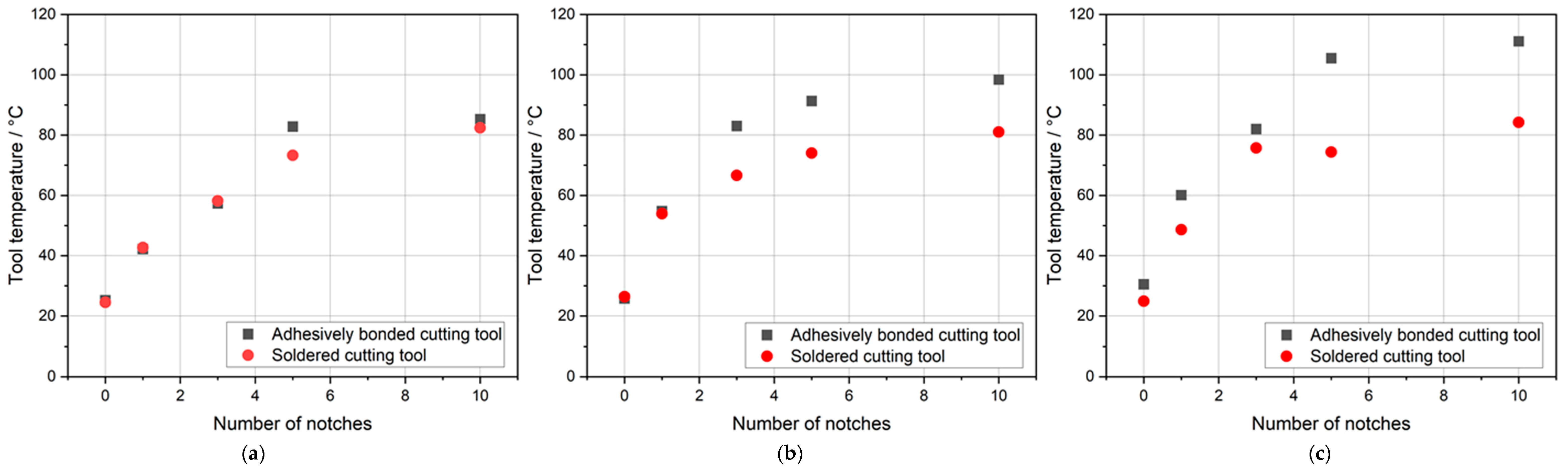
The results of the temperature measurements of the notches are shown in Figure 12. For the soldered tool, the temperature increase with every notch is almost comparable for all cutting distances. The difference lies within the first three notches. It is noticeable that with increasing cutting distance, the temperature within the first three notches rises faster. However, after ten notches, the tool temperature is similar for all cutting distances. For the new tool, it was 82.4 °C, after 500 m cutting distance, it was 81.0 °C, and after 1000 m cutting distance, it was 84.2 °C.
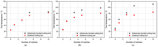
Figure 12.
Comparison of tool temperature for the notch tests with new tools (a): after 500 m (b); and after 1000 m (c) of cutting distance.
For the adhesively bonded tool, the results are different. The temperature rises in a similar manner to that of the soldered tool for the first cycle. However, it results in a slightly higher temperature after ten notches. At the beginning of every cycle, the starting temperatures for the adhesively bonded and soldered tool are similar, but after a few notches, they drift apart. The drift starts earlier with higher cutting distances. Additionally, the end temperature after ten notches for the adhesively bonded tool rises each time. For the new tool, it was 85.3 °C, 98.4 °C after a 500 m cutting distance, and 111.1 °C after a 1000 m cutting distance.
3.3. Torsional Moment
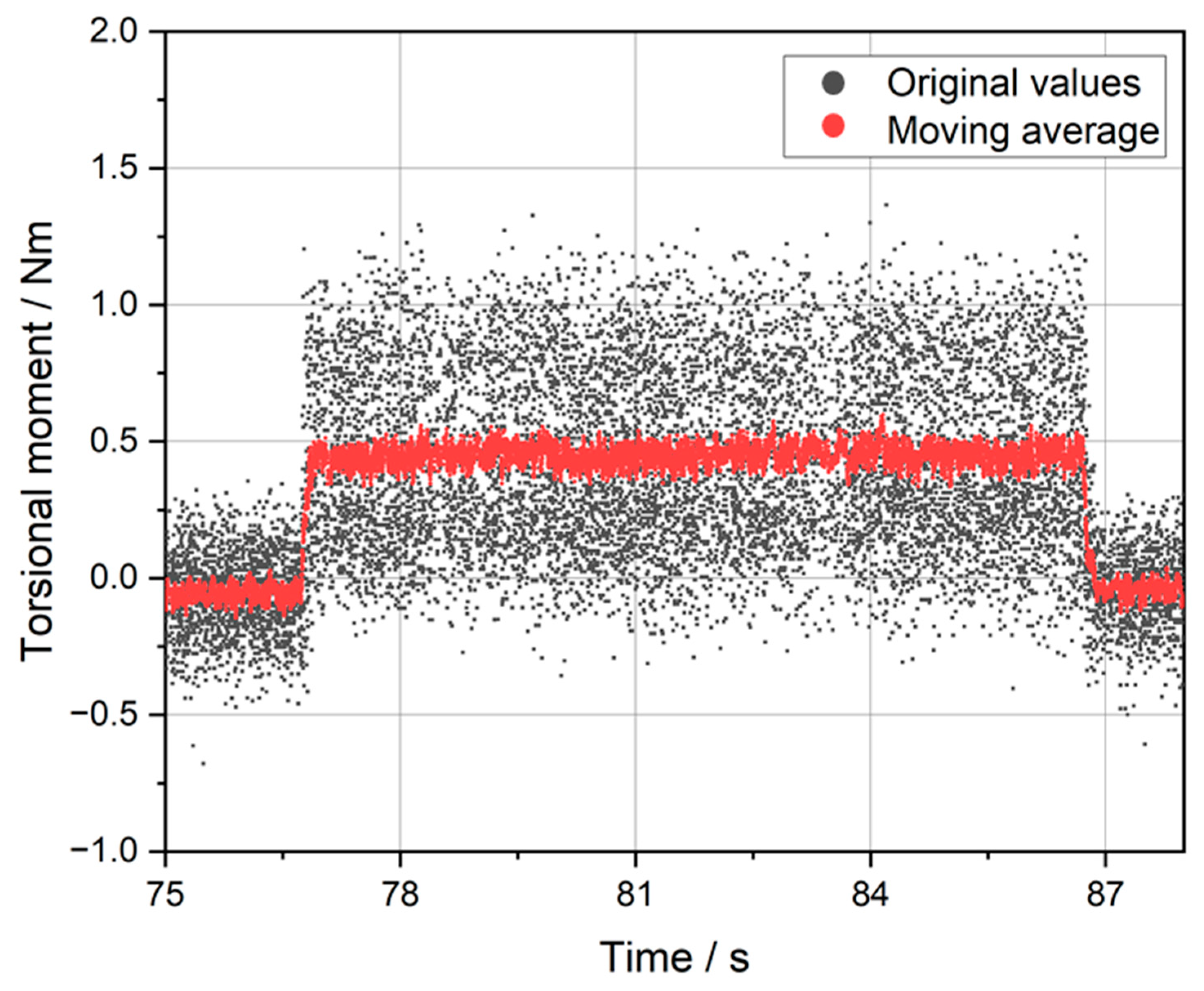
For the analysis of the torsional moment, the data measured with the Spike tool holder were analyzed. During the notch-milling process, the torsional moments were determined. An example of measured torsional moments while milling a notch can be seen in Figure 13. Despite the presence of a significant degree of noise, the region corresponding to the notch is distinctly visible within the diagram. The notch starts when the torsional moment rises above 0.5 Nm and ends when the moment falls below 0.5 Nm. For better readability, a moving average (10 values before and after the set point) is additionally shown in the graph. The diagram shows how the area of interest in which cutting of notches was performed was identified. It also demonstrates that the torsional moments during notch milling did not experience a drift, neither rising nor descending, towards the end of the notch. Therefore, a mean value could be calculated to compare the different notches.
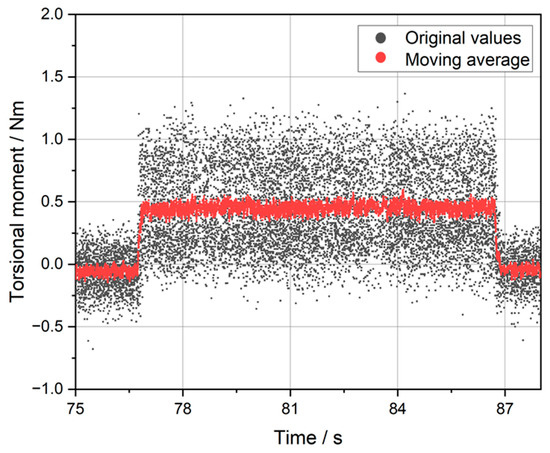
Figure 13.
The third notch of the adhesively bonded tool after a 500 m cutting distance.
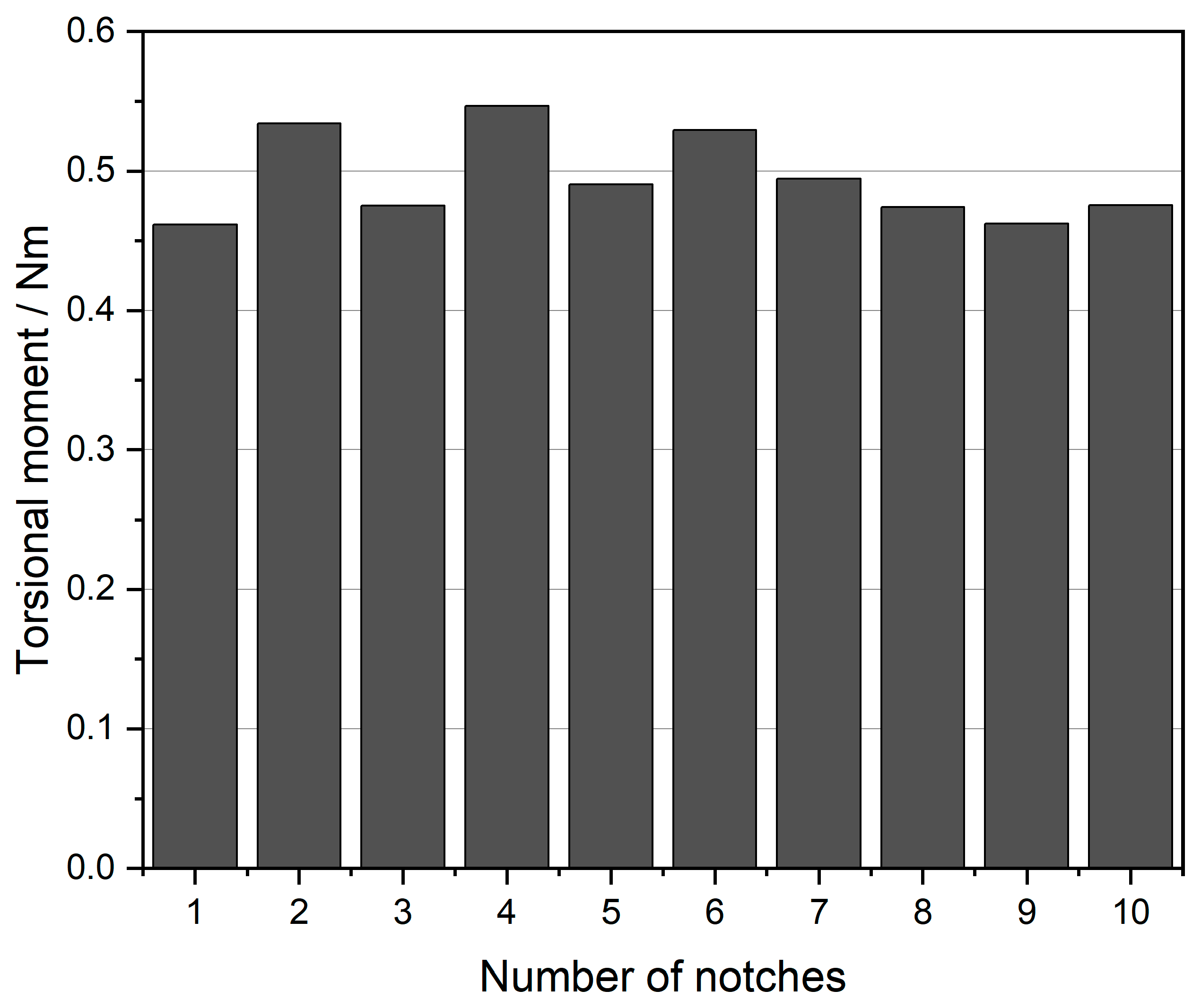
For the sake of clarity, the mean value was calculated for the corresponding regions to compare different notches. This process was repeated for every notch after every cutting distance. An example of torsional moments of ten notches after 500 m of cutting distance can be seen in Figure 14. It can be observed that the mean value fluctuates slightly between the notches. No other anomalies could be identified in any of the analyzed data.
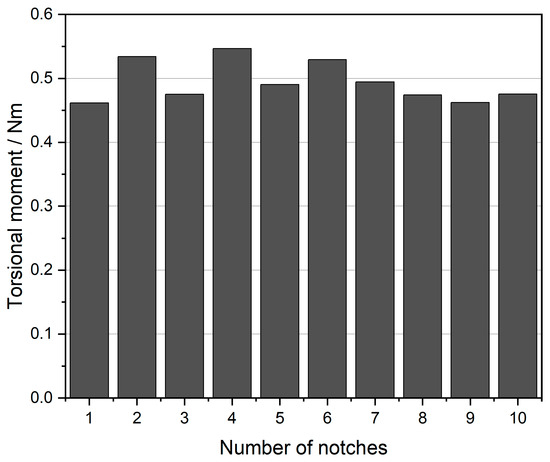
Figure 14.
Torsional moments for the ten notches of the adhesively bonded tool after 500 m of cutting distance.
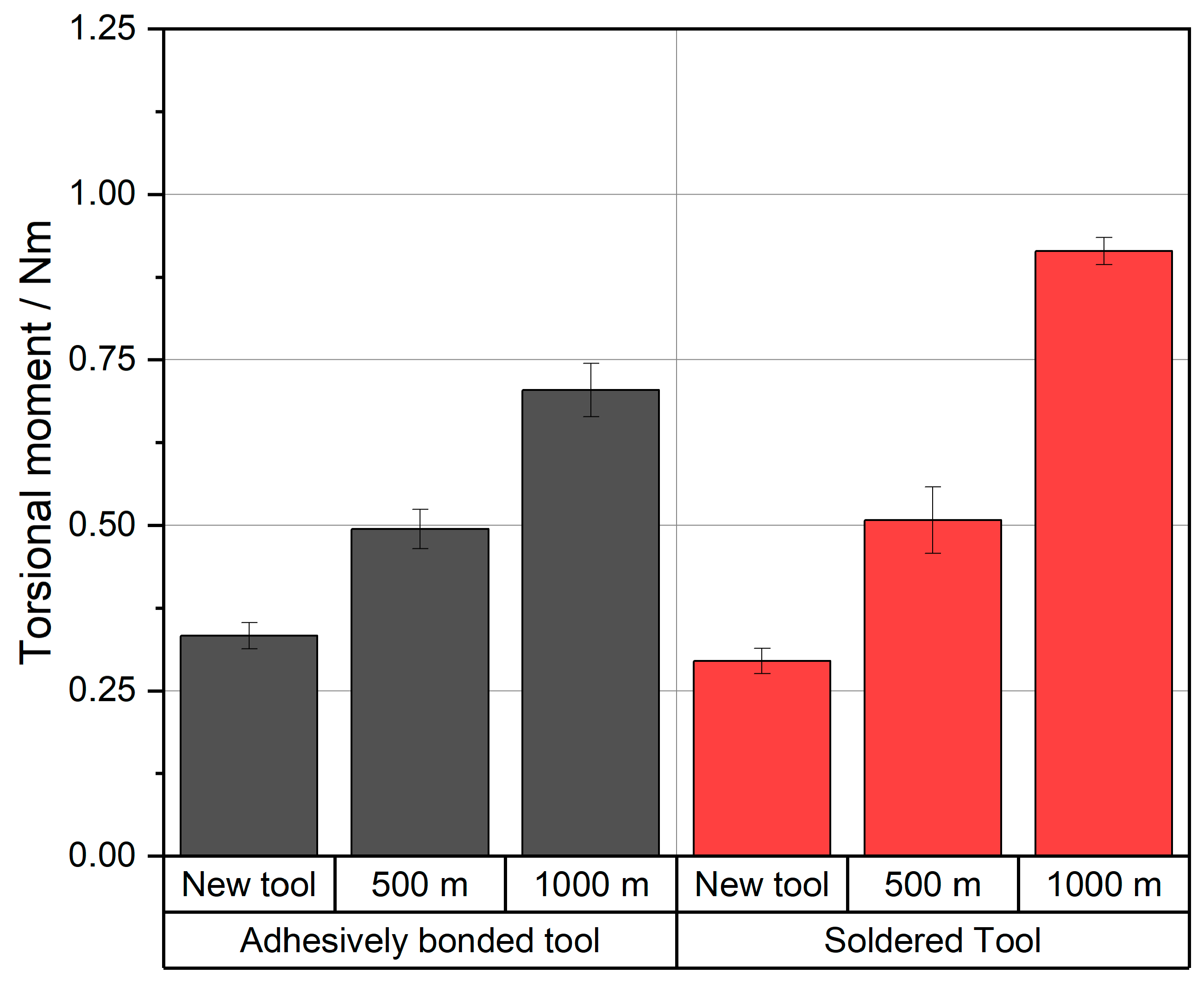
For better understanding of the development of the torsional moment over the cutting distance, the results of the individual notches were combined for each cutting distance and tool, and the mean average was calculated. The final result can be seen in Figure 15. It is noticeable that for the new tools and after 500 m of cutting distance, the torsional moments show similar results for the adhesively bonded and soldered tool. After 1000 m of cutting distance, the torsional moments for the soldered tool rose more than for the adhesively bonded tool.
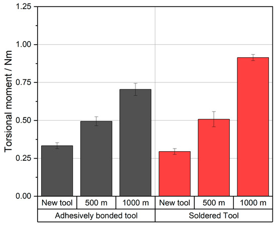
Figure 15.
Torsional moment for the ten notches of the new adhesively bonded and soldered tool after 500 m and 1000 m of cutting distance.
4. Discussion
For the discussion, the observations on the tool wear and the torsional moments were compared. Based on the optical investigations, it is notable that there are only disruptions on the adhesively bonded tool. However, it can also be observed that the torsional moments and the cutting edge radius are lower at the end of the tests than for the soldered tool. This observation suggests that the disruptions of the adhesively bonded tool are not a result of the adhesive bonding; there must be another explanation. For the authors, two possible reasons are considered:
- A material defect in the cutting edge was the origin of the disruption.
- There was an impurity in the MDF which broke the cutting edge.
After the tests, it is currently not possible to reconstruct which mechanism is responsible for the disruptions. Nevertheless, both explanations stated above are considered very likely.
The images of the cutting edge radius and the measured values of the cutting edge radius are consistent. The images show similar cutting edge radii with new tools and after 500 m with notches. These are comparable to the results of the measurement. After 1000 m, a slightly higher cutting edge radius at the soldered tool can be seen in the images as well as in the values. The small volatility in the values could result from not having the exact same measurement position each time.
The dissimilar growth in cutting edge radius can be explained by the damping effects of the adhesive. This kind of wear is independent of the disruptions. Therefore, the cutting edge radius is suitable for making a comparison between the two bonding processes. Due to the damping of the adhesive, the cutting forces are lower, resulting in a slower growth of the cutting edge radius. Consequently, at the end of the cutting distance, a lower cutting edge radius can be observed in the adhesively bonded tool. These results align with the observations of Darwish et al. [17] and Jachak et al. [18] in metal cutting.
For the comparison of the cutting edge radius and the torsional moments Table 2 can be used. Here, the values for each set of notches can be seen and compared. For comparison between the tools, the ratio between torsional moment and cutting edge radius was calculated.
Table 2.
Comparison between the cutting edge radius and the torsional moments of both tools.
It can be seen that for the set of notches with the new tool and after 500 m, the ratio is similar. Therefore, for both states of wear, both tools showed the same magnitude of torsional moments. This becomes evident when examining the individual values. However, a shift occurs after 1000 m, where the soldered tool exhibits a significantly higher ratio. Compared to the adhesively bonded tool, it has a higher torsional moment as well as a higher cutting edge radius. Therefore, it can be asserted that torsional moments largely depend on the cutting edge radius. Considering this and the previous studies on adhesively bonded tools, it can be assumed that damping effects lead to slower wear progression due to lower cutting forces. This again results in lower torsional moments for 1000 m tool life, which can be seen in the results of the conducted experiments.
Upon closer examination of the tool temperature for both tools, it is evident that the final temperature of the adhesively bonded tool after each set of ten notches is consistently higher than that of the soldered tool. This observation also holds true for the new tools under similar wear conditions, where no disruptions were encountered in either tool. However, the difference in temperature for the new tools is only minimal. In consideration of the results of Al-Samhan [23] and Usyal et al. [20], it seems like the adhesive layer is functioning as an insulator. Therefore, there are slightly higher temperatures in the adhesively bonded tool at the beginning of the tests. The disruptions in the adhesively bonded tool intensify this effect. After observing the tool temperature at the notches after 500 m cutting distance, it is assumed that the tool was damaged during machining the third notch. The assumption is based on the rapid increase of the tool temperature after the third notch and during the last set of notches. Before that, the temperatures were similar to the soldered tool and only minimally different.
The temperatures in the soldered tool also rise faster with increasing cutting distance. Yet, the maximal temperature is similar each time since the tool develops a steady state due to the better thermal conductivity. To support the assertions in this paper, repeating the test series with undamaged tools and a higher number is recommended. Additionally, it is reasonable to carry out tests with a higher cutting distance. Considering longer cutting distances, a cooling concept for woodcutting becomes crucial. Different authors [28,29,30] suggested cryogenic cooling is a promising cooling process for milling continuous fiber-reinforced thermoplastics, showcasing a significant reduction in tool wear. However, further research is needed. Chen et al. [29] observed an increase in surface roughness in comparison to dry cutting, while Agrawal et al. [30] and Zhang et al. [28] reported a reduction in surface roughness. Here, the process can be optimized. From the authors’ point of view, cryogenic cooling could also be a viable cooling concept for woodworking. To ensure the success of the concept, it is imperative that the adhesive does not become brittle and the wooden work piece does not become damaged due to the cryogenic cooling. Tests are necessary to validate this hypothesis, with jet temperature being a key parameter for the use of adhesively bonded cutting tools.
Maximizing the advantages of adhesively bonded cutting tools involves optimizing the bonding area in terms of damping effects. By doing so, it may be possible to minimize tool wear through the optimization of force flow within the cutting tool. To explore the possibilities of combining other cutting materials than those currently used, it is possible to investigate adhesively bonded ceramics for wood cutting. The usability of ceramics for wood cutting has been shown by different authors [4,14,15].
5. Conclusions
In the following section, the research issues expressed at the beginning are addressed.
- Are adhesively bonded tools suitable for cutting MDF?
The experiments demonstrate that adhesively bonded milling tools are indeed suited to the cutting of medium-density fiberboards as well as soldered tools.
- Are there noticeable differences in tool wear?
Noticeable differences in tool wear were observed between the adhesively bonded and the soldered tool: the adhesively bonded tool experienced a slower increase in cutting edge radius than the soldered one. After a cutting distance of 1000 m, the cutting edge radius of the soldered tool was 311% higher (from 4.3 µm to 13.4 µm) than it was at the beginning of the experiments, while the cutting edge radius of the adhesively bonded tool only increased by 257% (from 4.9 µm to 12.6 µm). The slower rise in the cutting edge radius of the adhesively bonded tool is attributed to damping. Although material disruptions were also detected in the adhesively bonded tool during the second round of notches, this appears to result from a non-adhesive bonding-related effect.
- Are there any noticeable differences in process temperatures and forces?
There are noticeable differences in process temperatures as well as in cutting forces between adhesively bonded and soldered tools. Both tools experienced a rise in temperature with progressing cutting distance. However, the rise in temperature for the adhesively bonded tool was considerably higher than that for the soldered tool. The main reason for this is the disruption encountered in the second set of notches. Additionally, the adhesive layer, acting as an insulator, has an amplifying effect on tool temperature. On the other hand, torsional moments for the soldered tool exceeded those of the adhesively bonded tool. This phenomenon is mainly due to the damping effect in the adhesively bonded tool and the resulting smaller cutting edge radius. Still, it is known that disruptions in the cutting edge also tend to affect torsional moments. Therefore, it is recommended to repeat investigation tests with several new tools without disruptions for a secure analysis. Nevertheless, this work’s results align with current literature on this subject.
In conclusion, it can be established that for short cutting distances in wood machining, higher temperatures in adhesively bonded tools do not have a significant impact on either tool wear or torsional moments. Therefore, it can be concluded that adhesively bonded tools offer a promising alternative for soldering. However, achieving success in the cutting industry demands additional research and development.

Author Contributions
Conceptualization, S.S. and R.P.; methodology, S.S.; investigation, S.S.; resources, S.S.; writing—original draft preparation, S.S. and R.P.; writing—review and editing, S.S. and R.P.; visualization, S.S.; supervision, S.S.; project administration, S.S.; funding acquisition, S.S. All authors have read and agreed to the published version of the manuscript.
Funding
This research project “DuoDrill” was funded by the Ministry of Economics, Labour and Tourism of Baden-Württemberg, as part of the funding program “InvestBW”, with the grant number BW1_1468/03.
Data Availability Statement
The data presented in this study are available on request from the corresponding author.
Acknowledgments
The authors wish to thank the companies Jakob Schmid GmbH + Co. KG and Himmelwerk Hoch- und Mittelfrequenzanlagen GmbH for their support and collaboration in the project “DuoDrill”.
Conflicts of Interest
The authors declare no conflict of interest.
References
- Dispan, J. Branchenanalyse Holzbearbeitungsmaschinenbau: Strukturen, Entwicklungstrens, Digitale Transformation, Beschäftigung und Perspektiven für die Branche; No. 265; Working Paper Forschungsförderung: Düsseldorf, Germany, 2023. [Google Scholar]
- Gottlöber, C. Zerspanung von Holz und Holzwerkstoffen: Grundlagen—Systematik—Odellierung—Prozessgestaltung; Fachbuchverl Leipzig/Hanser: Leipzig, Germany; München, Germany, 2014; ISBN 3446440585. [Google Scholar]
- KopacÏ, J.; Sali, S. Wood: An important material in manufacturing technology. J. Mater. Process. Technol. 2003, 133, 134–142. [Google Scholar] [CrossRef]
- Guo, X.; Wang, J.; Buck, D.; Zhu, Z.; Ekevad, M. Cutting forces and cutting quality in the up-milling of solid wood using ceramic cutting tools. Int. J. Adv. Manuf. Technol. 2021, 114, 1575–1584. [Google Scholar] [CrossRef]
- Pakzad, S.; Pedrammehr, S.; Hejazian, M. A Study on the Beech Wood Machining Parameters Optimization Using Response Surface Methodology. Axioms 2023, 12, 39. [Google Scholar] [CrossRef]
- Blugan, G.; Strehler, C.; Vetterli, M.; Ehrle, B.; Duttlinger, R.; Blösch, P.; Kuebler, J. Performance of lightweight coated oxide ceramic composites for industrial high speed wood cutting tools: A step closer to market. Ceram. Int. 2017, 43, 8735–8742. [Google Scholar] [CrossRef]
- Eblagon, F.; Ehrle, B.; Graule, T.; Kuebler, J. Development of silicon nitride/silicon carbide composites for wood-cutting tools. J. Eur. Ceram. Soc. 2007, 27, 419–428. [Google Scholar] [CrossRef]
- Chladil, J.; Sedlák, J.; Šebelov, E.; Kučera, M.; Dado, M. Cutting conditions and tool wear when machining wood-based materials. Bioresources 2019, 14, 3495–3505. [Google Scholar] [CrossRef]
- Muhammed, M.; Javidani, M.; Heidari, M.; Jahazi, M. Enhancing the Tribological Performance of Tool Steels for Wood-Processing Applications: A Comprehensive Review. Metals 2023, 13, 1460. [Google Scholar] [CrossRef]
- Pahlitzsch, G.; Sandvoß, E. Einfluß der Schnittbedingungen auf die Beanspruchung und den Verschleiß der Schneide. Holz Roh- Werkst. 1972, 30, 134–143. [Google Scholar] [CrossRef]
- Kminiak, R.; Němec, M.; Igaz, R.; Gejdoš, M. Advisability-Selected Parameters of Woodworking with a CNC Machine as a Tool for Adaptive Control of the Cutting Process. Forests 2023, 14, 173. [Google Scholar] [CrossRef]
- Piçarra, A.; Annesley, I.R.; Otsuki, A.; de Waard, R. Market assessment of cobalt: Identification and evaluation of supply risk patterns. Resour. Policy 2021, 73, 102206. [Google Scholar] [CrossRef]
- Bastian, D.; Brandenburg, T.; Buchholz, P.; Huy, D.; Liedtke, M.; Schmidt, M.; Sievers, H. Angebotskonzentration bei Mineralischen Rohstoffen und Zwischenprodukten—Potenzielle Preis- und Lieferrisiken: DERA-Rohstoffliste 2019; Datenstand: January 2019; DERA: Berlin, Germany, 2019; ISBN 978-3-943566-63-5. [Google Scholar]
- Guo, X.; Zhu, Z.; Ekevad, M.; Bao, X.; Cao, P. The cutting performance of Al2O3 and Si3N4 ceramic cutting tools in the milling plywood. Adv. Appl. Ceram. 2018, 117, 16–22. [Google Scholar] [CrossRef]
- Wei, H.; Guo, X.; Zhu, Z.; Cao, P.; Wang, B.; Ekevad, M. Analysis of cutting performance in high density fiberboard milling by ceramic cutting tools. Wood Res. 2018, 63, 455–466. [Google Scholar]
- Luhn, R.; Sändig, S.; Maul, T.; Geiß, P.L.; Gramsch-Kempkes, S. Geklebte Hartstoffschneiden. Adhäsion KLEBEN DICHTEN 2012, 56, 40–45. [Google Scholar] [CrossRef]
- Darwish, S.M.H.; Davies, R.G.H. Adhesive Bonding of Metal Cutting Tools. Int. J. Mach. Tools Manuf. 1989, 29, 141–152. [Google Scholar] [CrossRef]
- Jachak, S.; Giri, J.; Awari, G.K.; Bonde, A.S. Surface finish generated in turning of medium carbon steel parts using conventional and adhesive bonded tools. Mater. Today Proc. 2021, 43, 2882–2887. [Google Scholar] [CrossRef]
- Schneider, B.; Rütters, M.; Alder, J. Höhere Zerspanleistungen durch geklebte Bearbeitungswerkzeuge. Adhäsion KLEBEN DICHTEN 2020, 64, 38–44. [Google Scholar] [CrossRef]
- Uysal, A.; Eryildiz, E.; Altan, E. Turning Performance of Bonded Cutting Tools with Nanographene or Multi-walled Carbon Nanotube Particle-Reinforced Epoxy-Based Nanocomposite Adhesives. Arab J. Sci. Eng. 2019, 44, 7737–7752. [Google Scholar] [CrossRef]
- Stroka, M.; Stribick, S.; Kolb, M. Geklebte Keramiken im unterbrochenen Schnitt: Untersuchung zum Kreissägen von Grauguss mit geklebten keramischen Schneidstoffen. WT Werkstattstech. Online 2021, 111, 65–70. [Google Scholar] [CrossRef]
- Darwish, S.M.H.; Davies, R.G.H. Investigation of the heat flow through bonded and brazed metal cutting tools. Int. J. Mach. Tools Manuf. 1989, 29, 229–237. [Google Scholar] [CrossRef]
- Al-Samhan, A.M. Thermal-stresses in carbide-tip bonded face milling cutters. J. King Saud Univ.-Eng. Sci. 2012, 24, 85–94. [Google Scholar] [CrossRef]
- Correia, D.S.; Carbas, R.J.; Marques, E.A.; das Neves, P.J.; Da Silva, L.F. Experimental study on aluminium to tungsten carbide/polycrystalline diamond (WC/PCD) adhesive bonding for milling tools. Int. J. Adhes. Adhes. 2022, 114, 103121. [Google Scholar] [CrossRef]
- Correia, D.S.; Marques, E.; Carbas, R.; das Neves, P.; Da Silva, L. Numerical optimisation of bonded joints for the manufacture of edge milling tools. Eng. Fail. Anal. 2022, 134, 106012. [Google Scholar] [CrossRef]
- Gomes, P.N.; Correia, D.S.; Carbas, R.J.; Marques, E.A.; das Neves, P.J.; Afonso, W.P.; Da Silva, L.F. Development of productive curing processes for the manufacturing of adhesively bonded milling tools. J. Adhes. 2023, 1–22, ahead of print. [Google Scholar] [CrossRef]
- de Sousa, R.J.F.; Gomes, P.N.; Correia, D.S.; Carbas, R.J.C.; Marques, E.A.S.; das Neves, P.J.C.; Afonso, W.P.; da Silva, L.F.M. Analysis of the Mechanical Performance and Durability of Adhesively Bonded Joints Used in the Milling Tool Industry. Appl. Sci. 2023, 13, 4937. [Google Scholar] [CrossRef]
- Zhang, L.; Zhang, X. Effect of cooling and lubrication conditions on the variable angle milling of unidirectional CFRP with PCD tools. J. Mater. Process. Technol. 2023, 319, 118073. [Google Scholar] [CrossRef]
- Chen, X.; Zhao, W.; Zhao, G.; Jamil, M.; He, N. Tool wear and surface quality during milling CFRP laminates under dry and LN2-based cryogenic conditions. Int. J. Adv. Manuf. Technol. 2022, 123, 1785–1797. [Google Scholar] [CrossRef]
- Agrawal, C.; Khanna, N.; Pimenov, D.Y.; Wojciechowski, S.; Giasin, K.; Sarıkaya, M.; Yıldırım, Ç.V.; Jamil, M. Experimental investigation on the effect of dry and multi-jet cryogenic cooling on the machinability and hole accuracy of CFRP composites. J. Mater. Res. Technol. 2022, 18, 1772–1783. [Google Scholar] [CrossRef]
Disclaimer/Publisher’s Note: The statements, opinions and data contained in all publications are solely those of the individual author(s) and contributor(s) and not of MDPI and/or the editor(s). MDPI and/or the editor(s) disclaim responsibility for any injury to people or property resulting from any ideas, methods, instructions or products referred to in the content. |
© 2023 by the authors. Licensee MDPI, Basel, Switzerland. This article is an open access article distributed under the terms and conditions of the Creative Commons Attribution (CC BY) license (https://creativecommons.org/licenses/by/4.0/).