Abstract
The aim of this investigation is to offer a data-based scheme for predicting electrode wear in resistance spot welding. One of the major factors affecting the mechanical properties of spot welds and the variation in weld quality is electrode wear and alloying. In this study, Rogowski coils and twisted pairs attached to the top and bottom electrodes were used to obtain the welding current and the voltage between the electrodes in the welding process, thereby calculating the dynamic resistance value during the welding process. The electrode tip diameter was obtained from the pressure exerted by the upper and lower electrodes on the carbon paper when the current was cut off and was regarded as an indicator of electrode wear. By continuously welding 0.5 mm thick BH 340 steel plates until the electrode failed, the dynamic resistance signal was recorded in real time. Simultaneously, the electrode diameter after every several welds was also recorded. On this basis, the correlation between electrode tip diameter and dynamic resistance is studied. In order to quantitatively study the mapping relationship between dynamic resistance and electrode wear, 10 characteristic values were extracted from the dynamic resistance, and the stepwise regression method was used to obtain the regression formula between the characteristic values and the electrode tip diameter. Using new data to verify the effectiveness of the regression model, the acquired results display that the maximum error between the predicted value of the electrode tip diameter and the measured value obtained by the regression equation with the interactive quadratic term is 0.3 mm, and the corresponding relative error is 7.69%. When welding with a new pair of electrodes, the maximum absolute error was 0.72 mm, and the relative error of the model prediction is within 20% according to the linear regression model with interaction terms. This indicates that this regression model is barely satisfactory for monitoring electrode condition.
1. Introduction
In recent years, coated steel plates have been used in many industries because coatings can greatly improve the corrosion resistance of steel products [1]. Galvanised steel is the most common form of coated steel with usage increasing substantially. In car manufacturing, the use of zinc-coated steel sheet can prolong the life of the car body and improve its corrosion resistance. The most common joining technologies in the manufacturing process of the galvanised steel car body are friction stir welding, tungsten inert gas shielded arc welding, laser welding, metal inert gas shielded arc welding, self-piercing riveting, etc. [2]. Among them, resistance spot welding is the most frequently used because it has a high degree of automation suitable for large-scale mass production, simple operation and cost saving [3].
The resistance spot-welding process and the effect on electrode wear are completely different between galvanised and uncoated steel sheets [4]. Since the presence of the galvanised layer increases the conductivity of the steel sheet compared to the uncoated steel sheet, when the same welding process parameters are used to weld the galvanised steel sheet, the welding heat is obviously insufficient. It is therefore necessary to apply a higher welding current. The relatively high welding current and the electrode are prone to metallurgical reactions with the galvanised layer. In addition, the electrode is hot, and electrode wear is the major cause of electrode failure during alloying. Yet, in the actual production of car body welding, continuous welding is commonly used to enhance welding production efficiency, which accelerates electrode degradation. Studies have exposed that the size of the electrode tip can be a measure of the degree of electrode wear [5]. Then, after hundreds of welds, the electrode tip dimensions must be evaluated to determine the degree of degradation [6].
By producing 400 consecutive welds of galvanised TRIP steel, Mahmud et al. [7] explored the effect of electrode degradation on one such defect, Zn-enhanced liquid metal embrittlement (LME) cracking, in resistance spot welding. The main factor influencing LME cracking was confirmed to be geometric degradation, specifically the radius of curvature. Metallurgical degradation had no effect on LME cracking in the first 200 welds as its influence was overcome by geometrical degradation. Electrode deterioration in continuously welded baked hardening (BH) 220 steel was analysed by Zhao et al. [8]. They tested electrode life and weldability by measuring geometric features, analysing mechanical properties and checking the electrode tip diameter at 88 or 176 weld intervals. Zheng et al. [9] studied the failure process of oriented multi-walled carbon nanotube-reinforced copper-based composite electrodes by analysing the macro/micro-morphology, microstructure, hardness, texture and composition. The results show that the life of the composite electrode is three times longer than that of conventional CuCrZr electrodes, and the degradation rate is much slower. Previous researchers have studied the process of electrode failure and the effect of this phenomenon on weld quality, but there are still few studies on the prediction and monitoring of electrode wear. Mathiszik et al. [10] investigated whether electrode life could be further extended by assessing in situ or in-line wear during the welding process without the use of additional sensors and determining the timing of tip trimming based on continuous process monitoring. In this case, they analysed electrode wear by topography measurements under laboratory conditions to gain an understanding of the known main wear modes of resistance spot welding electrodes, mushroom and plateau formation, and to characterise electrode length increments as a function of the number of spot welds. The relationship between welding process signals such as dynamic resistance and electrode displacement signals and electrode wear has recently attracted the attention of some researchers. Ibáñez et al. [11] proposed a real-time monitoring method based on data collected from the actual welding production line when the spot-welding electrode wears to a certain degree and requires milling. The unsupervised clustering method is used to process and analyse the welding current and resistance data to classify the degree of electrode wear. Zhou et al. [12] used the changing pattern of dynamic resistance during spot welding as the number of welding points increases, and they qualitatively studied the relationship between dynamic resistance changes and electrode wear status. However, researchers have not further studied the quantitative relationship between them. Panza et al. [13] envisaged using a medium-frequency direct current resistance spot welding machine and some sensing equipment to collect the electrode tip diameter, the contact area between the electrode and the weldment, and the electrode displacement curve. These data can be used to build a model based on machine learning algorithms to predict the wear of the electrode and the number of welds. Panza et al. [14] built an artificial neural network model using the feature values extracted from the electrode displacement signal as the input to the model, and the predicted value of the model was the contact area between the electrodes and the steel sheets. The model successfully predicted electrode wear and degradation. In actual production, the assessment of electrode wear often relies on the actual experience of the welders for a qualitative assessment. There are few quantitative studies of electrode wear based on the dynamic resistance signal.
BH steel plates are widely used in car bodies. Research has also been published on the welding characteristics of BH steel plates [15,16,17]. The degree of electrode wear has a non-negligible effect on the strength of resistance spot welded joints of BH steel plates. The dynamic resistance is a key signal in resistance spot welding and is closely related to weld quality [18]. However, research into the relationship between the dynamic resistance signal and spot-welding electrode wear is still at a preliminary stage, and relevant quantitative research is even rarer. In this study, resistance spot welding experiments were carried out on 0.5 mm thick BH 340 steel plates until the electrode failed. At the same time, dynamic resistance signals and electrode diameter changes are collected. In addition, the evolution of the dynamic resistance with electrode wear will be studied, and models to predict electrode wear will be developed. In this way, the purpose of monitoring electrode wear through the dynamic resistance signal during the continuous welding process is achieved.
2. Experimental Procedure
Experimental Materials and Welding Conditions
A BH340 galvanised steel plate, 0.5 mm thick, is used as the welding material in the welding experiment. Table 1 provides the chemical composition and mechanical properties of the steel plate and the composition of the coating.

Table 1.
Chemical compositions and mechanical attributes of BH 340 and the coating (%).
The medium frequency direct current (MFDC) resistance spot welding machine is used to weld steel plates [19], and the welding mode is a constant current mode. In order to reduce the effect of stains on the surface of the steel plate upon the welding quality, the steel plate must be mechanically and chemically cleaned before welding. First of all, the steel plate should be wiped several times with industrial alcohol, then rubbed with a clean, damp cloth, and left to dry in a well-ventilated place. As the thickness of the steel plate is extremely small, the post-weld cooling method is air cooling. The tip diameter of the electrode is 3 mm, and its material is Cu-Cr-Zr alloy. The electrodes belong to type A pointed welding electrodes [20]. Figure 1 shows the electrode dimensions in detail. Table 2 shows the material properties of the electrodes.
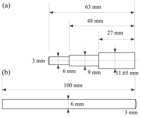
Figure 1.
Geometry of the electrodes: (a) the upper electrode; (b) the lower electrode.

Table 2.
Electrode material parameters.
In order to inspect electrode wear, it is essential to select appropriate spot-welding process parameters and repeat the welding operations. When implementing continuous welding on two large stacked steel plates, certain measures must be taken to reduce the adverse effect on the weld quality caused by welding current shunting. In actual operation, the distance between the welding points and the edge of the welding plate is set at 20 mm in order to save the consumption of welded steel plates and to minimise the effect of current shunt on the welding quality [21]. Figure 2 shows the layout of the welding points. The welding current during the welding process is 4.0 kA, which is slightly lower than the critical welding current when expulsion occurs to ensure weld quality. The other welding process parameters are listed in Table 3. All the procedures for the welding operation are based on the work carried out previously [19]. The specific waveform of the welding current is shown in Figure 3.

Figure 2.
Distances between edges and welds on the plates.

Table 3.
Schematisation of the spot weld schedule used in the experimental runs.
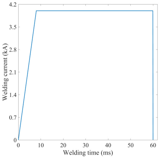
Figure 3.
The welding current waveform.
For continuous spot welding, dynamic resistance signals are recorded in real time. The schematic diagram of measuring the welding current and voltage between the electrodes in resistance spot welding is shown in Figure 4. Figure 5 shows the test system for measuring current and voltage during welding. The Rogowski coil is employed to measure the welding current value during the welding process [22], while the voltage between the top and bottom electrodes is simply obtained using the alligator clip cable [23]. The acquired signal must be converted from analogue to digital and input to the oscilloscope for display. The signal can be output via the oscilloscope’s USB interface and copied to the computer for further processing.
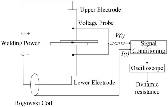
Figure 4.
Schematic diagram of the measurement of welding current and voltage between electrodes.
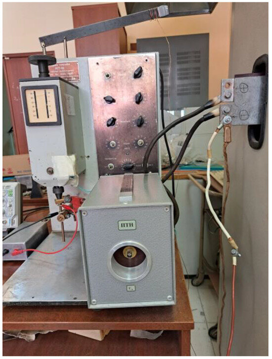
Figure 5.
The measurement system of the dynamic resistance.
During continuous welding, the carbon paper was utilised to record the changes in diameter of the electrode tip after several welding points. When recording the geometric dimensions of the electrode tip by means of carbon paper, we used the same welding process parameters as for the actual welding, except that the welding current must be switched off at this point. The resulting electrode indentation was then placed under a low-magnification light microscope and its geometric dimensions were measured. Figure 6 shows the electrode diameter when welding 20 points. Overall, 176 welds were welded and the electrode tip diameter was recorded, resulting in 43 sets of data. It should be noted that the electrode tip diameter is not recorded after a fixed number of welds. This is because it was found that the electrode tip diameter increased more at the beginning and then tended to increase slowly [14]. In this case, the electrode tip diameter was measured more frequently in the first half of these 176 spot welds. The majority (75%) of the total data was used to establish the regression models, while the rest was used to check the performance of the models in predicting the electrode tip diameter.
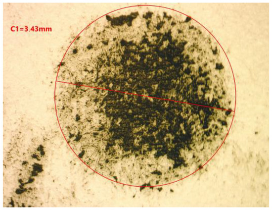
Figure 6.
The measurement of the electrode diameter for the 20th weld.
3. Experimental Results and Discussion
3.1. Diameter of the Electrode Tip
The electrode tip diameter was obtained by copying the electrode imprint onto the carbon paper. First, we used a low-magnification optical microscope to obtain a magnified image of the electrode imprint. Then, the electrode tip diameter was obtained by measuring its image, and it was used to characterise the failure process of the electrode. Figure 7 shows the changing trend of the electrode tip diameter as the number of welded joints increases.
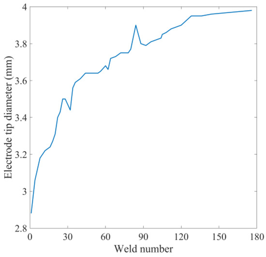
Figure 7.
The changing trend of electrode tip diameter with the number of welds.
Because the electrode is at high temperature for a long time and high electrode pressure must be applied to the weld plates, the electrode is prone to plastic deformation as the number of weld points increases. This phenomenon is accompanied by a gradual increase in the electrode tip diameter [9]. Firstly, the variance of the change in diameter of the electrode tip is small and increases at a high rate. Secondly, as the pitting corrosion on the electrode surface becomes more apparent, the change in electrode tip diameter is more dramatic, but the growth rate decreases.
3.2. Dynamic Resistance Signal Characteristics
Figure 8 and Figure 9 show the inter-electrode voltage and welding current signals as the 20th weld point is welded. At this time, the corresponding welding current is 4 kA, the welding time is 60 ms and the electrode pressure is 360 N. A medium-frequency direct current resistance spot welding machine is utilised for this purpose. This ensures that the current variation during the welding process is very small in contrast to the alternating current spot welder. Therefore, the dynamic resistance signal during the welding process can be obtained directly from Ohm’s law.
where R(t) is the dynamic resistance, U(t) is the voltage, I (t) is the welding current and t is the welding time.
R(t) = U(t)/I(t)
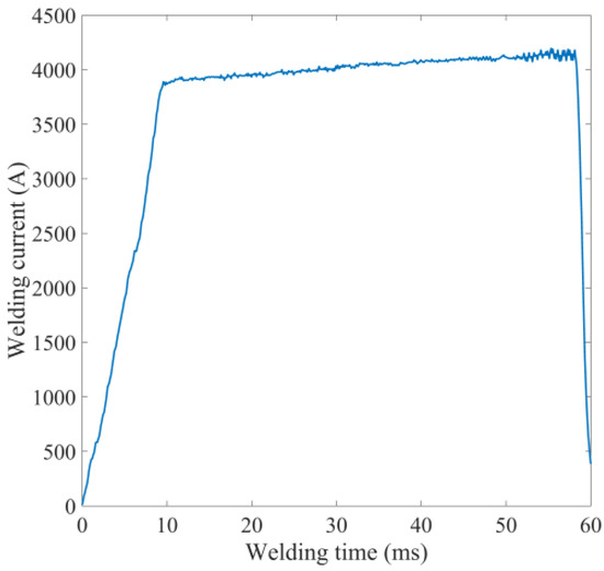
Figure 8.
The measured welding current for the 20th weld.
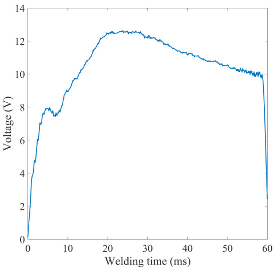
Figure 9.
The measured voltage for the 20th weld.
Figure 10 shows the dynamic resistance signal of the 20th weld. In general, the change in dynamic resistance with welding time can be divided into three stages. First, the welding current gradually increases from a very low value to 4 kA and stabilises at this value. The upper and lower welding plates generate contact resistance affected by electrode pressure. The contact resistance generates heat and causes the contact surface of the welding plate to soften when exposed to the welding current. The contact area of the upper and lower steel plates increases, the contact resistance decreases and the dynamic resistance value decreases until it reaches the α point. After the upper and lower metal plates are in close contact, the temperature of the welded area increases under the effect of resistance heat. As a result, the resistivity of the BH 340 steel plate increases, and when the temperature reaches the melting point of the metal, the metal melts. At this stage, the dynamic resistance increases until it reaches the β point. This point means that the metal in the weld area has melted to a certain extent and the liquid nugget has reached a certain size. Next, the energy dissipated by the electrode exceeds the heat created by the welding current, and the dynamic resistance decreases again until it reaches the end point.
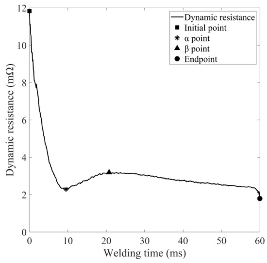
Figure 10.
A typical dynamic resistance signal.
The basic objective of this study is to construct a robust model to quantitatively approximate the true functional relationship between the dynamic resistance signal and the electrode tip diameter in the non-stop resistance spot welding process, focusing on the mapping relationship between the dynamic resistance signal and the electrode tip diameter. Therefore, it is very necessary to first correlate the dynamic resistance curve with the electrode tip diameter. However, a dynamic resistance curve contains hundreds of data, so it is necessary to extract the most important data to achieve dimensionality reduction. Figure 11 shows the evolution of the dynamic resistance signal when repeated at different welding times. This figure clearly shows that the dynamic resistance signal changes regularly as the number of joints increases. The resistance value at the β point gradually decreases, and the welding time to reach this value is delayed accordingly. The overall dynamic resistance curve shows a downward trend as the number of joints increases, which is caused by the increasing electrode tip diameter due to electrode wear and the resulting decrease in welding current density [24]. This finding is consistent with previous research showing that an increase in electrode tip diameter is an indication of electrode wear [5]. When electrode wear is severe, the welding current density will decrease, and the resulting heat will also decrease. At this point, the heating rate of the weld area is slower, and it takes longer to reach the same welding heat as the previous weld point, so the time for the corresponding key points to appear is also delayed. Figure 11 shows the trends as the number of welds increases. As the number of welding times increases from 20 to 144, the resistance value of the β point decreases from 3.57 to 1.84 mΩ, and its appearance time is delayed by 19.56 ms. The same conclusion can be drawn from Ohm’s law: welding heat is in direct proportion to the square of the welding current. If the density of the welding current is lower, it takes longer to reach a given welding heat. Bogaerts et al. [25] discovered that the time to reach the β-point of the dynamic resistance is highly related to the heating rate during welding. It can be realised that the resistance value of the β point is also closely related to the corresponding welding time and the degree of electrode wear.
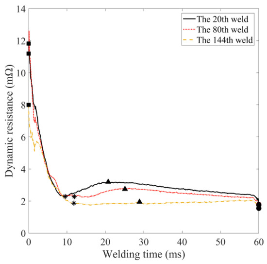
Figure 11.
Dynamic resistance variations with number of welds (Symbols used in this diagram correspond to those in Figure 10).
According to the change in dynamic resistance with the number of welded joints, some features can be extracted from the signal to express its changes. The positions of the α and β points and their resistance values are extracted. The final value of the resistance signal [26] and the integral value of the dynamic resistance [27] are also extracted. The slope between the four key points of the dynamic resistance (start point, α point, β point and end point) is also calculated. Table 4 lists the 10 feature values extracted from the dynamic resistance signal.

Table 4.
Interpretation of the extracted characteristics of the dynamic resistance signal.
3.3. Establishing Models for the Extracted Features
Regression analysis, a quantitative statistical/computational technique, examines the functional relationship between independent variables and dependent variables in order to simulate and approximate the mapping relationship between them to the maximum extent. The regression model is obtained by analysing the relationship between the independent variables and the dependent variables using the method of least squares. Analysis of variance (ANOVA) was used as a tool to determine the significance and robustness of the regression model.
Assuming the independent variables () are continuous, their errors are small enough to be ignored. The functional relationship between the independent variables () and the dependent variable y can be given by the following formula [28]:
The functional relationship between independent and dependent variables requires a more accurate approximation. It is thus necessary to establish a regression equation to simulate the mapping relationship between them. The polynomial regression model is the most commonly used, and its expression can usually be described as follows:
where ε denotes the model error, xi represents each independent variable, and indicates the dependent variable. The regression coefficient ai can be estimated from the obtained experimental data using the least squares regression method.
To investigate how the characteristics extracted from the dynamic resistance signal correlate with electrode size D, Table 5 expresses the correlation coefficient between them. This table clearly shows that the feature k3 has the largest correlation coefficient with the electrode diameter of 0.882, while the feature re of the dynamic resistance has the smallest correlation coefficient value. Features with correlation coefficients less than 0.5 were discarded, and the remaining nine features (, , , , , , , , and ) were used as inputs to the upcoming regression model to predict the electrode tip diameter (D). The regression model was obtained using the stepwise regression analysis method and MATLAB software (MATLAB R2017b.). The basic idea of the stepwise regression analysis method is to automatically select the most important variables from a large number of available variables and build a prediction model for regression analysis. The basic idea is to introduce the independent variables one by one, and the condition for introducing them is that the sum of squares of the partial regression is significant after testing. At the same time, each time a new independent variable is introduced, the old independent variables should be tested one by one, and the independent variables with insignificant partial regression sums of squares should be eliminated. In this way, variables are introduced and eliminated until no new variables are introduced and no old variables are eliminated. The 43 groups of data obtained from the welding experiment and the carbon printing experiment on carbon paper are divided into two groups: training samples and test samples. To obtain the regression model, 33 groups of all data were randomly selected as training samples, and another 10 groups of the test samples were used to verify the simulation accuracy and performance of the model. All regression and ANOVA results were performed on the average values of the two sets of data.

Table 5.
The correlation coefficients between the extracted features and the electrode diameter.
First, the regression model was constructed using the stepwise regression method based on the features extracted from the dynamic resistance signal. In this case, the Matlab software (MATLAB R2017b) constructed different linear models according to the different data randomly selected each time. After many attempts, only the features of and were retained, while other features like were discarded, even though they have high correlation coefficients with the electrode tip diameter.
Table 6 and Table 7 show the ANOVA results of the linear regression model. If the p-value of the model and the terms included in the model are less than 0.1, it indicates that they are significant and should be retained. Otherwise, they should be discarded. Therefore, among the nine features (, , , , , , , , and ) with a correlation coefficient with the electrode tip diameter greater than 0.5, only the extracted features , and are selected. By calculating the coefficient R2, the adjusted R2 and the sum of squared prediction errors, the fit of the regression model can be evaluated. A good regression model should have a coefficient of determination close to 1 and a small sum of squared prediction errors. The R2 coefficient of this model is 0.9000, which implies that 90% of the experimental data agrees with the predicted data. The model only fails to predict the remaining 10% of the data. The adjusted R2 is 0.8897, which is very adjacent to 0.9000 and also close to 1. Among the p-values of all the nine features, only , and have p-values lower than 0.05, so the conclusion that can be drawn that they are highly significant [29] and should be retained in this linear regression model.

Table 6.
The results of the ANOVA for the first model of the linear regression.

Table 7.
Linear regression model ANOVA results for each term.
To obtain a more accurate prediction model, a linear regression model with interaction terms was attempted to approximate the mapping relationship between the characteristic values of the dynamic resistance curve and the electrode diameter. The retained features extracted from the dynamic resistance curve (, , and ) and the interaction terms (, , and ) between them are used as independent variables in the regression model, and the electrode tip diameter D is the dependent variable. The stepwise regression method was used, and Matlab software (MATLAB R2017b) was used to construct a linear regression model with interaction terms. The results of the variance analysis of this model are illustrated in Table 8 and Table 9. This linear regression model is very significant as its p-value is much lower than 0.05. R2 and adjusted R2 are very similar and close to 1, and their values are higher than those of the first linear model. In such a case, the linear regression model with interaction terms is more accurate in predicting the electrode diameter. Figure 12 is a good illustration of this statement. The graph reflects that the residual error of the second model is smaller.

Table 8.
Results of the ANOVA for the linear regression model with interaction terms.

Table 9.
ANOVA results of the linear regression model with interaction terms for each term.
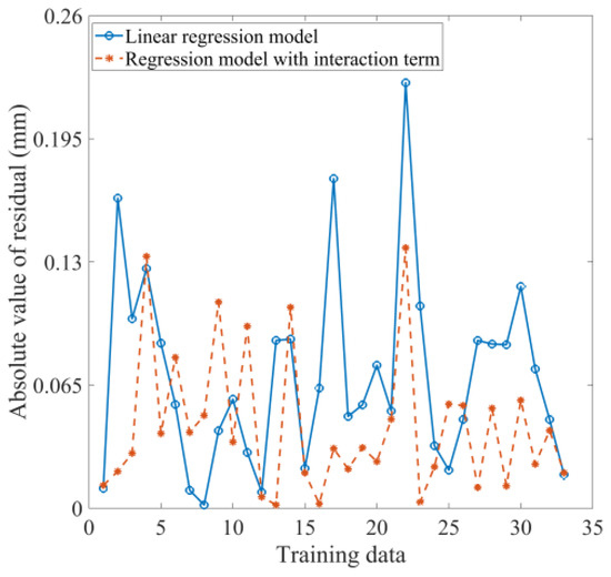
Figure 12.
The residuals of the two models based on the training data.
In accordance with the results of the analysis of variance, the two regression models can be depicted as follows:
where D is the electrode diameter, while r0, P and k3 are the features extracted from the dynamic resistance.
The prediction accuracy of the linear regression model and the linear regression model with interaction terms is shown in Figure 13. This result is obtained using the 10 groups of testing data. The maximum prediction error of the linear regression model with interaction terms is 0.30 mm, while the maximum prediction error of the linear regression model is 0.50 mm. The corresponding relative prediction errors are 7.69% and 12.75%, respectively, as revealed in Table 10. It is not difficult to see that the linear regression model with interaction terms has a more accurate ability to evaluate and predict the electrode tip diameter than the linear regression model. In this circumstance, it is highly recommended to use a linear regression model with interaction terms related to selected features of the dynamic resistance curve to predict the electrode tip diameter. In such a case, monitoring dynamic resistance signals to obtain changes in the electrode diameter can be an effective method of assessing the extent of electrode wear in practical production applications.
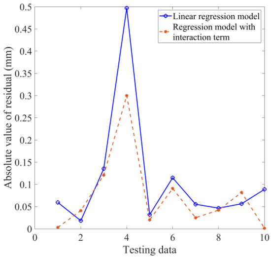
Figure 13.
A comparison of the residuals of the two models.

Table 10.
The statistics of the residuals of the two models.
The subject of this study is closely related to trends in the automotive industry. Therefore, a complete and critical evaluation of the proposed solution in terms of suitability under real welding conditions and some editorial corrections are required. In this case, in order to verify the reliability of the prediction model proposed in this article for predicting the variation of the tip diameter of resistance spot welding electrodes with the number of welding points, it is planned to use a pair of new electrodes and perform continuous welding under the same welding conditions mentioned in Section 2. The same test method is used to obtain the electrode tip diameter. The number of welding times is 54 and the electrode tip diameter is tested every few welds. Figure 14 displays the predicted electrode tip diameter and the measured value using the linear regression model with interaction terms shown in Equation (5). Figure 15 shows the relative error of the model prediction. Table 11 lists the statistical values of the model prediction residuals.
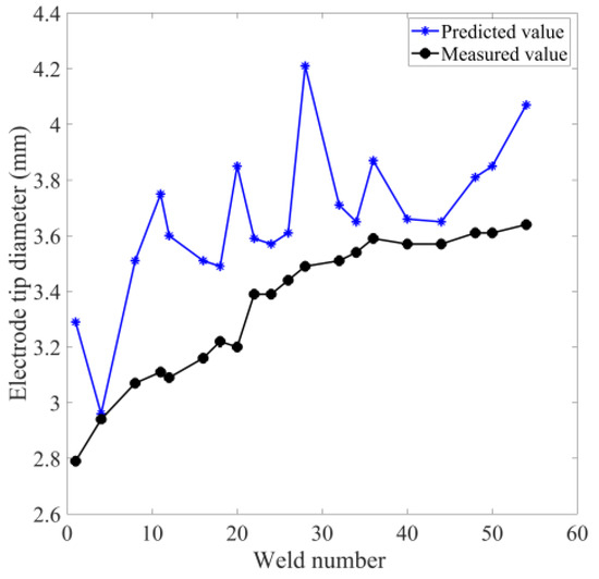
Figure 14.
Prediction of electrode tip diameter versus measured value based on the linear regression model with interaction term when welding with a pair of new electrodes.
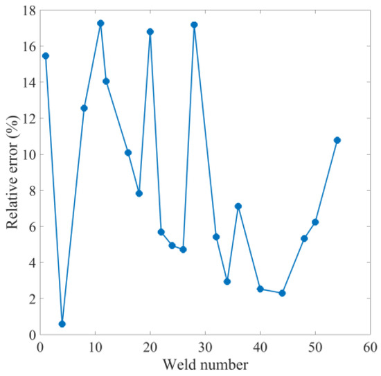
Figure 15.
Relative errors based on the linear regression model with interaction term when welding with a pair of new electrodes.

Table 11.
The statistical values of the residuals based on the linear regression model with interaction terms when welding with a pair of new electrodes.
The results show that, unexpectedly, the predicted values from the model are greater than the measured values. This implies that the model using dynamic resistance to predict electrode wear is more conservative; i.e., when the wear of the spot welding electrode actually reaches the critical point of its life, the model predicts that it has failed and the electrode needs to be replaced or repaired. On the one hand, this is more conservative in terms of ensuring the quality of the joint, but on the other hand, it may result in wasted electrodes. Furthermore, the relative error of the model predictions is within 20%. The maximum absolute error is 0.72 mm. This indicates that the performance of the regression model in the welding situation of completely new electrodes is acceptable but not fabulous.
The linear model with interactions built from the stepwise regression clearly overestimates electrode degradation and appears to be very sensitive to small variations in the dynamic resistance curve. The global tendency of the model follows the overall degradation of the electrode. Some of the possible reasons regarding how to address these and what needs to be accomplished in the future include the following:
(1) As only 33 data sets were used to build the regression model in this article, the optimal regression model might not be obtained due to the limited data size. Therefore, future attempts to expand the data scale and use the average value obtained from multiple measurements to build a regression model are expected to perform better when faced with completely new data. In such a case, the reliability of the model will be improved by constructing a more complete database with several endurance tests and training the stepwise regression model on this database.
(2) The method of manually extracting features from dynamic resistance curves is often based on experience and is highly subjective. The characteristic values selected often vary from person to person, and very important characteristic values may be missed. Dimensionality reduction methods such as principal component analysis [30] and deep learning algorithms [31] can extract feature values according to certain rules, so they are expected to solve this problem.
(3) The functional relationship between the characteristic values extracted from the dynamic resistance signal and the electrode tip diameter may be a very complex non-linear relationship, so simply using a linear regression model with interaction terms is not sufficient to simulate the complex mapping relationship between them. Intelligent algorithms such as artificial neural networks have the ability to approximate any non-linear mapping [32], so the use of this artificial intelligence algorithm is expected to solve this problem.
(4) Some researchers use the better non-linear function approximation capability of artificial neural networks and combine it with the stepwise regression analysis method to predict the observed variables of interest [33]. Therefore, it is possible to obtain more satisfactory results by using the methods based on previous publications and applying them to electrode wear prediction.
In the future work, we will carry out tests on an actual production line to compare the estimated and measured electrode tip diameters over the entire electrode life (i.e., from 0 to XXX welds) to verify the accuracy of the developed new model over the entire electrode life.
4. Conclusions
(1) As the weld number increases, the β point of the dynamic resistance signal appears later, and its value also shows a smaller trend. When the number of welding times increases from 20 to 144, the resistance value of the β point decreases from 3.57 to 1.84 mΩ, and its appearance time is delayed by 19.56 ms.
(2) The characteristic values extracted from the dynamic resistance curve serve as independent variables, while the electrode diameter is the dependent variable. Based on this, a linear regression equation and a linear regression model with interaction terms are established. The analysis of variance results verify that the p values of the linear regression equation and the linear regression model with interaction terms are both less than 0.0001, and their adjusted R2 values are approximately 0.89 and 0.95, respectively.
(3) When the prediction accuracy of the regression model was tested using test data, it was found that the linear regression model with interaction terms performed better in predicting the electrode diameter. Its maximum absolute error is 0.30 mm. The maximum relative error is 7.69%.
(4) The maximum absolute error is 0.72 mm, and the relative error of the model predictions is within 20% based on the linear regression model with interaction terms when welding with a pair of new electrodes. This indicates that the linear regression model with interaction terms is barely satisfactory in monitoring electrode status. Instead of traditional manual feature extraction methods for predicting electrode status, future work may include deep learning methods that process dynamic resistance signals and obtain mapping relationships between dynamic resistance signals and electrode wear.
Author Contributions
D.Z.: Conceptualisation, Methodology, Formal analysis, Writing—original draft, Writing—review and editing, Project administration, Funding acquisition. N.V.: Software, Data curation. M.S.: Supervision, Investigation. S.B.: Software, Validation, Investigation. A.K.: Conceptualisation, Resources, Visualisation. A.G.: Resources, Data curation. All authors have read and agreed to the published version of the manuscript.
Funding
This research is funded by a grant from the Russian Science Foundation with the number 22-29-20095.
Data Availability Statement
Data are contained within the article.
Conflicts of Interest
The authors declare no conflict of interest.
References
- Schmolke, T.; Brunner-Schwer, C.; Biegler, M.; Rethmeier, M.; Meschut, G. On welding of high-strength steels using laser beam welding and resistance spot weld bonding with emphasis on seam leak tightness. J. Manuf. Mater. Process. 2023, 7, 116. [Google Scholar] [CrossRef]
- Palmieri, M.E.; Galetta, F.R.; Tricarico, L. Study of tailored hot stamping process on advanced high-strength steels. J. Manuf. Mater. Process. 2022, 6, 11. [Google Scholar] [CrossRef]
- Khalil, C.; Marya, S.; Racineux, G. Magnetic pulse welding and spot welding with improved coil efficiency—Application for dissimilar welding of automotive metal alloys. J. Manuf. Mater. Process. 2020, 4, 69. [Google Scholar] [CrossRef]
- Zhao, D.; Vdonin, N.; Radionova, L.; Glebov, L.; Guseinov, K. Resistance spot welding of high-strength low-alloyed (HSLA) 420 steel and bake-hardening (BH) 220 steel. Int. J. Adv. Manuf. Technol. 2023, 128, 1441–1453. [Google Scholar] [CrossRef]
- Sifa, A.; Baskoro, A.S.; Supriadi, S.; Endramawan, T.; Badruzzaman, B.; Dionisius, F. Aging and degradation of electrode Cu spot welding. AIP Conf. Proc. 2019, 2187, 040001. [Google Scholar]
- Kim, J.W.; Murugan, S.P.; Kang, N.H.; Park, Y.D. Study on the effect of the localized electrode degradation on weldability during an electrode life test in resistance spot welding of ultra-high strength steel. Korean J. Met. Mater. 2019, 57, 715–725. [Google Scholar] [CrossRef]
- Mahmud, K.; Murugan, S.P.; Cho, Y.; Ji, C.; Nam, D.; Park, Y.D. Geometrical degradation of electrode and liquid metal embrittlement cracking in resistance spot welding. J. Manuf. Process. 2021, 61, 334–348. [Google Scholar] [CrossRef]
- Zhao, D.; Vdonin, N.; Bezgans, Y.; Radionova, L.; Glebov, L. Correlating electrode degradation with weldability of galvanized BH 220 steel during the electrode failure process of resistance spot welding. Crystals 2023, 13, 39. [Google Scholar] [CrossRef]
- Zheng, Z.; Tao, J.; Fang, X.; Xue, H. Life and failure of oriented carbon nanotubes composite electrode for resistance spot welding. Matéria 2023, 28, e20230005. [Google Scholar] [CrossRef]
- Mathiszik, C.; Köberlin, D.; Heilmann, S.; Zschetzsche, J.; Füssel, U. General approach for inline electrode wear monitoring at resistance spot welding. Processes 2021, 9, 685. [Google Scholar] [CrossRef]
- Ibáñez, D.; Garcia, E.; Soret, J.; Martos, J. An unsupervised condition monitoring system for electrode milling problems in the resistance welding process. Sensors 2022, 22, 4311. [Google Scholar] [CrossRef]
- Zhou, L.; Li, T.; Zheng, W.; Zhang, Z.; Lei, Z.; Wu, L.; Zhu, S.; Wang, W. Online monitoring of resistance spot welding electrode wear state based on dynamic resistance. J. Intell. Manuf. 2022, 33, 91–101. [Google Scholar] [CrossRef]
- Panza, L.; Bruno, G.; De Maddis, M.; Lombardi, F.; Spena, P.R.; Traini, E. Data-driven framework for electrode wear prediction in resistance spot welding. In Proceedings of the IFIP International Conference on Product Lifecycle Management, Curitiba, Brazil, 11–14 July 2021; pp. 239–252. [Google Scholar]
- Panza, L.; De Maddis, M.; Spena, P.R. Use of electrode displacement signals for electrode degradation assessment in resistance spot welding. J. Manuf. Process. 2022, 76, 93–105. [Google Scholar] [CrossRef]
- Johnson, N.N.; Madhavadas, V.; Asati, B.; Giri, A.; Hanumant, S.A.; Shajan, N.; Arora, K.S. Multi-objective optimization of resistance spot welding parameters of BH340 steel using Kriging and NSGA-III. Trans. Indian Inst. Met. 2023, 76, 3007–3020. [Google Scholar] [CrossRef]
- Pawar, S.; Singh, A.K.; Park, K.S.; Choi, S.H. Effect of welding current on the microstructural evolution and lap-shear performance of resistance spot-welded 340BH steel. Mater. Charact. 2023, 203, 113126. [Google Scholar] [CrossRef]
- Pawar, S.; Singh, A.K.; Kaushik, L.; Park, K.S.; Shim, J.; Choi, S.H. Characterizing local distribution of microstructural features and its correlation with microhardness in resistance spot welded ultra-low-carbon steel: Experimental and finite element characterization. Mater. Charact. 2022, 194, 112382. [Google Scholar] [CrossRef]
- Kim, S.; Hwang, I.; Kim, D.Y.; Kim, Y.M.; Kang, M.; Yu, J. Weld-quality prediction algorithm based on multiple models using process signals in resistance spot welding. Metals 2021, 11, 1459. [Google Scholar] [CrossRef]
- Butsykin, S.; Gordynets, A.; Kiselev, A.; Slobodyan, M. Evaluation of the reliability of resistance spot welding control via on-line monitoring of dynamic resistance. J. Intell. Manuf. 2023, 34, 3109–3129. [Google Scholar] [CrossRef]
- Kimchi, M.; Phillips, D.H. Resistance Spot Welding: Fundamentals and Applications for the Automotive Industry; Springer Nature: Berlin/Heidelberg, Germany, 2023; pp. 23–26. [Google Scholar]
- Xing, B.; Xiao, Y.; Qin, Q.H.; Cui, H. Quality assessment of resistance spot welding process based on dynamic resistance signal and random forest based. Int. J. Adv. Manuf. Technol. 2018, 94, 327–339. [Google Scholar] [CrossRef]
- Brydak, K.; Szlachta, A. Measuring methods of welding process parameters. Meas. Autom. Monit. 2016, 62, 26–28. [Google Scholar]
- Podržaj, P.; Polajnar, I.; Diaci, J.; Kariž, Z. Overview of resistance spot welding control. Sci. Technol. Weld. Join. 2008, 13, 215–224. [Google Scholar] [CrossRef]
- Seo, J.C.; Choi, I.D.; Son, H.R.; Ji, C.; Kim, C.; Suh, S.B.; Seo, J.; Park, Y.D. A comparative study of constant current control and adaptive control on electrode life time for resistance spot welding of galvanized steels. J. Weld. Join. 2015, 33, 47–55. [Google Scholar] [CrossRef]
- Bogaerts, L.; Dejans, A.; Faes, M.G.; Moens, D. A machine learning approach for efficient and robust resistance spot welding monitoring. Weld. World 2023, 67, 1923–1935. [Google Scholar] [CrossRef]
- Wen, J.; Jia, H. Real-time monitoring system for resistance spot welding quality. Eng. Res. Express 2023, 5, 015006. [Google Scholar] [CrossRef]
- Chen, G.; Sheng, B.; Luo, R.; Jia, P. A parallel strategy for predicting the quality of welded joints in automotive bodies based on machine learning. J. Manuf. Syst. 2022, 62, 636–649. [Google Scholar] [CrossRef]
- Xing, L.; Yu, T.; Zhang, J.; Xing, X.; Lu, H. Optimization and improvement of the projection welding of nut based on regression analysis. ISIJ Int. 2023, 63, 694–702. [Google Scholar] [CrossRef]
- Anandan, B.; Manikandan, M. Machine learning approach with various regression models for predicting the ultimate tensile strength of the friction stir welded AA 2050-T8 joints by the K-Fold cross-validation method. Mater. Today Commun. 2023, 34, 105286. [Google Scholar] [CrossRef]
- Zhao, D.; Bezgans, Y.; Wang, Y.; Du, W.; Lodkov, D. Performances of dimension reduction techniques for welding quality prediction based on the dynamic resistance signal. J. Manuf. Process. 2020, 58, 335–343. [Google Scholar] [CrossRef]
- Nogales, R.E.; Benalcázar, M.E. Hand gesture recognition using automatic feature extraction and deep learning algorithms with memory. Big Data Cogn. Comput. 2023, 7, 102. [Google Scholar] [CrossRef]
- Cebollada, S.; Payá, L.; Flores, M.; Peidró, A.; Reinoso, O. A state-of-the-art review on mobile robotics tasks using artificial intelligence and visual data. Expert Syst. Appl. 2021, 167, 114195. [Google Scholar] [CrossRef]
- Liu, B.; Zhao, Q.; Jin, Y.; Shen, J.; Li, C. Application of combined model of stepwise regression analysis and artificial neural network in data calibration of miniature air quality detector. Sci. Rep. 2021, 11, 3247. [Google Scholar] [CrossRef] [PubMed]
Disclaimer/Publisher’s Note: The statements, opinions and data contained in all publications are solely those of the individual author(s) and contributor(s) and not of MDPI and/or the editor(s). MDPI and/or the editor(s) disclaim responsibility for any injury to people or property resulting from any ideas, methods, instructions or products referred to in the content. |
© 2023 by the authors. Licensee MDPI, Basel, Switzerland. This article is an open access article distributed under the terms and conditions of the Creative Commons Attribution (CC BY) license (https://creativecommons.org/licenses/by/4.0/).