Article

Comprehensive Investigation of Hastelloy C-22 Powder Weld Overlay on SA 240 Type 316L Using Laser Beam Welding for Enhanced Performance

by
Manish V. Mehta
1,2,
Mrunalkumar D. Chaudhari
3,*,
Rakesh Chaudhari
4,
Sakshum Khanna
4 and
Jaykumar Vora
4,*
1
Research Scholar, Gujarat Technological University, Ahmedabad 382424, India
2
Government Polytechnic, Rajkot 360003, India
3
L. D. College of Engineering, Ahmedabad 380015, India
4
School of Technology, Pandit Deendayal Energy University, Gandhinagar 382007, India
*
Authors to whom correspondence should be addressed.
J. Manuf. Mater. Process. 2023, 7(6), 207; https://doi.org/10.3390/jmmp7060207
Submission received: 27 October 2023 / Revised: 21 November 2023 / Accepted: 23 November 2023 / Published: 24 November 2023

Abstract

:
This article presents a comprehensive study on the application of Hastelloy C-22 powder weld overlay on SA 240 Type 316L austenitic stainless steel using the laser beam welding process. This novel combination of materials and processes was investigated for the first time, focusing on its potential utility for various industrial applications. Various testing techniques, including visual testing, hardness testing, bend testing, chemical composition analysis using optical spectroscopy, corrosion resistance assessment through the potentiodynamic polarization technique, and macro- and microstructural observation, were employed to evaluate the performance of the weld overlay. The research findings had several significant outcomes. Notably, precise control and minimal alloy mixing were achieved, as evidenced by the dilution at a remarkable height of 0.5 mm from the base metal. The laser welding process resulted in a minimal heat-affected zone and a fine columnar interdendritic microstructure, with average primary and secondary arm spacing values of 3.981 µm and 2.289 µm, respectively. Rigorous visual and bend testing confirmed the integrity of the sound welds in the overlay. Moreover, the high-quality finish of the weld overlay eliminated the need for extensive machining and finishing processes, resulting in cost reductions. This study also demonstrated primary and secondary inter-laminar spacing, leading to improved overall structural integrity. Additionally, the weld overlay exhibited excellent hardness characteristics. The current work contributes to the advancement of welding processes and provides practical solutions to enhance efficiency, cost-effectiveness, and structural performance in relevant industrial applications.

1. Introduction

The petrochemical, oil and gas, pharmaceutical, and chemical processing industries play a crucial role in the global economy by providing a wide range of chemical products and materials used in various sectors such as energy, manufacturing, and transportation. Corrosive surface degradation of equipment is a significant challenge faced by the oil and natural gas industries. This problem arises primarily due to the presence of corrosive and/or abrasive substances that contaminate the distillation and processing lines involved in the handling of petroleum, petroleum derivatives, and natural gas [1,2]. The degradation can occur through individual or combined actions of erosion, corrosion, and/or friction, and it is influenced by factors such as temperature, chemical composition, and strength properties of the exposed surface material [3,4]. To mitigate this issue, employing protective coating layers made of specialized corrosion-resistant materials is an effective preventive measure that helps minimize structural degradation of equipment and components [5,6,7]. With increasing demands for corrosion-resistant materials in various applications, there is a constant need for innovative solutions that can improve material performance, cost efficiency, and reliability [8,9]. The industries operate in highly corrosive environments containing aggressive chemicals, high temperatures, and mechanical stresses. Corrosion poses a significant threat to the structural integrity and longevity of equipment and components used in petrochemical plants. Therefore, the selection of suitable materials and protective measures is crucial to ensure reliable and safe operations [10]. Weld overlay techniques have gained significant attention as effective methods for improving the corrosion resistance and mechanical properties of base materials [11,12].
Corrosion resistance weld overlay techniques are of utmost importance in protecting critical equipment and structures from the damaging effects of corrosive environments. These techniques involve applying a layer of corrosion-resistant material through welding onto the surface of a base metal. The significance of a corrosion resistance weld overlay lies in its ability to create a protective barrier that shields the base metal from corrosive media, such as acids, chemicals, and seawater. By effectively preventing corrosion, this technique also extends the lifespan of equipment, reducing the need for frequent replacements and maintenance. Additionally, a weld overlay offers a cost-effective solution as it allows targeted protection in vulnerable areas rather than using expensive alloys throughout the entire structure [13]. Overall, a weld overlay plays a crucial role in enhancing the performance, durability, and cost-effectiveness of essential equipment and infrastructure [14,15]. The weld overlay process is utilized to enhance various surface characteristics of the base metal. This involves applying a superior material through an efficient welding technique. Ensuring a high-quality weld overlay is extremely important and is assessed based on several geometric factors such as weld bead height, width, reinforcement, penetration, and overlap. These factors are critical for examining the extent of dilution, which refers to the degree of base metal blending with the filler metal in weld overlay [16,17]. In simpler terms, dilution represents how much the base metal combines with the filler metal in the weld overlay [18,19]. Controlling dilution is a crucial aspect of a weld overlay. Dilution occurs when elements from the base metal mix with the alloy present, thereby diminishing its corrosion-resistant properties. While multiple weld overlay passes can help reduce dilution, this approach results in increased manufacturing costs and changes in the microstructure. Hence, an alternative method to manage dilution is by controlling welding techniques and parameters. Precise control of welding techniques, such as implementing stringer bead weld overlay and managing the overlap of the weld bead, can regulate dilution. Additionally, selecting appropriate welding parameters that target a lower heat input to the base metal enables dilution control without compromising bonding strength. Another effective way to control dilution is by using welding processes with shallow penetration depths [20].
The use of overlay welding techniques has gained significant attention as a viable method for enhancing the surface properties of base materials. By depositing a layer of corrosion-resistant material onto a substrate, overlay welding provides an effective solution to protect critical components from harsh operating conditions, including corrosive environments, high temperatures, and mechanical stresses. Among the various overlay materials available, Hastelloy C-22 is a high-performance nickel–chromium–molybdenum–tungsten alloy [21]. This alloy is especially known for its excellent resistance to a wide range of corrosive environments, including oxidizing and reducing acids [22]. It is particularly well-suited for applications involving harsh chemical processing industries, such as chemical plants, petrochemical facilities, and pharmaceutical plants [23,24]. The significance of the Hastelloy C-22 weld overlay lies in its ability to provide enhanced corrosion resistance to the base metal. The weld overlay creates a protective barrier that shields the base metal from corrosive media, such as acids, alkalis, and chlorides. This is particularly beneficial in environments where the base metal alone may be susceptible to corrosion or attack. However, while the Hastelloy C-22 weld overlay offers numerous benefits, some challenges and difficulties can be encountered during the process [25]. Hastelloy C-22 has different metallurgical properties compared to common base metals like carbon steel or stainless steel, making it challenging to achieve a sound and defect-free weld between the base metal and Hastelloy C-22 overlay [26,27,28]. This is due to the differences in thermal expansion coefficients and melting points [29]. Special care must be taken to ensure the selection of welding parameters, selection of welding consumables, and appropriate welding techniques [30]. Hastelloy C-22 is also prone to solidification cracking and hot cracking during welding, especially when improper welding techniques, such as high heat input or inadequate cleaning, are employed. Mitigating the risk of weld cracking involves using appropriate filler metals, controlling heat input, and ensuring proper cleaning and interpass temperature control [31,32].
The selection of a welding process for a weld overlay is an important decision influenced by various factors. However, the primary considerations include achieving a high-quality finish, minimizing dilution, and maximizing the deposition rate. Commonly used conventional welding processes for filling strip back weld overlay and grinding/chipping the bottom side area include SAW, GTAW, SMAW, and MIG/MAG [33]. Among these, SMAW is frequently utilized in small-scale and medium-scale industries. Each process has its advantages and disadvantages. For example, SMAW and manual GTAW processes have lower deposition rates, whereas MIG/MAG processes may result in more spatter, lower-quality finishes, and higher dilution. SAW, on the other hand, has high heat input and deeper penetration. Advanced welding processes like CMT, HWT, laser cladding, and PTAW offer better control over dilution, higher deposition rates, and improved weld overlay finishes. However, these processes come with higher equipment costs and require skilled manpower. According to the existing literature, PTAW and LBW serve as highly viable alternatives to other surface welding processes. Coatings applied through PTAW and LBW exhibit exceptional quality, competitive wear resistance, and remarkable stability of properties even at high temperatures. Among these welding techniques, PTAW and LBW stand out as an advanced approach that offers numerous advantages compared to traditional methods [34,35,36]. LBW employs a high-intensity laser beam to deliver localized heating, resulting in a focused, well-defined weld zone. This targeted energy input enables precise control over the welding process, minimizing the impact on the surrounding areas and reducing the risk of distortion or harm to the base material. LBW also boasts high welding speeds, improved productivity, and the capability to join dissimilar materials, making it well-suited for diverse industrial applications. The utilization of LBW for a weld overlay presents several advantages compared to conventional welding processes. Firstly, LBW enables precise control over the dilution between the overlay and the base metal, ensuring limited dilution and preserving the desired properties of the overlay material. This feature is particularly important in maintaining the corrosion resistance and mechanical strength of the weld overlay. Secondly, LBW provides excellent process control, reducing the occurrence of weld defects such as cracks, porosity, and incomplete fusion. These defects can compromise the integrity and performance of the weld overlay, making LBW a favorable choice for critical applications. Thirdly, LBW offers improved welding cleanliness by minimizing the introduction of contaminants during the welding process, resulting in high-quality welds with reduced susceptibility to corrosion and other degradation mechanisms. Due to all the above benefits, the LBW process has less dilution compared to PTAW. Given these advantages, there is comparatively little research available using the LBW process. As such, the LBW process for cladding is a new area to study for industry [37,38]. In recent years, there has been a growing trend towards the application of Hastelloy C-22 weld overlay on SA 240 Type 316L in various industries, including petrochemicals. Due to the greater heat resistance properties of stainless steels, they are largely preferred in chemical, oil, gas, and petrochemical sectors [39,40]. This trend is driven by the need for materials that can withstand highly corrosive environments, maintain structural integrity, and reduce maintenance costs [41]. The findings of the current study contribute to the existing knowledge base and provide valuable insights into the successful application of the Hastelloy C-22 powder weld overlay on SA 240 Type 316L in the petrochemical, oil and gas, pharmaceutical, and chemical processing industries.
In summary, the present study investigates the application of the Hastelloy C-22 powder weld overlay on SA 240 Type 316L using the laser beam welding process. The study employs various testing techniques, including visual testing, hardness testing, bend testing, chemical composition analysis using optical spectroscopy, corrosion resistance assessment through the potentiodynamic polarization technique, and macro- and microstructural observation.

2. Experimental Process

In the present study, the deposition of Hastelloy C-22 powder onto austenitic stainless steel SA 240 Type 316 L was experimentally conducted using the laser beam welding process. The aim was to investigate the suitability of the process and material in the current industrial scenario. The experimental setup employed in the present study is illustrated in Figure 1. The setup includes a diode laser power source (Laser Line VG 64 LDF 8000-100), along with a drum powder feeder, shielding and carrier gas setup, and a welding robot.

2.1. Material

The Hastelloy C-22 alloy powder was used to modify the surface of SA 240 Type 316L austenitic stainless steel material via the LBW process. The nominal composition of the Hastelloy C-22 alloy powder and SA 240 Type 316L austenitic stainless steel is presented in Table 1.
The base material used for the present study was 10 mm thick SA 240 Type 316L austenitic stainless steel with the chemical composition shown in Table 1. SA 240 Type 316L austenitic stainless steel plates were cut and machined to size 500 mm × 300 mm × 10 mm. The laser beam welding powder size was assessed using a DSX-1000 microscope, indicating the size range of 33.96 to 105.6 μm.

2.2. Method

In a present research study, the laser beam welding process was used to perform a Hastelloy C-22 alloy powder weld overlay on SA 240 Type 316L, aiming to harness the numerous advantages of the process. Welding of isolated passes was carried out on a bead on a plate with five repetitions, to assess the operational behavior of the process, and the effect of the welding energy on the geometric characteristics (reinforcement and reinforcement/width ratio) and dilution. The best operating parameter was selected on the basis of dilution and visual testing carried out on the bead on a plate. Selected welding parameters were used on welding samples, as shown in Figure 2.
Process parameters must ensure melting and good adhesion even in the vertex, while avoiding high dilution and cracks or flaws due to excessive cooling rates. Two layers of Hastelloy C-22 alloy powder weld overlay were administered on an SA 240 Type 316L base plate through the laser beam welding process. In each layer, the welding of 7 beads was conducted. The process parameters were selected on the basis of results of preliminary trials and the literature [42,43]. Process parameters like the welding power, travel speed, laser spot size, types of welding, carrier gas, and shielding gas used for this welding are summarized in Table 2.
Prior to the welding, the substrate’s top surface was cleaned using ethyl alcohol to remove grease and residue. The initial thickness of the substrate and deposition layer after welding was approximately 15 mm with the deposition of 2 layers of Hastelloy C-22 alloy weld overlay, as shown in Figure 1. After the LBW process, visual examination revealed smooth and regular welds without evident faults, and non-destructive inspection was used to assess the acceptability of the coatings in terms of the absence of cracks, discontinuity areas, and interface defects.

2.2.1. Bend Test

Bend tests provide valuable information about the ductility, integrity, and quality of Hastelloy weld overlays. They ensure that the weld can withstand bending without failure, detect any defects or cracks, and ensure compliance with industry standards and specifications [44]. To characterize the reliability of the welded cladding, i.e., the cladded layers, two specimens were subjected to a set of side edge bend tests. The procedure was carried out according to BS EN ISO 5173:2010/A1:2011. A comprehensive series of bend tests were performed on Hastelloy C-22 weld overlay on SA 240 Type 316L material using the laser beam welding process to measure the weldability, ductility, integrity, and quality of the cladding layers. The bend test results meet the acceptance criteria specified in BS EN ISO 15614-7:2019. A Digital Universal Testing (uniaxial) Machine (FIE UTE-60) was used for the bend tests of these specimens.

2.2.2. Hardness Test

Hardness testing is commonly performed on Hastelloy C-22 weld overlays to evaluate the mechanical properties and integrity of the welded joint. Hardness testing on Hastelloy C-22 weld overlays provides important insights into material quality, weld integrity, heat-affected zone characterization, compliance with acceptance criteria, and quality control. It helps assess the mechanical properties and ensures that the weld overlay meets the required specifications for the intended application [45]. Hardness measurements were performed on transverse cross-sections of the welded specimens using a Vickers hardness tester (Leco, M-400A). Hardness measurements were obtained at the weld area, heat-affected zone, and base metal under a load of 1000 gf. The test method used for hardness testing was EN ISO 9015-1:2011. The location of hardness testing was as shown in Figure 3.

2.2.3. Macro- and Microstructure Examination

Macro examination of Hastelloy C-22 weld overlays on SA240 Type 316L is important for assessing overall weld quality, detecting defects, and ensuring proper fusion and penetration. It helps verify the integrity and reliability of the weld overlay, contributing to the overall performance and longevity of the welded joint. The Hastelloy C-22 cladded AISI 316L plates of dimensions 500 × 300 × 10 mm were drawn into cross-section cuts of 10mm length, 300 mm width, and 10 mm thickness for macro examination. Specimens were polished with SiC sandpapers of grades 120, 320, 400, and 600 followed by alumina powder polishing, and then we etched the samples with Kallins Reagent. The samples were observed at 10× with a stereo zoom microscope (Metlab, The MathWorks, Natick, MA, USA).
The microstructure of a material directly influences its mechanical properties such as strength, hardness, and ductility as well as corrosion properties; by studying the microstructure, one can identify the grain structure, presence of phases, and any potential defects or precipitates that may affect the material’s mechanical behavior. The microstructure study also provides insights into the alloy’s grain boundaries, phase distribution, and the presence of alloying elements that contribute to its corrosion resistance property. For the study of the Hastelloy weld overlay microstructure, the sample was cut in 10 × 300 × 10 mm and was drawn into 20 × 10 × 10 mm using a high-precision micro wire EDM machine. The specimens were polished using SiC sandpapers of grades 120, 320, 400, 600, 800, 1000, and 1200 followed by alumina powder polishing and then diamond paste polishing of 1 μ surface finish. The microstructures of the weld overlay, heat-affected zone, and base metal regions were observed through an optical microscope (Metlab).
The Hastelloy C-22 weld overlay on SA 240 Type 316L with the LBW process was studied for primary and secondary dendritic spacing, as calculated in high resolution using the Olympus DSX-1000 digital microscope (Olympus Corporation, Tokyo, Japan).

2.2.4. Corrosion Resistance Using Potentiodynamic Polarization Technique

The potentiodynamic polarization technique is an electrochemical method used to assess the corrosion resistance of materials, including Hastelloy C-22. Using the potentiodynamic polarization technique, researchers can gain valuable insights into the corrosion resistance of Hastelloy C-22, facilitate material selection, optimize operating conditions, and enhance the overall performance and longevity of the material in corrosive environments. The corrosion behavior of the clad samples of sizes 10 mm (L) × 10 mm (W) surface was investigated by using the potentiodynamic polarization test in ferric sulfate and sulfuric acid solution. The Grammy Interface 1010E (Gamry Instruments, Philadelphia, PA, USA) potentiostat was used to conduct the corrosion analysis.

2.2.5. Chemical Composition Test

The chemical composition study of a weld overlay sample using optical spectroscopy allows for the assurance of the quality, consistency, and compatibility of the weld overlay material. This leads to reliable and long-lasting performance when exposed to various corrosive media. The chemical composition and elemental constituents of the different specimens were examined using optical spectroscopy (Hitachi Foundry Master Pro-2, Hitachi High-Tech Analytical Science, Oxford, UK). The chemical composition was examined at the base metal and at thicknesses of 0.25 mm, 0.5 mm, and 1 mm from the base metal. The testing method employed for this study was ASTM E-3047-16.

3. Results

3.1. Visual Analysis

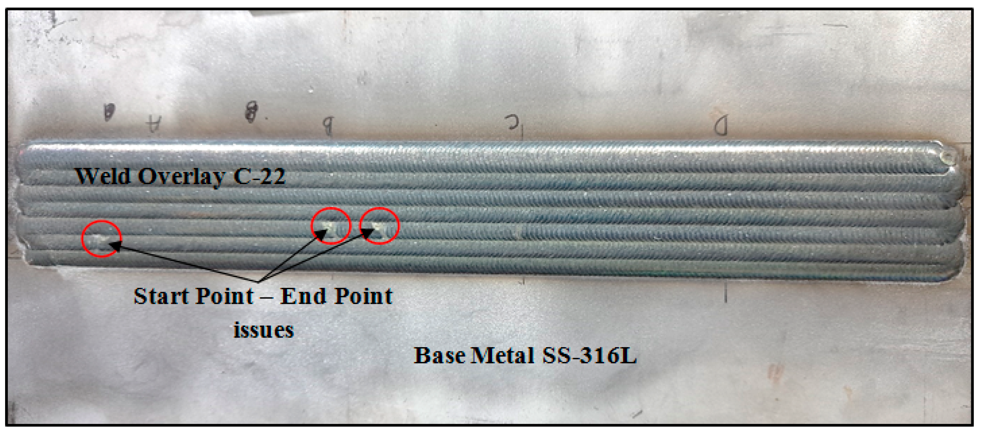
The austenitic stainless steel 316L and Hastelloy weld overlay were visually inspected, and the results indicated a clean surface without any welding flaws. No indications of spatter, undercut, porosity, lack of fusion, inclusion, or cracks were found. This assessment aligns with the expectations we gained from reviewing the literature regarding Hastelloy’s good weldability [46]. Figure 4 illustrates the upper surface of the Hastelloy C-22 weld overlay created by ERNiCrMo-10 on the SS-316L substrate. The image shows issues at the starting and ending points of the automated welding process, which can be attributed to setup problems in operational parameters, such as the calculation of the total welding length. The Hastelloy weld overlay is devoid of welding defects, including spatter, undercut, porosity, lack of fusion, inclusion, cracks, or any other welding flaws.
Figure 4 is representative of the quality of the overlays in the welding conditions used in this work. The high quality of the overlay in Figure 4 is related to the welding parameter selection. The important factors are laser stability and proper lateral overlap of the passes. Due to the planar geometric regularity over the coated area, the absence of flaws, and the low occurrence of splashes, the surface quality is thus deemed adequate.

3.2. Macrostructure Examination

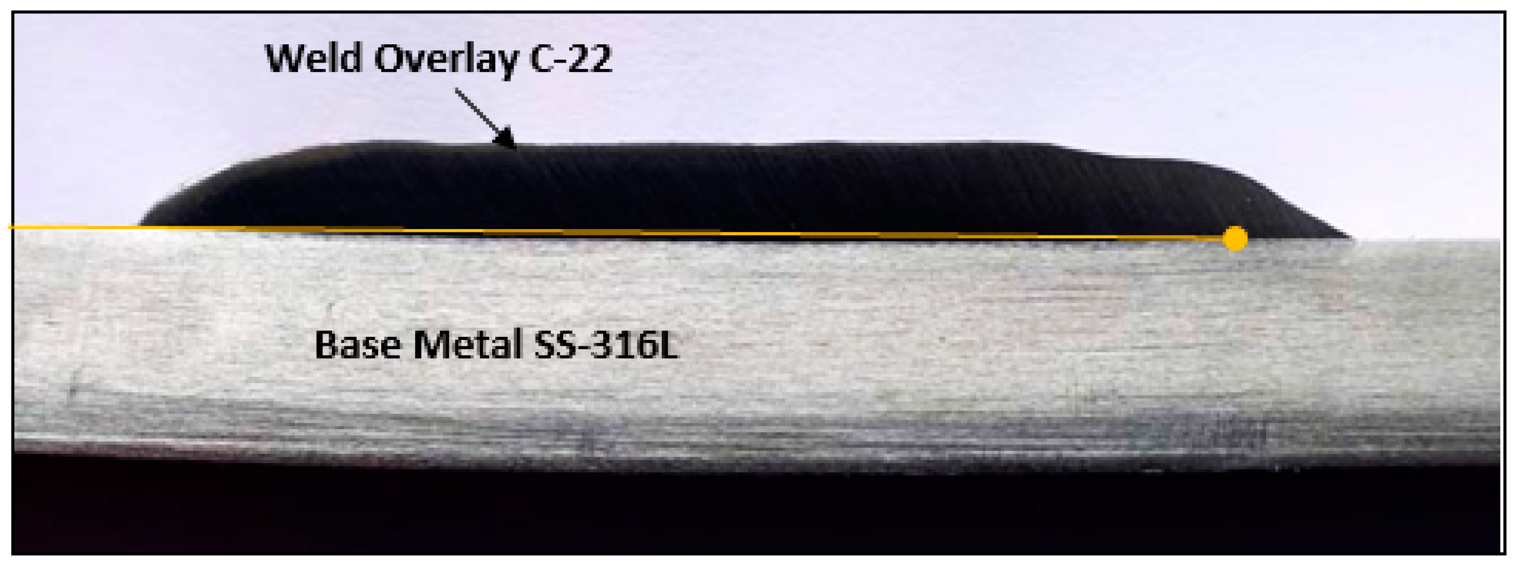
The material underwent a macroscopic examination using 10× magnification, as depicted in Figure 5. The sample was macro-etched, visually observed, and then magnified 10 times under a microscope. This allowed for the examination of the cross-section of the Hastelloy C-22 weld overlay on austenitic stainless steel 316L. Figure 5 displays a cross-section view of the weld overlay and the base metal, revealing no signs of welding defects. Furthermore, the cross-section view illustrates a very low penetration of the Hastelloy weld overlay into the base metal, which can be attributed to the heat input associated with the laser beam welding process [47]. The line in the figure indicates the extent of penetration of the weld overlay metal into the base metal.

3.3. Bend Test Analysis

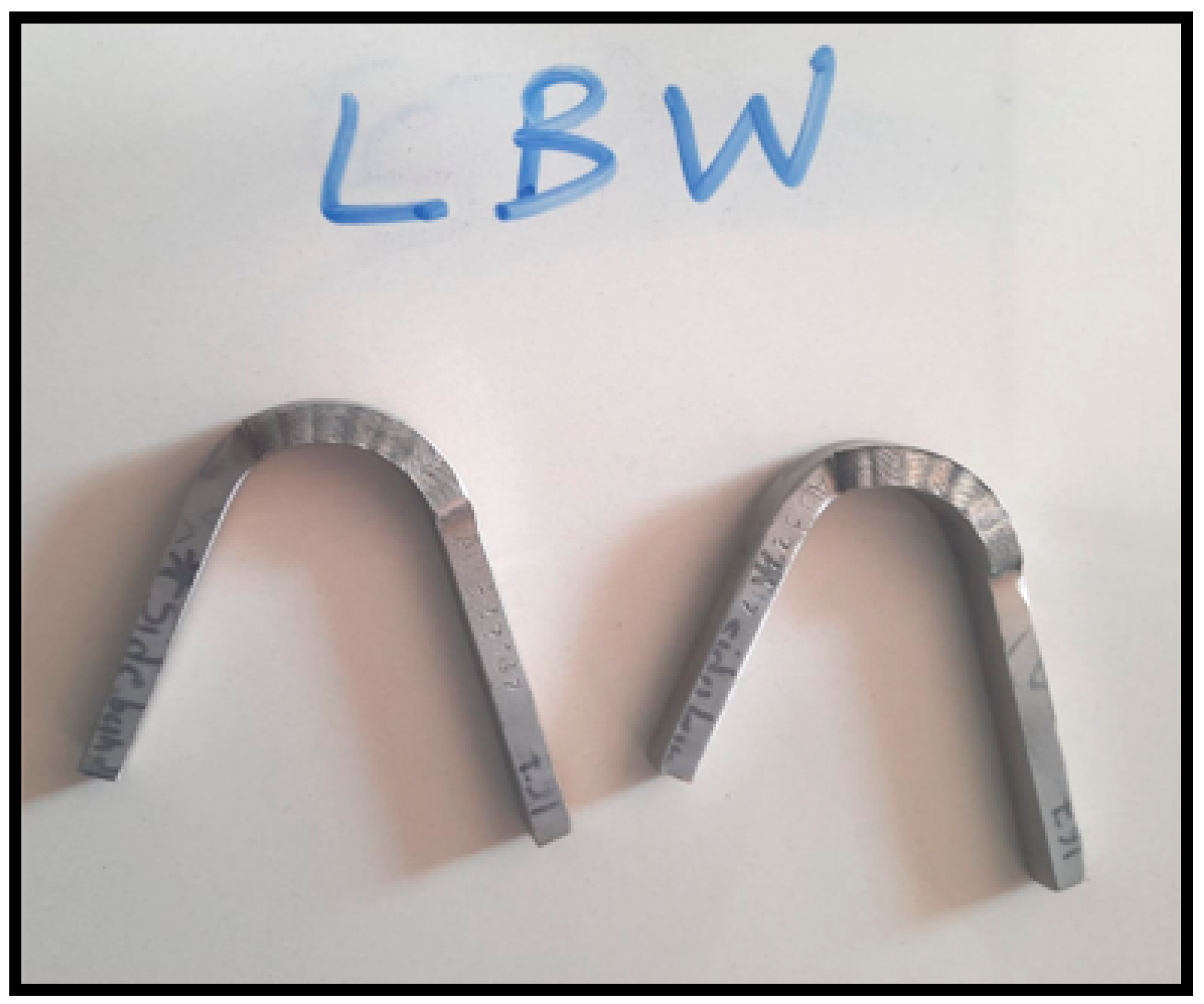
To evaluate the reliability or weldability of the procedure, we applied the optimal parameters determined from the previous tests to actual samples of weld cladding. Specifically, in this research, for better production cost reduction, we used AISI 316 L SS cladding with two layers of Hastelloy C-22. Our main objective was to determine if these parameters would result in welds that were free from issues like holes or cracks commonly encountered in weld cladding. Additionally, we examined for any signs of excessive hardening in the cladding layer or inadequate integration between the cladding layer and the AISI 316 L SS substrate. According to AWS guidelines, defects larger than 3 mm (such as holes or cracks) should not be present, regardless of the orientation, even if the specimen prepared for bending is on the surface/side. Figure 6 shows that no cracks appeared anywhere on the specimen during the two instances of the side bend test using universal testing equipment. These results provide evidence that the parameters used for this research in weld cladding conditions were indeed optimal.

3.4. Hardness Testing

The Vickers hardness profile of the thick coating’s cross-section is presented in Figure 7. The observations are as follows:
(1) The hardness of the base metal, which is significantly lower than that of the weld overlay and heat-affected zone (HAZ), remains relatively constant at around 204 Hv.
(2) The hardness of the weld overlay is approximately 271 Hv. This increase in hardness can be attributed to the development of the microstructure during the weld overlay process. It is well-known that the microstructure and Vickers hardness are closely related, and a finer microstructure often results in greater hardness when the phase composition is the same [48,49].
(3) Both the HAZ hardness and the interface exhibit a similar hardness value of around 266 Hv. There is a relatively small increase in hardness from the HAZ to the coating.
The Vickers hardness profile of the cross-section of the Hastelloy C-22 weld overlay on SS-316L indicates that the hardness of the base metal remains relatively consistent at around 203 Hv. This value is lower compared to the hardness values of the coating and heat-affected zone (HAZ), which are 271 Hv and 266 Hv, respectively. Changes in the solidified morphology of the cladding layers can be attributed to the dilution effect and may have a direct impact on the hardness of the cladding weld. The heat input of the welding process is one of the major influencing parameters responsible for morphological changes in the weld overlay when the same combination of weld overlay and substrate is used. Therefore, we can directly say that the heat input of the process plays an important role in the changes in hardness, dilution, and width of the heat-affected zone. The LBW process involves minimal heat input, as indicated by the research paper, and our ongoing research confirms this finding. The morphology of the microstructure, affected by the heat input, directly influences the metal’s hardness. Additionally, research suggests that a significant reduction in the size of primary dendrites generally leads to an increase in Vickers hardness. In the current scenario, the average hardness of the weld overlay is slightly greater than the maximum hardness (100 HRB, 248 Hv) stated in the ASME code. This greater hardness is attributed to the laminar separation caused by the rapid cooling rate and low-intensity input. In this specific case, the LBW (laser beam welding) technique demonstrates a very low heat input, resulting in a very fine HAZ and weld interface, which cannot be identified separately in Vickers hardness tests or in microstructure studies. In sum, the hardness values at the HAZ and weld overlay are nearly identical.

3.5. Chemical Composition

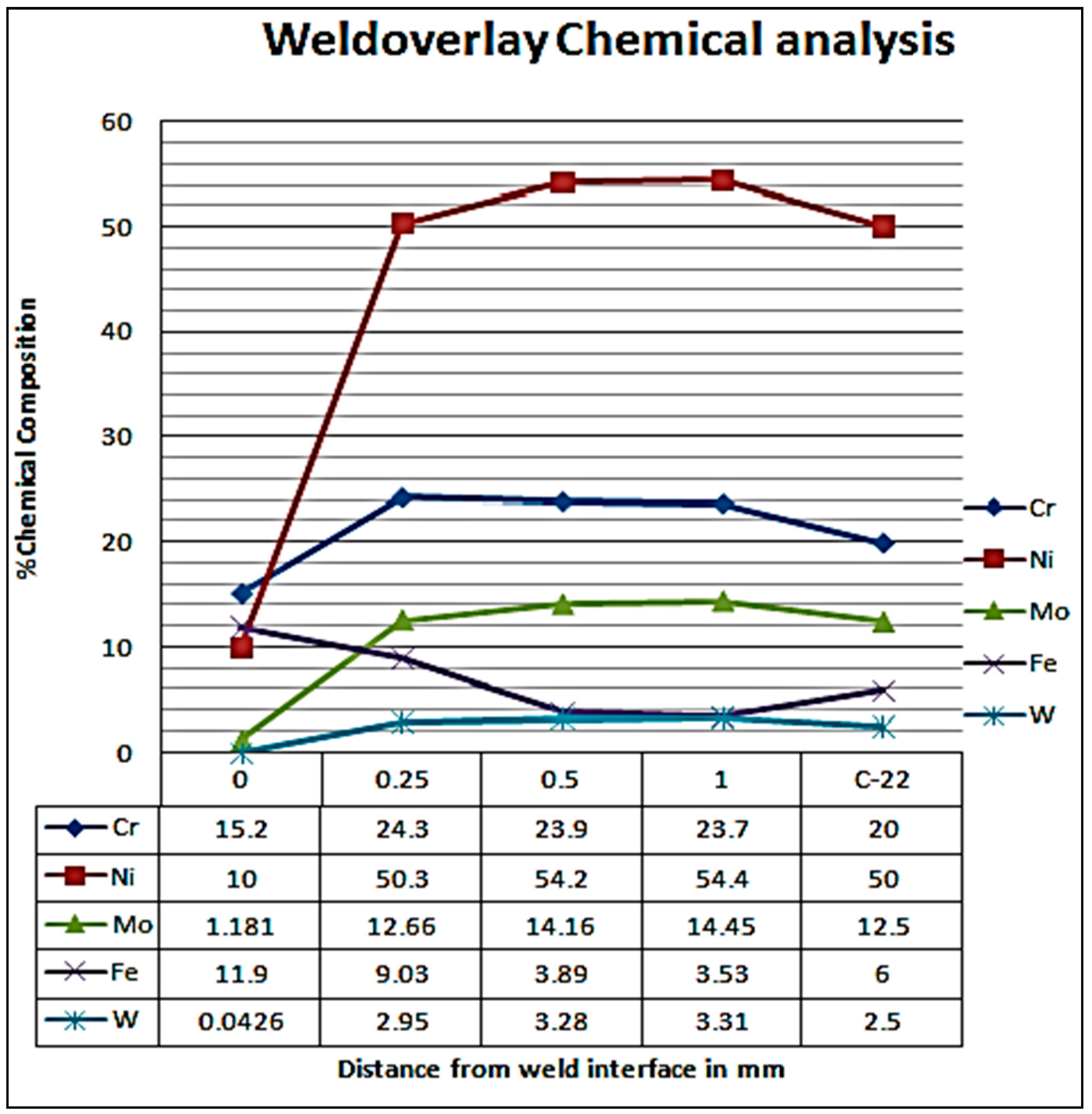
As previously mentioned, the cladding process in this case leads to dilution between the AISI 316L SS substrate and the Hastelloy-22 cladding layers. In Figure 8, the horizontal axis represents the distance in mm from the interface, with the chemical composition of Hastelloy C-22 displayed at the end of the axis. The vertical axis indicates the percentages of chemical composition. The graph indicates that the chemical composition of C-22 closely matches the desired composition from a height of 0.25 mm from the interface, except for the Fe content, which does not meet the requirements. However, from a height of 0.5 mm onwards, the chemical composition aligns with the C-22 chemistry. The accompanying table in Figure 8 illustrates the results of optical spectrometry analysis, which is extensively used in the manufacturing industry to examine chemical composition. It shows a graphical representation of the chemical composition gradients within the AISI 316L SS substrate and the two Hastelloy C-22 cladding layers, highlighting the distribution of major alloying elements such as Ni, Cr, Mo, W, and Fe. It depicts the elemental variations from the weld layer interface to the top surface. Notably, the most significant changes in composition gradient occur at the interface between the substrate and the first cladding layer. In the region where the weld overlay is present, Hastelloy C-22 chemistry is attained starting from a distance of 0.5 mm and onwards. Beyond this point, the composition profiles in the weld overlay regions exhibit similarity.

3.6. Microstructural Analysis

The microstructures of the 316L SS substrate and the two Hastelloy C-22 cladding layers were studied. High-magnification optical microscope images were used to construct a composite image of the Hastelloy weld overlay on the 316L SS sample, as shown in Figure 9. These micrographs closely resemble macro images. The stitched image reveals the presence of porosity, lack of fusion, and a defect-free weld overlay of Hastelloy C-22 on the 316L SS substrate achieved through laser beam welding. The cross-sectional micrographs demonstrate that the microstructure of the SS 316L substrate remains unchanged after the overlay. The laser beam welding process, characterized by low heat input, resulted in no observable heat-affected zone, as indicated by the cross-sectional optical microstructure analysis.
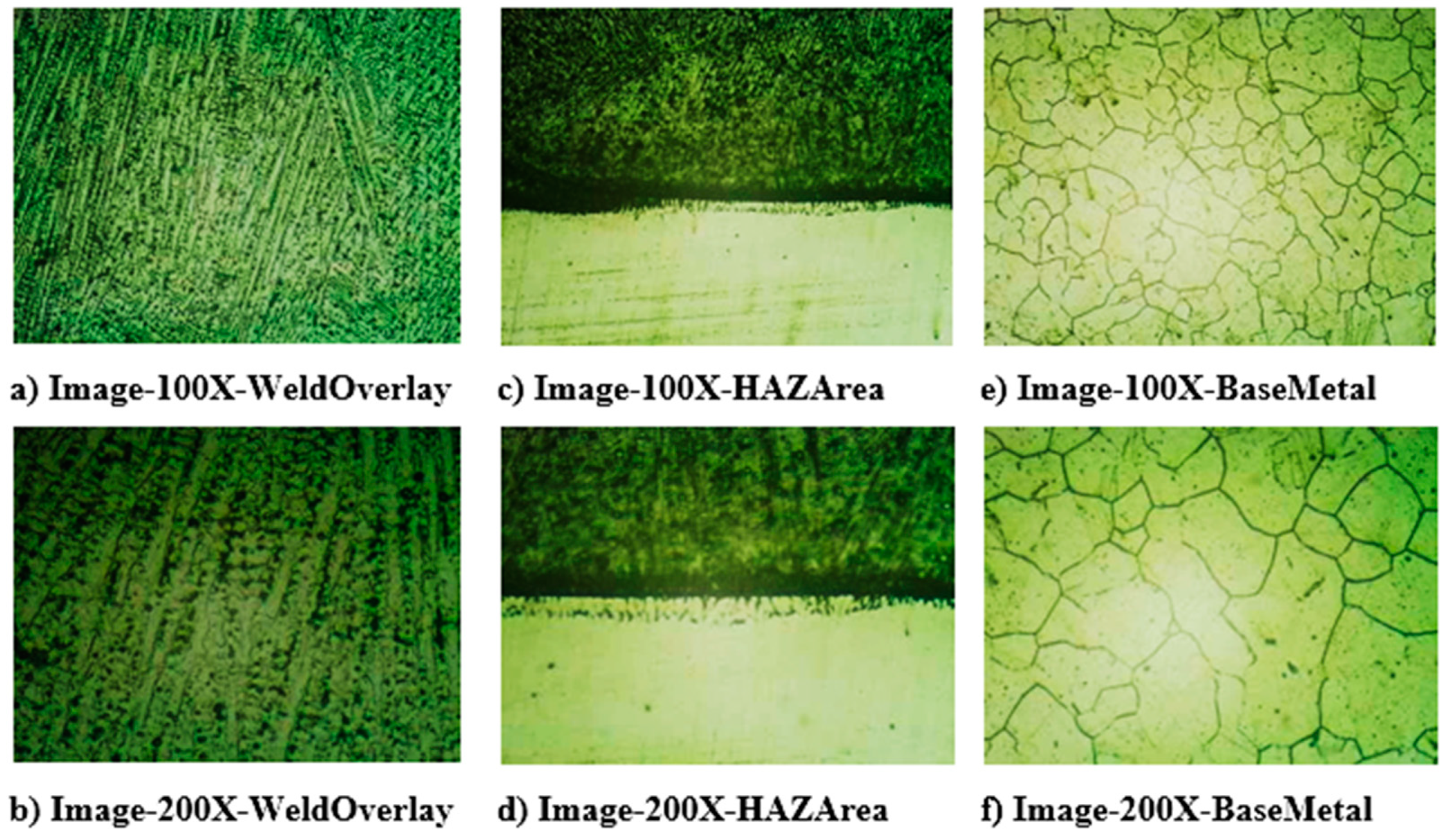
The microstructures of the weld overlay regions are shown in Figure 10. Figure 10a,b illustrate the morphology at 100× and 200× magnifications, respectively, of the deposited weld overlay. Figure 10c,d depict the 100× and 200× magnification morphologies of the heat-affected zone (HAZ) microstructure. Figure 10e,f display the microstructures of the base metal. In Figure 10c,d, it can be observed that a smooth fusion line or a distinct fusion bonding interface was achieved between the Hastelloy C-22 weld overlay and the SS 316L base metal. Additionally, due to the low heat input of the process, a small, insignificant HAZ was formed. Figure 10a–f showcase microstructures free of porosities, cracks, and other defects.
The formation of the microstructure primarily depends on factors such as alloy composition, the temperature gradient (G), the energy of the interface, and the solidification rate (R). The ratio G/R defines the morphology of the microstructure during solidification [49,50]. Figure 10a,b exhibit a fine columnar interdendritic microstructure in the weld overlay. The optical micrographs in Figure 10c,d demonstrate a minimal, negligible HAZ at the weld interface, base metal, and weld metal. The formation of this insignificant HAZ and the columnar interdendritic microstructure can be attributed to the low heat input associated with the laser welding process used in these trials. The micrograph of the base metal clearly shows the formation of an equiaxed austenite structure.
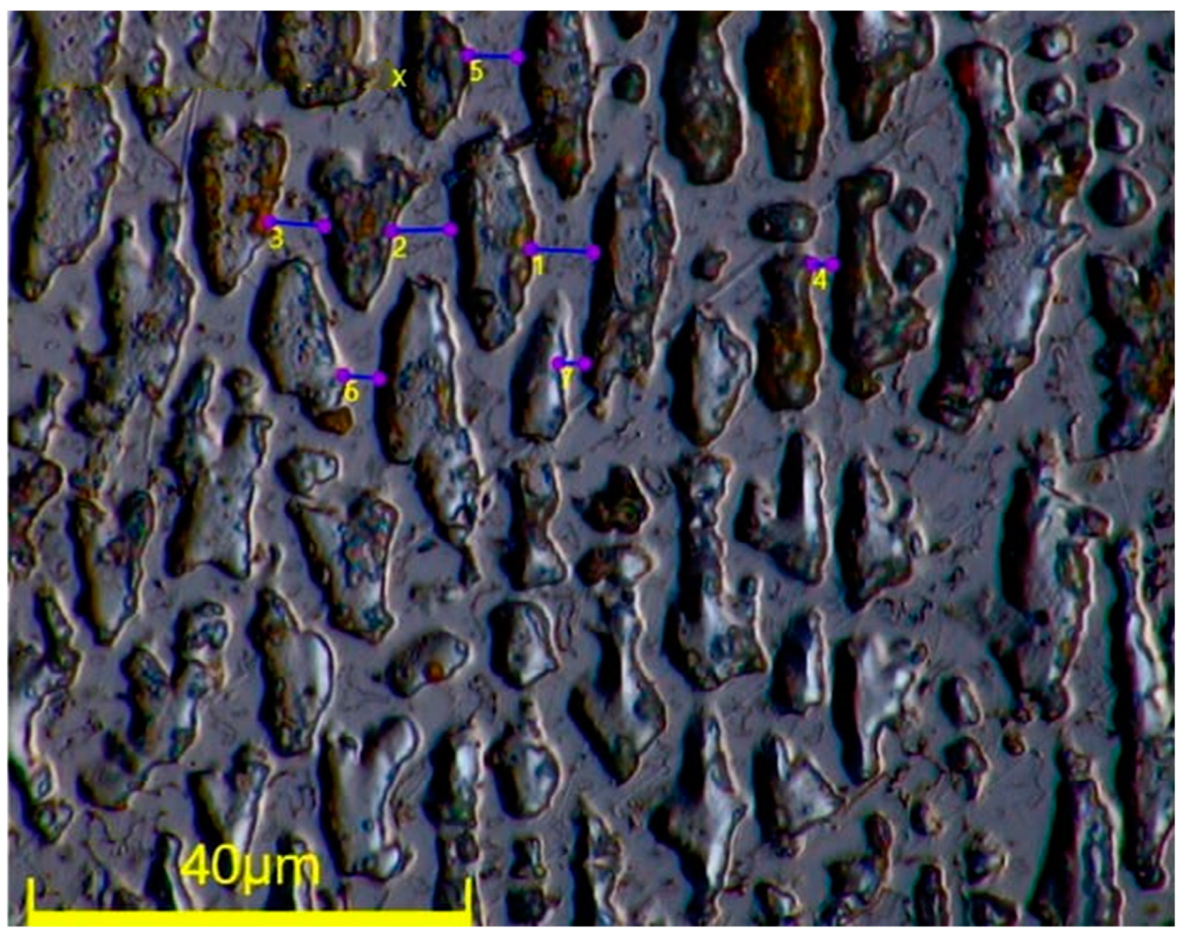
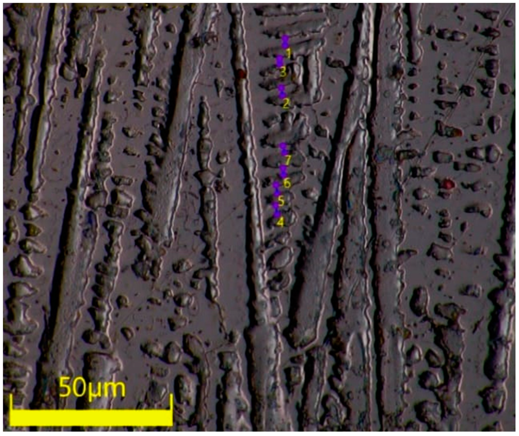
Table 3 and Table 4 present the average and individual values, respectively, of the primary and secondary interdendritic arm spacing, measured in µm. A difference in measurement values between primary and secondary dendrite arm spacing can be observed. The results indicate that the average value of the secondary arm spacing is comparatively smaller.
Figure 11 displays the primary dendritic arm spacing of the Hastelloy weld overlay, with a total of 7 readings taken. The maximum value of the primary dendritic arm spacing is 5.711 µm, while the minimum value is 1.809 µm. The average of these readings is 3.981 µm. In the laser deposition process, the high cooling rate of the melt pool, and consequently, the rapid solidification velocity, results in a close spacing of primary dendritic arms and secondary dendritic arm spacing [51,52].
Furthermore, due to the high solidification velocity of the melt pool, secondary dendrites grow properly, as depicted in Figure 12. The average value of secondary dendritic arm spacing obtained through the laser beam welding process is 2.289 µm. Smaller dendrite spacings are generally associated with finer grains and a more homogeneous microstructure, which can result in improved mechanical strength, hardness, and toughness. Finer dendrite spacings generally lead to improved corrosion resistance due to a more uniform distribution of alloying elements, reduced segregation, and minimized susceptibility to intergranular corrosion. Primary and secondary dendrite spacings can influence the integrity of the weld overlay [52].

3.7. Corrosion Potential Test

This study employed cyclic potentiodynamic polarization tests to examine the corrosion behavior of the Hastelloy C-22 weld overlay in a ferric sulfate–50% sulfuric acid solution, a selection aligned with ASTM G-28, Method-A. Samples 1, 2, and 3 offer valuable insights into the potential polarization behavior exhibited by the laser beam weld cladding of Hastelloy C-22 on SS 316L. To ensure a thorough assessment, samples were strategically extracted from diverse locations within the Hastelloy C-22 weld overlay. Each sample, measuring 1 cm × 1 cm, underwent exposure to the ferric sulfate–50% sulfuric acid solution. The resulting data, encompassing corrosion potential (Ecorr), corrosion current densities (Icorr), and anodic and cathodic Tafel slopes (βa and βc), are meticulously documented in Table 5. Upon carrying out a meticulous examination of the data presented in Table 5 and a comparative analysis with the corrosion rates at various locations of the Hastelloy C-22 weld overlay, it can be found that with the specified parameters of the weld overlay, the average corrosion rate achieved through laser beam welding on SS 316L is 1.20 mpy.

4. Conclusions

This research study aimed to investigate the utilization of Hastelloy C-22 powder for a weld overlay on SA 240 Type 316L using the laser beam welding process. The results and discussions provided valuable insights into the performance and characteristics of the weld overlay, with implications for its potential applications in the petrochemical industry.
The weld overlay of Hastelloy C-22 exhibited excellent weldability, as it displayed a clean surface without any welding flaws. However, some issues were observed at the starting and ending points of the automated welding process, which were attributed to setup problems in operational parameters. Overall, the surface quality of the weld overlay was deemed satisfactory.
The laser beam welding process achieved precise penetration of the Hastelloy weld overlay into the base metal, resulting in a defect-free weld overlay. This was confirmed through macro and visual examinations conducted on the weld overlay.
Bend test analysis confirmed the absence of cracks or holes in the welds, indicating the reliability and optimal parameters of the welding procedure. The integration between the cladding layer and the AISI 316L SS substrate was found to be satisfactory.
The hardness of the weld overlay increased compared to the base metal due to the development of a compact primary and secondary dendrite microstructure during welding. Hardness values in the heat-affected zone (HAZ) and at the interface were similar, indicating only a slight increase in hardness from the HAZ to the coating due to the small size of the HAZ.
Chemical composition analysis revealed that the weld overlay matched the desired composition of Hastelloy C-22 after a height of 0.5 mm from the base metal. At a height of 0.25 mm from the base metal, the composition of the weld overlay was similar to Hastelloy C-22, except for the Fe content in that region.
Microstructure analysis showed a defect-free weld overlay and an unchanged microstructure of the base metal. The laser welding process resulted in a minimal heat-affected zone and a fine columnar interdendritic microstructure, with average primary and secondary arm spacing values of 3.981 µm and 2.289 µm, respectively.
Corrosion potential testing indicated that the average corrosion rate of the Hastelloy C-22 weld overlay on SS 316L achieved through laser beam welding was 1.20 mpy, owing to the proper and uniform distribution of the cladding phase in the weld overlay region.
Overall, these findings highlight the successful utilization of Hastelloy C-22 powder for a weld overlay on SA 240 Type 316L using the laser beam welding process. This research contributes to our understanding of the weldability, structural integrity, hardness characteristics, process dilution, and corrosion resistance of this novel material combination. The results demonstrate the suitability of the weld overlay for applications in the petrochemical industry, pharmaceutical industry, and oil and gas industry, offering numerous benefits such as precise control, sound welds, high-quality finish, cost reduction, and streamlined production efficiency. Further research and optimization of welding parameters can enhance the performance and broaden the potential applications of this material combination.

Author Contributions

Conceptualization, M.V.M., M.D.C. and J.V.; methodology, M.V.M., M.D.C. and J.V.; software, R.C. and S.K.; validation, M.V.M., M.D.C. and J.V.; formal analysis, M.V.M., M.D.C. and J.V.; investigation, M.V.M., M.D.C., R.C., S.K. and J.V.; resources, M.V.M., M.D.C., R.C., S.K. and J.V.; data curation, M.V.M., M.D.C., R.C., S.K. and J.V.; writing—original draft preparation, M.V.M.; writing—review and editing, M.D.C. and J.V.; visualization, M.V.M., M.D.C. and J.V.; supervision, M.D.C. and J.V. All authors have read and agreed to the published version of the manuscript.

Funding

This research received no external funding.

Data Availability Statement

Data are contained within the article.

Acknowledgments

The authors are thankful to GMM Pfaudler Ltd., Karamsad, Anand, Gujarat, India, for providing the machines and materials that enabled us to perform the necessary experimental work.

Conflicts of Interest

The authors declare no conflict of interest.

References

  1. Mendes Da Mota, C.A.; Saldanha do Nascimento, A.; Neves Garcia, D.; Silva da Silva, D.A.; Ribeiro Teixeira, F.; Ferraresi, V.A. Nickel overlay deposited by MIG welding and cold wire MIG welding. Weld. Int. 2018, 32, 588–598. [Google Scholar] [CrossRef]
  2. Bray, J.W. Properties and Selection: Nonferrous Alloys and Special Purpose Materials; ASM Metals Handbook: Materials Park, OH, USA, 1990; Volume 92. [Google Scholar]
  3. Sharma, E.R.; Kumar, E.M.; Kamboj, D. Hastelloy C-276Weld overlay bySMAW process. Int. J. Eng. Res. Appl. 2017, 7, 86–91. [Google Scholar] [CrossRef]
  4. Lundin, C. Dissimilar metal welds-transition joints literature review. Weld. J. 1982, 61, 58–63. [Google Scholar]
  5. Scheid, A.; Oliveira, A.S.C.M.D. Analysis of PTA hardfacing with CoCrWC and CoCrMoSi alloys. Soldag. Inspeção 2013, 18, 322–328. [Google Scholar] [CrossRef]
  6. Gittos, M.; Gooch, T. Effect of iron dilution on corrosion resistance of Ni-Cr-Mo alloy cladding. Br. Corros. J. 1996, 31, 309–314. [Google Scholar] [CrossRef]
  7. Gatto, A.; Bassoli, E.; Fornari, M. Plasma Transferred Arc deposition of powdered high performances alloys: Process parameters optimisation as a function of alloy and geometrical configuration. Surf. Coat. Technol. 2004, 187, 265–271. [Google Scholar] [CrossRef]
  8. da Silva, M.M.; Batista, V.R.; Maciel, T.M.; dos Santos, M.A.; Brasileiro, T.L. Optimization of submerged arc welding process parameters for overlay welding. Weld. Int. 2018, 32, 122–129. [Google Scholar] [CrossRef]
  9. Shi, Y.; Yang, B.; Liaw, P.K. Corrosion-resistant high-entropy alloys: A review. Metals 2017, 7, 43. [Google Scholar] [CrossRef]
  10. Chaudhari, R.; Bhatt, R.; Vaghasia, V.; Raja, B.D.; Patel, V.K.; Khanna, S.; Vora, J.; Patel, V.V. A parametric study and experimental investigations of microstructure and mechanical properties of multi-layered structure of metal core wire using wire arc additive manufacturing. J. Adv. Join. Process. 2023, 8, 100160. [Google Scholar] [CrossRef]
  11. Deshmukh, D.; Kalyankar, V. Deposition Characteristics of Multitrack Overlayby Plasma Transferred Arc Welding on SS316Lwith Co-Cr Based Alloy–Influence ofProcess Parameters. High Temp. Mater. Process. 2019, 38, 248–263. [Google Scholar] [CrossRef]
  12. Ferreira Filho, D.; Souza, D.; Gonçalves Júnior, J.L.; Reis, R.P.; Da Silva Junior, W.M.; Tavares, A.F. Influence of Substrate on the Tribological Behavior of Inconel 625 GMAW Overlays. Coatings 2023, 13, 1454. [Google Scholar] [CrossRef]
  13. Songya, T.; Saifan, A.; Pengqian, G.; Dawy, I.; Saleh, B. Development of an automatic welding system for the boiler tube walls weld overlay. Metals 2020, 10, 1241. [Google Scholar] [CrossRef]
  14. Ranjan, R.; Das, A.K. Protection from corrosion and wear by different weld cladding techniques: A review. Mater. Today Proc. 2022, 57, 1687–1693. [Google Scholar] [CrossRef]
  15. Sim, B.-M.; Hong, T.-S.; Hanim, M.A.-A.; Tchan, E.-J.N.; Talari, M.-K. The influence of post weld heat treatment precipitation on duplex stainless steels weld overlay towards pitting corrosion. Materials 2019, 12, 3285. [Google Scholar] [CrossRef]
  16. Chotěborský, R.; Navrátilová, M.; Hrabě, P. Effects of MIG process parameters on the geometry and dilution of the bead in the automatic surfacing. Res. Agric. Eng. 2011, 57, 56–62. [Google Scholar] [CrossRef]
  17. Palani, P.; Murugan, N. Optimization of weld bead geometry for stainless steel claddings deposited by FCAW. J. Mater. Process. Technol. 2007, 190, 291–299. [Google Scholar] [CrossRef]
  18. Sowrirajan, M.; Koshy Mathews, P.; Vijayan, S. Simultaneous multi-objective optimization of stainless steel clad layer on pressure vessels using genetic algorithm. J. Mech. Sci. Technol. 2018, 32, 2559–2568. [Google Scholar] [CrossRef]
  19. Kannan, T.; Yoganandh, J. Effect of process parameters on clad bead geometry and its shape relationships of stainless steel claddings deposited by GMAW. Int. J. Adv. Manuf. Technol. 2010, 47, 1083–1095. [Google Scholar] [CrossRef]
  20. Lin, C.-M.; Su, T.-L.; Wu, K.-Y. Effects of parameter optimization on microstructure and properties of GTAW clad welding on AISI 304L stainless steel using Inconel 52M. Int. J. Adv. Manuf. Technol. 2015, 79, 2057–2066. [Google Scholar] [CrossRef]
  21. Wang, Q.-Y.; Zhang, X.-S.; Zheng, H.-B.; Liu, T.-Y.; Dong, L.-J.; Zhang, J.; Xi, Y.-C.; Zeng, D.-Z.; Lin, Y.-H.; Luo, H. Intergranular corrosion mechanism of sub-grain in laser additive manufactured Hastelloy C22 induced by heat treatment. Appl. Surf. Sci. 2023, 608, 155140. [Google Scholar] [CrossRef]
  22. Prem Kumar, M.; Arivazhagan, N.; Chiranjeevi, C.; Raja Sekhar, Y.; Babu, N.; Manikandan, M. Effect of Molten Binary Salt on Inconel 600 and Hastelloy C-276 Superalloys for Thermal Energy Storage Systems: A Corrosion Study. J. Mater. Eng. Perform. 2023, 1–14. [Google Scholar] [CrossRef]
  23. Nowicki, R.; Świercz, R.; Oniszczuk-Świercz, D.; Rozenek, M. Experimental Investigation of Technological Indicators and Surface Roughness of Hastelloy C-22 after Electrical Discharge Machining Using POCO Graphite Electrodes. Materials 2022, 15, 5631. [Google Scholar] [CrossRef] [PubMed]
  24. Patel, D.; Jani, S.; Shah, D. Augmentation in depth of penetration of hastelloy C-22 by FATIG welding. Adv. Ind. Manuf. Eng. 2022, 4, 100081. [Google Scholar] [CrossRef]
  25. Zheng, C.; Liu, Z.; Liu, Q.; Li, Y.; Liu, C. Comparative investigation on corrosion behavior of laser cladding C22 coating, Hastelloy C22 alloy and Ti–6Al–4V alloy in simulated desulfurized flue gas condensates. J. Mater. Res. Technol. 2022, 18, 2194–2207. [Google Scholar] [CrossRef]
  26. Zhou, S.; Ma, G.; Dongjiang, W.; Chai, D.; Lei, M. Ultrasonic vibration assisted laser welding of nickel-based alloy and Austenite stainless steel. J. Manuf. Process. 2018, 31, 759–767. [Google Scholar] [CrossRef]
  27. Advaith, V.; Vaisikan, A.; Thirumalini, S.; Padmanaban, R.; Arivarasu, M.; Prabhu, T.R. Comparative studies on pulsed GTAW and AGTAW on dissimilar alloy C-22 and AISI 316L weldments. Mater. Today Proc. 2020, 27, 2886–2895. [Google Scholar] [CrossRef]
  28. Kumar, A.; Ramkumar, P.; Shukla, A.; Gupta, N. Prediction of Mechanical Properties in Rotational Moulding of LLDPE Using Machine Learning Model for the Given Oven Residence Time. In Proceedings of the Recent Advances in Mechanical Infrastructure: Proceedings of ICRAM 2020, Ahmedabad, India, 22–23 August 2020; pp. 3–12. [Google Scholar]
  29. Committee, A. Specification for Chromium and Chromium-Nickel Stainless Steel Plate, Sheet, and Strip for Pressure Vessels and for General Applications; ASTM International: Materials Park, OH, USA, 2023. [Google Scholar]
  30. Acherjee, B. Laser transmission welding of polymers–a review on welding parameters, quality attributes, process monitoring, and applications. J. Manuf. Process. 2021, 64, 421–443. [Google Scholar] [CrossRef]
  31. Yoon, B.H.; Ahn, Y.S.; Lee, C.H. The effect of dilution on HAZ liquation cracking in PTAW Ni-base superalloys overlay deposit. ISIJ Int. 2002, 42, 178–183. [Google Scholar] [CrossRef]
  32. Neyka, S.; Kusch, M.; Mayr, P. Progress in high performance hardfacing processes Tandem-Gas-Metal-Arc-Welding and Plasma-MIG Hybrid welding. In Proceedings of the 9th International Conference, Chicago, IL, USA, 11–14 August 2013. [Google Scholar]
  33. Chattopadhyay, P.; van der Mee, V.; Zhang, Z. Hybrid electroslag cladding (H-ESC): An innovation in high speed electroslag strip cladding. Weld. World 2019, 63, 663–672. [Google Scholar] [CrossRef]
  34. Deng, H.; Shi, H.; Tsuruoka, S. Influence of coating thickness and temperature on mechanical properties of steel deposited with Co-based alloy hardfacing coating. Surf. Coat. Technol. 2010, 204, 3927–3934. [Google Scholar] [CrossRef]
  35. Balasubramanian, V.; Varahamoorthy, R.; Ramachandran, C.; Muralidharan, C. Selection of welding process for hardfacing on carbon steels based on quantitative and qualitative factors. Int. J. Adv. Manuf. Technol. 2009, 40, 887–897. [Google Scholar] [CrossRef]
  36. Sudha, C.; Shankar, P.; Rao, R.S.; Thirumurugesan, R.; Vijayalakshmi, M.; Raj, B. Microchemical and microstructural studies in a PTA weld overlay of Ni–Cr–Si–B alloy on AISI 304L stainless steel. Surf. Coat. Technol. 2008, 202, 2103–2112. [Google Scholar] [CrossRef]
  37. Gontcharov, A.; Tian, Y.; Lowden, P.; Brochu, M. Mechanical properties and structure of laser beam and wide gap brazed joints produced using Mar M247–Amdry DF3 powders. J. Eng. Gas Turbines Power 2019, 141, 041031. [Google Scholar] [CrossRef]
  38. Prasath, N.E.; Selvabharathi, R. Influence of Plasma Transfer Arc Cladding of NiCrBFe filler powder on microstructure and tensile properties of Titanium Grade 2 and Ti 6Al-4V alloy dissimilar joint prepared by laser beam welding. Opt. Laser Technol. 2020, 128, 106206. [Google Scholar] [CrossRef]
  39. Vora, J.; Parmar, H.; Chaudhari, R.; Khanna, S.; Doshi, M.; Patel, V. Experimental investigations on mechanical properties of multi-layered structure fabricated by GMAW-based WAAM of SS316L. J. Mater. Res. Technol. 2022, 20, 2748–2757. [Google Scholar] [CrossRef]
  40. Chaudhari, R.; Parmar, H.; Vora, J.; Patel, V.K. Parametric study and investigations of bead geometries of GMAW-based wire–arc additive manufacturing of 316L stainless steels. Metals 2022, 12, 1232. [Google Scholar] [CrossRef]
  41. Vora, J.; Pandey, R.; Dodiya, P.; Patel, V.; Khanna, S.; Vaghasia, V.; Chaudhari, R. Fabrication of Multi-Walled Structure through Parametric Study of Bead Geometries of GMAW-Based WAAM Process of SS309L. Materials 2023, 16, 5147. [Google Scholar] [CrossRef]
  42. d’Oliveira, A.; Vilar, R.; Feder, C. High temperature behaviour of plasma transferred arc and laser Co-based alloy coatings. Appl. Surf. Sci. 2002, 201, 154–160. [Google Scholar] [CrossRef]
  43. Wang, Q.-Y.; Zhang, Y.-F.; Bai, S.-L.; Liu, Z.-D. Microstructures, mechanical properties and corrosion resistance of Hastelloy C22 coating produced by laser cladding. J. Alloys Compd. 2013, 553, 253–258. [Google Scholar] [CrossRef]
  44. Alvarães, C.P.; Madalena, F.C.A.; Souza, L.F.G.D.; Jorge, J.C.F.; Araújo, L.S.; Mendes, M.C. Performance of the INCONEL 625 alloy weld overlay obtained by FCAW process. Matéria 2019, 24. [Google Scholar] [CrossRef]
  45. Tahaei, A.; Vazquez, F.G.; Merlin, M.; Arizmendi-Morquecho, A.; Valdes, F.A.R.; Garagnani, G.L. Metallurgical characterization of a weld bead coating applied by the PTA process on the D2 tool steel. Soldag. Inspeção 2016, 21, 209–219. [Google Scholar] [CrossRef]
  46. Ahmad, M.; Akhter, J.; Akhtar, M.; Iqbal, M.; Ahmed, E.; Choudhry, M. Microstructure and hardness studies of the electron beam welded zone of Hastelloy C-276. J. Alloys Compd. 2005, 390, 88–93. [Google Scholar] [CrossRef]
  47. Xu, G.; Kutsuna, M.; Liu, Z.; Zhang, H. Characteristics of Ni-based coating layer formed by laser and plasma cladding processes. Mater. Sci. Eng. A 2006, 417, 63–72. [Google Scholar] [CrossRef]
  48. Antoszczyszyn, T.J.; Paes, R.M.G.; Oliveira, A.S.C.M.D.; Scheid, A. Impact of dilution on the microstructure and properties of Ni-based 625 alloy coatings. Soldag. Inspeção 2014, 19, 134–144. [Google Scholar] [CrossRef]
  49. Varghese, P.; Vetrivendan, E.; Dash, M.K.; Ningshen, S.; Kamaraj, M.; Mudali, U.K. Weld overlay coating of Inconel 617 M on type 316 L stainless steel by cold metal transfer process. Surf. Coat. Technol. 2019, 357, 1004–1013. [Google Scholar] [CrossRef]
  50. Toyserkani, E.; Khajepour, A.; Corbin, S.F. Laser Cladding; CRC Press: Boca Raton, FL, USA, 2004. [Google Scholar]
  51. Yaedu, A.; D’Oliveira, A. Cobalt based alloy PTA hardfacing on different substrate steels. Mater. Sci. Technol. 2005, 21, 459–466. [Google Scholar] [CrossRef]
  52. Miná, É.M.; Da Silva, Y.C.; Dille, J.; Silva, C.C. The effect of dilution on microsegregation in AWS ER NiCrMo-14 alloy welding claddings. Metall. Mater. Trans. A 2016, 47, 6138–6147. [Google Scholar] [CrossRef]
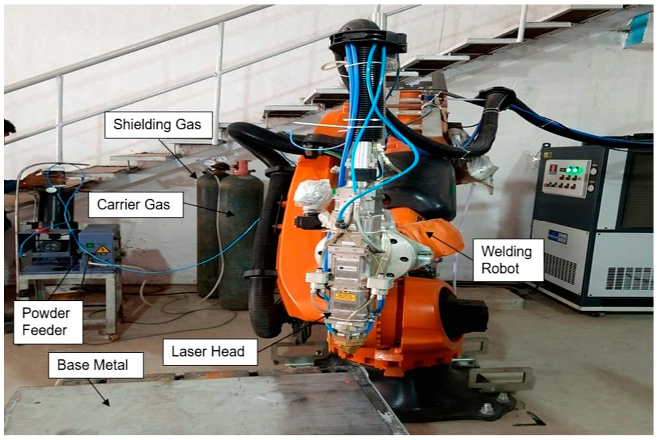
Figure 1. Experimental setup for laser beam weld overlay.
Jmmp 07 00207 g001
Figure 2. Weld overlay of Hastelloy C-22 alloy.
Jmmp 07 00207 g002
Figure 3. Locations of hardness indentations.
Jmmp 07 00207 g003
Figure 4. Top view of Hastelloy C-22 weld overlay on SS-316L.
Jmmp 07 00207 g004
Figure 5. Top view of Hastelloy C-22 weld overlay.
Jmmp 07 00207 g005
Figure 6. Hastelloy weld overlay bend test using LBW.
Jmmp 07 00207 g006
Figure 7. Vickers hardness along the Hastelloy C-22 weld overlay on SS-316L.
Jmmp 07 00207 g007
Figure 8. Chemical composition gradient.
Jmmp 07 00207 g008
Figure 9. Stitching image of Hastelloy weld overlay of C-22 on SS-316L.
Jmmp 07 00207 g009
Figure 10. Microstructure analysis of Hastelloy C-22 weld overlay on SS-316L.
Jmmp 07 00207 g010
Figure 11. Primary dendritic arm spacing of Hastelloy weld overlay when using LBW.
Jmmp 07 00207 g011
Figure 12. Secondary dendritic arm spacing of Hastelloy Weld Overlay by LBW.
Jmmp 07 00207 g012
Table 1. Chemical composition (wt. %) of SA 240 Type 316L steel and Hastelloy C-22 powder.
ElementsCSiMnPSCrMoNiFeNCoW
SA 240 Type 316L0.0230.31.260.0430.00416.252.0310.05Bal.0.038--
Hastelloy C-22 Powder0.0070.1-0.010.0123.514.84Bal.3.10.090.13.5
Table 2. Welding parameters.
ParameterLayer-1Layer-2
Power2.5 KW3.0 KW
Travel speed200 mm/min170 mm/min
Carrier gas flow6 LPM6 LPM
Shielding gas flow25 LPM25 LPM
Powder feed rate1.6 disc rpm1.6 disc rpm
Type of WeldWeavingWeaving
Carrier gasArgon (99.99% purity)Argon (99.99% purity)
Shielding gasArgon (99.99% purity)Argon (99.99% purity)
Welding position1 G (Flat)1 G (Flat)
Focus height25 mm25 mm
Laser spot size6 mm6 mm
No. of beads/layer 77
Table 3. Primary dendritic arm spacing.
Sr. No1234567Average
Value (µm)5.7115.2895.0261.8094.4543.2122.3653.981
Table 4. Secondary dendritic arm spacing with LBW process.
Sr. No1234567Average
Value (µm)2.0872.3581.7312.7392.7452.0862.2782.289
Table 5. Corrosion potential test results.
ParameterObservation
Sample 1Sample 2Sample 3
Sample Size (cm)1 L × 1 W1 L × 1 W1 L × 1 W
Test SolutionFerric Sulfate + Sulfuric AcidFerric Sulfate + Sulfuric AcidFerric Sulfate + Sulfuric Acid
Beta A (V/decade)217.7 × 10−3335.0 × 10−3277.2 × 10−3
Beta C (V/decade)74.50 × 10−361.00 × 10−373.70 × 10⁻³
Corrosion Current (Icorr)745.0 (nA)3.100 (µA)3.190 (µA)
Corrosion Potential (Ecorr) (mV)761.0785.0770.0
Corrosion Rate (mpy)0.3791.581.63
Disclaimer/Publisher’s Note: The statements, opinions and data contained in all publications are solely those of the individual author(s) and contributor(s) and not of MDPI and/or the editor(s). MDPI and/or the editor(s) disclaim responsibility for any injury to people or property resulting from any ideas, methods, instructions or products referred to in the content.