Article

Evaluation of Microstructure–Porosity–Hardness of Thermal Plasma-Sprayed NiTi Coating Layers

FZU-Institute of Physics of Czech Academy of Science, Na Slovance 1999/2, 18200 Prague, Czech Republic
*
Author to whom correspondence should be addressed.
J. Manuf. Mater. Process. 2023, 7(6), 198; https://doi.org/10.3390/jmmp7060198
Submission received: 13 October 2023 / Revised: 27 October 2023 / Accepted: 1 November 2023 / Published: 7 November 2023

Abstract

:
The quality of NiTi coating influences the thermal, microstructural, and mechanical behavior of the material produced by plasma spraying. To understand the behavior of the coating, the study has been designed and planned at two different plasma powers with various feed rates. NiTi as shape memory layers emerge as promising protective coatings on the surface of substrates against corrosion or wear. In the present investigation, NiTi multilayers were produced by thermal plasma spraying using NiTi (50 at. %) powder as the feedstock material. This work illustrates the studies of the microstructure, porosity of the coating layers, phase detection, hardness values, shape memory behavior, and the formation of samples produced by different spraying parameters. The porosity within coating layers has been analyzed based on the various shape factors of pores that correlate with the hardness and mechanical behavior of the samples. This work will explore the quality of the coating in terms of its porosity and compactness, which will affect the performance of the shape memory behavior. The functional coating of NiTi will have a significant influence on the durability of the material’s performance against corrosion.

1. Introduction

NiTi as a functional coating provides a prospective future application in improving materials’ surface properties, increasing their lifetime, repairing the damaged metallic parts in areas of erosion, and affecting their corrosion behavior [1,2,3]. The materials’ performance will be enriched with a thin coating layer of NiTi added to the surface as a protective barrier against corrosion and erosion issues. The coating could be achieved through powder metallurgical routes using the thermal plasma-spraying method [4,5]. Thermal plasma spraying has emerged as a potential method for both the deposition of coatings and the fabrication of parts from metals and alloy powders. The properties of plasma-sprayed coatings such as their quality and compact nature affect the materials in terms of their durability, thermal conductivity, resistance against thermal cycling, fatigue behavior, and the overall strength of the material [6,7,8]. The performance of the coating depends upon the quality of the coating layers formed without any porosity. Porosity develops in the coating layer during the spraying of the melted powder on the substrate. The spraying parameters influence the melting of the powder and deposition efficiency on the substrate which creates a layer of deposition along the cross-section for the formation of coating layers. However, little investigation has been conducted on the porosity of coatings as a function of spraying parameters, and few works have been published in these areas [9,10]. Some reviews indicate it is possible to reduce porosity significantly in the coating layers by controlling the spraying parameter. The effect of the processing parameters influences pores, and the sensitivity of porous architecture also affects the coating behavior in the material [11,12,13]. Some researchers mentioned that the effect of spraying variables or parameters strongly influences the density of the hard coatings [14,15]. The porosity value is unlikely to be predictable before applying a coat, by the spraying process, with a variety of mechanical and thermo-physical properties [16,17,18]. Plasma-sprayed coats shows various classifications of porosity such as open, closed, series of open porosity, and clusters of open porosity, which lead to total porosity within the coating layers [19,20]. The porosity within plasma-sprayed coating layers is correlated with the microstructure of the coating layers in the thickness and surface areas [21,22,23]. The samples are considered for the investigation of the coating with and without a substrate.
The quantity and morphology of the porosity are crucial to the physical and mechanical properties of the coatings [24,25]. In the plasma-spraying process, the NiTi particles are molten and accelerated for their impact on the substrate, where rapid solidification and deposition build-up occur. Generally, the porosity in plasma-sprayed coating has been categorized by three sources of origin. Interlamellar pores and globular or irregular pores are caused by imperfect contact, and partially molten particles as well as intersplat cracks are due to stress relaxation. However, these porosities in plasma spray coating can be minimized by optimizing the spray parameters, for instance, the plasma input power, feed rate, number of spray passes, stand-off distance, preheating, etc. In multilayered coating, the layers are formed of more than one identical layer on the substrate. The function of multilayer coating is to reduce the chance of defects such as microcracks or pores propagating through the layers [26,27]. Multilayered coatings improve the interface layers, which could provide the transition from the substrate to the adjoining layers with better adhesion, with a smoother transition with additional layers [28,29,30].
Although the porosity generated during plasma spraying has been considered a common concept, there is hardly any correlation regarding the microstructure–porosity–hardness behavior of the coatings [31,32]. In this work, the spraying variables have been altered to obtain a compact structure with reduced porosity. However, retaining the shape memory effect during the spraying process is a main factor taken into consideration. The phases that develop in the coating during spraying will contribute towards the shape memory behavior. In this work, the porosity is analyzed briefly in the coating layers, with the corresponding shape and size of pores leading to the quality of the coating being predicted. The hardness of the coating at the surface and along the cross-section is determined with the investigation of the phases that lead to the shape memory behavior. The quality of the NiTi coating influences the thermal, microstructural, and mechanical behavior of the material produced by plasma spraying. To understand the behavior of the coating, a study has been designed and planned at two different plasma powers with various feed rates. NiTi as shape memory layers emerges as a promising application as a protective coating on the surface of the substrate against corrosion or wear. In the present investigation, NiTi multilayers were produced by thermal plasma spraying using NiTi (50 at. %) powder as the feedstock material. This work illustrates the studies of the microstructure, porosity of the coating layers, phase detection, hardness values, shape memory behavior, and the formation of samples produced by different spraying parameters. The porosity within the coating layers has been analyzed based on the various shape factors of pores that correlate with the hardness and mechanical behavior of the samples. This work will explore the quality of the coating in terms of its porosity and compactness, which will affect the performance of the shape memory behavior. The functional coating of NiTi will have a significant influence on the durability of the material’s performance against corrosion.

2. Materials and Method

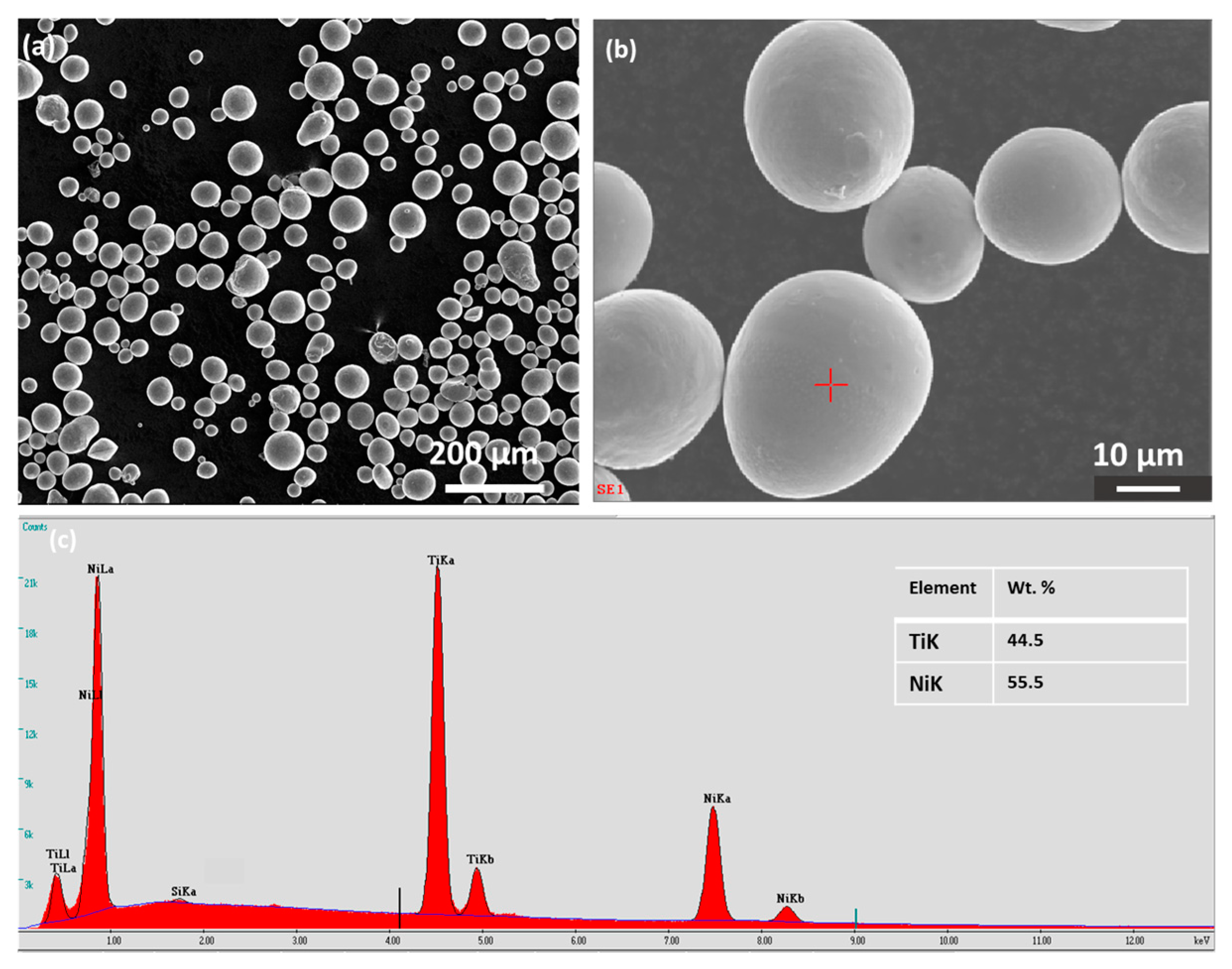
2.1. Feedstock Powder of NiTi for Spraying

Ni50Ti50 particles were purchased from American Elements MERELEX Corporation (Los Angeles, CA, USA) with a purity of 99.5% for plasma spraying. The particles are spherical and gas-atomized and sizes range from 20 to 63 µm with an elemental composition of Ni: Ti (50:50 at. %). The chemical composition is provided by the manufacturer, with the following analysis of the minor elements: (%) Fe ≤ 0.01, Al ≤ 0.001, Cu ≤ 0.002, Si ≤ 0.001, Ca ≤ 0.001, C ≤ 0.004, O ≤ 0.07, N ≤ 0.005. (American Elements, MERELEX Corporation, Los Angeles, CA, USA) [5,30]. Figure 1a,b show the particles’ dispersion, with an enlarged view of the particles. The red mark in Figure 1b indicates the energy dispersive X-ray analysis (EDX) for particle composition, which is represented in Figure 1c.

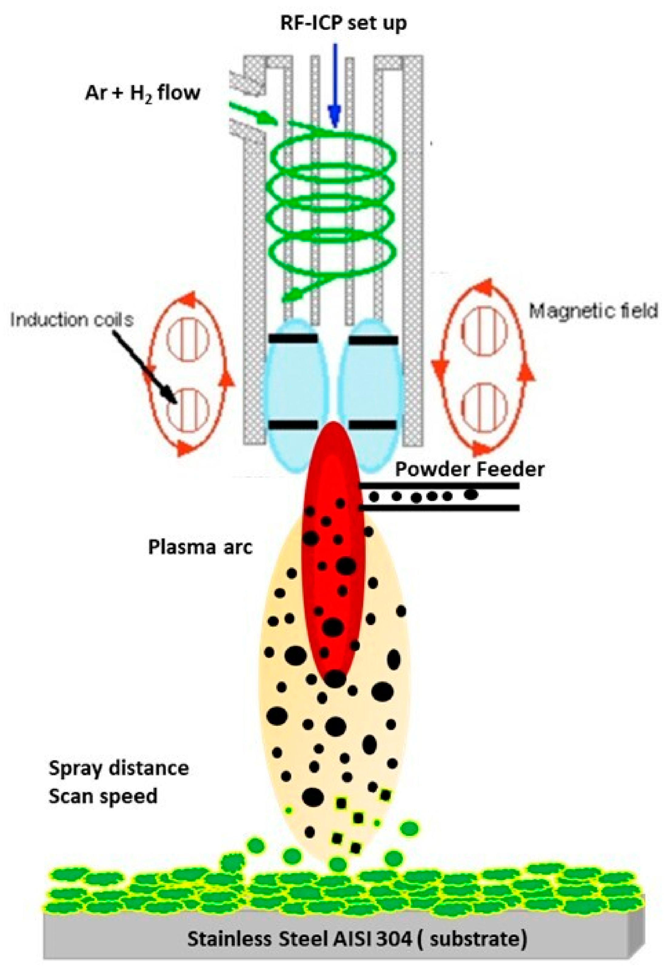
2.2. Plasma-Spraying Process and Process Parameters for Sample Preparation

The NiTi powder was sprayed on the surface of the substrate of stainless steel by using a facility from the Institute of Plasma Physics of the Czech Academy of Science. The radio frequency inductively coupled plasma reactor was used for plasma spraying. The substrate was chosen as rectangular-shaped stainless steel of 60 × 20 × 3 mm. The top surface of the substrate was polished and cleaned with acetone before use for spraying. Table 1 shows the experimental parameters that are considered for various spraying processes for coating. The plasma spraying for the impact of the molten particles on the deposition of coating for the preparation of a multilayered coating is shown in Figure 2. Four samples were considered for the study. The input power was initially selected at 9 k and a feed rate of 4.1 g/min, with a moving speed of 2 mm/s, which is reduced to 1 mm/s for the second sample, keeping the rest of the parameters the same. However, the third sample is prepared by spraying with a lower feed rate of 2.1 g/min, keeping the speed the same as in sample 1. In sample 4, power is increased to 12 kW while keeping a lower feed rate of 2.1 g/min. Each sample was sprayed with six layers of coating on the substrate. However, the net powder spray time for samples 1 and 2 was chosen at 180 s, which leads to a thicker coating. However, samples 3 and 4 had a shorter spray time, which leads to a thinner coating than those samples. The coating exhibits a significantly higher hardness than NiTi commercial alloy (230–277 HV), measured by microindentation, while maintaining the ability to plastically deform during microindentation experiments without apparent cracking or spallation (Table 1). The flexibility and scalability of the dealloying process used here demonstrate a promising route towards protective coatings for structural alloys [11].

2.3. Characterization of Plasma Coating Samples
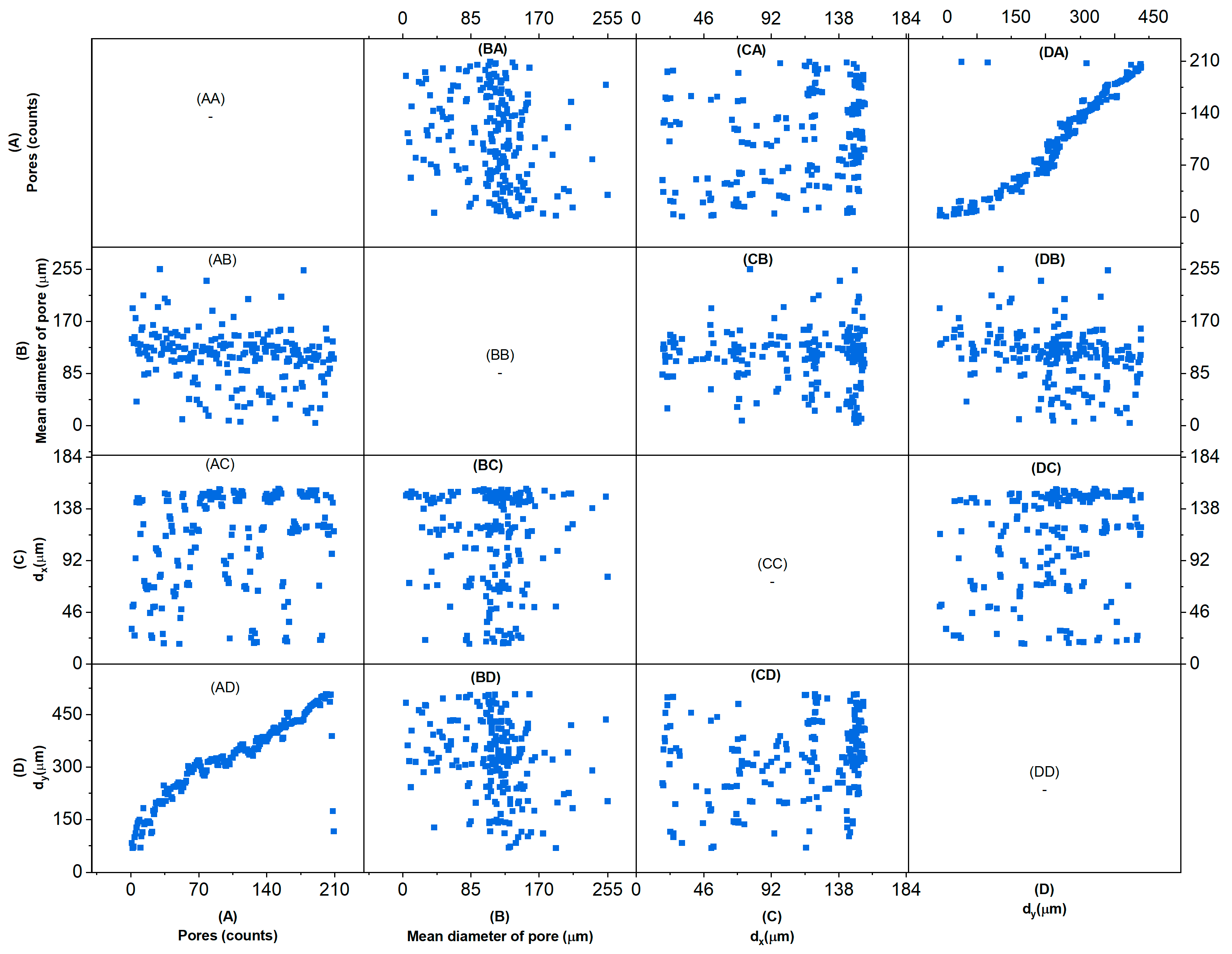
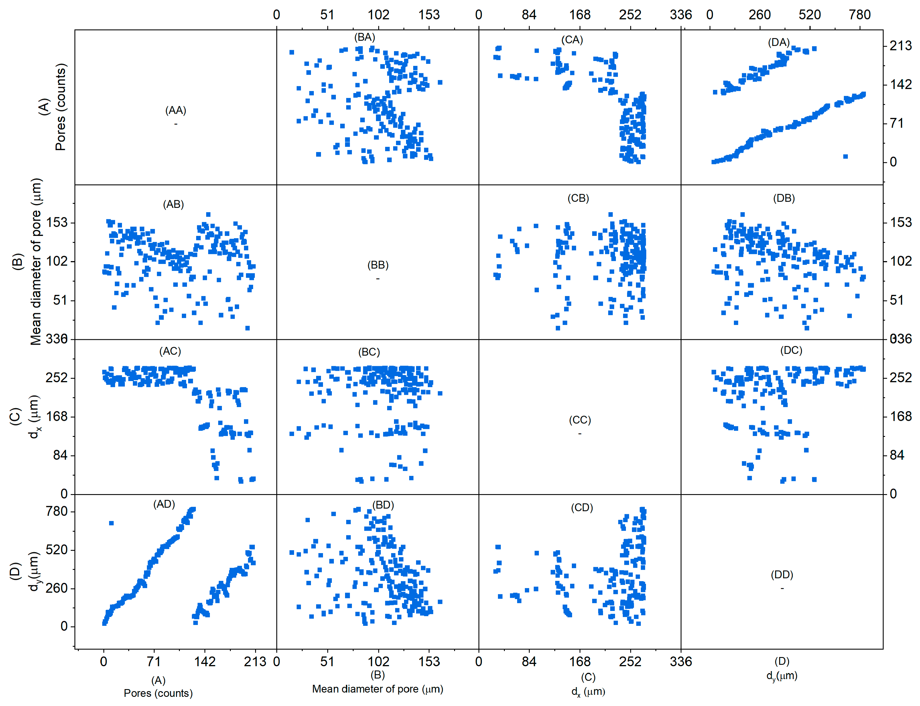
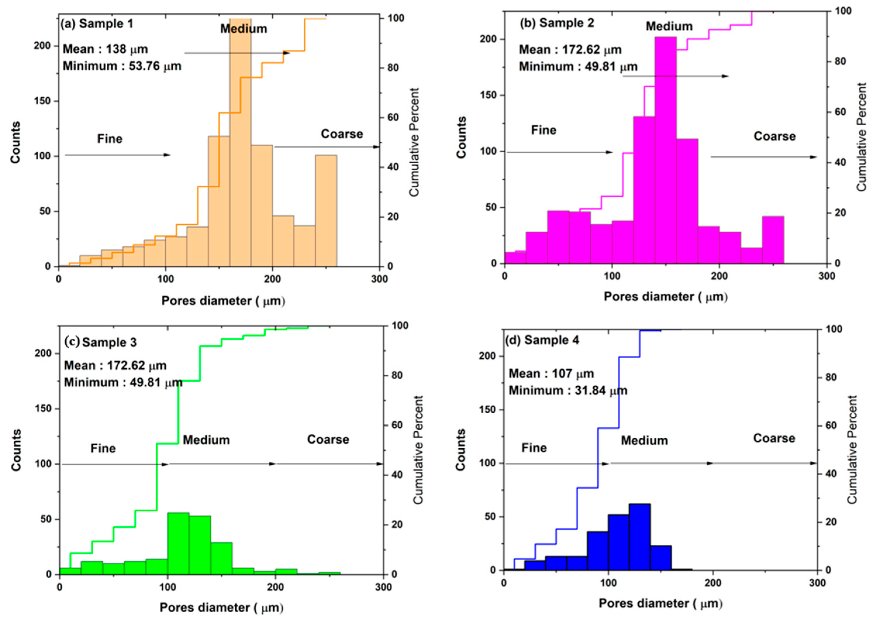
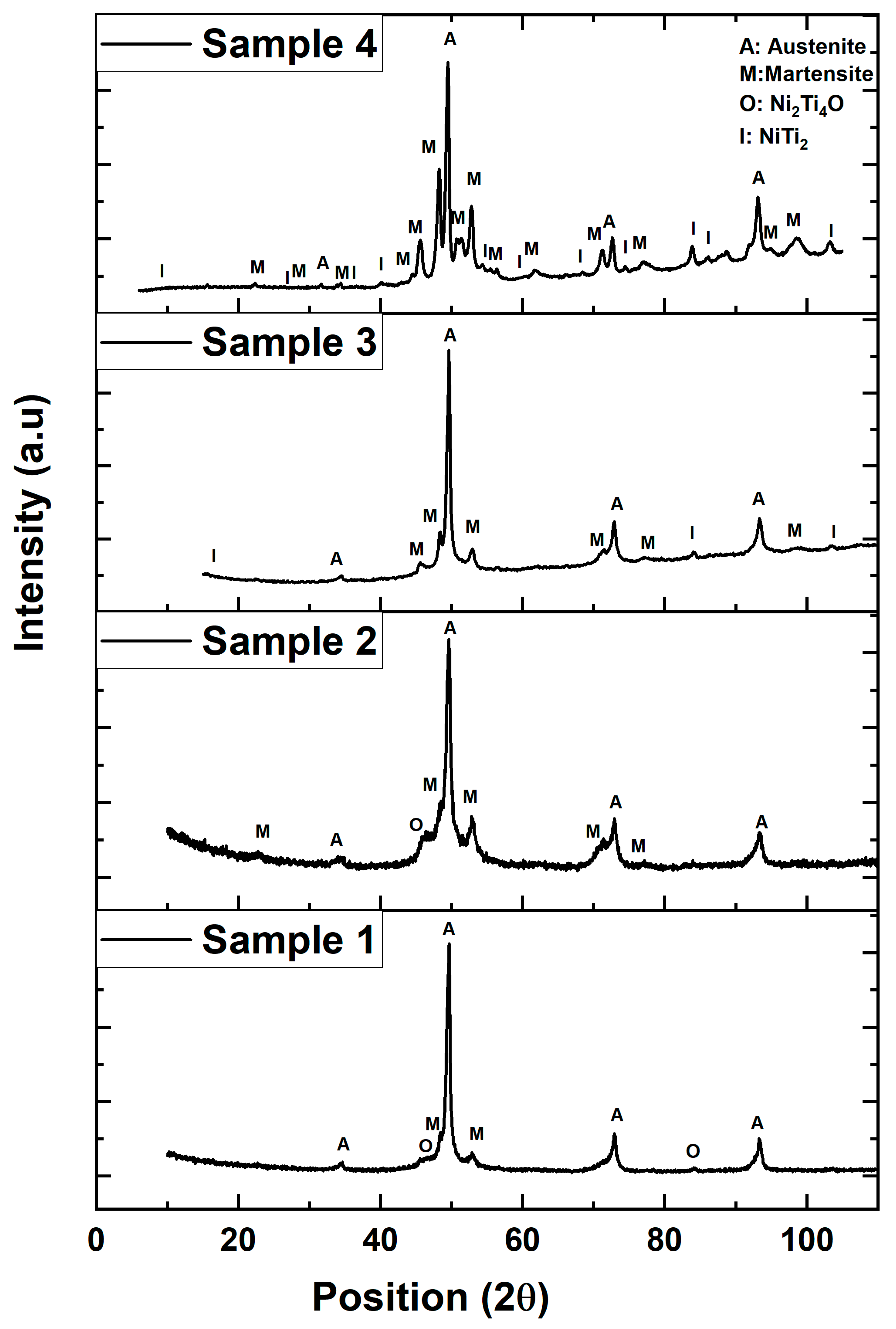
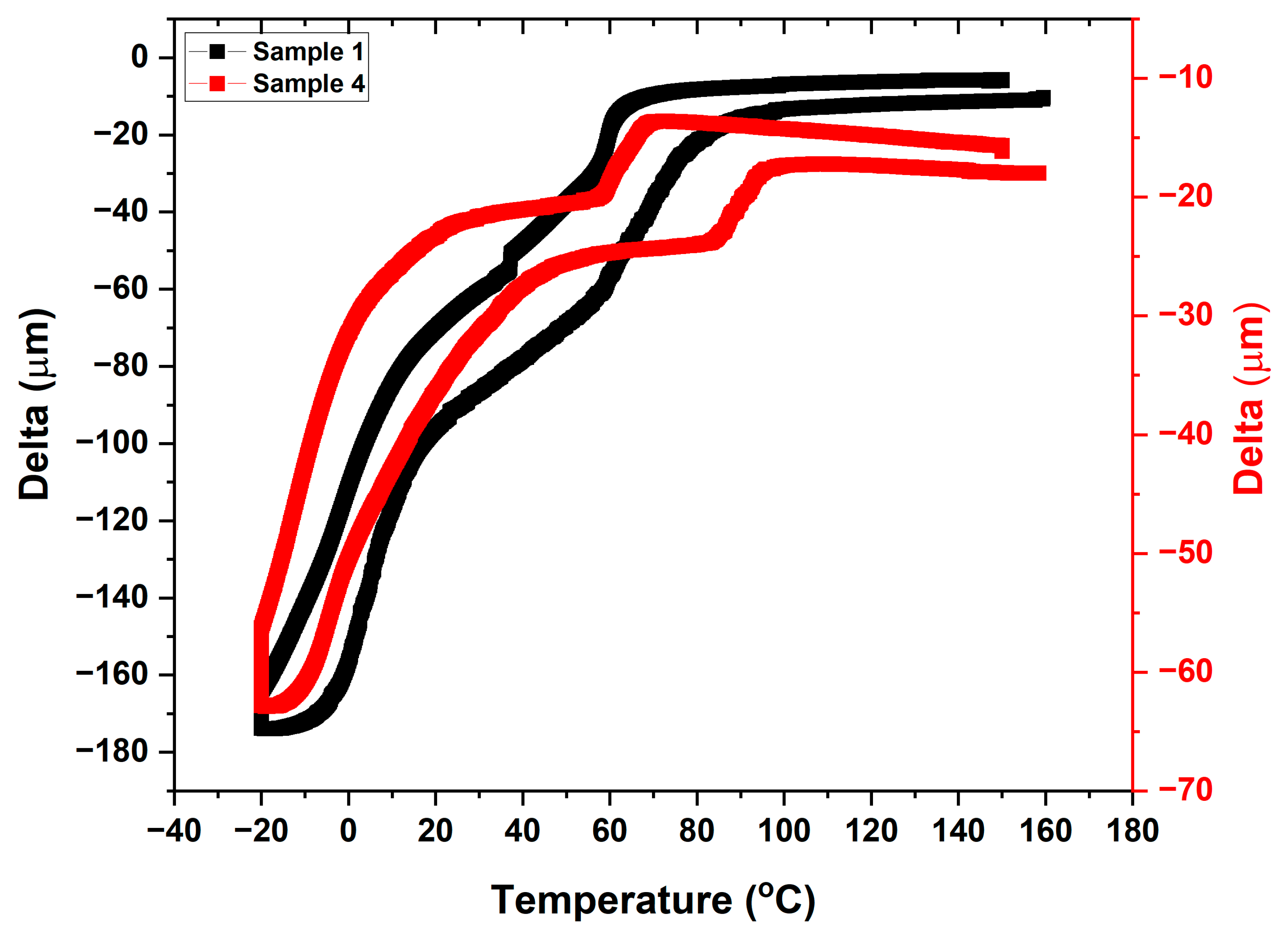
The characterization of NiTi coating was carried out with and without any substrate. The samples were prepared from the bulk coating by using an electric discharge machine cutter. The substrate of 100 µm thickness was kept attached with a coating for microstructural characterization along the thickness. The coating was separated from the substrate by cutting. The samples were polished, and the surface was mirror polished by using a diamond suspension of 1 µm for the surface image examination. The surface and cross-section were etched by using the etchant (HF: HNO3: H2O) to reveal the microstructure under an optical microscope. The sample preparation for metallographic examination is followed by grinding with standard ANSI grit (SiC abrasive) from 400 to 1200 grit with diamond polishing from 6- to 1-micron diamond paste. The final polishing was carried out with an OPS solution to reveal the microstructure. The microstructure of the NiTi powders and plasma-sprayed samples was investigated by an optical microscope (OM) and scanning electron microscope (SEM, Tescan FERA 3 (Tescan, Brno, Czech Republic)). Both secondary electron and backscattered modes of imaging are considered for the investigation of microstructure. The porosity within coating layers was calculated using ImageJ software. The microhardness of the coating on the surface and cross-section was investigated by a Vickers hardness tester at a force of 1.961 N for 10 s. Thermo-mechanical analysis was carried out on the selected two samples in bending mode with a static load of 100 mN from −40 to +180 °C in the temperature cycle. The ASTM E831 standard is followed by TMA for mechanical characterization with the machine following standard procedures.

3. Results

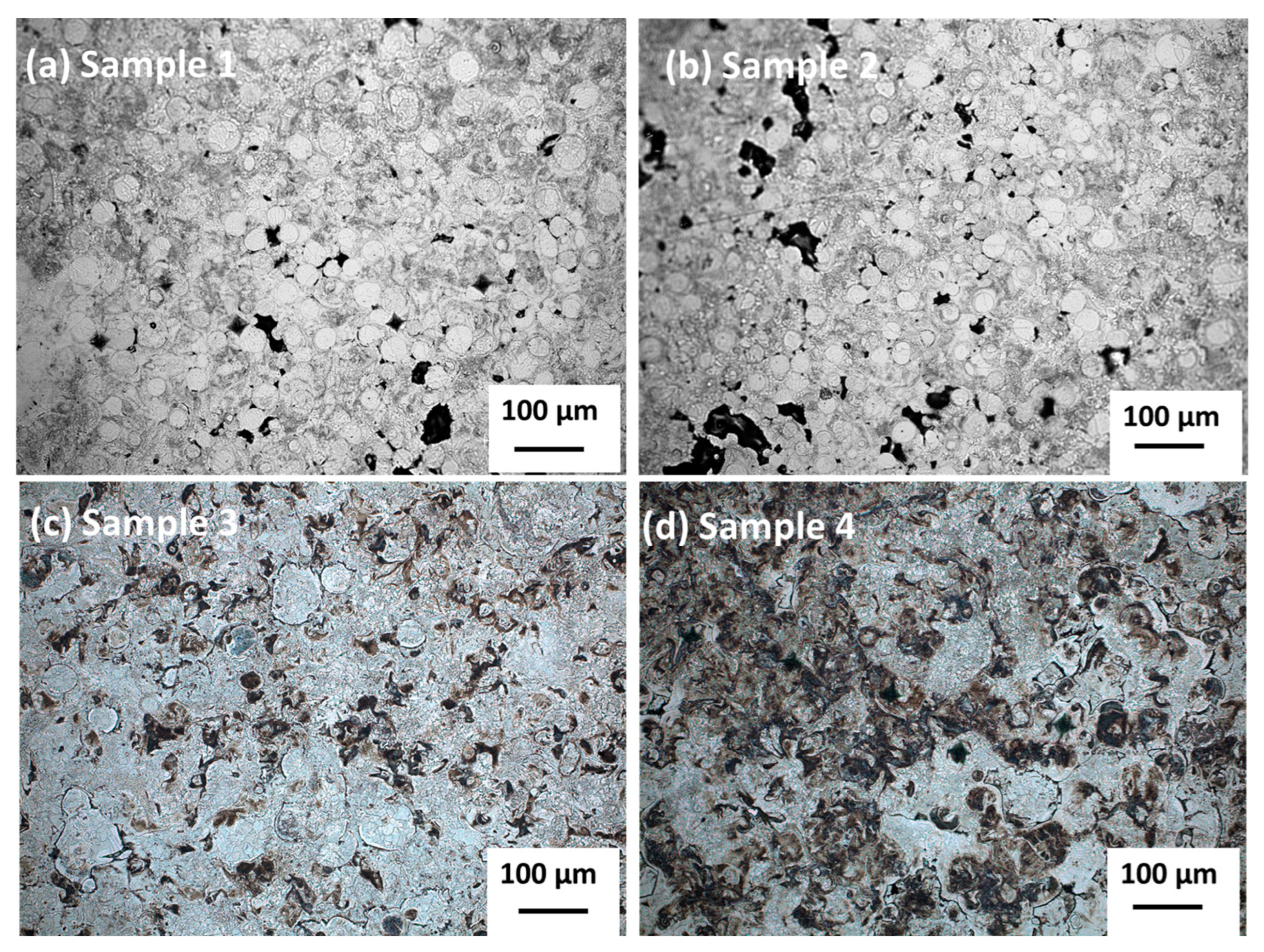
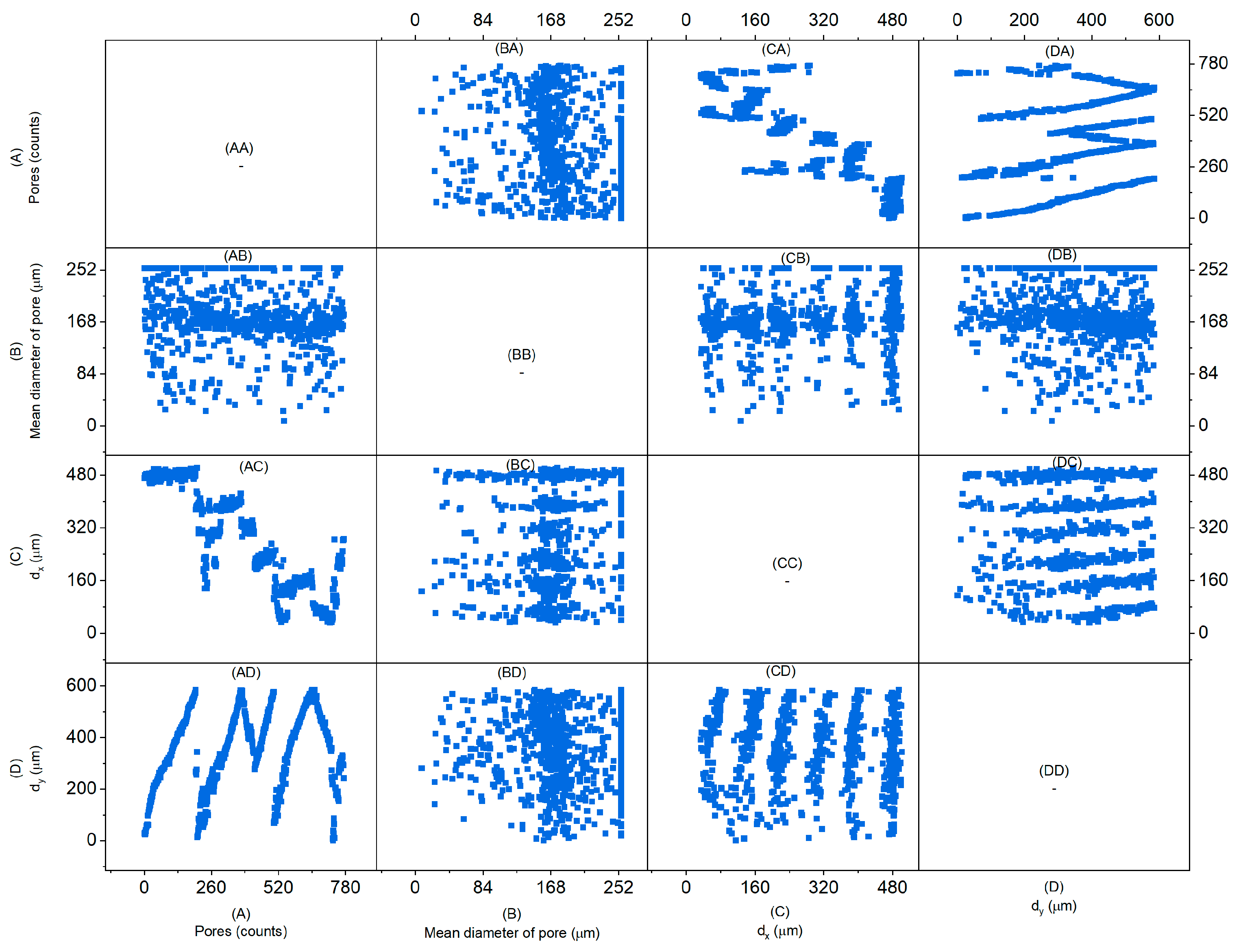
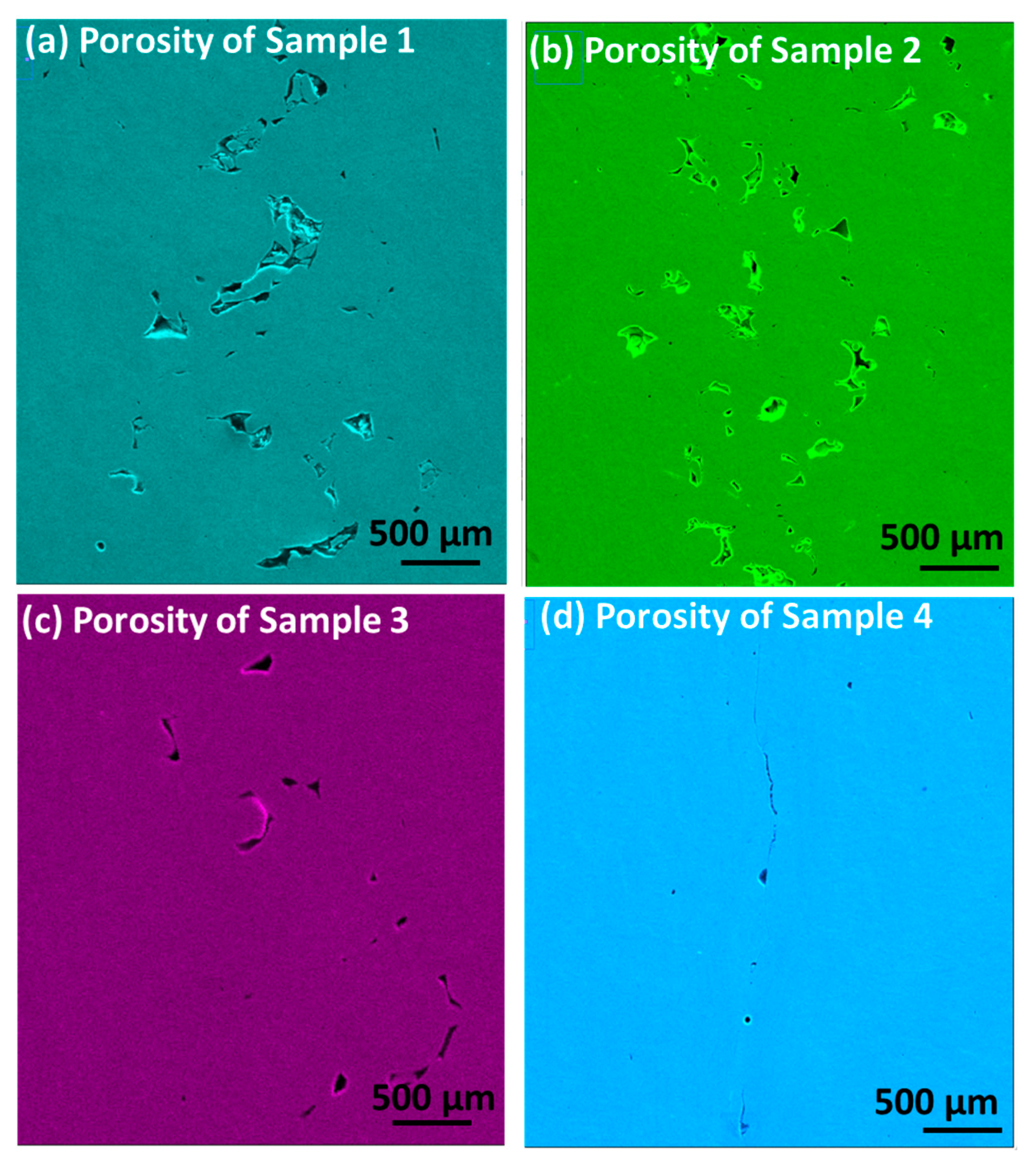
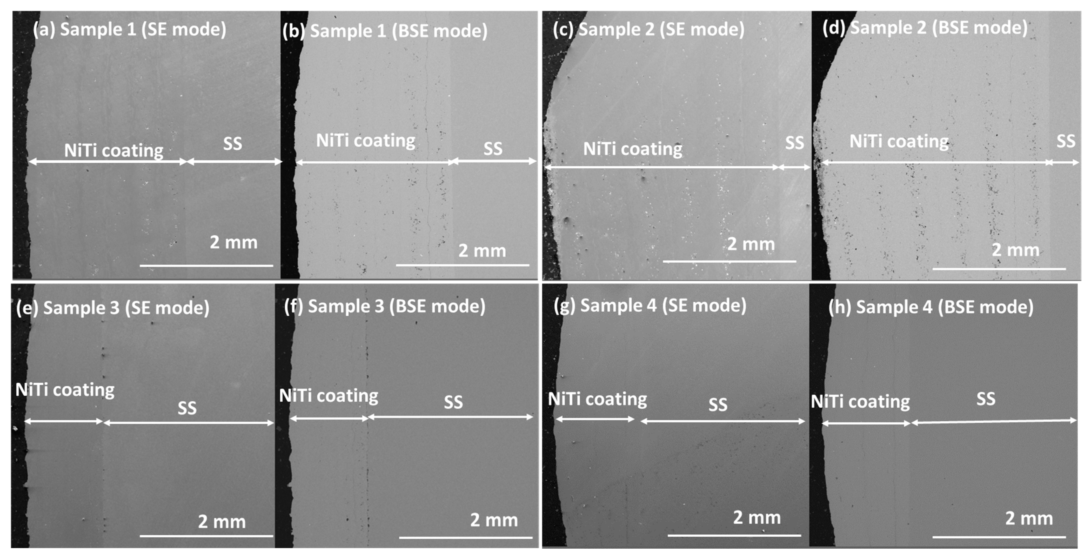
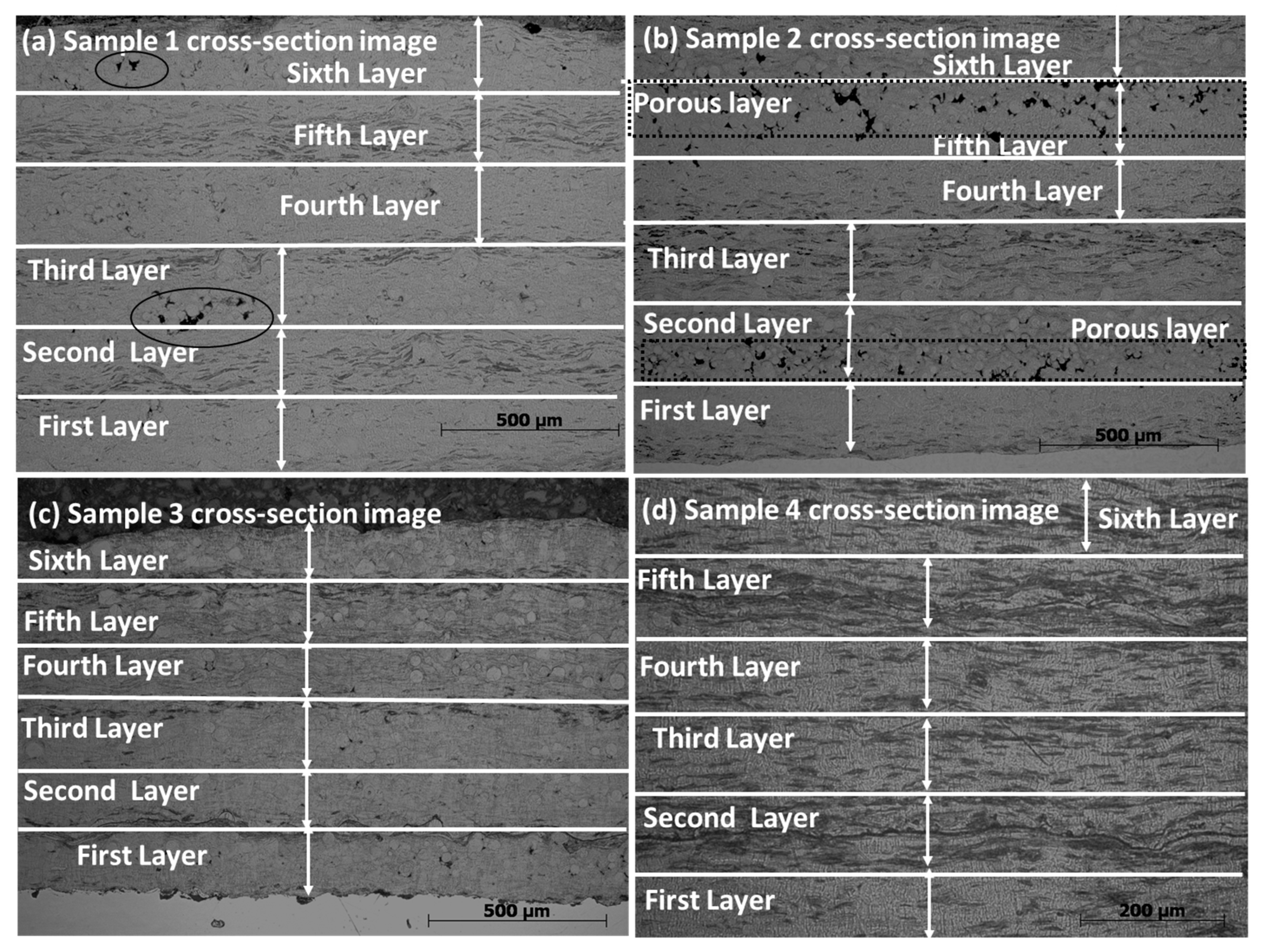
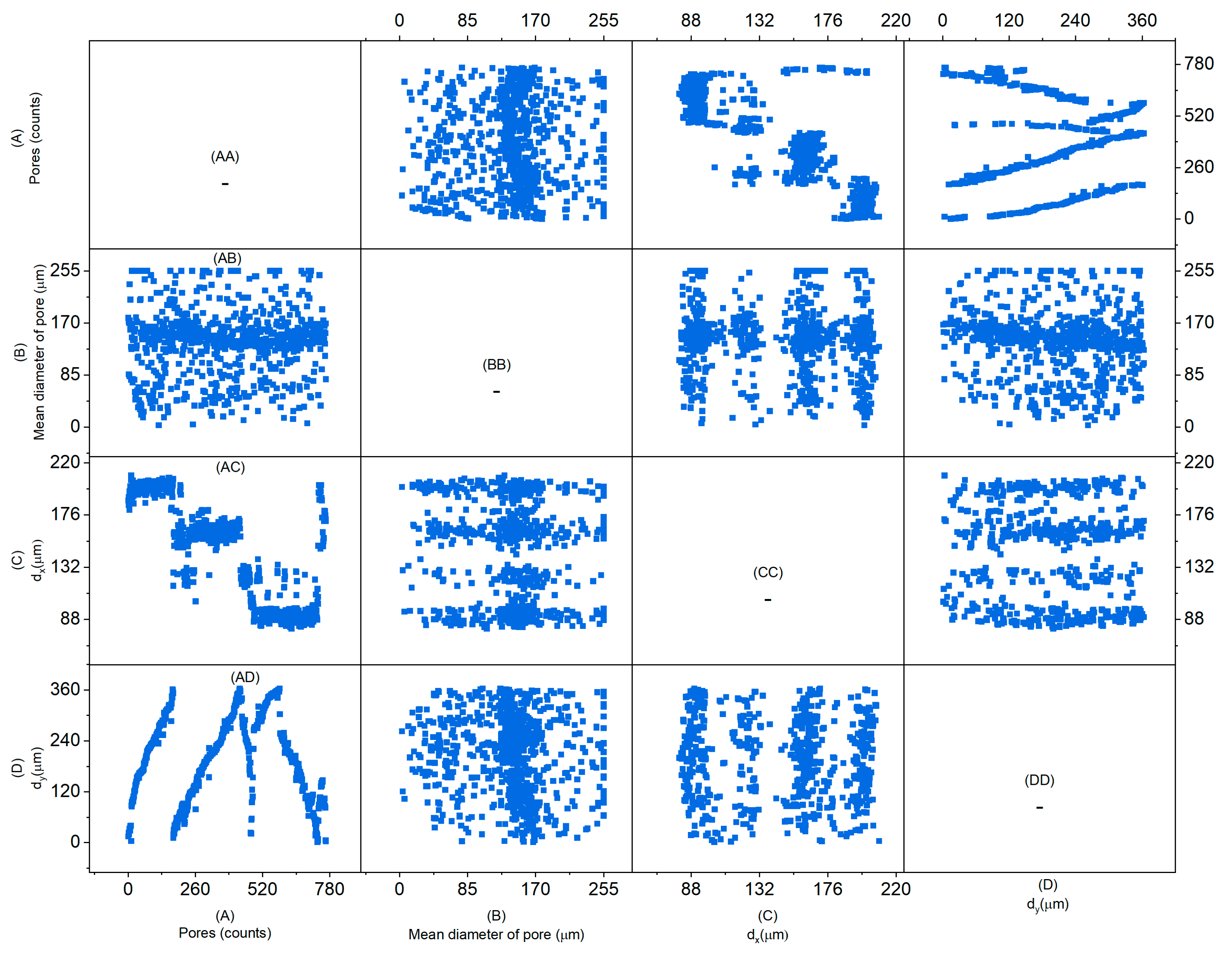
Microstructural Images of the Plasma-Sprayed Samples
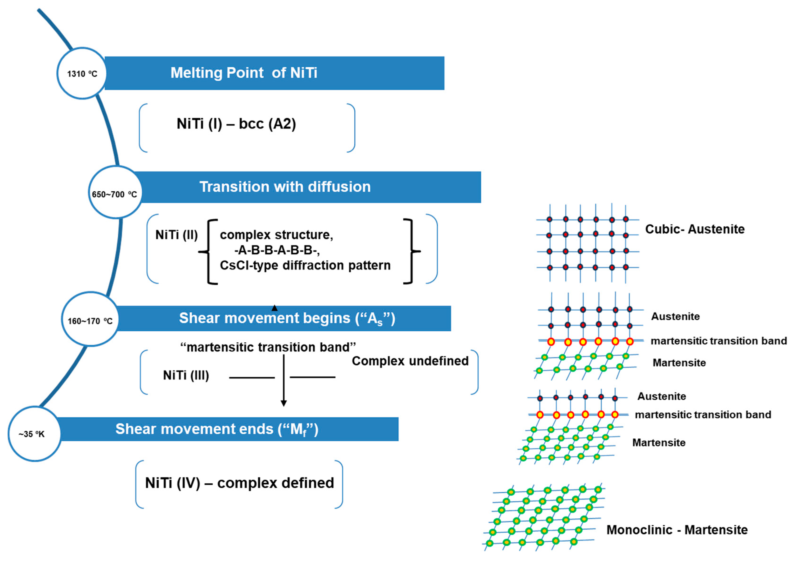
Figure 3a–d represent the surface image of the coating of the samples prepared at various experimental parameters. There is remarkable porosity in samples 1 and 2, which is marked as darker areas with black circular areas. However, sample 3 shows a fully molten splat throughout the surface with some porosity. The porosity is significantly minimized in sample 4 with a homogenized structure. To observe the coating layers, it is essential to investigate the thickness of the coating layers. Figure 4a–g show the cross-section of the samples with the substrate as the base in secondary electron (SE) and backscattered electron (BSE) mode. Both SE and BSE modes of imaging are chosen for the cross-section images of the coating to reveal more information about compactness, porosity, Ni-rich phases, or the presence of foreign elements. The porosity layers are visible in BSE mode of the coating layers along the cross-section in samples 1–2. However, sample 3 shows some minor porosity at the interface region. Sample 4 shows good-quality coating layers along the cross-section with a uniform microstructure. The more detailed analysis within the layers of the coating was investigated by using an optical microscope, as shown in Figure 5a–d. The samples were etched with an etchant to reveal the microstructure. It has been observed that sample 1 shows more porosity within the adjacent layers (first and second layers of coating) compared to the coating with substrate and the final layer of the coating (6th layer). This arrangement of porosity developments in the second and final layers (2th and 6th layers) of coating is observed in sample 2. This may happen due to unmelted splats that lead to voids at the interface of neighboring splats. This may occur due to particle flow in the outer layer of the plasma arc, where the temperature is lower, which leads to more unmelted splat. However, partially molten splats are visible throughout the thickness in samples 1–2. There is a possibility that other layers are more compact, with melted splat having less porosity. The porosity significantly decreases in samples 3–4. However, some partially molten splats are visible in sample 3 along the cross-section layers. Sample 4 shows a more homogeneous structure without any splat or porosity. However, more details of the porosity in coating layers were revealed by using ImageJ analysis, which measured quantitively the pore size within the coating layers. Figure 6 represents the scatter of the matrix of pores in sample 1. The matrix shows around 780 pores, with a mean diameter of pores of 255 µm, an elongated diameter of pores in the X-direction up to 220, and a maximum Y-axis diameter of 360 µm. The scatter matrix distribution shows various combinations of (A) the number of pores, (B) the pore’s mean diameter, (C) the diameter on the X-axis, and (D) the diameter on the Y-axis, with their various combinations in each square in the plot as (AA, AB, AC, AD), (BA, BB, BC, BD), (CA, CB, CC, CD), and (DA, DB, DC, DD) as vertical line distributions of pores in combination with respective values. Sample 2 shows the same number of pores, with a mean diameter of pores of 252 µm and a distribution of larger diameters of pores (Figure 7). The square of the distribution plots in the areas is confirmed from sections AB and DB. This shows a larger pore diameter in the range of 150 to 252 µm. There are fewer pores within the micro range of 0–85 µm. Figure 8 displays the scatter of pores within sample 3. There are very few larger pores. There are fewer pores in sample 3 (a total of 210) compared to samples 1 and 2. Average pores with a diameter of 85–170 µm are largely present within coating layers. The number of pores distributed within coating layers is well marked in section BC, which displays that pores are more likely in the top layers compared to other layers in the coating.
The mean diameter of pores within the range of 0–150 µm is well found in sample 4 (Figure 9). The pores are elongated in nature, as confirmed by the X- and Y-axis diameter measurements. Sample 4 confirms a smaller number of pores (213) with minimum sizes along the cross-section. There are interconnected pores along the cross-section lines that form cracks that may result from the mismatch of thermal expansion between the substrate and coating layers. The summary of pores as a function of pore size with counts and cumulative percent is presented in Figure 10a–d. It has been observed that samples 1 and 2 have more pores compared to samples 3 and 4. However, the larger pore distribution is more prominent in sample 2. Sample 3 shows various ranges of pores. Sample 4 has a limited range of pore distribution. The selected area with a zoomed-in view of elongated and spherical pores with interconnections making cracks is well visible in Figure 11a–d. The colors are chosen to highlight the visibility of pores.
The hardness of the plasma-sprayed samples was measured on both the surface and in cross-section areas at five different indent points. The results are evaluated and plotted in Figure 12 with the average and statistical distribution of the microhardness of the surface and cross-section for the samples. The porosity of sample 4 significantly decreases as a result of the high density of the compact structure of the sample. The hardness shows a lower value, which may correspond to various phases of NiTi present in the sample. If the martensite phase corresponds to the shape memory sample, it shows lower microhardness. The hardness with corresponding porosity may not be valid for shape memory alloys, as it corresponds to various phases of NiTi such as austenite and martensite. The hardness of NiTi falls in the range of 231.08 ± 17.23 HV, which corresponds to the value of sample 4 in the surface region. Other samples deviate from the standard value of hardness of NiTi, which may be due to porosity within the coating layers. The hardness of the NiTi coating is influenced by the various phases of NiTi, such as austenite, martensite, and intermetallic and oxide phases [33,34]. Figure 13 shows the XRD pattern of plasma-sprayed coatings with various phases of austenite, martensite, intermetallic, and oxide. The oxides phases are detected in samples 1–2, however, the intermetallic phases are found in samples 3–4.
Thermo-mechanical behavior of the plasma-sprayed samples is presented in Figure 14. Samples 1 and 4 are selected from the group as representative of coatings with and without porosity. The hysteresis behavior of both samples is observed as a function of thermal cycles from cooling to heating. However, sample 1 shows a non-uniform area of hysteresis with a narrowly distributed zone compared to sample 4.

4. Discussion

The plasma melting of powder results at 1310 °C, which corresponds to the NiTi melting point at a higher input power of 12 kW [34,35,36,37]. During the process of deposition of NiTi particles, the melted particles pass through the plasma arc and are deposited at the substrate surface with a zone of transition in the temperature range of 650~700 °C. During the temperature transition, various structures of NiTi are formed as a function of temperature. Figure 15 represents the dissociation of the NiTi phase from the melting temperature towards the deposition stage. The NiTi powder (50.at%) undergoes melting at 1310 °C, showing the formation of various phases from the ratio of Ni:Ti as a function of temperature, which is very well confirmed from the Ni-Ti phase diagram. The complex phase of NiTi is divided into various forms: simple, secondary, and ternary phases at various stages of processing and deposition temperature. The temperature induces the formation of the primary phase (1:1) towards the secondary phase of a combination of Ni and Ti (1:2) to form intermetallic compounds. The simplified NiTi phases of austenite and martensite (1:1) are confirmed with some phases of intermetallic compounds in the coating samples. There is the presence of an oxide phase in addition to other phases in the coating that may arise from the spraying process. Further, the formation of Ni2Ti4O results in the disproportionate removal of titanium from the alloy matrix.
Due to less power, NiTi powder may not reach the melting point, and as a result, the porosity is more prominent in samples 1 and 2. With the subsequent increase in plasma power to 12 kW, the target temperature of the melting point of NiTi reached led to compact coatings with less porosity. However, the residence time for melting particles to flow within the plasma arc may play a role in the partial porosity in samples 3 and 4.
However, phase formation during plasma spraying is controlled by the temperature range of particle impact with the substrate. The cooling temperature range may control the phase formation in the coating layers. The correlation of various phases of the NiTi alloy is pictured in Figure 15 and it shows the subsequent phases of the formation of NiTi alloys as a function of temperature.

5. Conclusions

The quality of NiTi coating layers generated during plasma spraying depends upon plasma input parameters such as plasma power (12 kW), feeding rate (2.1 g/min), stand-off distance, and substrate. The quality and compactness of the coating layers could be minimized by tuning suitable parameters for plasma spraying. However, the hardness of the coating layers is mostly based on the phase formation during spraying, such as the spraying temperature, which includes the melting temperature of NiTi particles and the temperature of splat at the surface of deposition. The temperature range of the sequence from molten particles with deposition of layers through the thickness to the final temperature (600–700 °C) determines the phase formation in the coatings. The phases were confirmed in the coating layers, and that contributed to the microhardness values. The thermo-mechanical behavior of the coating shows the hysteresis effect in bending mode, which reflects the shape memory effect.

Author Contributions

Conceptualization, S.S. and P.Š.; methodology, S.S., J.Z., J.K. and S.H.; formal analysis, S.S., O.P. and M.C.; investigationwriting—original draft preparation, writing—review and editing, S.S; funding acquisition, P.Š.; All authors have read and agreed to the published version of the manuscript.

Funding

This research was funded by the Czech Science Foundation (CSF) projects 22-20181 S (P.Š.) and the Project Solid-21 for the support within the Institute of Physics, Prague, Czech Republic (SOLID21: CZ.02.1.01/0.0/0.0/16_019/0000760, SOLID21-Fyzika Pevných Látek Pro 21. Století, Fyzikální Ústav AV ČR, v. v. i. (2018–2023)). CzechNanoLab project LM2023051 is funded by MEYS CR.

Data Availability Statement

Data will be available at the reader’s request.

Acknowledgments

The first author would like to acknowledge the Institute of Plasma Physics (IPP) of the Czech Academy of Science for the plasma facilities used to prepare samples.

Conflicts of Interest

The authors declare no conflict of interest.

References

  1. Richman, R.H.; Rao, A.S.; Hodgson, D.E. Cavitation erosion of two NiTi alloys. Wear 1992, 157, 401–407. [Google Scholar] [CrossRef]
  2. Richman, R.H.; Rao, A.S.; Kung, D. Cavitation erosion of NiTi explosively welded to steel. Wear 1995, 181–183, 80–85. [Google Scholar] [CrossRef]
  3. Bram, M.; Ahmad-Khanlou Buchkremer, H.P.; Stöver, D. Vaccum plasma spraying of NiTi protection layers. Mater. Lett. 2002, 57, 647–651. [Google Scholar] [CrossRef]
  4. Samal, S.; Zeman, J.; Kopeček, J.; Šittner, P. The Microstructure, Hardness, Phase Transformation and Mechanical Properties of a NiTi Coating Applied to Graphite Substrate via a Plasma Spraying Process. Coatings 2023, 13, 1174. [Google Scholar] [CrossRef]
  5. Samal, S.; Tyc, O.; Cizek, J.; Klecka, J.; Lukáč, F.; Molnárová, O.; de Prado, E.; Weiss, Z.; Kopeček, J.; Heller, L.; et al. Fabrication of Thermal Plasma Sprayed NiTi Coatings Possessing Functional Properties. Coatings 2021, 11, 610. [Google Scholar] [CrossRef]
  6. Swain, B.; Mallick, P.; Gupta Ram, K.; Mohapatra, S.S.; Yasin, G.; Nguyen, T.A.; Ajit, B. Mechanical and tribological properties evaluation of plasma-sprayed shape memory alloy coating. J. Alloys Compd. 2021, 863, 158599. [Google Scholar] [CrossRef]
  7. Zhao, Y.; Wen, J.; Peyraut, F.; Planche, M.-P.; Misra, S.; Lenoir, B.; Ilavsky, J.; Liao, H.; Montavon, G. Porous architecture and thermal properties of thermal barrier coatings deposited by suspension plasma spray. Surf. Coat. Technol. 2020, 386, 125462. [Google Scholar] [CrossRef]
  8. Samal, S. Thermal plasma processing of materials: High-temperature applications. In Reference Module in Materials Science and Materials Engineering; Elesvier: Amsterdam, The Netherlands, 2020. [Google Scholar]
  9. Özel, S.; Vural, E. The microstructure and hardness properties of plasma-sprayed Cr2O3/Al2O3 coatings. J. Optoelectron. Adv. Mater. 2016, 18, 1052–1056. [Google Scholar]
  10. Odhiambo, J.G.; Li, W.; Zhao, Y.; Li, C. Porosity and Its Significance in Plasma-Sprayed Coatings. Coatings 2019, 9, 460. [Google Scholar] [CrossRef]
  11. Ian, M.; Bernard, G.; Michael, B.; William, M.B.; Alyssa, C.; Kelvin, X.; Winson, K.; Winson, K.; Jonah, E. Self-Organized High-Hardness Thermal Spray Coatings. Available online: https://papers.ssrn.com/sol3/papers.cfm?abstract_id=3793930 (accessed on 27 October 2023).
  12. Zhang, Y.; Wang, Q.; Ramachandran, C.S.; Guo, P.; Wang, A. Microstructure and Performance of High-Velocity Oxygen-Fuel Coupled Physical Vapor Deposition (HVOF-PVD) Duplex Protective Coatings: A Review. Coatings 2022, 12, 1395. [Google Scholar] [CrossRef]
  13. Daroonparvar, M.; Azizi Mat Yajid, M.; Yusof, N.M.; Sakhawat Hussain, M. Improved thermally grown, oxide scale in air plasma-sprayed NiCrAlY/Nano-YSZ coatings. J. Nanomater. 2013, 2013, 520104. [Google Scholar] [CrossRef]
  14. Samal, S.; Kopeček, J.; Šittner, P. Interfacial Adhesion of Thick NiTi Coating on Substrate Stainless Steel. Materials 2022, 15, 8598. [Google Scholar] [CrossRef]
  15. Pilch, J.; Šittner, P. A Method of Heat Treatment and/or Inspection of Functional Mechanical Properties, Particularly Transformation Strain and/or Strength, of Shape Memory Alloy Wires and Apparatus for the Application of This Method. U.S. Patent 20120018413A1, 26 January 2012. [Google Scholar]
  16. Fauchais, P.; Vardelle, M.; Vardelle, A.; Bianchi, L. Plasma spray: Study of the coating generation. Ceram. Int. 1996, 22, 295–303. [Google Scholar] [CrossRef]
  17. Curry, N.; Leitner, M.; Körner, K. High-Porosity Thermal Barrier Coatings from High-Power Plasma Spray Equipment—Processing, Performance and Economics. Coatings 2020, 10, 957. [Google Scholar] [CrossRef]
  18. Gan, J.A.; Berndt, C.C. Effects of standoff distance on porosity, phase distribution and mechanical properties of plasma sprayed Nd–Fe–B coatings. Surf. Coat. Technol. 2013, 216, 127–138. [Google Scholar] [CrossRef]
  19. Samal, S. Study of porosity on titania slag obtained by conventional sintering and thermal plasma process. JOM 2016, 68, 3000–3005. [Google Scholar] [CrossRef]
  20. Wang, Y.; Adrien, J.; Normand, B. Porosity Characterization of Cold Sprayed Stainless Steel Coating Using Three-Dimensional X-ray Microtomography. Coatings 2018, 8, 326. [Google Scholar] [CrossRef]
  21. Zdravkov, B.; Čermák, J.; Šefara, M.; Janků, J. Pore clasification in the characterization of porous materials: A perspective. Cent. Eur. J. Commun. 2007, 5, 385–395. [Google Scholar] [CrossRef]
  22. Sobhanverdi, R.; Akbari, A. Porosity and microstructural features of plasma sprayed Yttria stabilized Zirconia thermal barrier coatings. Ceram. Int. 2015, 41, 14517–14528. [Google Scholar] [CrossRef]
  23. Gerald, O.J.; Wenge, L.; Tao, Z.Y.; Long, L.C.; Qiang, L. Influence of plasma spraying current on the microstructural characteristics and tribological behaviour of plasma sprayed Cr2O3 coating. Boletín de La Soc. Española de Cerámica y Vidr. 2021, 60, 338–346. [Google Scholar] [CrossRef]
  24. Vaßen, R.; Bakan, E.; Sebold, D.; Sohn, Y.J. Correlation of Process Conditions, Porosity Levels and crystallinity in Atmospherically Plasma Sprayed Yb2Si2O7 Environmental Barrier Coatings. J. Compos. Sci. 2021, 5, 198. [Google Scholar] [CrossRef]
  25. Amit, B.; Felix, E.; Balla, V.K.; Bose, S.; Ohgami, Y.; Davies, N.M. Influence of porosity on mechanical properties and In Vivo response of Ti6Al4V implants. Acta Biomater. 2010, 6, 1640–1648. [Google Scholar] [CrossRef]
  26. Oh, I.H.; Nomura, N.; Masahashi, N.; Hanada, S. Mechanical properties of porous titanium compacts prepared by powder sintering. Scr. Mater 2003, 49, 1197–1202. [Google Scholar] [CrossRef]
  27. Daure, J.L.; Voisey, K.T.; Shipway, P.H.; Stewart, D.A. The effect of coating architecture and defects on the corrosion behaviour of a PVD multilayer Inconel 625/Cr coating. Surf. Coat. Technol. 2017, 324, 403–412. [Google Scholar] [CrossRef]
  28. Holleck, H.; Lahres, M.; Woll, P. Multilayer coatings—Influence of fabrication parameters on constitution and properties. Surf. Coat. Technol. 1990, 41, 179–190. [Google Scholar] [CrossRef]
  29. Kabir, M.S.; Zhou, Z.; Xie, Z.; Munroe, P. Designing multilayer diamond like carbon coatings for improved mechanical properties. J. Mater. Sci. Technol. 2021, 65, 108–117. [Google Scholar] [CrossRef]
  30. Samal, S.; Sulovský, M.; Kopeček, J.; Šittner, P. Deposition and characterization of plasma sprayed NiTi powder on stainless steel and graphite substrate. Mater. Chem. Phys. 2023, 307, 128146. [Google Scholar] [CrossRef]
  31. Ali, R.; Sebastiani, M.; Bemporad, E. Influence of Ti–TiN multilayer PVD-coatings design on residual stresses and adhesion. Mater. Des. 2015, 75, 47–56. [Google Scholar] [CrossRef]
  32. Wang, Y.-W.; Sun, X.-W.; Wang, L.; Yang, Y.; Ren, X.-X.; Ma, Y.-D.; Cui, Y.-H.; Sun, W.-W.; Wang, X.-Y.; Dong, Y.-C. Microstructure and properties of CrB2-Cr3C2 composite coatings prepared by plasma spraying. Surf. Coat. Technol. 2021, 425, 127693. [Google Scholar] [CrossRef]
  33. Chicot, D.; Ageorges, H.; Voda, M.; Louis, G.; Dhia, M.A.; Palacio, C.C.; Kossman, A. Hardness of thermal sprayed coatings: Relevance of the scale of measurement. Surf. Coat. Technol. 2015, 268, 173–179. [Google Scholar] [CrossRef]
  34. Xu, H.; Jiri, N.; Bin, Z.; Ramirez, A.G. Nanoindentation of NiTi shape memory thin films at elevated temperatures. Int. J. Smart Nano Mater. 2011, 2, 39–49. [Google Scholar] [CrossRef]
  35. Buehler, W.; Wang, F. A summary of recent research on the nitinol alloys and their potential application in ocean engineering. Ocean. Eng. 1968, 1, 105–120. [Google Scholar] [CrossRef]
  36. Milan, H. Thermal Plasma Generators with Water Stabilized Arc. Open Plasma Phys. J. 2009, 2, 99–104. [Google Scholar]
  37. Davide, M.; Shimizu, Y.; Sasaki, T.; Koshizaki, N. Gas temperature and electron temperature measurements. J. Appl. Phys. 2007, 101, 013307. [Google Scholar] [CrossRef]
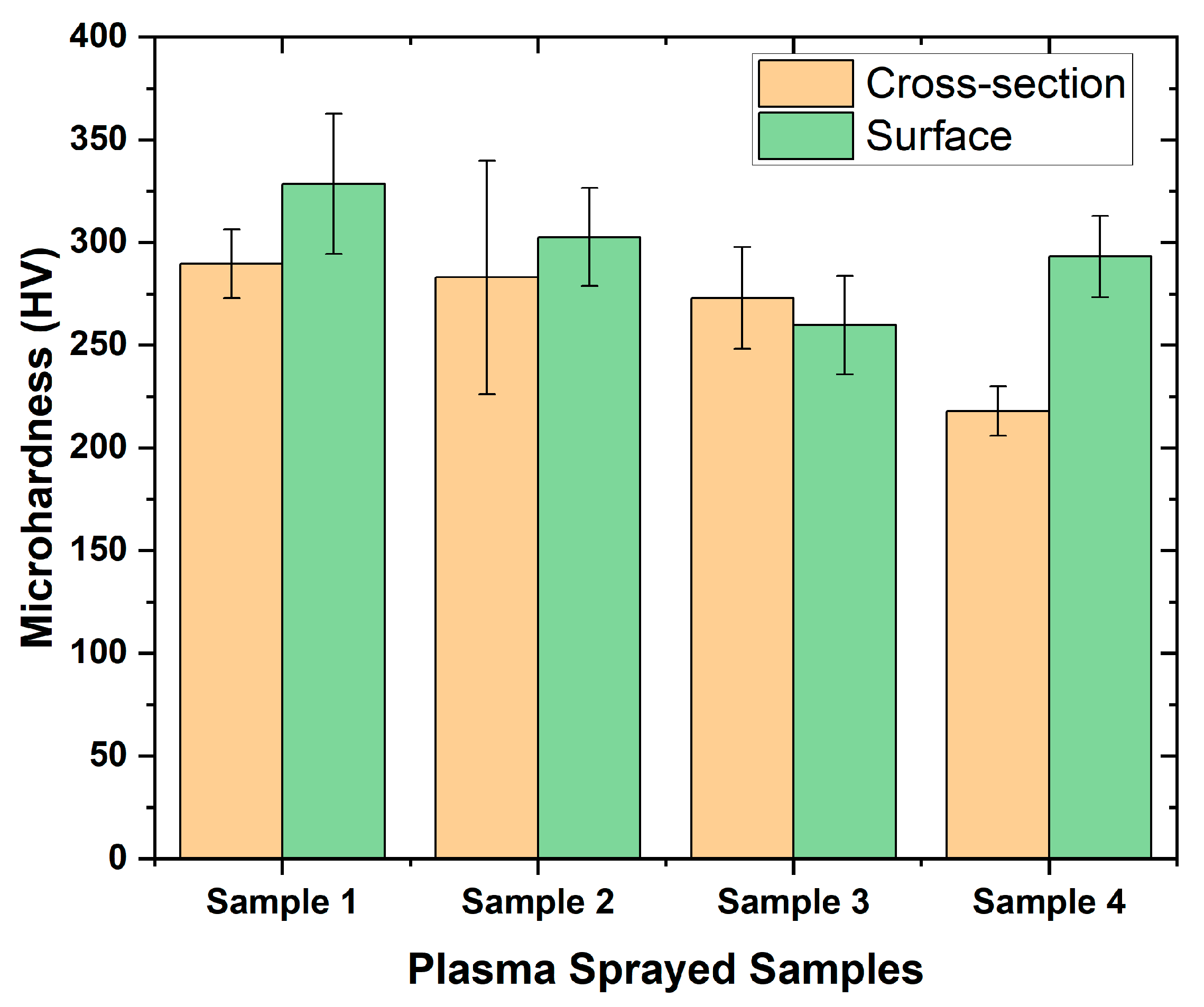
Figure 1. (a,b) Feedstock of NiTi powder; (b) Enlarged view of the NiTi particles; (c) EDX analysis of the red cross in (b) shows the inset element of Ni, Ti in Wt. %. With permission © 2022 by the authors. Licensee MDPI, Basel, Switzerland. This article is an open-access article distributed under the terms and conditions of the Creative Commons Attribution (CC BY) license (https://www.mdpi.com/1996-1944/15/23/8598 (accessed on 2 December 2022).) [14].
Jmmp 07 00198 g001
Figure 2. Impact of particles through a plasma arc for the deposition of coating layers on the substrate. With permission © 2022 by the authors. Licensee MDPI, Basel, Switzerland. This article is an open-access article distributed under the terms and conditions of the Creative Commons Attribution (CC BY) license (https://www.mdpi.com/1996-1944/15/23/8598 (accessed on 2 December 2022).) [14]. The spraying distance of 60 mm is chosen to cover the top surface area of the substrate with a scan speed of 1–2 mm/s.
Jmmp 07 00198 g002
Figure 3. (ad) Surface morphology of the samples 1–4 (plasma-sprayed coatings). The dark region (black areas) corresponds to the porosity on the surface of samples 1 and 2.
Jmmp 07 00198 g003
Figure 4. (ah) Cross-section of plasma-sprayed coatings 1–4 in SE and BSE mode shows the substrate stainless steel (SS) and NiTi coating layers (6 layers).
Jmmp 07 00198 g004
Figure 5. (ad) Details of the cross-section of plasma-sprayed coatings 1–4 in SE mode NiTi coating layers (6 layers).
Jmmp 07 00198 g005
Figure 6. Scatter matrix of pores in sample 1 (measurement of pore mean diameter, with diameters in X- and Y-directions).
Jmmp 07 00198 g006
Figure 7. Scatter of matrix of pores in sample 2 (A: number of pores; B: mean diameter; C and D: diameter of X- and Y-axes).
Jmmp 07 00198 g007
Figure 8. The scatter of voids in the matrix of mean, the diameter of particles in X- and Y-directions, various layers of sample 3 in cross-section areas.
Jmmp 07 00198 g008
Figure 9. The scatter of voids in the matrix of mean, the diameter of particles in X- and Y-directions, and various layers of sample 4 in cross-section areas.
Jmmp 07 00198 g009
Figure 10. (ad) Pore size distribution in plasma-sprayed samples 1–4. Fine, medium, and coarse microporosity is distributed in samples. Samples 3 and 4 avoid coarse pores that develop due to the accumulation or interconnection of medium pores in elongated ways.
Jmmp 07 00198 g010
Figure 11. (ad) Zoomed-in view of pores and interconnection in samples 1–4 shows the distribution of pores within the selected region.
Jmmp 07 00198 g011
Figure 12. Microhardness of surface and cross-section of the plasma-sprayed samples 1–4.
Jmmp 07 00198 g012
Figure 13. Phase identification for samples 1–4 by XRD pattern shows the austenite (B2), martensite (B19′), oxide, and intermetallic compounds.
Jmmp 07 00198 g013
Figure 14. Thermo-mechanical behavior of samples 1 and 4 shows the hysteresis behavior of the samples. (Two samples are chosen from more porous to less porous regions.)
Jmmp 07 00198 g014
Figure 15. Schematic diagram of the structural variations of stoichiometric NiTi (nominal 5 Nitinol) as a function of temperature. Redrawn from [35].
Jmmp 07 00198 g015
Table 1. Spraying parameters for coating of NiTi.
Sample NamePower (kW)Feeding Rate (g/min)Moving Speed (mm/s)Net Powder Spray Time (s)Microhardness in the Cross-Section of the Coating (HV)Microhardness on the Surface of the Coating (HV)
Sample 194.1230 × 6 = 180289.6328.6
Sample 294.1160 × 6 = 360283302.6
Sample 392.1225 × 6 = 150273259.8
Sample 4122.1225 × 6 = 150218293.2
(Substrate is stainless steel with central plasma gas argon + H2 (10 + 1), carrier gas Ar (8), preheat time 60 s).
Disclaimer/Publisher’s Note: The statements, opinions and data contained in all publications are solely those of the individual author(s) and contributor(s) and not of MDPI and/or the editor(s). MDPI and/or the editor(s) disclaim responsibility for any injury to people or property resulting from any ideas, methods, instructions or products referred to in the content.

