Article

Patterning of Surfaces for Subsequent Roll Bonding in a Low-Oxygen Environment Using Deformable Mesh Inlays

by
Yaroslav Frolov
1,2,
Oleksandr Bobukh
1,*,
Andrii Samsonenko
1 and
Florian Nürnberger
2
1
Metal Forming Department, Ukrainian State University of Science and Technologies, 49600 Dnipro, Ukraine
2
Institut für Werkstoffkunde (Materials Science), Leibniz Universität Hannover, 30167 Hannover, Germany
*
Author to whom correspondence should be addressed.
J. Manuf. Mater. Process. 2023, 7(5), 158; https://doi.org/10.3390/jmmp7050158
Submission received: 13 July 2023 / Revised: 2 August 2023 / Accepted: 10 August 2023 / Published: 2 September 2023

Abstract

:
Efficient roll bonding for the manufacturing of clad strips not only requires surface activation but also is improved by a surface patterning to reduce the initial contact area. This increases contact stresses and facilitates a joining without an increasing rolling force. Experiments to pattern surfaces with deformable inlays during cold rolling for a subsequent bonding in low-oxygen atmosphere were carried out using two types of rolling mills, two types of inlays and two types of assemblies. Digital twins of selected experiments were created by means of the FE simulation software QForm UK 10.2.4. The main set of rolling parameters, which play a significant role during formation of the pattern shape considering deformation of the patterning tool, were investigated. The pilot roll bonding of patterned components under vacuum conditions, provided using vacuum sealer bags, allowed for an experimental realization of this approach. The concept technological chain of roll bonding in a low-oxygen or oxygen-free environment comprises the following stages: roll patterning; surface activation and sealing of the strips in a vacuum bag; subsequent roll bonding of the prepared strips inside the protective bag. The difference between the shape of the pattern created and the initial shape of the mesh insert can be quantitatively described by the change of its angle. This difference reaches maximum values when smaller rolls are used with increased rolling reductions. This maximum value is limited by the springback of the deformed insert; the limit is reached more easily if the inlay is not positioned on the rolling plane.

1. Introduction

Roll bonding of similar or dissimilar metallic materials is an established manufacturing process. In [1], key process parameters were reviewed and a comprehensive discussion provided on the scientific and technical aspects that affect the microstructure and the mechanical behavior of the joint. Additionally, well-evaluated advantages and shortcomings of roll bonding applied to pairs of materials depending on the type of their crystal lattice were addressed. In this context, the following parameters which might accelerate the bonding should be highlighted:
Temperature: Temperature increases the kinetic energy of atom oscillations and expands the activity of the electron cloud [2]. According to the Arrhenius formula, the temperature increases the probability of forming metallic bonds between closely compressed surfaces [3]. The source of elevated temperatures is not only a pre-heating but also deformation heat as well as the heat induced by friction. The authors of [4] concluded that the temperature in combination with applied compression leads to plastic deformation in the soft component.
Rolling reduction: Due to rolling reduction, a transition of both surfaces into a ductile state according to their strain–stress behavior occurs. The main phenomenon here is the appearance of juvenile inner atomic layers from both surfaces. These arise due to the inhomogeneity of the metal flow [5] and move with the corresponding velocity along the rolling direction, which depends on the strain. The vertical flow, which is directed from both outer surfaces to the rolling plane, depends on the roll’s diameter [6]. This vertical component of the metal flow contributes to formation of the juvenile layers and to establishing the bonding. Due to the geometry of the deformation zone, especially its length [7], the smaller the diameter of rolls, the higher the vertical velocity mentioned above. The combined vertical and axial flow velocities are related to the strain rate.
Strain rate: According to the kinetic energy formula, elevation of the velocity with which particles move multiplies the collision energy and, consequently, the temperature effect [8]. Regarding [7], it is possible to observe the contradiction between the evaluation of the effect of the strain rate on the bonding efficiency: lower roll diameters increase the strain rate, which might increase the bonding strength. On the other hand, at elevated temperatures, greater roll diameters provide an increased time for diffusion under pressure.
Surface: Jamaati and Toroghinejad [9] concluded that the surface roughness increases the bond strength. They linked this to an increase in rolling force and pressure, as well as work hardening. From other hand, according to experiments reported by Xiangyu [10], polishing helps bring the surfaces to be bonded as close as possible before rolling. This, combined with localized strain inhomogeneities, increases the surface interaction. This is especially important for cold roll bonding. Alternatively, brushing can be applied to increase the roughness and thus to increase mechanical interlocking and the surface area as shown in [9]. Another effect activated by brushing is the formation of highly deformed and thus work-hardened surface layers, which break down during the roll bonding and thus promote the formation of new oxide-free, juvenile surfaces suitable for diffusion bonding [11]. A relative novel method of laser surface modification with extremely high energy densities was shown to activate the surface layers with identical or similar microstructures and properties [12]. The discussion of the interface conditions opens up a wide range of effects, which can be classified as harmful, conditionally helpful and helpful. Surfaces to be bonded are usually covered with a layer of surface contaminants, such as organic remains, inorganic compounds, oxides, and adsorbed moisture. These inhibit bonding, especially at room temperature. Consequently, the surface preparation, which includes proper cleaning and at least partially removing the surface layer, is a very important factor affecting the bond strength [9]. One example of a conditionally helpful effect is the so-called “zip bonding” effect [13], in which an aluminum matrix metal encloses steel wires due to their consistent ovalization and twisting. This provides an inherent “mechanical” bond strength even with a rolling reduction of approximately 25%. Such an approach does not in itself provide any sufficient bond but allows the fixing of the joint while diffusion takes place during the subsequent heat treatment. Another example is the application of such a material inlay to localize strain and provide temporary bonding. Helpful inlays are various reinforcements with expanded meshes [14]. Such types of inlays provide both a mechanical bonding of the matrix at low rolling reduction, which allows the application of a double-pass rolling and improves the mechanical properties of the finished composite. Due to its manufacturing method, the expanded mesh is an example of the application of the so-called “kirigami technique”, which allows for reaching elevated elongations with a predicted change in the cell shape [15]. Usage of a kirigami-inspired approach is a promising engineering method for creating out-of-plane structures [16], or strain-insensitive components, for example, electrodes [17].
The objective of this work is to investigate the possibility of using a deformable steel mesh inlay as a patterning tool for aluminum and copper surfaces that are subsequently roll bonded. The patterning is assumed to facilitate the bonding by increasing the contact stress and avoiding an elevation of the rolling force. Mechanical profiling of surfaces to be bonded is usually carried out by brushing or grinding [18]. This is mainly designed to remove oxides. Creating a pattern by deformation with profile dimensions of 0.1 to 1 mm on the surfaces to be bonded is not a trivial task. Challenges include localized work hardening, an increase in the oxidized surface area, a need for special rolls and the generation of thickness inhomogeneities. However, applying an oxygen-free environment [19] during the roll bonding removes one of these obstacles, and the use of a steel mesh [20] as a patterning tool between the surfaces to be subsequently bonded removes another. Here, quantitative data about the distortion of the mesh geometry under tensile stress in the deformation zone are of particular interest in understanding the behavior of the inlay in the rolling plane.

2. Materials and Methods

The experimental procedure to investigate the mesh distortion consisted of the following steps:
Samples for patterning (matrices). Materials used for the experiments with chemical compositions according to the corresponding standards were aluminum (EN AW 1050) and copper (ASTM B370) in fully annealed condition with the dimensions (h × b × l) 1 mm × 10 mm × 100 mm.
Patterning inlay. Two types of mesh made of Cr-Ni steel 1.4301 were used to apply the pattern to the matrix surfaces (Figure 1):
  • expanded mesh with cell dimensions 4 mm × 2.2 mm × 0.5 mm, the thickness of the sheet from which the mesh is made (Figure 1a) is 0.5 mm;
  • wire mesh with cell dimensions of 0.63 mm × 0.63 mm × 0.25 mm, where 0.25 mm is the diameter of the wire (Figure 1b).
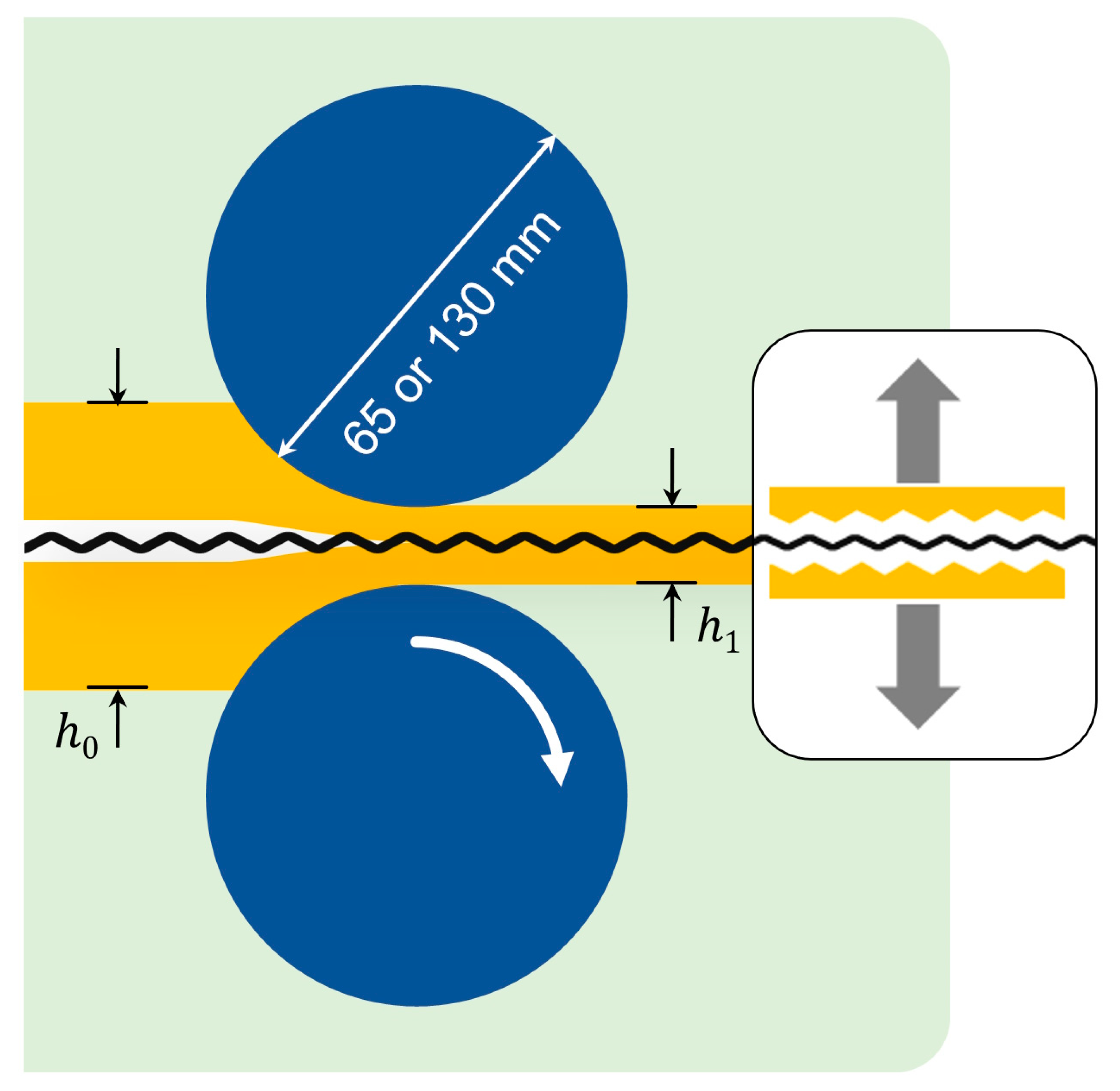
So-called sandwiches, consisting of alternating layers of matrix and netting insert, were assembled and secured prior to rolling. The netting cells of both types of netting were oriented diagonally to the rolling direction RD (see Figure 1). Patterning of the matrices was carried out by rolling at room temperature using two types of rolling mills: with 65 mm diameter rolls (type A) and with 130 mm diameter rolls (type B). Axial speed along the rolling plane was 0.02 m/min for both mills. A schematic of the experimental roll patterning of the matrix interface with the mesh inlays is depicted in Figure 2.
Two rolling reductions were applied during the experiments:
  • First, the rolling gap, which determines the final thickness of the outgoing strip (h1), was set at 85% of the initial thickness of the assembly (h0), which corresponds to a rolling reduction of 15%. These experiments were indexed with single-digit numbers.
  • The second approach implied that the rolling gap is equal to the sum of the initial thicknesses of the assemblies. These are denoted by two-digit numbers.
For example, experiment A3 was carried out using a rolling mill with a roll diameter of 65 mm and a rolling gap of 85% of the initial thickness of the assembly. Experiment code B30 means rolls with a diameter of 130 mm and a final thickness equal to the sum of the initial thicknesses of the assemblies. A visualization of the experimental assemblies is depicted in Figure 3.
The special feature of this series of experiments is the use of two types of rolling mills to determine not only the effect of the rolling reduction but also the separate effect of the length of the deformation zone.
Taking this into account, parameter values characterizing each experiment according to the following equations were calculated.
Absolute reduction:
Δ h = h 1 h 0 ,
where (h0) and (h1) are the initial and final thickness of the assembly, respectively (see Figure 2).
Rolling reduction:
ε = Δ h h 0 × 100 %
and length of deformation zone:
L D = R Δ h ,
where R denotes the rolls’ radii.
The form factor of the deformation zone is as follows:
F = L D / h 0 + h 1 2 .
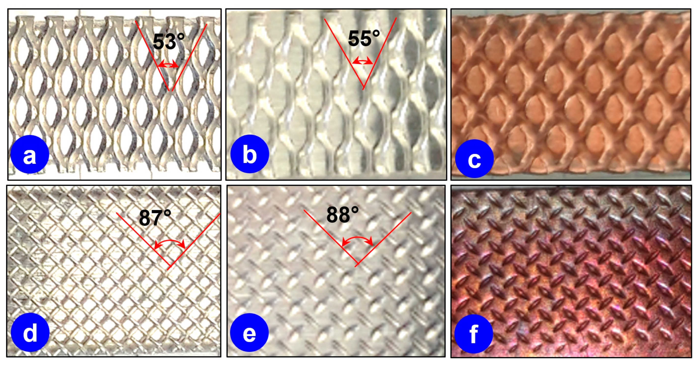
The distortion of the steel mesh inlay was evaluated as the difference between the initial angle of the mesh cell and its residual angle imprinted on the matrix (Figure 4).
This approach allows one to compare the effect of roll reduction and the influence of roll diameter on the distortion of the netting inlay. The distortion angle values were calculated as
α 1 0 = α 1 α 0 ,
where α 0 is an initial angle of netting cell and α 1 the measured angle of the imprint according to Figure 4.
Another parameter that affects the behavior of the inlay and consequently the shape of the pattern is the displacement of the steel-mesh inlay from the rolling plane. Experiments with A l 1 + N exp   o r   w i r e + C u 1 + N exp   o r   w i r e + A l 1 assemblies allowed us to evaluate how the mesh geometry would change if located between the rolling plane and the surface of the rolls.
Numerical simulations of the process of aluminum matrix patterning with an expanded mesh during rolling were performed for conditions corresponding to the experiments. The commercial FE software QForm UK [21] was used to create a digital twin of the cold patterning process and to predict the surface profile of the matrix. This software shows a good applicability for the digital twinning of complex metal forming processes. In a recent study [7], the simulation procedure has been described in detail. The metal properties of the aluminum (EN AW 1050), copper and the Cr-Ni steel 1.4301 were taken from the software database according to the material designation.
QForm UK is the commercial software designed for FE mathematical modeling of metal forming processes considering thermomechanical tasks, including the interaction of deformable workpiece with technological tools and equipment. The mathematical basis of the program is a system of equations, which includes the equation of equilibrium, the equation of the relationship between the field of velocities of material points and strain rates, the equation of the relationship between stress and strain, compression conditions, plasticity and energy balance equation. The geometry of rolling rolls, half-matrices and the mesh was drawn using CAD system before the simulation. The special subprogram of QForm UK software was applied for discretization of geometrical models using tetrahedron finite elements with minimal dimensions: half-matrix—0.1 mm; the mesh—0.05 mm; rolls 0.3 mm.
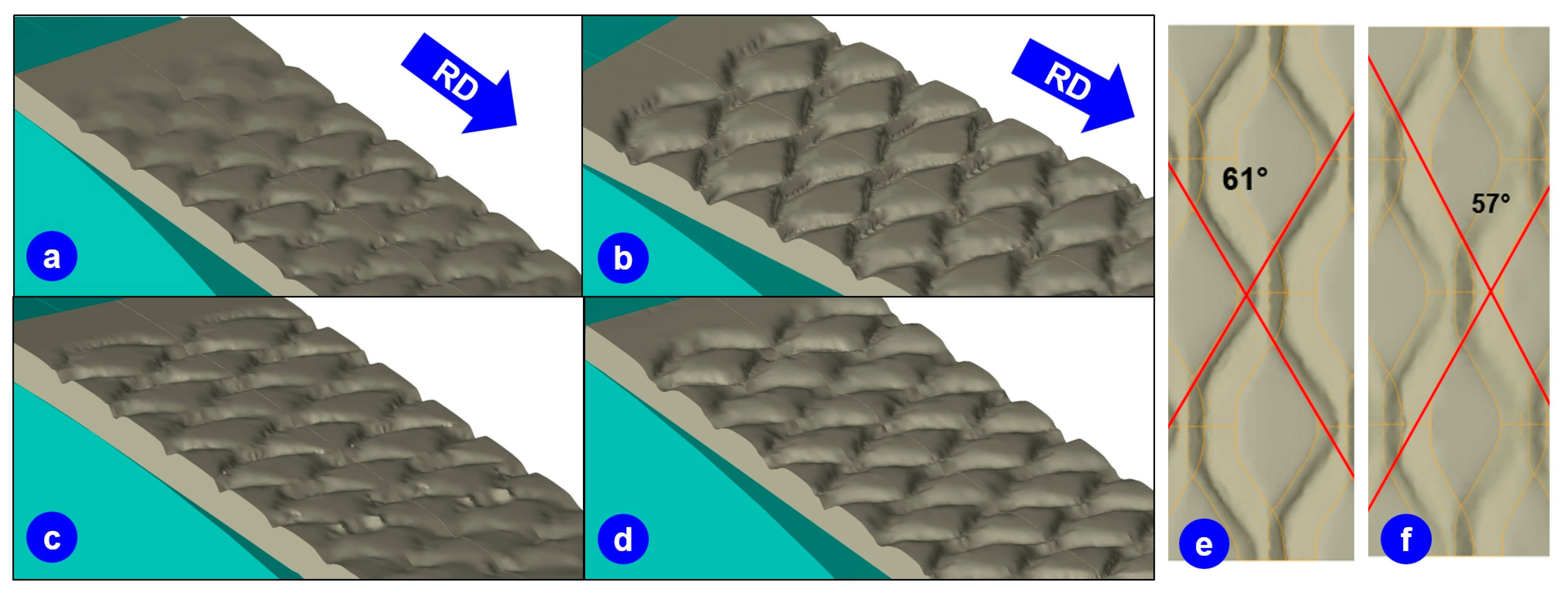
The exemplary visualization of resulting matrices is shown in Figure 5. Here, the simulations were carried out for conditions according to the experiments A1–A10 as well as B1–B10, where the mesh insert was placed on the rolling plane, to gain comparative data on the distortion angle. Such a digital twin of the process opens up future possibilities for a detailed 3D analysis of the obtained patterns.

3. Results

Values of the distortion angle α 1 0 are depicted in Figure 6 as a function of form factor F for experiments to pattern aluminum matrices A l 1 + N e x p + A l 1 and A l 1 + N w i r e + A l 1 (see Figure 3) using mills with different diameters of rolls as well as two types of netting inlays.
The comparison of the experimental and numerical values of the distortion angle shows that there is a certain deviation. It would be interesting to investigate the source of this deviation in detail in further studies. According to the experience of the authors, the deviation is probably related to the applied friction laws as well as to the behavior of the metal at the elastic–plastic transition. In the case of smaller rolls (experiments A1–A10), the predicted value of α ( 1 0 ) according to Equation (5) was one degree higher for both high and low form factors F according to Equation (4). The deviation of the predicted values of the distortion angles for experiments with larger rolls (B1–B10) disappears with the increase in F , which in this case means an increase in the roll reduction.
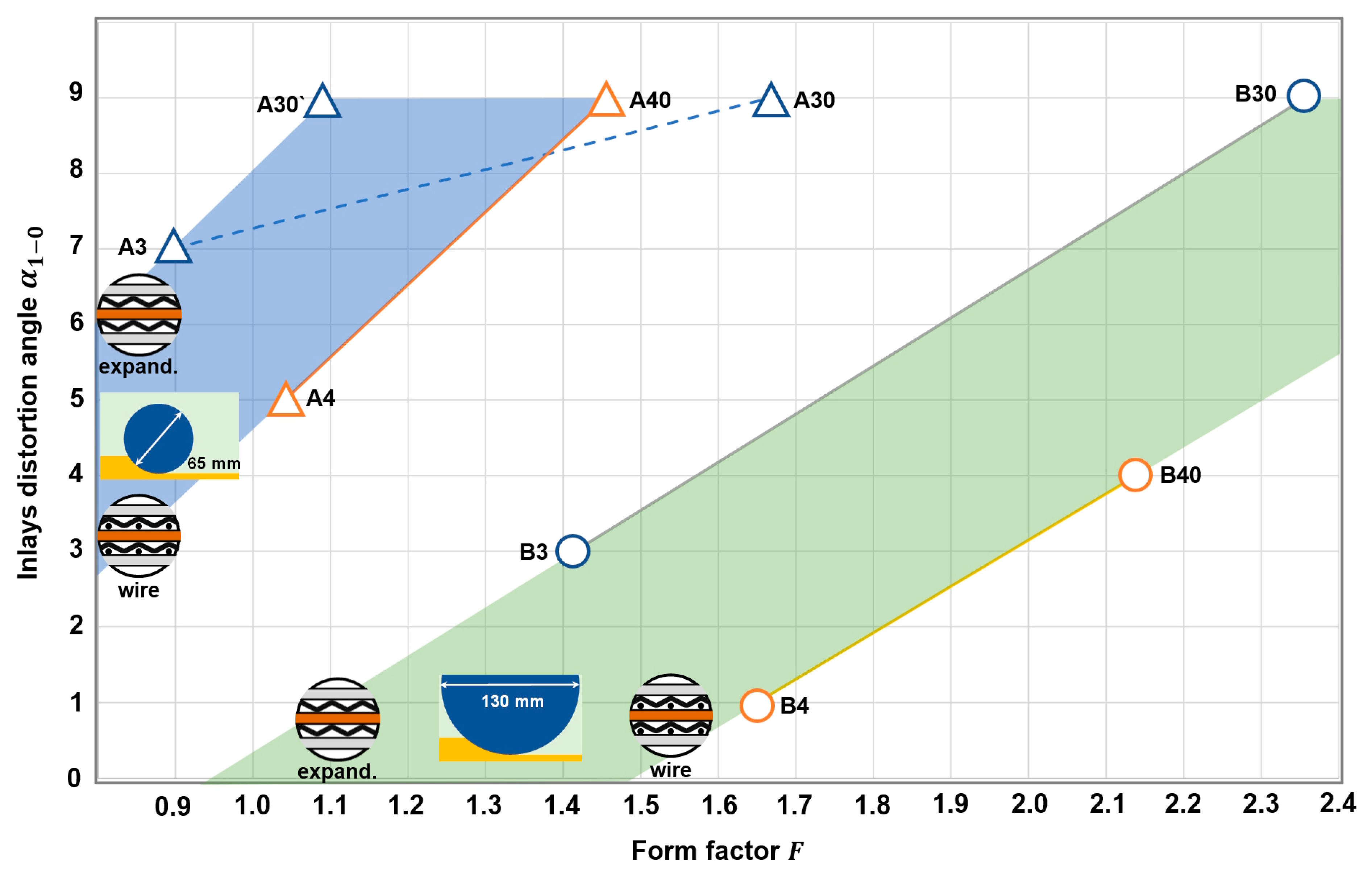
The effect of form factor F during roll patterning of the assemblies A l 1 + N e x p + C u 1 + N e x p + A l 1 and A l 1 + N w i r e + C u 1 + N w i r e + A l 1 (see Figure 3) in mills with various diameters of rolls is depicted in Figure 7. Additional rolling with a lower reduction was performed to verify that the growth of the distortion angle maintains its proportionality to the form factor when its values are less than 1.1 (additional point A30’).
During the experiments it was observed that the distortion angle of the expanded mesh demonstrates the ability to distort up to 9 degrees. Beyond this threshold value, the mesh is fractured due to clamping between the matrices.

4. Discussion

According to the results of the geometric change of the netting inlay during roll patterning of both aluminum and Al-Cu-Al matrices, it should be noted that this effect can be assumed to be linear, which allows it to be described with equations of the following types:
α 1 0 = k 1 F b 1
or
α 1 0 = k 2 ε b 2 ,
where k 1 is the proportionality factor in Equation (6), which indicates the intensity of distortion-angle change or how many degrees of the distortion angle α 1 0 is added per unit of form factor F ;   k 2 in Equation (7) describes the relationship between the distortion angle and the percentage of rolling reduction ε ; b is the so-called delay factor which indicates the threshold of sensitivity of the netting to distortion as a function of form factor F (regarding b 1 ) or rolling reduction ε (regarding b 2 ) . The values of the coefficients in Equations (6) and (7) are given in Table 1:
The values of coefficient k 1 from Table 1 reveal that the intensity of the change in angle is almost independent of the netting type for the same type of assembly A l 1 + N + A l 1 as well as of A l 1 + N + C u 1 + N + A l 1 . The variation range is ± 0.1…0.2, which equals 1…2%.
Regarding the dependence related to the rolling reduction according to Equation (7), it can be observed that each percent of rolling reduction provides a certain change in distortion angle. The independence of the distortion angle on the type of netting, according to the values of coefficient k 2 , is retained only for rolling of the assemblies A l 1 + N + A l 1 in larger rolls (experiments B1–10 and B2–20). The ranking of the experimental parameters in degrees per percent of the rolling reduction is presented in Table 2.
Usage of the form factor to understand how rolling parameters affect the delay factor is quite inconvenient. It is more helpful to analyze the values of the coefficient b 2 , which indicate how much percent of rolling reduction has to be applied under certain conditions to initiate a distortion of the netting. The ranking of the parameters that contribute to the deformation of the mesh geometry is shown in Table 3.
Negative values of the coefficient b 2 reveal how small rolls and how displacements of the inlay from the rolling plane cause the mesh geometry to move even before the plastic deformation of the entire assembly begins.
An analysis of both rankings (Table 2 and Table 3) allows one to characterize the following rolling parameters from the point of view of their influence on the distortion of the mesh during the rolling pattern:
  • Distortion of the mesh is proportional to the rolling reduction in the range of 9% to 28% until reaching 9 degrees;
  • The smaller the diameter of rolls, the higher the ability to distort for both types of netting; the expanded mesh shows slightly higher intensity and lower threshold of distortion (positions 1 to 3 in Table 1 and 1 to 2 in Table 2);
  • Displacement of the inlay from the rolling plane plays a significant role in lowering the distortion threshold but also results in a lower distortion intensity (positions 1 to 3 in Table 2 and 6 to 8 in Table 1).
The qualitative visualization of the common influence of the investigated parameters on the distortion of the mesh inlay is presented in Figure 8.

5. Application of the Obtained Results in Oxygen-Free Production

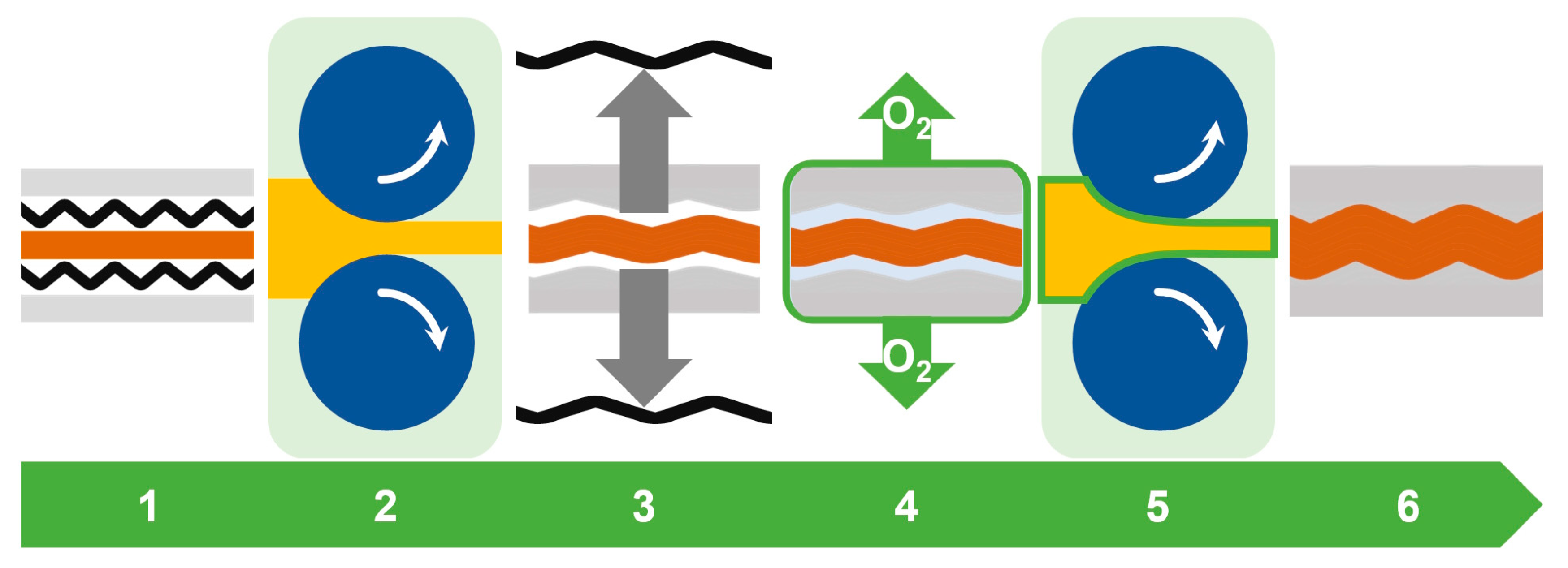
According to the concept of “oxygen-free production”, the oxygen content is to be reduced to extremely low levels [22]. In such an oxygen-free environment, completely new energy-efficient and resource-conserving processes and overall production efficiencies can be realized since new oxide layers do not form on newly created surfaces [23]. Hence, one approach to facilitate an enhanced bonding of two metallic surfaces is isolating these surfaces from oxidizing atmosphere. Here, polyethylene (PE) sealer bags were used to create an evacuated atmosphere around the assemblies. This means that during the subsequent roll bonding, the rolls do not come into contact with the outer metallic layer of the matrix but with a thin PE film. Therefore, this process is called “bag rolling”. Such an approach does not allow for the application of elevated temperatures and/or intense rolling reductions to achieve bonding in a single rolling pass. The patterning of the contact surfaces described above was aimed at increasing the contact stress at the bonding surfaces without significant increase in rolling force. Thus, it can be used as one of the process steps within the roll bonding technology chain depicted in Figure 9.
The functionality of such a process chain was tested using the following elements:
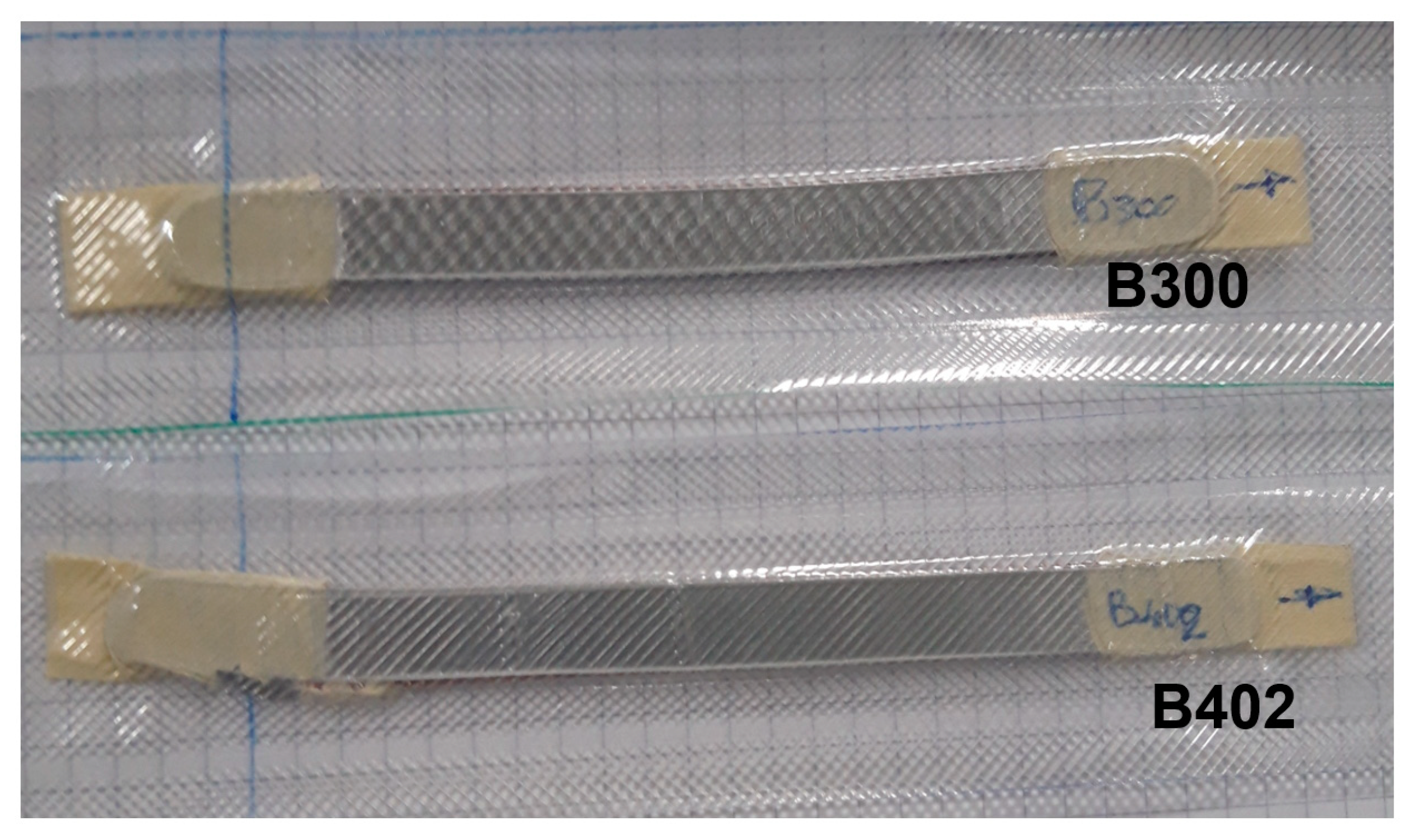
  • Assemblies were previously patterned using 130 mm diameter rollers with both expanded mesh (B300) and wire mesh (B402);
  • Low-oxygen partial-pressure atmosphere was provided by vacuuming in a PE sealer bag;
  • Roll bonding at room temperature using three passes with approximately 10% rolling reduction during each pass until 33% of accumulated reduction was reached (Figure 10) without any additional surface treatment;
  • Control of the integrity of the insulating bag was performed after each pass using a water bath;
  • Roll-bonded composites were tested regarding a primary bonding (mechanical joining) after removal of the bag.
Due to the reliability of the sealing bag, the reduction in single-pass rolling was limited to 10%. The corresponding low strain is not sufficient to achieve a bonding. Here, obtaining a bonding, which is not lost after post-rolling operations such as removing the sealer bag, straightening and cutting, was evaluated as a positive result. Figure 11 shows patterned and non-patterned samples roll bonded under identical conditions in the sealing bag after its removal. It can be observed that the patterned samples remain joined after such post-rolling functional operations in contrast to the non-patterned specimen.
The surface of the specimen holding the bond from Figure 11 was patterned according to experiment B10 (cf. Figure 5 and Figure 6) with the value of the distortion angle of 7 degrees.
The functional test showed that the use of patterned components enclosed in PE sealer bags after vacuuming seems to be a promising approach for oxygen-free cold roll bonding. For further development, the following features should be considered:
  • The strain hardening of components during patterning differs from non-patterned specimens;
  • Good results can be obtained if the inner component (here: copper) features a slightly higher yield stress and sufficient elongation capabilities;
  • Roll bonding in insulating sealer bags requires smooth surfaces of the assemblies;
  • The thickness of the insulating film does not decrease significantly in the deformation zone; failure is more likely to occur due to inhomogeneity of stress and/or surface inaccuracies;
  • Friction between rolls and film must be less than between rolls and composite, but this impairs the grip in the deformation zone;
  • Use of larger rollers in comparison with smaller ones provides longer life of the insulation bag;
  • Alignment and guidance of the packed assembly when rolling is important to prevent a bending of the rear end during rolling.

6. Conclusions

  • The use of form factor F to describe the experimental results obtained during roll patterning with various roll diameters and roll reductions allows one to observe the common effect of these parameters on the distortion of the netting inlay made of two different types of meshes. The numerical simulation of the process using the FE software QForm UK is in accordance with the obtained experimental values of the inlay distortion angle for F > 1.5. For lower values, it is observed that the predicted angle is one degree higher than the experimental value.
  • Mesh angle distortion increases proportionally with the increase in rolling reduction for 0.33–0.68 degrees for each percent of strain until it reaches 9%. Further deformation of the inlay results in its fracturing due to clamping of the mesh between the matrices. The highest intensity of distortion is observed during rolling with smaller rolls.
  • The use of rolls with half the diameter is the second important factor, which increases the net distortion angle by about 30% in the whole field of experiments investigated.
  • There is a minimum value of rolling reduction for each assembly, after which the angle of the mesh starts to warp. The value of this threshold depends on the diameter of the rollers and the type of mesh. The smaller the diameter of the rollers, the lower the threshold.
  • Displacement of the inlay from the rolling plane is another important factor influencing its deformation. The main mechanism of this effect is the lowering of the distortion threshold, which in some cases induces plastic deformation of the inlay even before the plastic deformation of the entire assembly has occurred.
  • Comparison of the wire mesh and the expanded mesh used as a patterning inlay between aluminum matrices suggests that the type of mesh does not play a major role in changing the intensity of the distortion angle for similar constructions of assemblies.
  • Interface patterning is an important technological element of oxygen-free roll bonding due to its ability to increase the contact stress without significantly increasing the rolling force, which is especially helpful when the surfaces of the rolls and the composite interact through the protective film.

Author Contributions

Conceptualization, Y.F. and F.N.; methodology, Y.F.; software, O.B. and A.S.; validation, O.B. and A.S.; formal analysis, Y.F.; investigation, Y.F.; resources, Y.F. and F.N.; data curation, Y.F. and A.S.; writing—original draft preparation, Y.F.; writing—review and editing, F.N.; visualization, Y.F. and O.B.; supervision, F.N.; project administration, F.N.; funding acquisition, F.N. All authors have read and agreed to the published version of the manuscript.

Funding

This research was funded by the Niedersächsisches Ministerium für Wissenschaft und Kultur, Nieders. Vorab—Flexibel und Dynamisch (Section 3 and Section 4) and the German Research Foundation (Deutsche Forschungsgemeinschaft, DFG), grant number 394563137 (Section 5).

Data Availability Statement

The data that support the findings of this study are available from the corresponding author upon request.

Conflicts of Interest

The authors declare no conflict of interest.

References

  1. Khan, H.A.; Asim, K.; Akram, F.; Hameed, A.; Khan, A.; Mansoor, B. Roll Bonding Processes: State-of-the-Art and Future Perspectives. Metals 2021, 11, 1344. [Google Scholar] [CrossRef]
  2. Rahemi, R.; Li, D. Variation in electron work function with temperature and its effect on the Young’s modulus of metals. Scr. Mater. 2015, 99, 41–44. [Google Scholar] [CrossRef]
  3. Schmidt, H.C.; Homberg, W.; Orive, A.G.; Grundmeier, G.; Hordych, I.; Maier, H.J. Cold pressure welding of aluminium-steel blanks: Manufacturing process and electrochemical surface preparation. In Proceedings of the 21st International ESAFORM Conference on Material Forming: Esaform 2018, Palermo, Italy, 23–25 April 2018; p. 50007. [Google Scholar] [CrossRef]
  4. Karfoul, M.K.; Tatlock, G.J. Interfacial processes during diffusion welding of titanium alloy/aluminium couples under ambient atmosphere. Weld. World 2019, 63, 841–849. [Google Scholar] [CrossRef]
  5. Serajzadeh, S.; Karimi Taheri, A.; Nejati, M.; Izadi, J.; Fattahi, M. An investigation on strain inhomogeneity in hot strip rolling process. J. Mater. Process. Technol. 2002, 128, 88–99. [Google Scholar] [CrossRef]
  6. Lenard, J.G. Primer on Flat Rolling, 2nd ed.; Elsevier: Oxford, UK, 2014; ISBN 978-0-08-099418-5. [Google Scholar] [CrossRef]
  7. Frolov, Y.; Nosko, M.; Samsonenko, A.; Bobukh, O.; Remez, O. Roll Bonding of Al-Based Composite Reinforced with C10 Steel Expanded Mesh Inlay. Metals 2021, 11, 1044. [Google Scholar] [CrossRef]
  8. Gupta, K.; Paulo, D. Advanced Welding and Deforming; Elsevier: Amsterdam, The Netherlands, 2021; ISBN 978-0-12-822049-8. [Google Scholar] [CrossRef]
  9. Jamaati, R.; Toroghinejad, M.R. The Role of Surface Preparation Parameters on Cold Roll Bonding of Aluminum Strips. J. Mater. Eng. Perform. 2011, 20, 191–197. [Google Scholar] [CrossRef]
  10. Xiangyu, G.; Wenquan, N.; Wenle, P.; Zhiquan, H.; Tao, W.; Lifeng, M. Deformation behavior and bonding properties of Cu/Al laminated composite plate by corrugated cold roll bonding. J. Mater. Res. Technol. 2023, 22, 3207–3217. [Google Scholar] [CrossRef]
  11. Jamaati, R.; Toroghinejad, M.R. Cold roll bonding bond strengths: Review. Mater. Sci. Technol. 2011, 27, 1101–1108. [Google Scholar] [CrossRef]
  12. Wu, G.Q.; Luo, G.X. The use of laser surface modification in combined superplastic forming and diffusion bonding of metals. In Superplastic Forming of Advanced Metallic Materials; Elsevier: Amsterdam, The Netherlands, 2011; pp. 83–111. ISBN 978-1-84569-753-2. [Google Scholar] [CrossRef]
  13. Frolov, Y.; Stolbchenko, M.; Grydin, O.; Makeeva, H.; Tershakovec, M.A.; Schaper, M. Influence of strain parameters at rolling on the properties of wire-reinforced aluminium composites. Int. J. Mater. Form. 2019, 12, 505–518. [Google Scholar] [CrossRef]
  14. Frolov, Y.; Haranich, Y.; Bobukh, O.; Remez, O.; Voswinkel, D.; Grydin, O. Deformation of expanded steel mesh inlay inside aluminum matrix during the roll bonding. J. Manuf. Process. 2020, 58, 857–867. [Google Scholar] [CrossRef]
  15. Callens, S.J.; Zadpoor, A.A. From flat sheets to curved geometries: Origami and kirigami approaches. Mater. Today 2018, 21, 241–264. [Google Scholar] [CrossRef]
  16. Hashimoto, M.; Taguchi, Y. Design and Fabrication of a Kirigami-Inspired Electrothermal MEMS Scanner with Large Displacement. Micromachines 2020, 11, 362. [Google Scholar] [CrossRef] [PubMed]
  17. Choi, H.; Luo, Y.; Olson, G.; Won, P.; Shin, J.H.; Ok, J.; Yang, Y.J.; Kim, T.; Majidi, C. Highly Stretchable and Strain-Insensitive Liquid Metal based Elastic Kirigami Electrodes (LM-eKE). Adv. Funct. Mater. 2023, 33, 2301388. [Google Scholar] [CrossRef]
  18. Tang, C.; Liu, Z.; Zhou, D.; Wu, S. Surface Treatment with the Cold Roll Bonding Process for an Aluminum Alloy and Mild Steel. Strength Mater. 2015, 47, 150–155. [Google Scholar] [CrossRef]
  19. Fromm, A.C.; Barienti, K.; Selmanovic, A.; Thürer, S.E.; Nürnberger, F.; Maier, H.J.; Klose, C. Oxygen-Free Compound Casting of Aluminum and Copper in a Silane-Doped Inert Gas Atmosphere: A New Approach to Increase Thermal Conductivity. Int. J. Metalcast. 2023, 17, 2171–2183. [Google Scholar] [CrossRef]
  20. Nosko, M.; Konovodov, D.; Samsonenko, A.; Bobukh, O. Determination of the deformation parameters of the steel reinforcing phase inside the aluminum matrix during hot rolling. Nauk. Visnyk Natsionalnoho Hirnychoho Universytetu 2022, 6, 84–89. [Google Scholar] [CrossRef]
  21. QForm UK, version 10.2.4. Windows; Micas Simulations Limited: Oxford, UK, 2023. Available online: https://qform3d.com (accessed on 25 March 2022).
  22. Wegewitz, L.; Maus-Friedrichs, W.; Gustus, R.; Maier, H.J.; Herbst, S. Oxygen-Free Production—From Vision to Application. Adv. Eng. Mater. 2023, 25, 2201819. [Google Scholar] [CrossRef]
  23. Barienti, K.; Werwein, S.; Herbst, S.; Maier, H.J.; Nürnberger, F. A Novel Way to Reduce the Critical Deformation for Cold Roll Bonding. Manuf. Lett. 2023, 36, 9–12. [Google Scholar] [CrossRef]
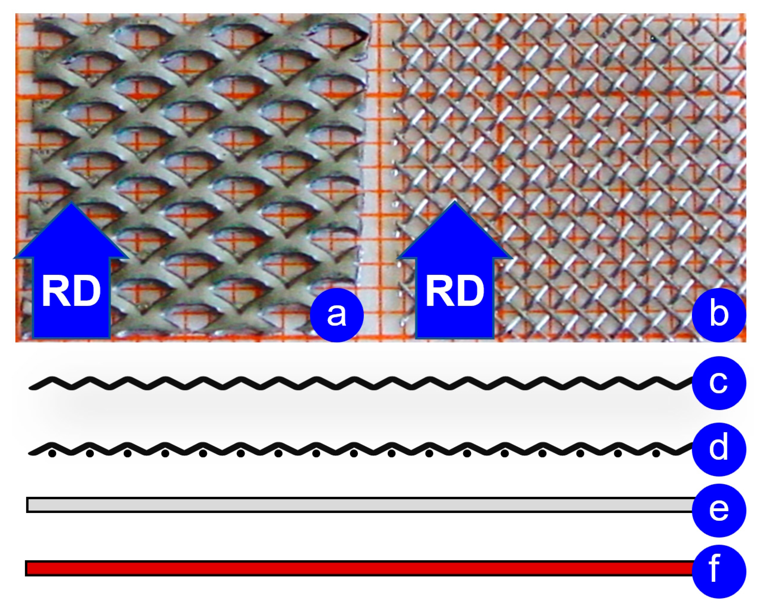
Figure 1. Meshes used to apply the pattern to a matrix surface: (a) expanded mesh; (b) wire mesh; (c) expanded mesh pictogram; (d) wire mesh pictogram; (e) Al-matrix pictogram; (f) Cu-matrix pictogram.
Jmmp 07 00158 g001
Figure 2. Schematic of the roll patterning of the matrix interface with a mesh inlay without creating a lasting bond.
Jmmp 07 00158 g002
Figure 3. The experimental matrix with a pictogram and description for each assembly.
Jmmp 07 00158 g003
Figure 4. Initial angles of the steel-mesh inserts and imprints on the matrices after rolling: (a) initial angle of the expanded mesh; (b) imprints of the expanded mesh on the Al matrix; (c) imprints of the expanded mesh on the Cu matrix; (d) initial angle of the wire mesh; (e) imprints of the wire mesh on the Al matrix; (f) imprints of the wire mesh on the Cu matrix.
Jmmp 07 00158 g004
Figure 5. Visualization of the patterned matrix leaving the deformation zone in the simulation according to the conditions of the experiments: (a) A1, (b) A10, (c) B1 and (d) B10; examples of measured indentation angle (see Figure 4) for numerical experiments (e) A10 and (f) B1; upper roller, upper half of matrix and mesh insert are not visible. RD—rolling direction.
Jmmp 07 00158 g005
Figure 6. Plots of distortion-angle values for experiments and simulations to pattern aluminum matrices with steel netting inlays: (A1) diameter of rolls—65 mm (expanded mesh; ε = 9.2%); (A1S) FE simulation according to A1; (A10) diameter of rolls—65 mm (expanded mesh; ε = 15.2%) (A10S) FE simulation according to A10; (A2) diameter of rolls—65 mm (wire mesh; ε = 11.4%); (A20) diameter of rolls—65 mm (wire mesh; ε = 15.9%); (B1) diameter of rolls—130 mm (expanded mesh; ε = 8.2%); (B1S) FE simulation according to B1; (B10) diameter of rolls—130 mm (expanded mesh; ε = 16.7%); (B10S) FE simulation according to B10; (B2) diameter of rolls—130 mm (wire mesh; ε = 9.4%); (B20) diameter of rolls—130 mm (wire mesh; ε = 16.3%).
Jmmp 07 00158 g006
Figure 7. Values of the experimentally obtained distortion angle to pattern aluminum–copper–aluminum matrices with steel netting inlay: (A3) diameter of rolls—65 mm (expanded mesh; ε = 10%); (A30) diameter of rolls—65 mm (expanded mesh; ε = 29%); (A4) diameter of rolls—65 mm (wire mesh; ε = 11%); (A40) diameter of rolls—65 mm (wire mesh; ε = 21%); (B3) diameter of rolls—130 mm (expanded mesh; ε = 12%); (B30) diameter of rolls—130 mm (expanded mesh; ε = 28%); (B4) diameter of rolls—130 mm (wire mesh; ε = 14%); (B40) diameter of rolls—130 mm (wire mesh; ε = 21.8%); (A30`) diameter of rolls—65 mm (expanded mesh; ε = 14.6%).
Jmmp 07 00158 g007
Figure 8. Visualization of the influence of varying experimental parameters on the distortion of mesh inserts during roll patterning.
Jmmp 07 00158 g008
Figure 9. Patterning of contact surfaces with subsequent roll bonding of three-layer composites in oxygen-free atmosphere: (1) assembly of type   A l 1 + N e x p + C u 1 + N e x p + A l 1 ; (2) roll patterning; (3) removal of the inlay; (4) surface activation and enclosing in a sealer bag in low-oxygen atmosphere or vacuum; (5) roll bonding of assembly of type A l + C u + A l with patterned interfaces inside the PE sealer bag; (6) A l + C u + A l composite with oxide-free inner interfaces.
Jmmp 07 00158 g009
Figure 10. Previously patterned A l + C u + A l composites after rolling in isolating PE sealer bags with an accumulated reduction of 33%: (B300) interface previously patterned with expanded mesh; (B402) interface previously patterned with wire mesh.
Jmmp 07 00158 g010
Figure 11. Specimens after cold roll bonding in isolating PE sealer bags: (a) not patterned   A l + A l composite delaminated after post-rolling operations; (b) previously patterned interface with wire mesh.
Jmmp 07 00158 g011
Table 1. Values of the coefficients in Equations (6) and (7).
Experimental Code k 1 b 1 k 2 b 2
A1–1011 ± 0.18.40.682.25
A2–2011 ± 0.112.40.665.63
B1–106.7 ± 0.158.00.582.78
B2–206.7 ± 0.159.90.584.41
A3–30`9.4 ± 0.21.90.64−2.4
A4–409.4 ± 0.25.00.460.14
B3–306.2 ± 0.16.00.371.6
B4–406.2 ± 0.19.00.333.7
Table 2. Ranking of the experimental parameters relating to values of coefficient from k 2 .
Position Value   of   k 2 Experimental Parameters
AssemblyRoll DiameterExperiment
10.68 A l 1 + N e x p + A l 1 65 mmA1–10
20.66 A l 1 + N w i r e + A l 1 65 mmA2–20
30.64 A l 1 + N e x p + C u 1 + N e x p + A l 1 65 mmA3–30`
40.58 A l 1 + N e x p + A l 1 130 mmB1–10
50.58 A l 1 + N w i r e + A l 1 130 mmB2–20
60.46 A l 1 + N w i r e + C u 1 + N w i r e + A l 1 65 mmA4–40
70.37 A l 1 + N e x p + C u 1 + N e x p + A l 1 130 mmB3–30
80.33 A l 1 + N w i r e + C u 1 + N w i r e + A l 1 130 mmB4–40
Table 3. Ranking of experimental parameters related values of coefficient b 2 .
Position Value   of   b 2 Experimental Parameters
AssemblyRoll
Diameter
Experiment
1−2.4 A l 1 + N e x p + C u 1 + N e x p + A l 1 65 mmA3–30`
20.14 A l 1 + N w i r e + C u 1 + N w i r e + A l 1 65 mmA4–40
31.6 A l 1 + N w i r e + C u 1 + N w i r e + A l 1 130 mmB3–30
42.25 A l 1 + N e x p + A l 1 65 mmA1–10
52.78 A l 1 + N e x p + A l 1 130 mmB1–10
63.7 A l 1 + N w i r e + C u 1 + N w i r e + A l 1 130 mmB4–40
74.41 A l 1 + N w i r e + A l 1 130 mmB2–20
85.63 A l 1 + N w i r e + A l 1 65 mmA2–20
Disclaimer/Publisher’s Note: The statements, opinions and data contained in all publications are solely those of the individual author(s) and contributor(s) and not of MDPI and/or the editor(s). MDPI and/or the editor(s) disclaim responsibility for any injury to people or property resulting from any ideas, methods, instructions or products referred to in the content.