
Process Window and Repeatability of Thermomechanical Tangential Ring Rolling


Abstract
:1. Introduction
2. Materials and Methods
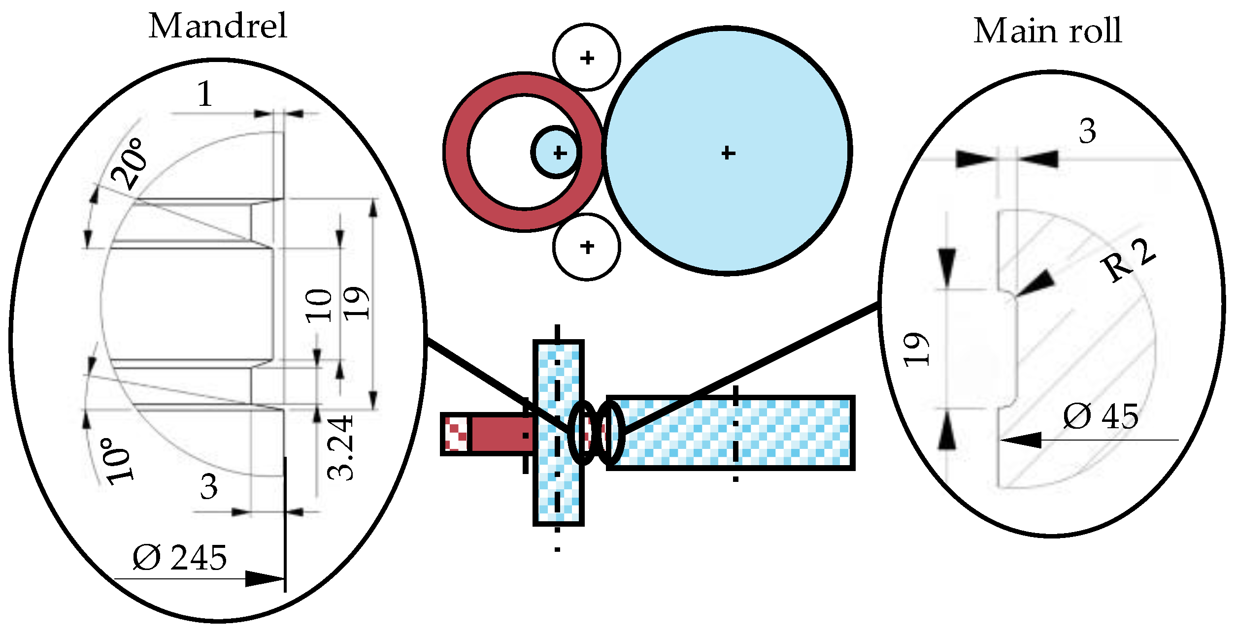
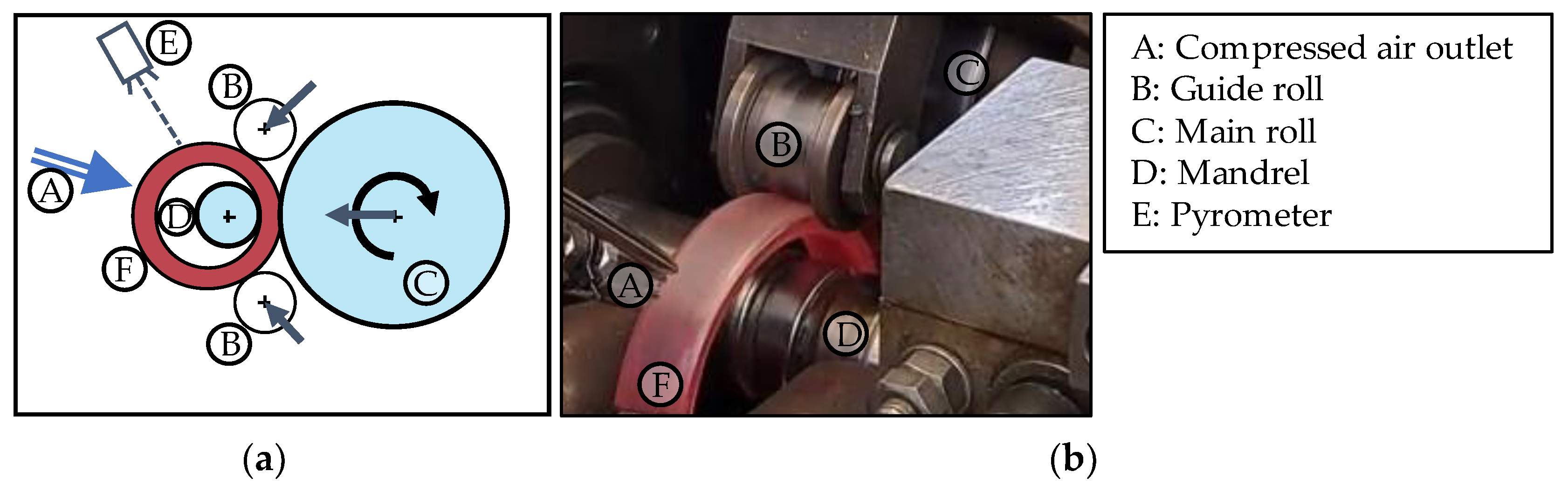
2.1. Experimental Setup
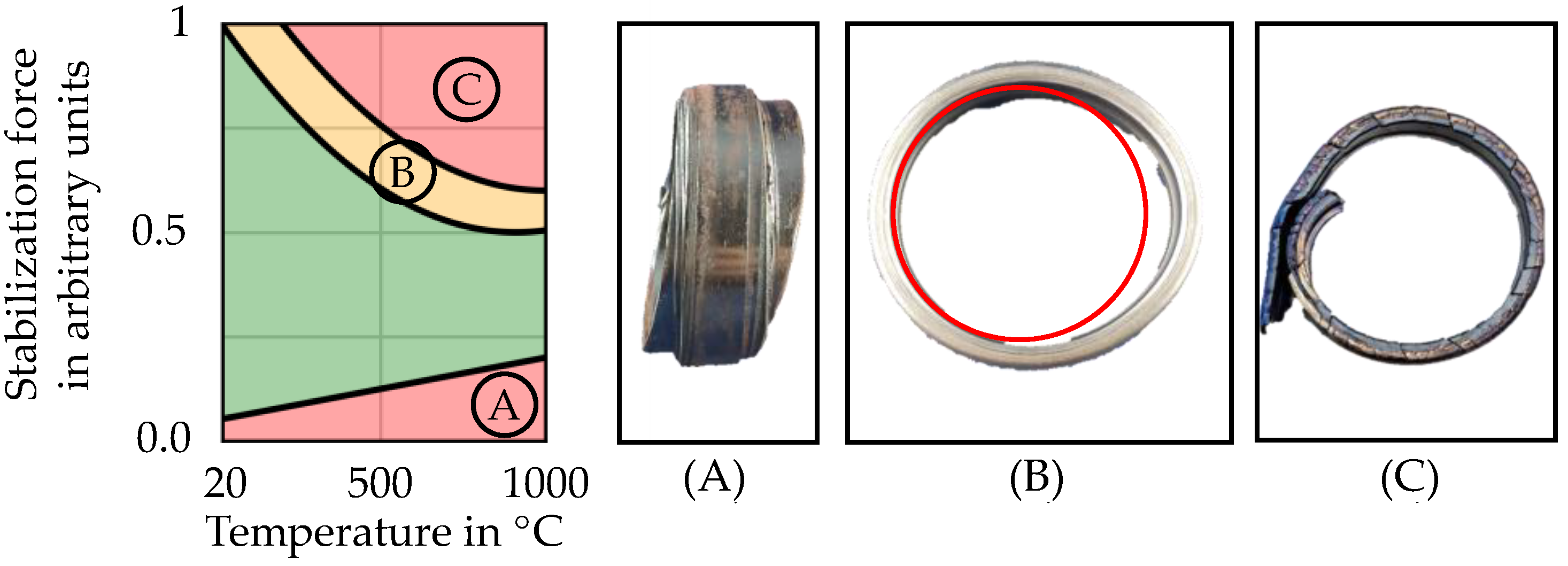
2.2. Process Window of Stability
2.3. Process Parameters and Description
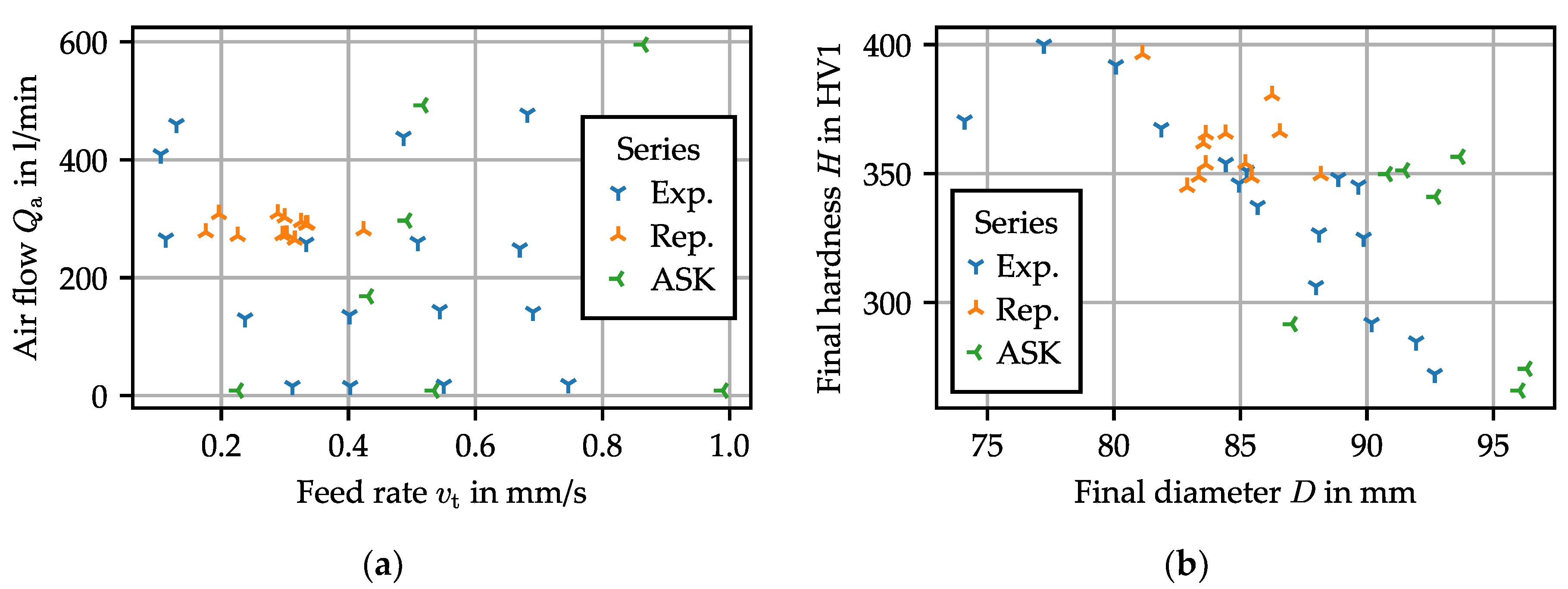
2.4. Design of Experiments
2.5. Hardness Measurement
3. Results
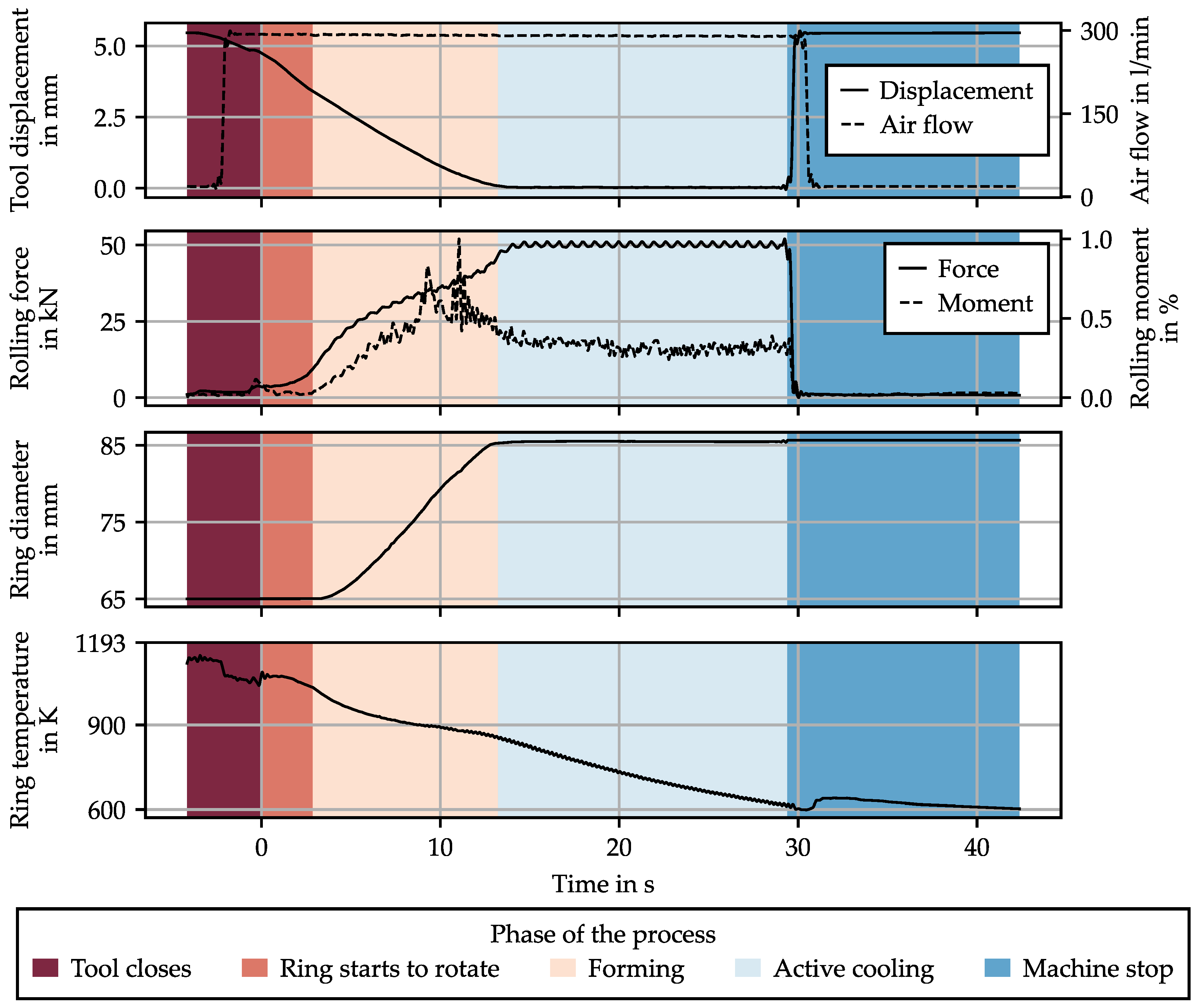
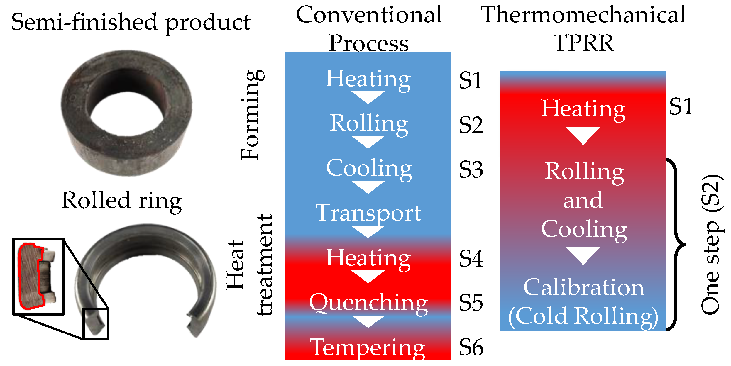
3.1. Process Phases
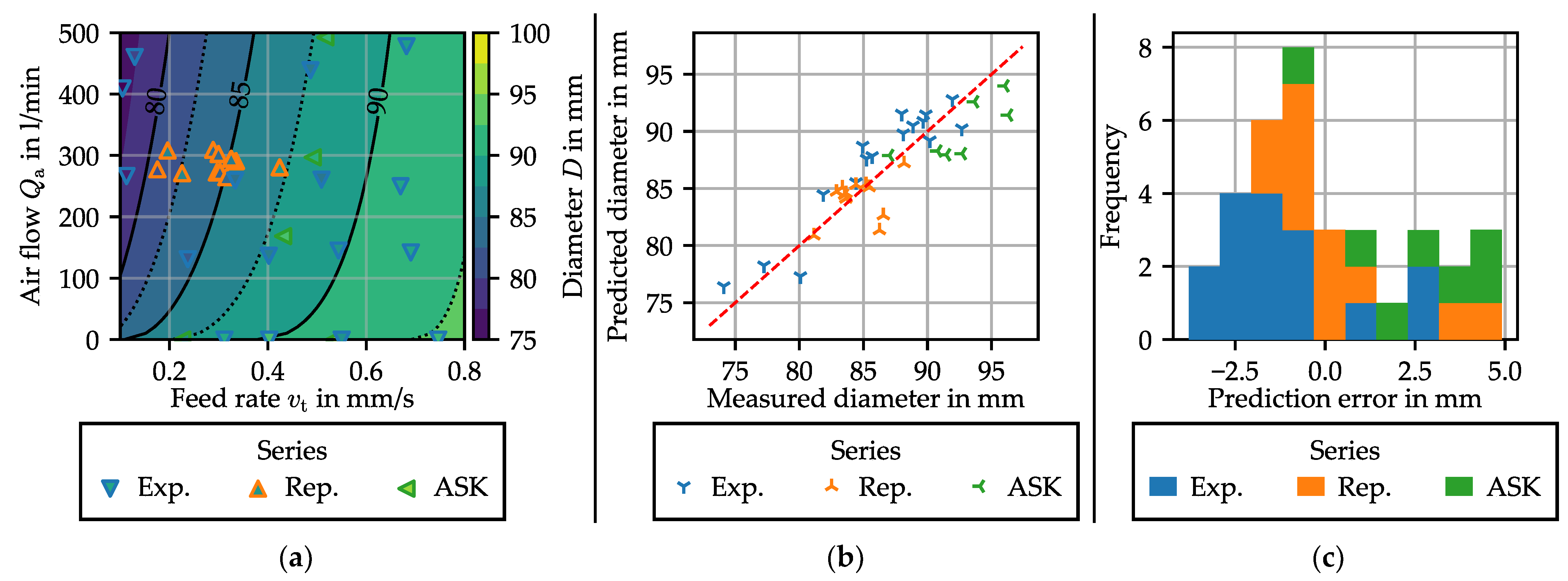
3.2. Process Window Screening
3.2.1. Influence of Process Parameters on the Ring Geometry
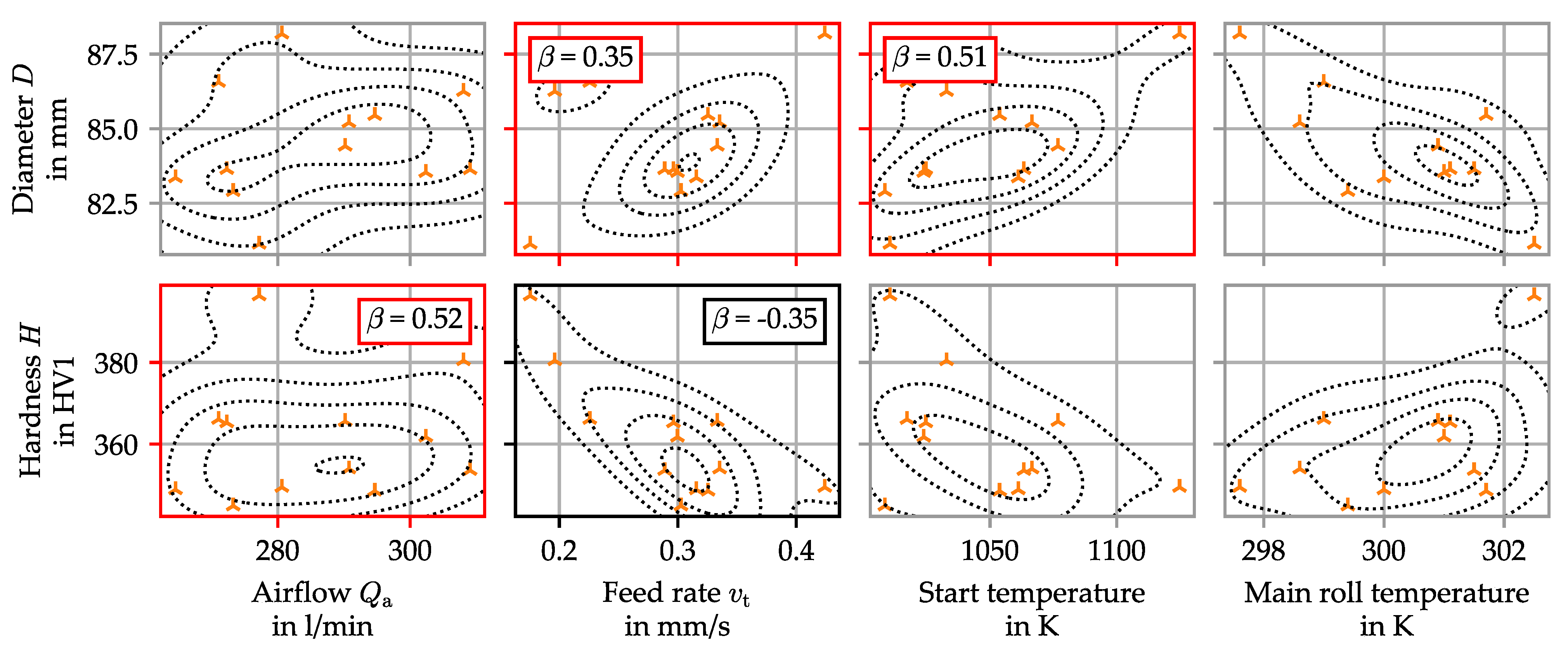
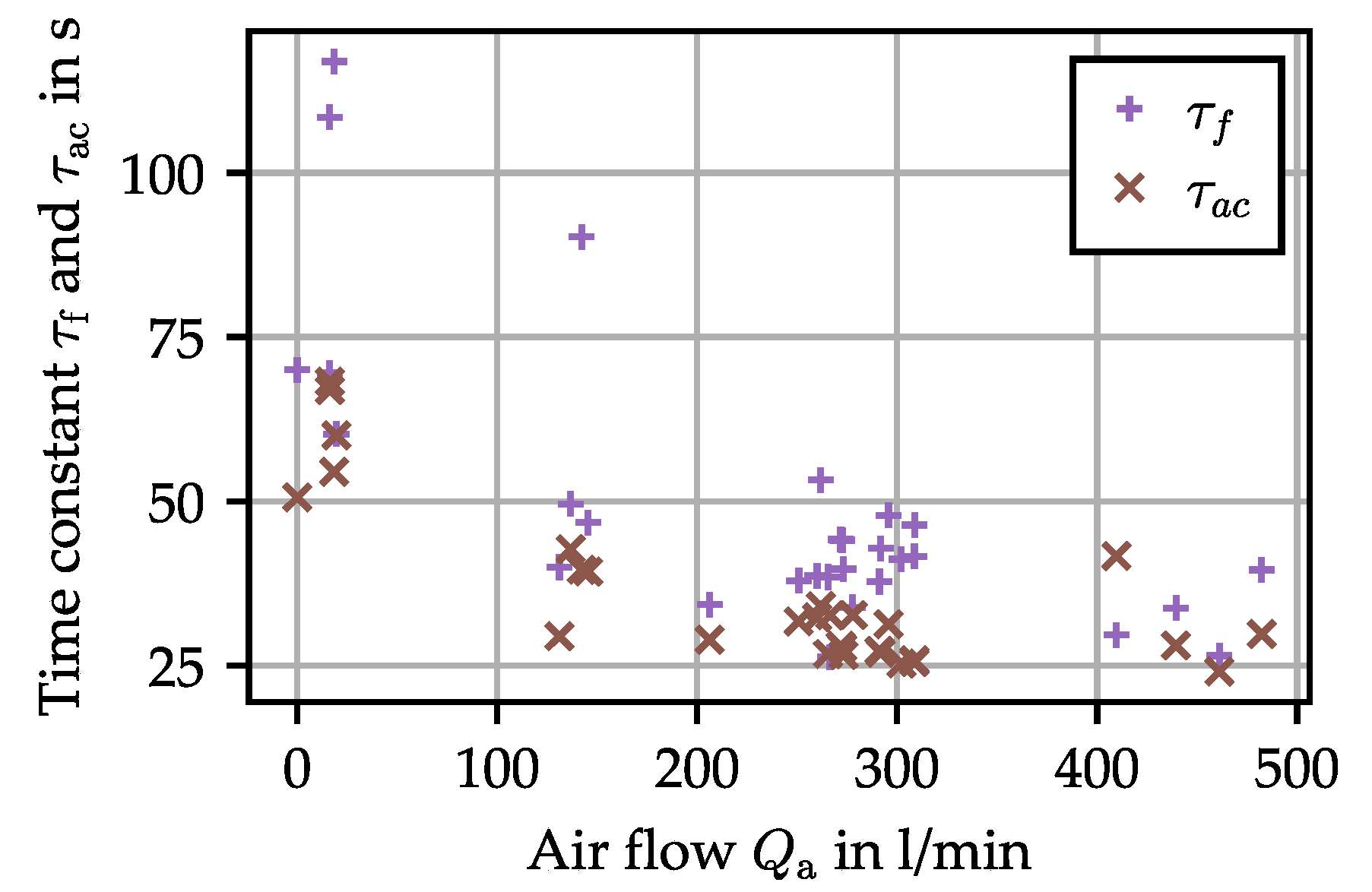
- Friction can be affected by temperature, and in return influence ring growth. The tangential friction stress is limited to the yield shear stress of the material. This value is often attained in hot and semi-hot forming [12]. The yield stress being strongly dependent on temperature, this could change the flow of the metal in the forming zone, resulting in a change of diameter.
- For the ring radius to grow, the ring curvature at each point must change: as the ring elongates in the deformation zone, the rest of the ring must bend. This effect has been modeled as an elastic bending of the ring in semi-analytical models [13], implying that the reaction force to curvature change is directly proportional to the elastic modulus. As the ring cools down, the Young’s modulus of the material increases, and so does the tangential stiffness. The higher stiffness limits the ability of the material to flow in the tangential direction within the forming zone.
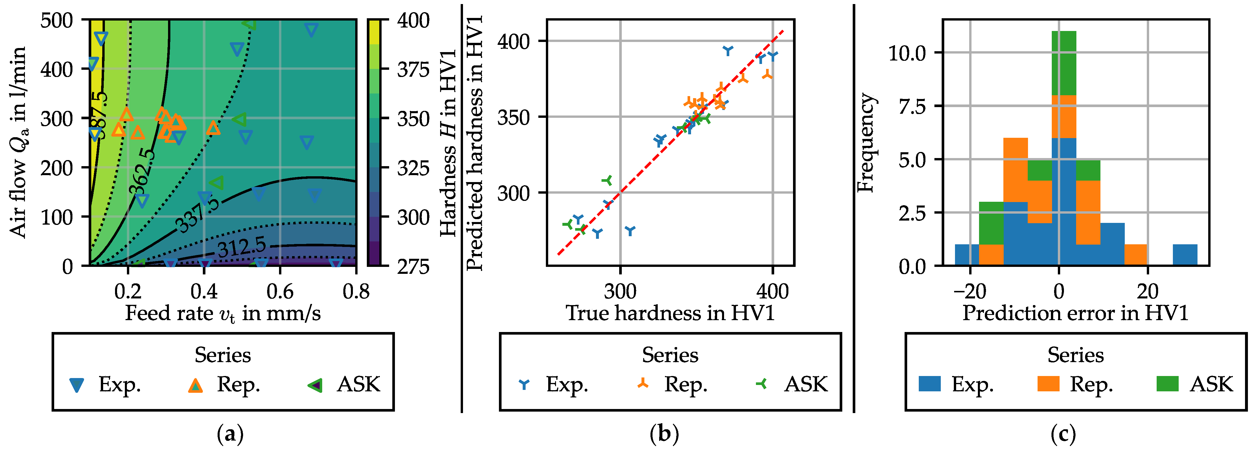
3.2.2. Influence of the Process Parameters on the Ring Hardness
- A slower feed rate means that the forming phase is longer. As the cooling rate is lower during this phase, this reduces the quantity of hard phase being formed during the process.
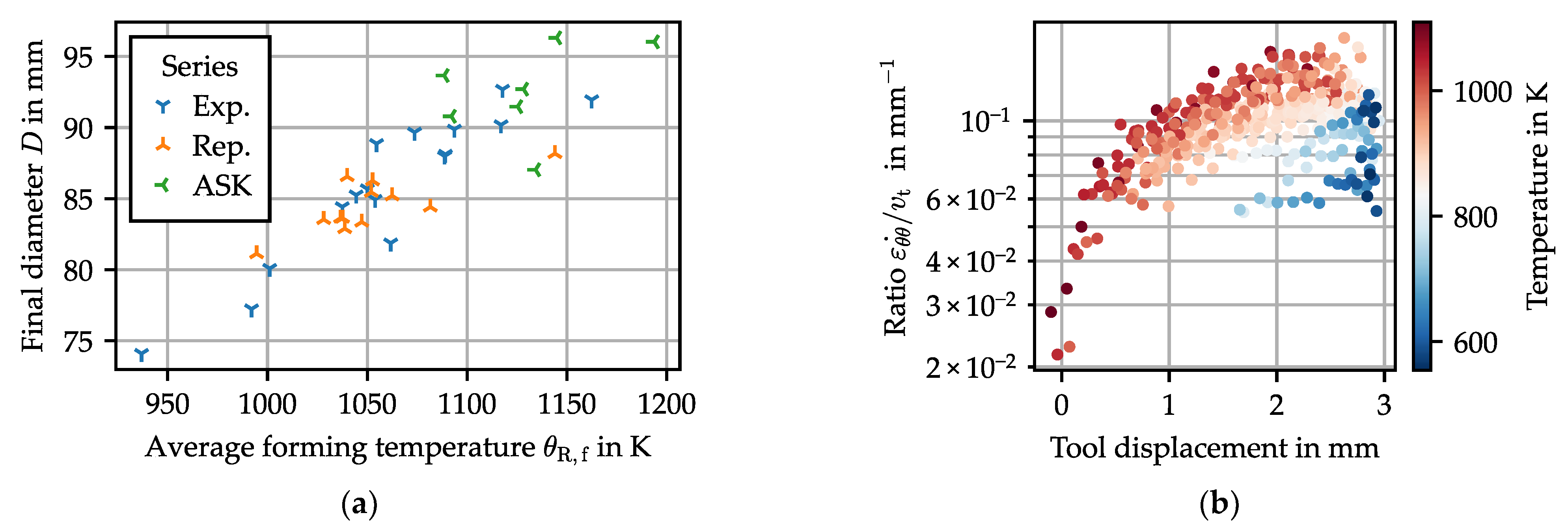
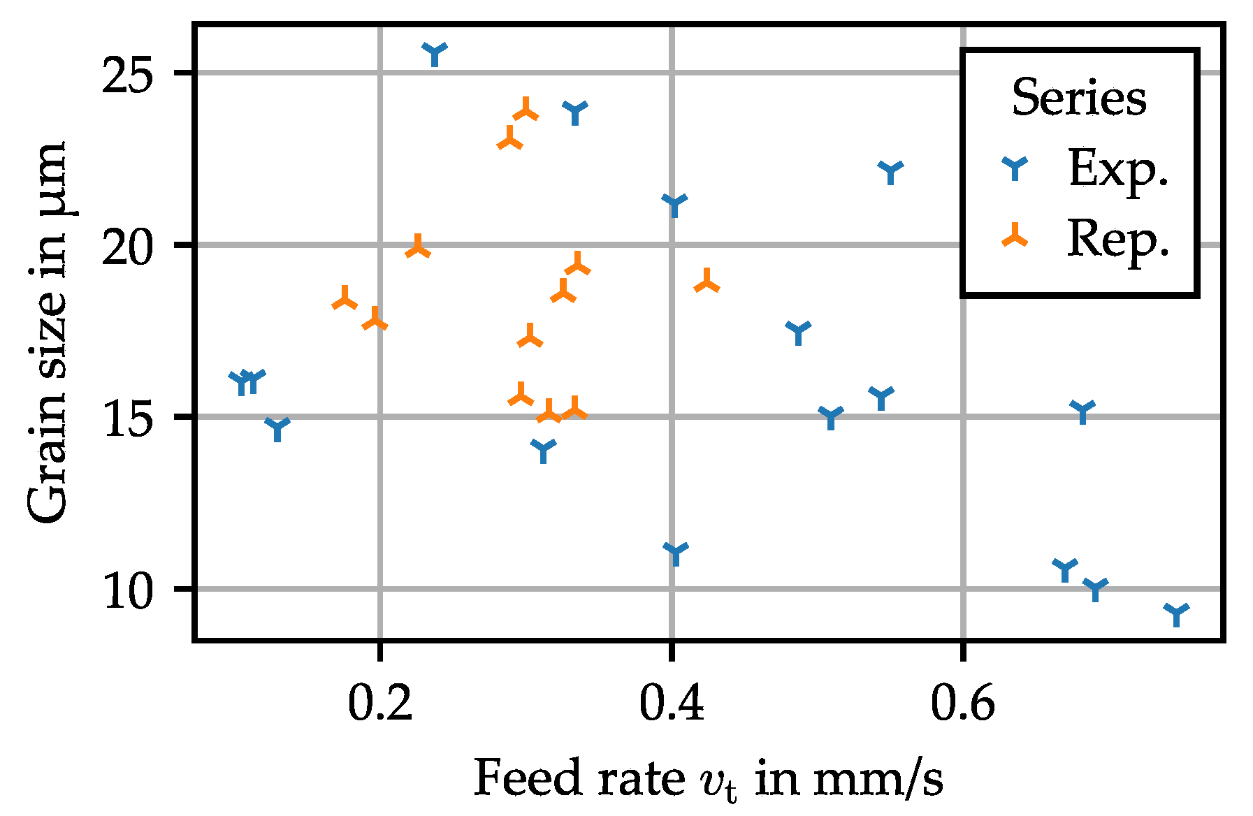
- A higher feed rate means a higher strain rate. Since forming begins at high temperature, this will affect the amount of recrystallization occurring during the early stages of forming. In this case, this will be mostly dynamic recrystallization triggered by the continuous production of dislocations during the forming process. This hypothesis is supported by a decrease of grain size with feed rate, as shown in Figure 13 (, ). Following the Hall–Petch relation, this increases the measured hardness [14].
3.3. Process Repeatability
- Tool surface temperature: During the process, both tools are heated through contact with the hot work piece. They cool down between the experiments. After a few experiments, an equilibrium is reached, which is dependent on the downtime between two experiments. Even after a few “warm-up” rings, there is always a variation of the tool temperature, albeit of lower magnitude. Because the thermal conduction between the tool and the ring is proportional to their temperature difference, this can influence the cooling rate of the ring and could therefore impact both the diameter and the hardness.
- Start temperature: Even assuming that the temperature in the furnace is homogeneous and constant, there is still a possibility of having a significant variation of the start temperature. Indeed, the transfer of the part, the closure of the mandrel, and the machine startup is realized manually. During this time, the part is cooling down at around 5 K/s.
4. Conclusions and Perspectives
- Obtaining a sufficient process capability will require advanced control systems, for each machine actuator but also for the process itself, using model process control techniques.
- As in every hot or semi-hot forming operation, tool wear might become a challenge, especially when harder material is used.
- The results presented in this paper need to be confirmed using material with a better hardenability, such as 100Cr6 steels. The suitability of the process for harder steel must be validated, especially when some forming occurs at lower temperature.
Author Contributions
Funding
Data Availability Statement
Conflicts of Interest
References
- Allwood, J.M.; Tekkaya, A.E.; Stanistreet, T.F. The Development of Ring Rolling Technology. Steel Res. Int. 2005, 76, 111–120. [Google Scholar] [CrossRef]
- Groche, P.; Fritsche, D.; Tekkaya, E.A.; Allwood, J.M.; Hirt, G.; Neugebauer, R. Incremental Bulk Metal Forming. CIRP Ann. 2007, 56, 635–656. [Google Scholar] [CrossRef]
- Allwood, J.M. A Structured Search for Novel Manufacturing Processes Leading to a Periodic Table of Ring Rolling Machines. J. Mech. Des. 2007, 129, 502–511. [Google Scholar] [CrossRef]
- Ficker, T.; Hardtmann, A.; Houska, M. Ring Rolling Research at the Dresden University of Technology—Its History from the Beginning in the 70s to the Present. Steel Res. Int. 2005, 76, 121–124. [Google Scholar] [CrossRef]
- Berthold, R.; Heinrich, P. Walzkorper und Innenringe automatisiert herstellen auf Profil-Kaltwalzmaschinen. Maschinenmarkt 1984, 90, 720–723. [Google Scholar]
- Profiroll-Prozesskettenalternative. Available online: https://www.profiroll.de/fileadmin/user_upload/4_verfahren/3_ringwalzen/Profiroll-Prozesskettenalternative.pdf (accessed on 23 February 2023).
- Erberlein, L. Lange Lebensdauer: Kaltwalzen von Kugellagerringen ist wirtschaftlische Alternative zum Spanen. Maschinenmarkt 1994, 100, 28–34. [Google Scholar]
- Brosius, A.; Tulke, M.; Guilleaume, C. Non-linear model-predictive-control for thermomechanical ring rolling. In Proceedings of the XIV International Conference on Computational Plasticity: Fundamentals and Applications COMPLAS 2019, Barcelona, Spain, 3–5 September 2019; pp. 499–509. [Google Scholar]
- Lafarge, R.; Hütter, S.; Michael, O.; Halle, T.; Brosius, A. Property Controlled Ring Rolling: Process Implementation and Window. In Ideen Form Geben, 36. ASK Umformtechnik: 26–27 Oktober 2022, Eurogress Aachen: Tagungsband; Verlagshaus Mainz GmbH: Aachen, Germany, 2022; pp. 225–234. ISBN 9783958864603. [Google Scholar]
- Ghattamaneni, M.C.; Wernicke, S.; Hainmann, T.S.; Sulaiman, H.; Tekkaya, A.E. Analysis, Prediction and Reduction of Emissions in an Industrial Hot Forming Process Chain for the Manufacture of Sheet Metal Components. KEM 2022, 926, 2342–2354. [Google Scholar] [CrossRef]
- Zayadi, H.; Parvizi, A.; Farahmand, H.R.; Rahmatabadi, D. Investigation of Ring Rolling Key Parameters for Decreasing Geometrical Ring Defects by 3D Finite Element and Experiments. Arab. J. Sci. Eng. 2021, 46, 12105–12115. [Google Scholar] [CrossRef]
- Petty, D.M. Friction models for finite element modelling. J. Mater. Process. Technol. 1994, 45, 7–12. [Google Scholar] [CrossRef]
- Tszeng, T.C.; Altan, T. Investigation of ring rolling by pseudo plane-strain FEM analysis. J. Mater. Process. Technol. 1991, 27, 151–161. [Google Scholar] [CrossRef]
- Hansen, N. Hall-Petch relation and boundary strengthening. Scr. Mater. 2004, 51, 801–806. [Google Scholar] [CrossRef]
- Lafarge, R.; Hütter, S.; Tulke, M.; Halle, T.; Brosius, A. Data based model predictive control for ring rolling. Prod. Eng. Res. Dev. 2021, 15, 821–831. [Google Scholar] [CrossRef]


| Series Name | Experiments IDs | Airflow Value in L/min | Mandrel Feed Control Value | Corresponding Theoretical Feed |
|---|---|---|---|---|
| Preliminary work (ASK) [9] | ASK_A–ASK_G | 0 up to 600 | 4.5 up to 8.5 | 0.15 up to 1.0 |
| Repeatability (Rep.) | A1–A12 | 300 | 6 | 0.3 |
| Exploration (Exp.) | B–R | 0 up to 500 | 5.5 up to 8 | 0.25 up to 0.75 |
Disclaimer/Publisher’s Note: The statements, opinions and data contained in all publications are solely those of the individual author(s) and contributor(s) and not of MDPI and/or the editor(s). MDPI and/or the editor(s) disclaim responsibility for any injury to people or property resulting from any ideas, methods, instructions or products referred to in the content. |
© 2023 by the authors. Licensee MDPI, Basel, Switzerland. This article is an open access article distributed under the terms and conditions of the Creative Commons Attribution (CC BY) license (https://creativecommons.org/licenses/by/4.0/).
Share and Cite
Lafarge, R.; Hütter, S.; Halle, T.; Brosius, A. Process Window and Repeatability of Thermomechanical Tangential Ring Rolling. J. Manuf. Mater. Process. 2023, 7, 98. https://doi.org/10.3390/jmmp7030098
Lafarge R, Hütter S, Halle T, Brosius A. Process Window and Repeatability of Thermomechanical Tangential Ring Rolling. Journal of Manufacturing and Materials Processing. 2023; 7(3):98. https://doi.org/10.3390/jmmp7030098
Chicago/Turabian StyleLafarge, Rémi, Sebastian Hütter, Thorsten Halle, and Alexander Brosius. 2023. "Process Window and Repeatability of Thermomechanical Tangential Ring Rolling" Journal of Manufacturing and Materials Processing 7, no. 3: 98. https://doi.org/10.3390/jmmp7030098
APA StyleLafarge, R., Hütter, S., Halle, T., & Brosius, A. (2023). Process Window and Repeatability of Thermomechanical Tangential Ring Rolling. Journal of Manufacturing and Materials Processing, 7(3), 98. https://doi.org/10.3390/jmmp7030098