A Review of the Recent Developments and Challenges in Wire Arc Additive Manufacturing (WAAM) Process
Abstract
1. Introduction
2. WAAM Process
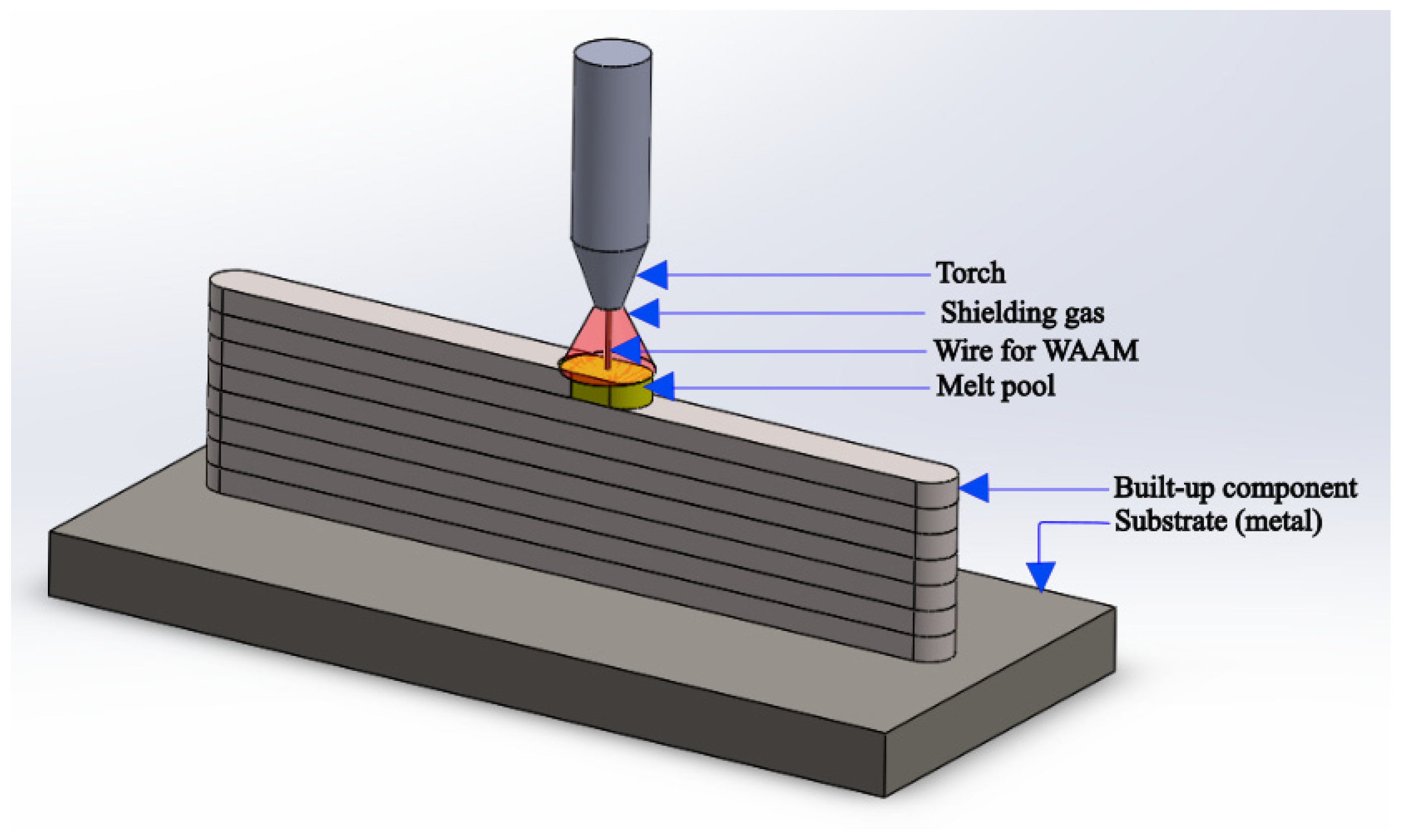
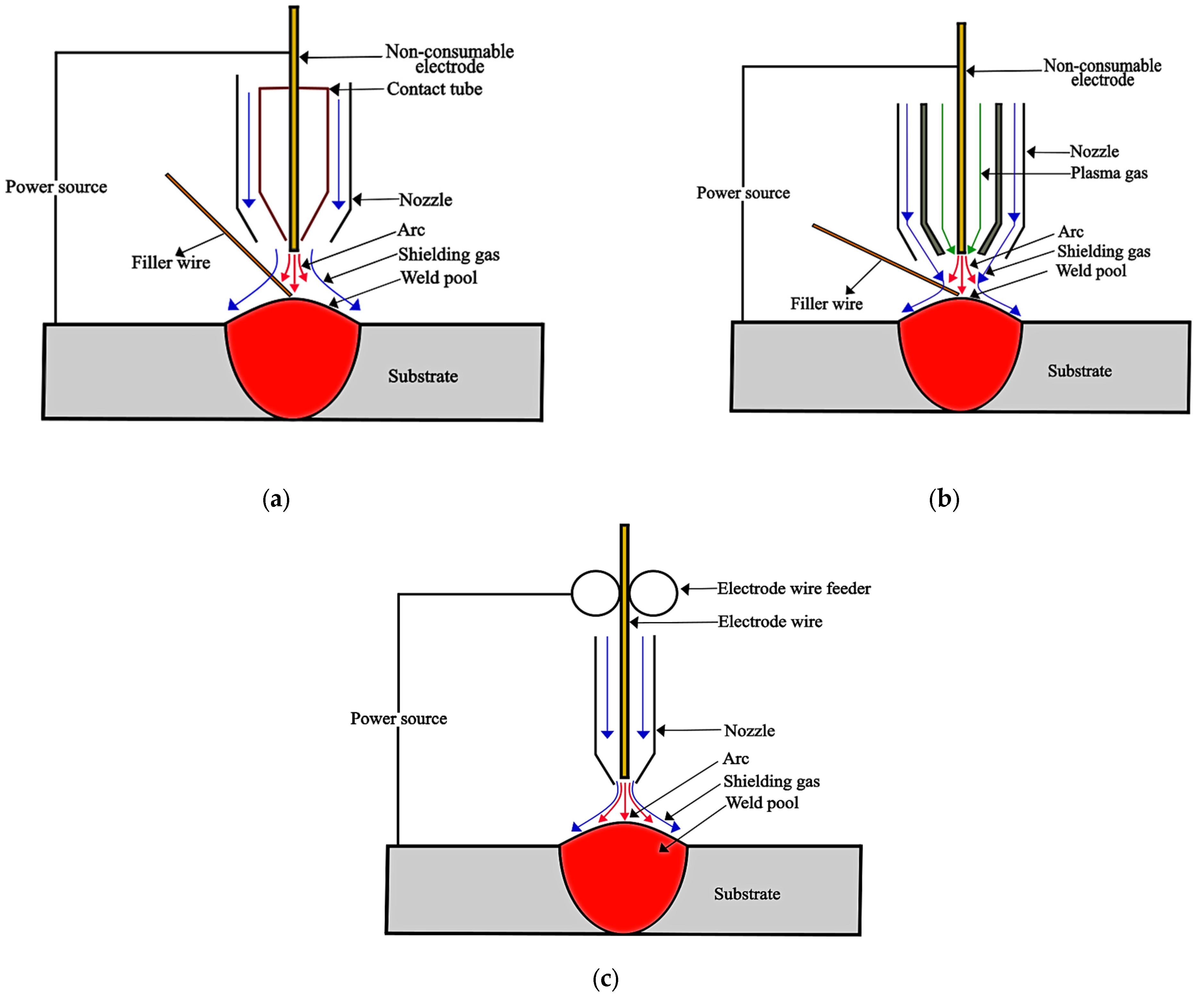
2.1. Introduction to WAAM
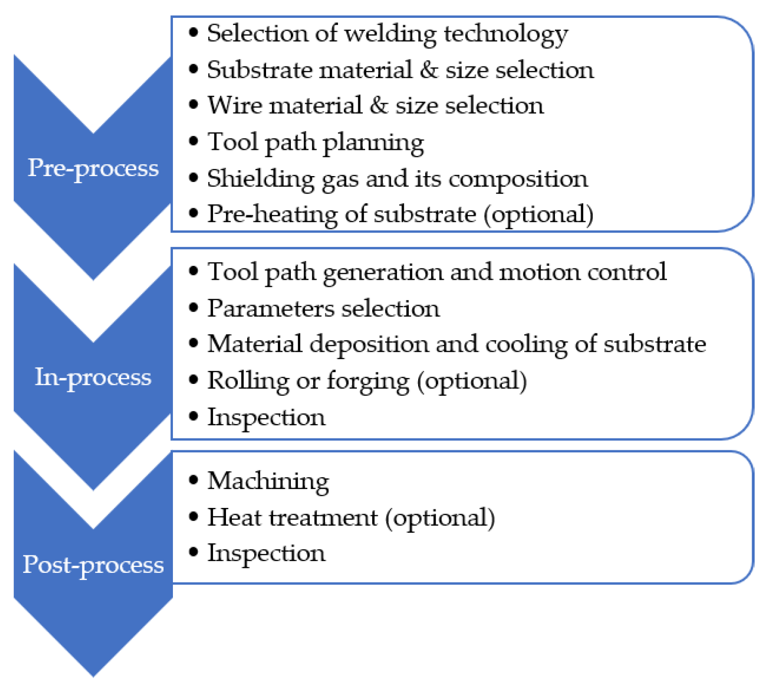
2.2. General Steps Involved in WAAM Process
2.3. Process Parameters Used in WAAM Process
2.3.1. Introduction to Different WAAM Process Parameters
Wire Feed Speed
Torch Travel Speed
Heat Input
| = Heat input per unit length | = Efficiency | = Voltage |
| = Travel speed | = Current |
Substrate Temperature
Interlayer Temperature
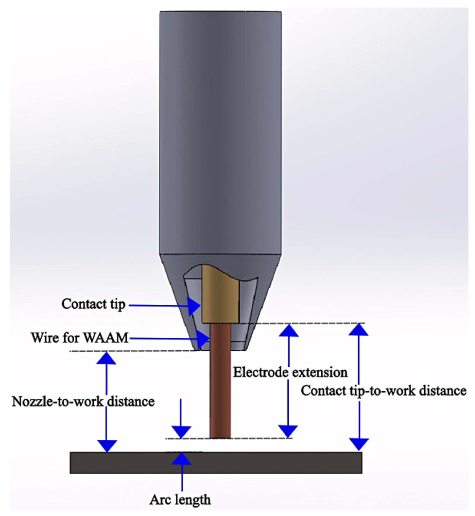
Electrode Extension or Electrode Stick-Out
Arc Length
2.4. Challenges in WAAM Process and Parameters Affecting the Product Quality
2.4.1. Defects in WAAM Process
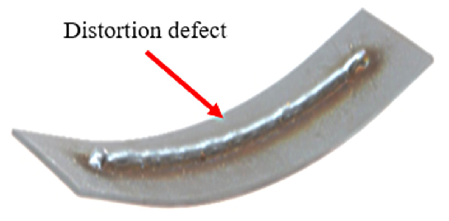
Distortion and Residual Stresses
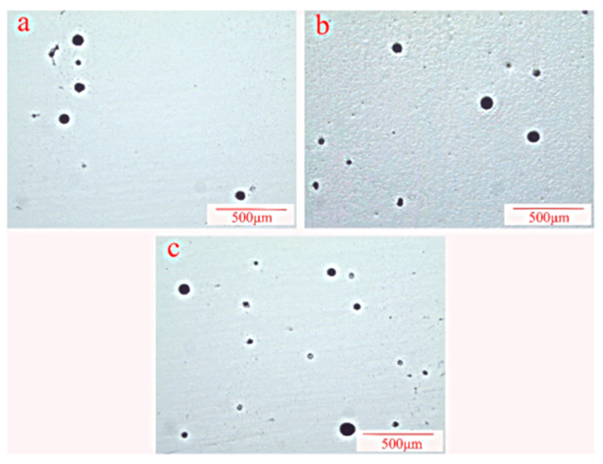
Porosity
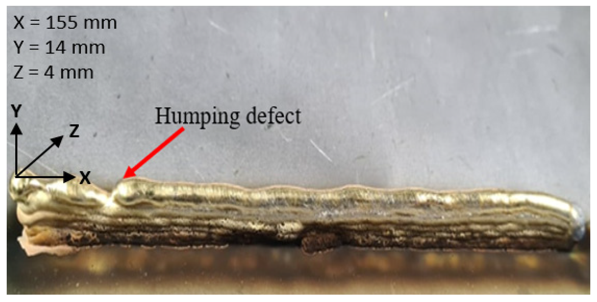
Humping Defect
Material Overflow
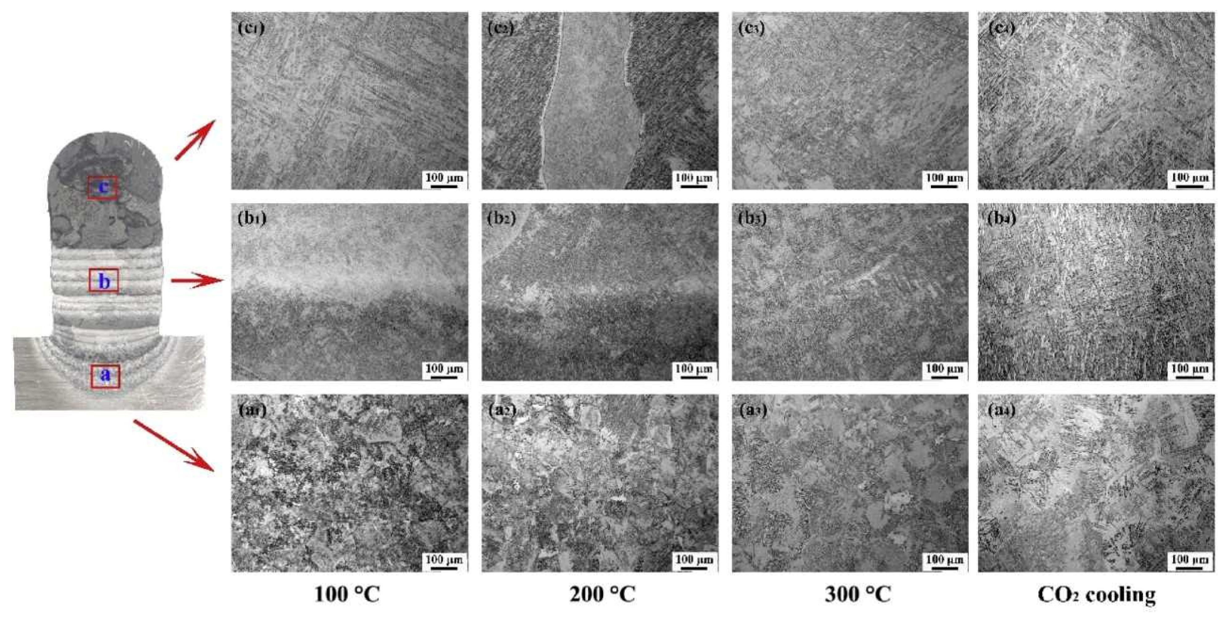
2.4.2. Inhomogeneous Microstructure
2.4.3. Controlling Mechanical Properties of WAAM Products
2.5. Methodologies to Enhance the Quality of WAAM Products
2.5.1. Optimal Process Parameters
2.5.2. Path Strategy
Single Bead Multiple Passes
Multiple Beads, Multiple Passes
2.5.3. Appropriate Shielding Gas
2.5.4. In-Process Operations in WAAM Process for Quality Improvement
Hybrid WAAM Process
Additional Steps for Improving Material Properties
2.5.5. Post-Process Operations
Milling (Mandatory)
Other Non-Mandatory Post-Process Operations (Optional)
2.5.6. Process Monitoring
3. A Brief Overview of Different Wire Materials Used in WAAM Process
3.1. Single-Wire WAAM Process
3.2. Multi-Wires WAAM Process
3.3. WAAM of Copper-Based Materials
4. Conclusions and Future Research Directions
- WAAM is a promising technology for fabricating parts/components with complex geometries. It has been explored for metal alloys such as steel, aluminium, etc. However, it should be explored further for new advanced materials such as functionally graded materials;
- Material deposition in WAAM process is generally accompanied by different types of defects and challenges, i.e., material overflow, poor weld bead quality, humping defects, etc. These problems can be addressed via suitable parameter selection and an optimal material deposition strategy;
- In-process operations, i.e., rolling, forging, etc., can enhance the microstructure and mechanical properties of simple WAAM products. However, for complex geometries, suitable in-process operations need to be developed. Furthermore, post-process operations are also crucial for enhancing microstructure and mechanical properties;
- Defect generation is associated with different signals, i.e., optical, thermal, etc. These signals can be sensed accurately by employing an advanced signal detection system to ensure and improve the quality of WAAM products. Furthermore, non-destructive testing techniques should be utilized to assess the in-service performance and life of WAAM products;
- It was found that the correlation between process parameters and part quality has not yet been sufficiently explored. It should be further investigated using the specific test methodology, and the relationship should be described as a model. Hence, a WAAM process that meets quality requirements can be developed in the planning phase.
Author Contributions
Funding
Data Availability Statement
Conflicts of Interest
Correction Statement
References
- Karakurt, I.; Lin, L. 3D Printing Technologies: Techniques, Materials, and Post-Processing. Curr. Opin. Chem. Eng. 2020, 28, 134–143. [Google Scholar] [CrossRef]
- Raut, L.P.; Taiwade, R.V. Wire Arc Additive Manufacturing: A Comprehensive Review and Research Directions. J. Mater. Eng. Perform. 2021, 30, 4768–4791. [Google Scholar] [CrossRef]
- Li, Y.; Su, C.; Zhu, J. Comprehensive Review of Wire Arc Additive Manufacturing: Hardware System, Physical Process, Monitoring, Property Characterization, Application and Future Prospects. Results Eng. 2021, 13, 100330. [Google Scholar] [CrossRef]
- Pagac, M.; Hajnys, J.; Ma, Q.-P.; Jancar, L.; Jansa, J.; Stefek, P.; Mesicek, J. A Review of Vat Photopolymerization Technology: Materials, Applications, Challenges, and Future Trends of 3D Printing. Polymers 2021, 13, 598. [Google Scholar] [CrossRef] [PubMed]
- Alfattni, R. Comprehensive Study on Materials Used in Different Types of Additive Manufacturing and Their Applications. Int. J. Math. Eng. Manag. Sci. 2022, 7, 92. [Google Scholar] [CrossRef]
- Lv, X.; Ye, F.; Cheng, L.; Fan, S.; Liu, Y. Binder Jetting of Ceramics: Powders, Binders, Printing Parameters, Equipment, and Post-Treatment. Ceram. Int. 2019, 45, 12609–12624. [Google Scholar] [CrossRef]
- Gülcan, O.; Günaydın, K.; Tamer, A. The State of the Art of Material Jetting—A Critical Review. Polymers 2021, 13, 2829. [Google Scholar] [CrossRef]
- Gibson, I.; Rosen, D.W.; Stucker, B.; Khorasani, M.; Rosen, D.; Stucker, B.; Khorasani, M. Additive Manufacturing Technologies; Springer: Berlin/Heidelberg, Germany, 2021; Volume 17. [Google Scholar]
- Thapliyal, S. Challenges Associated with the Wire Arc Additive Manufacturing (WAAM) of Aluminum Alloys. Mater. Res. Express 2019, 6, 112006. [Google Scholar] [CrossRef]
- Lehmann, T.; Rose, D.; Ranjbar, E.; Ghasri-Khouzani, M.; Tavakoli, M.; Henein, H.; Wolfe, T.; Jawad Qureshi, A. Large-Scale Metal Additive Manufacturing: A Holistic Review of the State of the Art and Challenges. Int. Mater. Rev. 2022, 67, 410–459. [Google Scholar] [CrossRef]
- Svetlizky, D.; Das, M.; Zheng, B.; Vyatskikh, A.L.; Bose, S.; Bandyopadhyay, A.; Schoenung, J.M.; Lavernia, E.J.; Eliaz, N. Directed Energy Deposition (DED) Additive Manufacturing: Physical Characteristics, Defects, Challenges and Applications. Mater. Today 2021, 49, 271–295. [Google Scholar] [CrossRef]
- Frazier, W.E. Metal Additive Manufacturing: A Review. J. Mater. Eng. Perform. 2014, 23, 1917–1928. [Google Scholar] [CrossRef]
- Zhai, W.; Wu, N.; Zhou, W. Effect of Interpass Temperature on Wire Arc Additive Manufacturing Using High-Strength Metal-Cored Wire. Metals 2022, 12, 212. [Google Scholar] [CrossRef]
- Rodrigues, T.A.; Duarte, V.; Miranda, R.M.; Santos, T.G.; Oliveira, J.P. Current Status and Perspectives on Wire and Arc Additive Manufacturing (WAAM). Materials 2019, 12, 1121. [Google Scholar] [CrossRef] [PubMed]
- Zhang, Y.M.; Li, P.; Chen, Y.; Male, A.T. Automated System for Welding-Based Rapid Prototyping. Mechatronics 2002, 12, 37–53. [Google Scholar] [CrossRef]
- Zhang, Y.; Chen, Y.; Li, P.; Male, A.T. Weld Deposition-Based Rapid Prototyping: A Preliminary Study. J. Mater. Process. Technol. 2003, 135, 347–357. [Google Scholar] [CrossRef]
- Xiong, J.; Zhang, G. Adaptive Control of Deposited Height in GMAW-Based Layer Additive Manufacturing. J. Mater. Process. Technol. 2014, 214, 962–968. [Google Scholar] [CrossRef]
- Ahn, D.-G. Direct Metal Additive Manufacturing Processes and Their Sustainable Applications for Green Technology: A Review. Int. J. Precis. Eng. Manuf.-Green Technol. 2016, 3, 381–395. [Google Scholar] [CrossRef]
- Suryakumar, S.; Karunakaran, K.P.; Bernard, A.; Chandrasekhar, U.; Raghavender, N.; Sharma, D. Weld Bead Modeling and Process Optimization in Hybrid Layered Manufacturing. Comput.-Aided Des. 2011, 43, 331–344. [Google Scholar] [CrossRef]
- Liu, J.; Xu, Y.; Ge, Y.; Hou, Z.; Chen, S. Wire and Arc Additive Manufacturing of Metal Components: A Review of Recent Research Developments. Int. J. Adv. Manuf. Technol. 2020, 111, 149–198. [Google Scholar] [CrossRef]
- Tawfik, M.M.; Nemat-Alla, M.M.; Dewidar, M.M. Enhancing the Properties of Aluminum Alloys Fabricated Using Wire+ Arc Additive Manufacturing Technique—A Review. J. Mater. Res. Technol. 2021, 13, 754–768. [Google Scholar] [CrossRef]
- Tian, C.L.; Chen, J.L.; Dong, P.; He, J.W.; Wang, Y.J. Current State and Future Development of the Wire Arc Additive Manufacture Technology Abroad. Aerosp. Manuf. Technol. 2015, 2, 57–60. [Google Scholar]
- Furukawa, K. New CMT Arc Welding Process–Welding of Steel to Aluminium Dissimilar Metals and Welding of Super-Thin Aluminium Sheets. Weld. Int. 2006, 20, 440–445. [Google Scholar] [CrossRef]
- Taşdemir, A.; Nohut, S. An Overview of Wire Arc Additive Manufacturing (WAAM) in Shipbuilding Industry. Ships Offshore Struct. 2021, 16, 797–814. [Google Scholar] [CrossRef]
- Yildiz, A.S.; Davut, K.; Koc, B.; Yilmaz, O. Wire Arc Additive Manufacturing of High-Strength Low Alloy Steels: Study of Process Parameters and Their Influence on the Bead Geometry and Mechanical Characteristics. Int. J. Adv. Manuf. Technol. 2020, 108, 3391–3404. [Google Scholar] [CrossRef]
- Wang, H.; Jiang, W.; Ouyang, J.; Kovacevic, R. Rapid Prototyping of 4043 Al-Alloy Parts by VP-GTAW. J. Mater. Process. Technol. 2004, 148, 93–102. [Google Scholar] [CrossRef]
- Dinovitzer, M.; Chen, X.; Laliberte, J.; Huang, X.; Frei, H. Effect of Wire and Arc Additive Manufacturing (WAAM) Process Parameters on Bead Geometry and Microstructure. Addit. Manuf. 2019, 26, 138–146. [Google Scholar] [CrossRef]
- Wu, B.; Pan, Z.; Ding, D.; Cuiuri, D.; Li, H. Effects of Heat Accumulation on Microstructure and Mechanical Properties of Ti6Al4V Alloy Deposited by Wire Arc Additive Manufacturing. Addit. Manuf. 2018, 23, 151–160. [Google Scholar] [CrossRef]
- Suryakumar, S.; Karunakaran, K.P.; Chandrasekhar, U.; Somashekara, M.A. A Study of the Mechanical Properties of Objects Built through Weld-Deposition. Proc. Inst. Mech. Eng. Part B J. Eng. Manuf. 2013, 227, 1138–1147. [Google Scholar] [CrossRef]
- Oliveira, J.P.; Santos, T.G.; Miranda, R.M. Revisiting Fundamental Welding Concepts to Improve Additive Manufacturing: From Theory to Practice. Prog. Mater. Sci. 2020, 107, 100590. [Google Scholar] [CrossRef]
- Pattanayak, S.; Sahoo, S.K. Gas Metal Arc Welding Based Additive Manufacturing—A Review. CIRP J. Manuf. Sci. Technol. 2021, 33, 398–442. [Google Scholar] [CrossRef]
- Abe, T.; Kaneko, J.; Sasahara, H. Thermal Sensing and Heat Input Control for Thin-Walled Structure Building Based on Numerical Simulation for Wire and Arc Additive Manufacturing. Addit. Manuf. 2020, 35, 101357. [Google Scholar] [CrossRef]
- Ouyang, J.H.; Wang, H.; Kovacevic, R. Rapid Prototyping of 5356-Aluminum Alloy Based on Variable Polarity Gas Tungsten Arc Welding: Process Control and Microstructure. Mater. Manuf. Process. 2002, 17, 103–124. [Google Scholar] [CrossRef]
- Qi, K.; Li, R.; Hu, Z.; Bi, X.; Li, T.; Yue, H.; Zhang, B. Forming Appearance Analysis of 2205 Duplex Stainless Steel Fabricated by Cold Metal Transfer (CMT) Based Wire and Arc Additive Manufacture (WAAM) Process. J. Mater. Eng. Perform. 2022, 31, 4631–4641. [Google Scholar] [CrossRef]
- Spencer, J.D.; Dickens, P.M.; Wykes, C.M. Rapid Prototyping of Metal Parts by Three-Dimensional Welding. Proc. Inst. Mech. Eng. Part B J. Eng. Manuf. 1998, 212, 175–182. [Google Scholar] [CrossRef]
- da Silva, L.J.; Souza, D.M.; de Araújo, D.B.; Reis, R.P.; Scotti, A. Concept and Validation of an Active Cooling Technique to Mitigate Heat Accumulation in WAAM. Int. J. Adv. Manuf. Technol. 2020, 107, 2513–2523. [Google Scholar] [CrossRef]
- Rodriguez, N.; Vázquez, L.; Huarte, I.; Arruti, E.; Tabernero, I.; Alvarez, P. Wire and Arc Additive Manufacturing: A Comparison between CMT and TopTIG Processes Applied to Stainless Steel. Weld. World 2018, 62, 1083–1096. [Google Scholar] [CrossRef]
- Sames, W.J.; List, F.A.; Pannala, S.; Dehoff, R.R.; Babu, S.S. The Metallurgy and Processing Science of Metal Additive Manufacturing. Int. Mater. Rev. 2016, 61, 315–360. [Google Scholar] [CrossRef]
- Wacker, C.; Köhler, M.; David, M.; Aschersleben, F.; Gabriel, F.; Hensel, J.; Dilger, K.; Dröder, K. Geometry and Distortion Prediction of Multiple Layers for Wire Arc Additive Manufacturing with Artificial Neural Networks. Appl. Sci. 2021, 11, 4694. [Google Scholar] [CrossRef]
- Wu, B.; Pan, Z.; Ding, D.; Cuiuri, D.; Li, H.; Xu, J.; Norrish, J. A Review of the Wire Arc Additive Manufacturing of Metals: Properties, Defects and Quality Improvement. J. Manuf. Process. 2018, 35, 127–139. [Google Scholar] [CrossRef]
- Ryan, E.M.; Sabin, T.J.; Watts, J.F.; Whiting, M.J. The Influence of Build Parameters and Wire Batch on Porosity of Wire and Arc Additive Manufactured Aluminium Alloy 2319. J. Mater. Process. Technol. 2018, 262, 577–584. [Google Scholar] [CrossRef]
- Arana, M.; Ukar, E.; Rodriguez, I.; Iturrioz, A.; Alvarez, P. Strategies to Reduce Porosity in Al-Mg WAAM Parts and Their Impact on Mechanical Properties. Metals 2021, 11, 524. [Google Scholar] [CrossRef]
- Gu, J.; Ding, J.; Williams, S.W.; Gu, H.; Ma, P.; Zhai, Y. The Effect of Inter-Layer Cold Working and Post-Deposition Heat Treatment on Porosity in Additively Manufactured Aluminum Alloys. J. Mater. Process. Technol. 2016, 230, 26–34. [Google Scholar] [CrossRef]
- Hauser, T.; Reisch, R.T.; Breese, P.P.; Lutz, B.S.; Pantano, M.; Nalam, Y.; Bela, K.; Kamps, T.; Volpp, J.; Kaplan, A.F. Porosity in Wire Arc Additive Manufacturing of Aluminium Alloys. Addit. Manuf. 2021, 41, 101993. [Google Scholar] [CrossRef]
- Fang, X.; Zhang, L.; Chen, G.; Dang, X.; Huang, K.; Wang, L.; Lu, B. Correlations between Microstructure Characteristics and Mechanical Properties in 5183 Aluminium Alloy Fabricated by Wire-Arc Additive Manufacturing with Different Arc Modes. Materials 2018, 11, 2075. [Google Scholar] [CrossRef] [PubMed]
- Nguyen, T.C.; Weckman, D.C.; Johnson, D.A.; Kerr, H.W. High Speed Fusion Weld Bead Defects. Sci. Technol. Weld. Join. 2006, 11, 618–633. [Google Scholar] [CrossRef]
- Xiong, J.; Zhang, G.; Gao, H.; Wu, L. Modeling of Bead Section Profile and Overlapping Beads with Experimental Validation for Robotic GMAW-Based Rapid Manufacturing. Robot. Comput.-Integr. Manuf. 2013, 29, 417–423. [Google Scholar] [CrossRef]
- Gratzke, U.; Kapadia, P.D.; Dowden, J.; Kroos, J.; Simon, G. Theoretical Approach to the Humping Phenomenon in Welding Processes. J. Phys. Appl. Phys. 1992, 25, 1640. [Google Scholar] [CrossRef]
- Belhadj, M.; Kromer, R.; Werda, S.; Darnis, P. Effect of Cold Metal Transfer-Based Wire Arc Additive Manufacturing Parameters on Geometry and Machining Allowance. Res. Sq. 2022. [Google Scholar] [CrossRef]
- Li, F.; Chen, S.; Shi, J.; Zhao, Y.; Tian, H. Thermoelectric Cooling-Aided Bead Geometry Regulation in Wire and Arc-Based Additive Manufacturing of Thin-Walled Structures. Appl. Sci. 2018, 8, 207. [Google Scholar] [CrossRef]
- Wu, B.; Pan, Z.; Ding, D.; Cuiuri, D.; Li, H.; Fei, Z. The Effects of Forced Interpass Cooling on the Material Properties of Wire Arc Additively Manufactured Ti6Al4V Alloy. J. Mater. Process. Technol. 2018, 258, 97–105. [Google Scholar] [CrossRef]
- Wang, L.; Xue, J.; Wang, Q. Correlation between Arc Mode, Microstructure, and Mechanical Properties during Wire Arc Additive Manufacturing of 316L Stainless Steel. Mater. Sci. Eng. A 2019, 751, 183–190. [Google Scholar] [CrossRef]
- Stinson, H.; Ward, R.; Quinn, J.; McGarrigle, C. Comparison of Properties and Bead Geometry in MIG and CMT Single Layer Samples for WAAM Applications. Metals 2021, 11, 1530. [Google Scholar] [CrossRef]
- Kumar, C.B.; Anandakrishnan, V. Experimental Investigations on the Effect of Wire Arc Additive Manufacturing Process Parameters on the Layer Geometry of Inconel 825. Mater. Today Proc. 2020, 21, 622–627. [Google Scholar] [CrossRef]
- Sarathchandra, D.T.; Davidson, M.J.; Visvanathan, G. Parameters Effect on SS304 Beads Deposited by Wire Arc Additive Manufacturing. Mater. Manuf. Process. 2020, 35, 852–858. [Google Scholar] [CrossRef]
- Lehmann, T.; Jain, A.; Jain, Y.; Stainer, H.; Wolfe, T.; Henein, H.; Qureshi, A.J. Concurrent Geometry-and Material-Based Process Identification and Optimization for Robotic CMT-Based Wire Arc Additive Manufacturing. Mater. Des. 2020, 194, 108841. [Google Scholar] [CrossRef]
- Ding, D.; Pan, Z.; Cuiuri, D.; Li, H. A Multi-Bead Overlapping Model for Robotic Wire and Arc Additive Manufacturing (WAAM). Robot. Comput.-Integr. Manuf. 2015, 31, 101–110. [Google Scholar] [CrossRef]
- Cunningham, C.R.; Flynn, J.M.; Shokrani, A.; Dhokia, V.; Newman, S.T. Invited Review Article: Strategies and Processes for High Quality Wire Arc Additive Manufacturing. Addit. Manuf. 2018, 22, 672–686. [Google Scholar] [CrossRef]
- Kim, J.-D.; Kim, J.W.; Cheon, J.Y.; Kim, Y.-D.; Ji, C. Effect of Shielding Gases on the Wire Arc Additive Manufacturability of 5 Cr–4 Mo Tool Steel for Die Casting Mold Making. Korean J. Met. Mater. 2020, 58, 852–862. [Google Scholar] [CrossRef]
- Gu, J.; Yang, S.; Gao, M.; Bai, J.; Zhai, Y.; Ding, J. Micropore Evolution in Additively Manufactured Aluminum Alloys under Heat Treatment and Inter-Layer Rolling. Mater. Des. 2020, 186, 108288. [Google Scholar] [CrossRef]
- Li, Y.; Yu, S.; Chen, Y.; Yu, R.; Shi, Y. Wire and Arc Additive Manufacturing of Aluminum Alloy Lattice Structure. J. Manuf. Process. 2020, 50, 510–519. [Google Scholar] [CrossRef]
- Zhao, Y.; Jia, Y.; Chen, S.; Shi, J.; Li, F. Process Planning Strategy for Wire-Arc Additive Manufacturing: Thermal Behavior Considerations. Addit. Manuf. 2020, 32, 100935. [Google Scholar] [CrossRef]
- Zhu, L.; Luo, Y.; Han, J.; Zhang, C.; Xu, J.; Chen, D. Energy Characteristics of Droplet Transfer in Wire-Arc Additive Manufacturing Based on the Analysis of Arc Signals. Measurement 2019, 134, 804–813. [Google Scholar] [CrossRef]
- Nie, Y.; Zhang, P.; Wu, X.; Li, G.; Yan, H.; Yu, Z. Rapid Prototyping of 4043 Al-Alloy Parts by Cold Metal Transfer. Sci. Technol. Weld. Join. 2018, 23, 527–535. [Google Scholar] [CrossRef]
- Köhler, M.; Fiebig, S.; Hensel, J.; Dilger, K. Wire and Arc Additive Manufacturing of Aluminum Components. Metals 2019, 9, 608. [Google Scholar] [CrossRef]
- Fang, X.; Li, H.; Li, X.; Huang, K.; Zhang, L.; Lu, B. Effect of Post Heat Treatment on the Microstructure and Mechanical Properties of Wire-Arc Additively Manufactured A357 Alloy Components. Mater. Lett. 2020, 269, 127674. [Google Scholar] [CrossRef]
- Derekar, K.S.; Addison, A.; Joshi, S.S.; Zhang, X.; Lawrence, J.; Xu, L.; Melton, G.; Griffiths, D. Effect of Pulsed Metal Inert Gas (Pulsed-MIG) and Cold Metal Transfer (CMT) Techniques on Hydrogen Dissolution in Wire Arc Additive Manufacturing (WAAM) of Aluminium. Int. J. Adv. Manuf. Technol. 2020, 107, 311–331. [Google Scholar] [CrossRef]
- Klein, T.; Schnall, M. Control of Macro-/Microstructure and Mechanical Properties of a Wire-Arc Additive Manufactured Aluminum Alloy. Int. J. Adv. Manuf. Technol. 2020, 108, 235–244. [Google Scholar] [CrossRef]
- Li, S.; Zhang, L.-J.; Ning, J.; Wang, X.; Zhang, G.-F.; Zhang, J.-X.; Na, S.-J.; Fatemeh, B. Comparative Study on the Microstructures and Properties of Wire+ Arc Additively Manufactured 5356 Aluminium Alloy with Argon and Nitrogen as the Shielding Gas. Addit. Manuf. 2020, 34, 101206. [Google Scholar] [CrossRef]
- Su, C.; Chen, X.; Gao, C.; Wang, Y. Effect of Heat Input on Microstructure and Mechanical Properties of Al-Mg Alloys Fabricated by WAAM. Appl. Surf. Sci. 2019, 486, 431–440. [Google Scholar] [CrossRef]
- Baptista, R.J.S.; Pragana, J.P.M.; Bragança, I.M.F.; Silva, C.M.A.; Alves, L.M.; Martins, P.A.F. Joining Aluminium Profiles to Composite Sheets by Additive Manufacturing and Forming. J. Mater. Process. Technol. 2020, 279, 116587. [Google Scholar] [CrossRef]
- Zhang, Z.; Sun, C.; Xu, X.; Liu, L. Surface Quality and Forming Characteristics of Thin-Wall Aluminium Alloy Parts Manufactured by Laser Assisted MIG Arc Additive Manufacturing. Int. J. Lightweight Mater. Manuf. 2018, 1, 89–95. [Google Scholar] [CrossRef]
- Geng, H.; Li, J.; Xiong, J.; Lin, X. Optimisation of Interpass Temperature and Heat Input for Wire and Arc Additive Manufacturing 5A06 Aluminium Alloy. Sci. Technol. Weld. Join. 2017, 22, 472–483. [Google Scholar] [CrossRef]
- Zhang, C.; Li, Y.; Gao, M.; Zeng, X. Wire Arc Additive Manufacturing of Al-6Mg Alloy Using Variable Polarity Cold Metal Transfer Arc as Power Source. Mater. Sci. Eng. A 2018, 711, 415–423. [Google Scholar] [CrossRef]
- Gu, J.; Gao, M.; Yang, S.; Bai, J.; Zhai, Y.; Ding, J. Microstructure, Defects, and Mechanical Properties of Wire+ Arc Additively Manufactured AlCu4. 3-Mg1. 5 Alloy. Mater. Des. 2020, 186, 108357. [Google Scholar] [CrossRef]
- Cadiou, S.; Courtois, M.; Carin, M.; Berckmans, W. 3D Heat Transfer, Fluid Flow and Electromagnetic Model for Cold Metal Transfer Wire Arc Additive Manufacturing (Cmt-Waam). Addit. Manuf. 2020, 36, 101541. [Google Scholar] [CrossRef]
- Kumar, A.; Maji, K. Selection of Process Parameters for Near-Net Shape Deposition in Wire Arc Additive Manufacturing by Genetic Algorithm. J. Mater. Eng. Perform. 2020, 29, 3334–3352. [Google Scholar] [CrossRef]
- Abe, T.; Mori, D.; Sonoya, K.; Nakamura, M.; Sasahara, H. Control of the Chemical Composition Distribution in Deposited Metal by Wire and Arc-Based Additive Manufacturing. Precis. Eng. 2019, 55, 231–239. [Google Scholar] [CrossRef]
- Mai, D.S. Microstructural and Mechanical Characteristics of 308L Stainless Steel Manufactured by Gas Metal Arc Welding-Based Additive Manufacturing. Mater. Lett. 2020, 271, 127791. [Google Scholar]
- Gordon, J.V.; Haden, C.V.; Nied, H.F.; Vinci, R.P.; Harlow, D.G. Fatigue Crack Growth Anisotropy, Texture and Residual Stress in Austenitic Steel Made by Wire and Arc Additive Manufacturing. Mater. Sci. Eng. A 2018, 724, 431–438. [Google Scholar] [CrossRef]
- Abe, T.; Sasahara, H. Dissimilar Metal Deposition with a Stainless Steel and Nickel-Based Alloy Using Wire and Arc-Based Additive Manufacturing. Precis. Eng. 2016, 45, 387–395. [Google Scholar] [CrossRef]
- Laghi, V.; Palermo, M.; Tonelli, L.; Gasparini, G.; Ceschini, L.; Trombetti, T. Tensile Properties and Microstructural Features of 304L Austenitic Stainless Steel Produced by Wire-and-Arc Additive Manufacturing. Int. J. Adv. Manuf. Technol. 2020, 106, 3693–3705. [Google Scholar] [CrossRef]
- Haden, C.V.; Zeng, G.; Carter III, F.M.; Ruhl, C.; Krick, B.A.; Harlow, D.G. Wire and Arc Additive Manufactured Steel: Tensile and Wear Properties. Addit. Manuf. 2017, 16, 115–123. [Google Scholar] [CrossRef]
- Shirizly, A.; Dolev, O. From Wire to Seamless Flow-Formed Tube: Leveraging the Combination of Wire Arc Additive Manufacturing and Metal Forming. Jom 2019, 71, 709–717. [Google Scholar] [CrossRef]
- Lam, T.F.; Xiong, Y.; Dharmawan, A.G.; Foong, S.; Soh, G.S. Adaptive Process Control Implementation of Wire Arc Additive Manufacturing for Thin-Walled Components with Overhang Features. Int. J. Adv. Manuf. Technol. 2020, 108, 1061–1071. [Google Scholar] [CrossRef]
- Chakkravarthy, V.; Jerome, S. Printability of Multiwalled SS 316L by Wire Arc Additive Manufacturing Route with Tunable Texture. Mater. Lett. 2020, 260, 126981. [Google Scholar] [CrossRef]
- Wen, D.; Long, P.; Li, J.; Huang, L.; Zheng, Z. Effects of Linear Heat Input on Microstructure and Corrosion Behavior of an Austenitic Stainless Steel Processed by Wire Arc Additive Manufacturing. Vacuum 2020, 173, 109131. [Google Scholar] [CrossRef]
- Ahsan, M.R.; Tanvir, A.N.M.; Seo, G.-J.; Bates, B.; Hawkins, W.; Lee, C.; Liaw, P.K.; Noakes, M.; Nycz, A.; Kim, D.B. Heat-Treatment Effects on a Bimetallic Additively-Manufactured Structure (BAMS) of the Low-Carbon Steel and Austenitic-Stainless Steel. Addit. Manuf. 2020, 32, 101036. [Google Scholar] [CrossRef]
- Adinarayanappa, S.M.; Simhambhatla, S. Twin-Wire Welding Based Additive Manufacturing (TWAM): Manufacture of Functionally Gradient Objects. Rapid Prototyp. J. 2017, 23, 858–868. [Google Scholar] [CrossRef]
- Rodrigues, T.A.; Duarte, V.R.; Tomás, D.; Avila, J.A.; Escobar, J.D.; Rossinyol, E.; Schell, N.; Santos, T.G.; Oliveira, J.P. In-Situ Strengthening of a High Strength Low Alloy Steel during Wire and Arc Additive Manufacturing (WAAM). Addit. Manuf. 2020, 34, 101200. [Google Scholar] [CrossRef]
- Lu, X.; Zhou, Y.F.; Xing, X.L.; Shao, L.Y.; Yang, Q.X.; Gao, S.Y. Open-Source Wire and Arc Additive Manufacturing System: Formability, Microstructures, and Mechanical Properties. Int. J. Adv. Manuf. Technol. 2017, 93, 2145–2154. [Google Scholar] [CrossRef]
- Hu, Z.; Qin, X.; Shao, T.; Liu, H. Understanding and Overcoming of Abnormity at Start and End of the Weld Bead in Additive Manufacturing with GMAW. Int. J. Adv. Manuf. Technol. 2018, 95, 2357–2368. [Google Scholar] [CrossRef]
- Colegrove, P.A.; Coules, H.E.; Fairman, J.; Martina, F.; Kashoob, T.; Mamash, H.; Cozzolino, L.D. Microstructure and Residual Stress Improvement in Wire and Arc Additively Manufactured Parts through High-Pressure Rolling. J. Mater. Process. Technol. 2013, 213, 1782–1791. [Google Scholar] [CrossRef]
- Yuan, L.; Pan, Z.; Ding, D.; Yu, Z.; van Duin, S.; Li, H.; Li, W.; Norrish, J. Fabrication of Metallic Parts with Overhanging Structures Using the Robotic Wire Arc Additive Manufacturing. J. Manuf. Process. 2021, 63, 24–34. [Google Scholar] [CrossRef]
- Yuan, L.; Pan, Z.; Ding, D.; He, F.; van Duin, S.; Li, H.; Li, W. Investigation of Humping Phenomenon for the Multi-Directional Robotic Wire and Arc Additive Manufacturing. Robot. Comput.-Integr. Manuf. 2020, 63, 101916. [Google Scholar] [CrossRef]
- Dirisu, P.; Supriyo, G.; Martina, F.; Xu, X.; Williams, S. Wire plus Arc Additive Manufactured Functional Steel Surfaces Enhanced by Rolling. Int. J. Fatigue 2020, 130, 105237. [Google Scholar] [CrossRef]
- Cao, Y.; Zhu, S.; Liang, X.; Wang, W. Overlapping Model of Beads and Curve Fitting of Bead Section for Rapid Manufacturing by Robotic MAG Welding Process. Robot. Comput.-Integr. Manuf. 2011, 27, 641–645. [Google Scholar] [CrossRef]
- Hackenhaar, W.; Mazzaferro, J.A.; Montevecchi, F.; Campatelli, G. An Experimental-Numerical Study of Active Cooling in Wire Arc Additive Manufacturing. J. Manuf. Process. 2020, 52, 58–65. [Google Scholar] [CrossRef]
- Kozamernik, N.; Bračun, D.; Klobčar, D. WAAM System with Interpass Temperature Control and Forced Cooling for Near-Net-Shape Printing of Small Metal Components. Int. J. Adv. Manuf. Technol. 2020, 110, 1955–1968. [Google Scholar] [CrossRef]
- Mohebbi, M.S.; Kühl, M.; Ploshikhin, V. A Thermo-Capillary-Gravity Model for Geometrical Analysis of Single-Bead Wire and Arc Additive Manufacturing (WAAM). Int. J. Adv. Manuf. Technol. 2020, 109, 877–891. [Google Scholar] [CrossRef]
- Yang, D.; Wang, G.; Zhang, G. A Comparative Study of GMAW-and DE-GMAW-Based Additive Manufacturing Techniques: Thermal Behavior of the Deposition Process for Thin-Walled Parts. Int. J. Adv. Manuf. Technol. 2017, 91, 2175–2184. [Google Scholar] [CrossRef]
- Li, Y.; Sun, Y.; Han, Q.; Zhang, G.; Horváth, I. Enhanced Beads Overlapping Model for Wire and Arc Additive Manufacturing of Multi-Layer Multi-Bead Metallic Parts. J. Mater. Process. Technol. 2018, 252, 838–848. [Google Scholar] [CrossRef]
- Li, Y.; Han, Q.; Zhang, G.; Horváth, I. A Layers-Overlapping Strategy for Robotic Wire and Arc Additive Manufacturing of Multi-Layer Multi-Bead Components with Homogeneous Layers. Int. J. Adv. Manuf. Technol. 2018, 96, 3331–3344. [Google Scholar] [CrossRef]
- Zhao, H.; Zhang, G.; Yin, Z.; Wu, L. A 3D Dynamic Analysis of Thermal Behavior during Single-Pass Multi-Layer Weld-Based Rapid Prototyping. J. Mater. Process. Technol. 2011, 211, 488–495. [Google Scholar] [CrossRef]
- Li, Y.; Han, Q.; Horvath, I.; Zhang, G. Repairing Surface Defects of Metal Parts by Groove Machining and Wire+ Arc Based Filling. J. Mater. Process. Technol. 2019, 274, 116268. [Google Scholar] [CrossRef]
- Li, Y.; Huang, X.; Horvath, I.; Zhang, G. GMAW-Based Additive Manufacturing of Inclined Multi-Layer Multi-Bead Parts with Flat-Position Deposition. J. Mater. Process. Technol. 2018, 262, 359–371. [Google Scholar] [CrossRef]
- Xiong, J.; Zhang, G.; Qiu, Z.; Li, Y. Vision-Sensing and Bead Width Control of a Single-Bead Multi-Layer Part: Material and Energy Savings in GMAW-Based Rapid Manufacturing. J. Clean. Prod. 2013, 41, 82–88. [Google Scholar] [CrossRef]
- Yang, D.; He, C.; Zhang, G. Forming Characteristics of Thin-Wall Steel Parts by Double Electrode GMAW Based Additive Manufacturing. J. Mater. Process. Technol. 2016, 227, 153–160. [Google Scholar] [CrossRef]
- Xiong, J.; Yin, Z.; Zhang, W. Closed-Loop Control of Variable Layer Width for Thin-Walled Parts in Wire and Arc Additive Manufacturing. J. Mater. Process. Technol. 2016, 233, 100–106. [Google Scholar] [CrossRef]
- Xiong, J.; Li, Y.; Li, R.; Yin, Z. Influences of Process Parameters on Surface Roughness of Multi-Layer Single-Pass Thin-Walled Parts in GMAW-Based Additive Manufacturing. J. Mater. Process. Technol. 2018, 252, 128–136. [Google Scholar] [CrossRef]
- Li, Y.; Xiong, J.; Yin, Z. Molten Pool Stability of Thin-Wall Parts in Robotic GMA-Based Additive Manufacturing with Various Position Depositions. Robot. Comput.-Integr. Manuf. 2019, 56, 1–11. [Google Scholar] [CrossRef]
- Xiong, J.; Liu, Y.; Yin, Z. Passive Vision Measurement for Robust Reconstruction of Molten Pool in Wire and Arc Additive Manufacturing. Measurement 2020, 153, 107407. [Google Scholar] [CrossRef]
- Xiong, J.; Shi, M.; Liu, Y.; Yin, Z. Virtual Binocular Vision Sensing and Control of Molten Pool Width for Gas Metal Arc Additive Manufactured Thin-Walled Components. Addit. Manuf. 2020, 33, 101121. [Google Scholar] [CrossRef]
- Li, Y.; Li, X.; Zhang, G.; Horváth, I.; Han, Q. Interlayer Closed-Loop Control of Forming Geometries for Wire and Arc Additive Manufacturing Based on Fuzzy-Logic Inference. J. Manuf. Process. 2021, 63, 35–47. [Google Scholar] [CrossRef]
- Li, K.; Klecka, M.A.; Chen, S.; Xiong, W. Wire-Arc Additive Manufacturing and Post-Heat Treatment Optimization on Microstructure and Mechanical Properties of Grade 91 Steel. Addit. Manuf. 2021, 37, 101734. [Google Scholar] [CrossRef]
- Ge, J.; Lin, J.; Chen, Y.; Lei, Y.; Fu, H. Characterization of Wire Arc Additive Manufacturing 2Cr13 Part: Process Stability, Microstructural Evolution, and Tensile Properties. J. Alloys Compd. 2018, 748, 911–921. [Google Scholar] [CrossRef]
- Ge, J.; Lin, J.; Fu, H.; Lei, Y.; Xiao, R. A Spatial Periodicity of Microstructural Evolution and Anti-Indentation Properties of Wire-Arc Additive Manufacturing 2Cr13 Thin-Wall Part. Mater. Des. 2018, 160, 218–228. [Google Scholar] [CrossRef]
- Kannan, A.R.; Shanmugam, N.S.; Rajkumar, V.; Vishnukumar, M. Insight into the Microstructural Features and Corrosion Properties of Wire Arc Additive Manufactured Super Duplex Stainless Steel (ER2594). Mater. Lett. 2020, 270, 127680. [Google Scholar] [CrossRef]
- Ou, W.; Wei, Y.; Liu, R.; Zhao, W.; Cai, J. Determination of the Control Points for Circle and Triangle Route in Wire Arc Additive Manufacturing (WAAM). J. Manuf. Process. 2020, 53, 84–98. [Google Scholar] [CrossRef]
- Ou, W.; Mukherjee, T.; Knapp, G.L.; Wei, Y.; DebRoy, T. Fusion Zone Geometries, Cooling Rates and Solidification Parameters during Wire Arc Additive Manufacturing. Int. J. Heat Mass Transf. 2018, 127, 1084–1094. [Google Scholar] [CrossRef]
- Youheng, F.; Guilan, W.; Haiou, Z.; Liye, L. Optimization of Surface Appearance for Wire and Arc Additive Manufacturing of Bainite Steel. Int. J. Adv. Manuf. Technol. 2017, 91, 301–313. [Google Scholar] [CrossRef]
- Marenych, O.O.; Kostryzhev, A.G.; Pan, Z.; Li, H.; van Duin, S. Comparative Effect of Mn/Ti Solute Atoms and TiC/Ni3 (Al, Ti) Nano-Particles on Work Hardening Behaviour in NiCu Alloys Fabricated by Wire Arc Additive Manufacturing. Mater. Sci. Eng. A 2019, 753, 262–275. [Google Scholar] [CrossRef]
- Yin, X.; He, G.; Meng, W.; Xu, Z.; Hu, L.; Ma, Q. Comparison Study of Low-Heat-Input Wire Arc-Fabricated Nickel-Based Alloy by Cold Metal Transfer and Plasma Arc. J. Mater. Eng. Perform. 2020, 29, 4222–4232. [Google Scholar] [CrossRef]
- Jurić, I.; Garašić, I.; Bušić, M.; Kožuh, Z. Influence of Shielding Gas Composition on Structure and Mechanical Properties of Wire and Arc Additive Manufactured Inconel 625. Jom 2019, 71, 703–708. [Google Scholar] [CrossRef]
- Yangfan, W.; Xizhang, C.; Chuanchu, S. Microstructure and Mechanical Properties of Inconel 625 Fabricated by Wire-Arc Additive Manufacturing. Surf. Coat. Technol. 2019, 374, 116–123. [Google Scholar] [CrossRef]
- Tian, Y.; Ouyang, B.; Gontcharov, A.; Gauvin, R.; Lowden, P.; Brochu, M. Microstructure Evolution of Inconel 625 with 0.4 Wt% Boron Modification during Gas Tungsten Arc Deposition. J. Alloys Compd. 2017, 694, 429–438. [Google Scholar] [CrossRef]
- Van, D.; Dinda, G.P.; Park, J.; Mazumder, J.; Lee, S.H. Enhancing Hardness of Inconel 718 Deposits Using the Aging Effects of Cold Metal Transfer-Based Additive Manufacturing. Mater. Sci. Eng. A 2020, 776, 139005. [Google Scholar] [CrossRef]
- Gou, J.; Wang, Z.; Hu, S.; Shen, J.; Tian, Y.; Zhao, G.; Chen, Y. Effects of Ultrasonic Peening Treatment in Three Directions on Grain Refinement and Anisotropy of Cold Metal Transfer Additive Manufactured Ti-6Al-4V Thin Wall Structure. J. Manuf. Process. 2020, 54, 148–157. [Google Scholar] [CrossRef]
- Ding, D.; Wu, B.; Pan, Z.; Qiu, Z.; Li, H. Wire Arc Additive Manufacturing of Ti6AL4V Using Active Interpass Cooling. Mater. Manuf. Process. 2020, 35, 845–851. [Google Scholar] [CrossRef]
- Gou, J.; Wang, Z.; Hu, S.; Shen, J.; Tian, Y.; Zhao, G.; Chen, Y. Effects of Trace Nb Addition on Microstructure and Properties of Ti–6Al–4V Thin-Wall Structure Prepared via Cold Metal Transfer Additive Manufacturing. J. Alloys Compd. 2020, 829, 154481. [Google Scholar] [CrossRef]
- Bambach, M.; Sizova, I.; Sydow, B.; Hemes, S.; Meiners, F. Hybrid Manufacturing of Components from Ti-6Al-4V by Metal Forming and Wire-Arc Additive Manufacturing. J. Mater. Process. Technol. 2020, 282, 116689. [Google Scholar] [CrossRef]
- Li, Z.; Liu, C.; Xu, T.; Ji, L.; Wang, D.; Lu, J.; Ma, S.; Fan, H. Reducing Arc Heat Input and Obtaining Equiaxed Grains by Hot-Wire Method during Arc Additive Manufacturing Titanium Alloy. Mater. Sci. Eng. A 2019, 742, 287–294. [Google Scholar] [CrossRef]
- Ng, C.H.; Bermingham, M.J.; Kent, D.; Dargusch, M.S. High Stability and High Strength β-Titanium Alloys for Additive Manufacturing. Mater. Sci. Eng. A 2021, 816, 141326. [Google Scholar] [CrossRef]
- Guo, Y.; Quan, G.; Celikin, M.; Ren, L.; Zhan, Y.; Fan, L.; Pan, H. Effect of Heat Treatment on the Microstructure and Mechanical Properties of AZ80M Magnesium Alloy Fabricated by Wire Arc Additive Manufacturing. J. Magnes. Alloys 2021, 10, 1930–1940. [Google Scholar] [CrossRef]
- Yang, X.; Liu, J.; Wang, Z.; Lin, X.; Liu, F.; Huang, W.; Liang, E. Microstructure and Mechanical Properties of Wire and Arc Additive Manufactured AZ31 Magnesium Alloy Using Cold Metal Transfer Process. Mater. Sci. Eng. A 2020, 774, 138942. [Google Scholar] [CrossRef]
- Yuan, T.; Luo, Z.; Kou, S. Grain Refining of Magnesium Welds by Arc Oscillation. Acta Mater. 2016, 116, 166–176. [Google Scholar] [CrossRef]
- Deshmukh, P.S.; Tomar, K.; Sathiaraj, G.D.; Palani, I.A. Optimum Strength and Ductility of Pure Copper Fabricated by Wire Arc Additive Manufacturing. Manuf. Lett. 2022, 33, 24–28. [Google Scholar] [CrossRef]
- Baby, J.; Amirthalingam, M. Microstructural Development during Wire Arc Additive Manufacturing of Copper-Based Components. Weld. World 2020, 64, 395–405. [Google Scholar] [CrossRef]
- Chen, W.; Chen, Y.; Zhang, T.; Wen, T.; Feng, X.; Yin, L. Effects of Location on the Microstructure and Mechanical Properties of Cu-8Al-2Ni-2Fe-2Mn Alloy Produced Through Wire Arc Additive Manufacturing. J. Mater. Eng. Perform. 2020, 29, 4733–4744. [Google Scholar] [CrossRef]
- Rodrigues, T.A.; Bairrão, N.; Farias, F.W.C.; Shamsolhodaei, A.; Shen, J.; Zhou, N.; Maawad, E.; Schell, N.; Santos, T.G.; Oliveira, J.P. Steel-Copper Functionally Graded Material Produced by Twin-Wire and Arc Additive Manufacturing (T-WAAM). Mater. Des. 2022, 213, 110270. [Google Scholar] [CrossRef]
- Wang, Y.; Konovalov, S.; Chen, X.; Ivanov, Y.; Jayalakshmi, S.; Singh, R.A. Research on Cu-6.6% Al-3.2% Si Alloy by Dual Wire Arc Additive Manufacturing. J. Mater. Eng. Perform. 2021, 30, 1694–1702. [Google Scholar] [CrossRef]
- Wang, Y.; Chen, X.; Konovalov, S.; Su, C.; Siddiquee, A.N.; Gangil, N. In-Situ Wire-Feed Additive Manufacturing of Cu-Al Alloy by Addition of Silicon. Appl. Surf. Sci. 2019, 487, 1366–1375. [Google Scholar] [CrossRef]
- Oražem, Ž. Vpliv Medvarkovne Temperature Pri Oblikovnem Obločnem Navarjanju Brona CuAl8. Bachelor’s Thesis, University of Ljubljana, Ljubljana, Slovenia, 2019. [Google Scholar]
- Lin, Z.; Ya, W.; Subramanian, V.V.; Goulas, C.; di Castri, B.; Hermans, M.J.; Pathiraj, B. Deposition of Stellite 6 Alloy on Steel Substrates Using Wire and Arc Additive Manufacturing. Int. J. Adv. Manuf. Technol. 2020, 111, 411–426. [Google Scholar] [CrossRef]
- Zhang, S.; Zhang, Y.; Gao, M.; Wang, F.; Li, Q.; Zeng, X. Effects of Milling Thickness on Wire Deposition Accuracy of Hybrid Additive/Subtractive Manufacturing. Sci. Technol. Weld. Join. 2019, 24, 375–381. [Google Scholar] [CrossRef]
- Duarte, V.R.; Rodrigues, T.A.; Schell, N.; Miranda, R.M.; Oliveira, J.P.; Santos, T.G. Hot Forging Wire and Arc Additive Manufacturing (HF-WAAM). Addit. Manuf. 2020, 35, 101193. [Google Scholar] [CrossRef]
- Shi, J.; Li, F.; Chen, S.; Zhao, Y.; Tian, H. Effect of In-Process Active Cooling on Forming Quality and Efficiency of Tandem GMAW–Based Additive Manufacturing. Int. J. Adv. Manuf. Technol. 2019, 101, 1349–1356. [Google Scholar] [CrossRef]
- Hackenhaar, W.; Montevecchi, F.; Scippa, A.; Campatelli, G. Air-Cooling Influence on Wire Arc Additive Manufactured Surfaces. In Key Engineering Materials; Trans Tech Publications Ltd.: Wollerau, Switzerland, 2019; Volume 813, pp. 241–247. [Google Scholar]
- Nagamatsu, H.; Sasahara, H.; Mitsutake, Y.; Hamamoto, T. Development of a Cooperative System for Wire and Arc Additive Manufacturing and Machining. Addit. Manuf. 2020, 31, 100896. [Google Scholar] [CrossRef]
- Xia, C.; Pan, Z.; Polden, J.; Li, H.; Xu, Y.; Chen, S.; Zhang, Y. A Review on Wire Arc Additive Manufacturing: Monitoring, Control and a Framework of Automated System. J. Manuf. Syst. 2020, 57, 31–45. [Google Scholar] [CrossRef]
- Tang, F.; Luo, Y.; Cai, Y.; Yang, S.; Zhang, F.; Peng, Y. Arc Length Identification Based on Arc Acoustic Signals in GTA-WAAM Process. Int. J. Adv. Manuf. Technol. 2022, 118, 1553–1563. [Google Scholar] [CrossRef]
- Chabot, A.; Rauch, M.; Hascoët, J.-Y. Novel Control Model of Contact-Tip-to-Work Distance (CTWD) for Sound Monitoring of Arc-Based DED Processes Based on Spectral Analysis. Int. J. Adv. Manuf. Technol. 2021, 116, 3463–3472. [Google Scholar] [CrossRef]
- Pal, K.; Bhattacharya, S.; Pal, S.K. Investigation on Arc Sound and Metal Transfer Modes for On-Line Monitoring in Pulsed Gas Metal Arc Welding. J. Mater. Process. Technol. 2010, 210, 1397–1410. [Google Scholar] [CrossRef]
- Pal, K.; Bhattacharya, S.; Pal, S.K. Prediction of Metal Deposition from Arc Sound and Weld Temperature Signatures in Pulsed MIG Welding. Int. J. Adv. Manuf. Technol. 2009, 45, 1113–1130. [Google Scholar] [CrossRef]
- Zhan, Q.; Liang, Y.; Ding, J.; Williams, S. A Wire Deflection Detection Method Based on Image Processing in Wire+ Arc Additive Manufacturing. Int. J. Adv. Manuf. Technol. 2017, 89, 755–763. [Google Scholar] [CrossRef]
- Hallam, J.M.; Kissinger, T.; Charrett, T.O.; Tatam, R.P. In-Process Range-Resolved Interferometric (RRI) 3d Layer Height Measurements for Wire+ Arc Additive Manufacturing (WAAM). Meas. Sci. Technol. 2022, 33, 044002. [Google Scholar] [CrossRef]
- Xiong, J.; Zhang, Y.; Pi, Y. Control of Deposition Height in WAAM Using Visual Inspection of Previous and Current Layers. J. Intell. Manuf. 2021, 32, 2209–2217. [Google Scholar] [CrossRef]
- Halisch, C.; Radel, T.; Tyralla, D.; Seefeld, T. Measuring the Melt Pool Size in a Wire Arc Additive Manufacturing Process Using a High Dynamic Range Two-Colored Pyrometric Camera. Weld. World 2020, 64, 1349–1356. [Google Scholar] [CrossRef]
- Shen, H.; Lin, T.; Chen, S.; Li, L. Real-Time Seam Tracking Technology of Welding Robot with Visual Sensing. J. Intell. Robot. Syst. 2010, 59, 283–298. [Google Scholar] [CrossRef]
- Xu, Y.; Fang, G.; Chen, S.; Zou, J.J.; Ye, Z. Real-Time Image Processing for Vision-Based Weld Seam Tracking in Robotic GMAW. Int. J. Adv. Manuf. Technol. 2014, 73, 1413–1425. [Google Scholar] [CrossRef]
- Jorge, V.L.; Teixeira, F.R.; Scotti, A. Pyrometrical Interlayer Temperature Measurement in WAAM of Thin Wall: Strategies, Limitations and Functionality. Metals 2022, 12, 765. [Google Scholar] [CrossRef]
- Shi, M.; Xiong, J.; Zhang, G.; Zheng, S. Monitoring Process Stability in GTA Additive Manufacturing Based on Vision Sensing of Arc Length. Measurement 2021, 185, 110001. [Google Scholar] [CrossRef]
- Bonaccorso, F.; Cantelli, L.; Muscato, G. An Arc Welding Robot Control for a Shaped Metal Deposition Plant: Modular Software Interface and Sensors. IEEE Trans. Ind. Electron. 2011, 58, 3126–3132. [Google Scholar] [CrossRef]
- Xiong, J.; Zhang, G. Online Measurement of Bead Geometry in GMAW-Based Additive Manufacturing Using Passive Vision. Meas. Sci. Technol. 2013, 24, 115103. [Google Scholar] [CrossRef]
- Baier, D.; Wolf, F.; Weckenmann, T.; Lehmann, M.; Zaeh, M.F. Thermal Process Monitoring and Control for a Near-Net-Shape Wire and Arc Additive Manufacturing. Prod. Eng. 2022, 16, 811–822. [Google Scholar] [CrossRef]
- da Silva, L.J.; Reis, R.P.; Scotti, A. The Potential of IR Pyrometry for Monitoring Interpass Temperature in Wire+ Arc Additive Manufacturing. Evol. Mech. Eng. 2019, 3, 1–4. [Google Scholar] [CrossRef]
- Veiga, F.; Suarez, A.; Aldalur, E.; Artaza, T. Wire Arc Additive Manufacturing of Invar Parts: Bead Geometry and Melt Pool Monitoring. Measurement 2022, 189, 110452. [Google Scholar] [CrossRef]
- Cunha, F.G.; Santos, T.G.; Xavier, J. In Situ Monitoring of Wire and Arc Additive Manufacturing by Digital Image Correlation: A Case Study. Procedia Struct. Integr. 2022, 37, 33–40. [Google Scholar] [CrossRef]
- Sreedhar, U.; Krishnamurthy, C.V.; Balasubramaniam, K.; Raghupathy, V.D.; Ravisankar, S. Automatic Defect Identification Using Thermal Image Analysis for Online Weld Quality Monitoring. J. Mater. Process. Technol. 2012, 212, 1557–1566. [Google Scholar] [CrossRef]
- Zhang, Z.; Yu, H.; Lv, N.; Chen, S. Real-Time Defect Detection in Pulsed GTAW of Al Alloys through on-Line Spectroscopy. J. Mater. Process. Technol. 2013, 213, 1146–1156. [Google Scholar] [CrossRef]
- Huang, Y.; Wu, D.; Zhang, Z.; Chen, H.; Chen, S. EMD-Based Pulsed TIG Welding Process Porosity Defect Detection and Defect Diagnosis Using GA-SVM. J. Mater. Process. Technol. 2017, 239, 92–102. [Google Scholar] [CrossRef]
- Zhang, C.; Gao, M.; Chen, C.; Zeng, X. Spectral Diagnosis of Wire Arc Additive Manufacturing of Al Alloys. Addit. Manuf. 2019, 30, 100869. [Google Scholar] [CrossRef]
- Xiong, J.; Yu, Y.; Zheng, S.; Zhang, G. Arc Voltage Measurements for Height Control in Pulsed Arc Additive Manufacturing. Measurement 2022, 191, 110867. [Google Scholar] [CrossRef]
- Jin, P.; Liu, Y.; Sun, Q. Evolution of Crystallographic Orientation, Columnar to Equiaxed Transformation and Mechanical Properties Realized by Adding TiCps in Wire and Arc Additive Manufacturing 2219 Aluminum Alloy. Addit. Manuf. 2021, 39, 101878. [Google Scholar] [CrossRef]
- Gu, J.; Yang, S.; Gao, M.; Bai, J.; Liu, K. Influence of Deposition Strategy of Structural Interface on Microstructures and Mechanical Properties of Additively Manufactured Al Alloy. Addit. Manuf. 2020, 34, 101370. [Google Scholar] [CrossRef]
- Gomez Ortega, A.; Corona Galvan, L.; Deschaux-Beaume, F.; Mezrag, B.; Rouquette, S. Effect of Process Parameters on the Quality of Aluminium Alloy Al5Si Deposits in Wire and Arc Additive Manufacturing Using a Cold Metal Transfer Process. Sci. Technol. Weld. Join. 2018, 23, 316–332. [Google Scholar] [CrossRef]
- Luo, Y.; Li, J.; Xu, J.; Zhu, L.; Han, J.; Zhang, C. Influence of Pulsed Arc on the Metal Droplet Deposited by Projected Transfer Mode in Wire-Arc Additive Manufacturing. J. Mater. Process. Technol. 2018, 259, 353–360. [Google Scholar] [CrossRef]
- Yuan, T.; Yu, Z.; Chen, S.; Xu, M.; Jiang, X. Loss of Elemental Mg during Wire+ Arc Additive Manufacturing of Al-Mg Alloy and Its Effect on Mechanical Properties. J. Manuf. Process. 2020, 49, 456–462. [Google Scholar] [CrossRef]
- Horgar, A.; Fostervoll, H.; Nyhus, B.; Ren, X.; Eriksson, M.; Akselsen, O.M. Additive Manufacturing Using WAAM with AA5183 Wire. J. Mater. Process. Technol. 2018, 259, 68–74. [Google Scholar] [CrossRef]
- Feng, Y.; Zhan, B.; He, J.; Wang, K. The Double-Wire Feed and Plasma Arc Additive Manufacturing Process for Deposition in Cr-Ni Stainless Steel. J. Mater. Process. Technol. 2018, 259, 206–215. [Google Scholar] [CrossRef]
- Nilsiam, Y.; Sanders, P.G.; Pearce, J.M. Applications of Open Source GMAW-Based Metal 3-D Printing. J. Manuf. Mater. Process. 2018, 2, 18. [Google Scholar] [CrossRef]
- Kapil, S.; Legesse, F.; Kulkarni, P.; Joshi, P.; Desai, A.; Karunakaran, K.P. Hybrid-Layered Manufacturing Using Tungsten Inert Gas Cladding. Prog. Addit. Manuf. 2016, 1, 79–91. [Google Scholar] [CrossRef]
- Mai, D.S.; Paris, H. Influences of the Compressed Dry Air-Based Active Cooling on External and Internal Qualities of Wire-Arc Additive Manufactured Thin-Walled SS308L Components. J. Manuf. Process. 2021, 62, 18–27. [Google Scholar]
- Suárez, A.; Aldalur, E.; Veiga, F.; Artaza, T.; Tabernero, I.; Lamikiz, A. Wire Arc Additive Manufacturing of an Aeronautic Fitting with Different Metal Alloys: From the Design to the Part. J. Manuf. Process. 2021, 64, 188–197. [Google Scholar] [CrossRef]
- Wang, Y.; Chen, X.; Shen, Q.; Su, C.; Zhang, Y.; Jayalakshmi, S.; Singh, R.A. Effect of Magnetic Field on the Microstructure and Mechanical Properties of Inconel 625 Superalloy Fabricated by Wire Arc Additive Manufacturing. J. Manuf. Process. 2021, 64, 10–19. [Google Scholar] [CrossRef]
- Xu, F.; Lv, Y.; Liu, Y.; Shu, F.; He, P.; Xu, B. Microstructural Evolution and Mechanical Properties of Inconel 625 Alloy during Pulsed Plasma Arc Deposition Process. J. Mater. Sci. Technol. 2013, 29, 480–488. [Google Scholar] [CrossRef]
- Lin, J.; Lv, Y.; Liu, Y.; Sun, Z.; Wang, K.; Li, Z.; Wu, Y.; Xu, B. Microstructural Evolution and Mechanical Property of Ti-6Al-4V Wall Deposited by Continuous Plasma Arc Additive Manufacturing without Post Heat Treatment. J. Mech. Behav. Biomed. Mater. 2017, 69, 19–29. [Google Scholar] [CrossRef]
- Bermingham, M.J.; Thomson-Larkins, J.; St John, D.H.; Dargusch, M.S. Sensitivity of Ti-6Al-4V Components to Oxidation during out of Chamber Wire+ Arc Additive Manufacturing. J. Mater. Process. Technol. 2018, 258, 29–37. [Google Scholar] [CrossRef]
- Martina, F.; Roy, M.J.; Szost, B.A.; Terzi, S.; Colegrove, P.A.; Williams, S.W.; Withers, P.J.; Meyer, J.; Hofmann, M. Residual Stress of As-Deposited and Rolled Wire+ Arc Additive Manufacturing Ti–6Al–4V Components. Mater. Sci. Technol. 2016, 32, 1439–1448. [Google Scholar] [CrossRef]
- Baufeld, B.; Van der Biest, O. Mechanical Properties of Ti-6Al-4V Specimens Produced by Shaped Metal Deposition. Sci. Technol. Adv. Mater. 2009, 10, 015008. [Google Scholar] [CrossRef]
- Donoghue, J.; Antonysamy, A.A.; Martina, F.; Colegrove, P.A.; Williams, S.W.; Prangnell, P.B. The Effectiveness of Combining Rolling Deformation with Wire–Arc Additive Manufacture on β-Grain Refinement and Texture Modification in Ti–6Al–4V. Mater. Charact. 2016, 114, 103–114. [Google Scholar] [CrossRef]
- Kennedy, J.R.; Davis, A.E.; Caballero, A.E.; White, M.; Fellowes, J.; Pickering, E.J.; Prangnell, P.B. Microstructure Transition Gradients in Titanium Dissimilar Alloy (Ti-5Al-5V-5Mo-3Cr/Ti-6Al-4V) Tailored Wire-Arc Additively Manufactured Components. Mater. Charact. 2021, 182, 111577. [Google Scholar] [CrossRef]
- Guo, Y.; Pan, H.; Ren, L.; Quan, G. Microstructure and Mechanical Properties of Wire Arc Additively Manufactured AZ80M Magnesium Alloy. Mater. Lett. 2019, 247, 4–6. [Google Scholar] [CrossRef]
- Guo, J.; Zhou, Y.; Liu, C.; Wu, Q.; Chen, X.; Lu, J. Wire Arc Additive Manufacturing of AZ31 Magnesium Alloy: Grain Refinement by Adjusting Pulse Frequency. Materials 2016, 9, 823. [Google Scholar] [CrossRef] [PubMed]
- Wang, P.; Zhang, H.; Zhu, H.; Li, Q.; Feng, M. Wire-Arc Additive Manufacturing of AZ31 Magnesium Alloy Fabricated by Cold Metal Transfer Heat Source: Processing, Microstructure, and Mechanical Behavior. J. Mater. Process. Technol. 2021, 288, 116895. [Google Scholar] [CrossRef]
- Li, J.; Qiu, Y.; Yang, J.; Sheng, Y.; Yi, Y.; Zeng, X.; Chen, L.; Yin, F.; Su, J.; Zhang, T.; et al. Effect of Grain Refinement Induced by Wire and Arc Additive Manufacture (WAAM) on the Corrosion Behaviors of AZ31 Magnesium Alloy in NaCl Solution. J. Magnes. Alloys 2021, 11. [Google Scholar] [CrossRef]
- Chen, W.; Chen, Y.; Zhang, T.; Wen, T.; Yin, Z.; Feng, X. Effect of Ultrasonic Vibration and Interpass Temperature on Microstructure and Mechanical Properties of Cu-8Al-2Ni-2Fe-2Mn Alloy Fabricated by Wire Arc Additive Manufacturing. Metals 2020, 10, 215. [Google Scholar] [CrossRef]
- Queguineur, A.; Rückert, G.; Cortial, F.; Hascoët, J.Y. Evaluation of Wire Arc Additive Manufacturing for Large-Sized Components in Naval Applications. Weld. World 2018, 62, 259–266. [Google Scholar] [CrossRef]
- Taheri, H.; Shoaib, M.R.B.M.; Koester, L.W.; Bigelow, T.A.; Collins, P.C.; Bond, L.J. Powder-Based Additive Manufacturing-a Review of Types of Defects, Generation Mechanisms, Detection, Property Evaluation and Metrology. Int. J. Addit. Subtractive Mater. Manuf. 2017, 1, 172–209. [Google Scholar] [CrossRef]
- Hauser, T.; Reisch, R.T.; Seebauer, S.; Parasar, A.; Kamps, T.; Casati, R.; Volpp, J.; Kaplan, A.F. Multi-Material Wire Arc Additive Manufacturing of Low and High Alloyed Aluminium Alloys with in-Situ Material Analysis. J. Manuf. Process. 2021, 69, 378–390. [Google Scholar] [CrossRef]
- Mohan Kumar, S.; Rajesh Kannan, A.; Pravin Kumar, N.; Pramod, R.; Siva Shanmugam, N.; Vishnu, A.S.; Channabasavanna, S.G. Microstructural Features and Mechanical Integrity of Wire Arc Additive Manufactured SS321/Inconel 625 Functionally Gradient Material. J. Mater. Eng. Perform. 2021, 30, 5692–5703. [Google Scholar] [CrossRef]
- Ahsan, M.R.U.; Tanvir, A.N.M.; Ross, T.; Elsawy, A.; Oh, M.-S.; Kim, D.B. Fabrication of Bimetallic Additively Manufactured Structure (BAMS) of Low Carbon Steel and 316L Austenitic Stainless Steel with Wire+ Arc Additive Manufacturing. Rapid Prototyp. J. 2020, 26, 519–530. [Google Scholar] [CrossRef]
- Deutsches Kupferinstitut. Low-Alloyed Copper Alloys. Available online: https://kupfer.de/wp-content/uploads/2019/11/RZ_Niedriglegierte_Kupferwerkstoffe_i8_EN_Einzelseiten.pdf (accessed on 5 August 2022).
- KOBE STEEL, Ltd. Site Search—Arc Welding OfNonferrous Metals. Available online: https://search.kobelco.co.jp/search?site=EJ4JC91U&design=2&charset=UTF-8&group=4&query=Arc+Welding+ofNonferrous+Metals&x=28&y=8&pdf=27 (accessed on 5 August 2022).
- Hybird Resources. Copper Alloy Wire Archives. Available online: https://hybirdresources.com/products/copper-product/copper-alloy-wire (accessed on 5 August 2022).
- DRATEC Drahttechnik GmbH. Copper. Available online: https://dratec.de/ (accessed on 5 August 2022).
- Williams, S.W.; Pardal, A.R.G.; Quintino, L.; de Tecnologia Mecanica, S. Wire And Arc Additive Manufacture of Highly Conducting Pure Copper. In Proceedings of the RAPDASA 2019 Conference Proceedings, Bloemfontein, South Africa, 6–8 November 2019; Volume 1, pp. 1–4. [Google Scholar]
- Dong, B.; Pan, Z.; Shen, C.; Ma, Y.; Li, H. Fabrication of Copper-Rich Cu-Al Alloy Using the Wire-Arc Additive Manufacturing Process. Metall. Mater. Trans. B 2017, 48, 3143–3151. [Google Scholar] [CrossRef]






| AM Type | Sub-Types/Techniques | Binding Mechanism | Feedstock | Activation Source |
|---|---|---|---|---|
| Powder bed fusion (PBF) | Direct metal laser sintering Selective laser sintering Electron beam melting Selective laser melting | Thermal reaction | Powder | Thermal energy in the form of laser, infrared light, or electron beam |
| Directed energy deposition (DED) | Laser-engineered net shaping Electron beam freeform fabrication Laser consolidation Wire arc additive manufacturing (WAAM) Directed light fabrication | Thermal reaction | Powder or wire | Laser, arc or plasma beam, electron beam |
| Binder jetting (BJ) | Chemical or thermal reaction | Liquid binder or powder | Liquid binder | |
| Sheet lamination (SL) | Ultrasonic consolidation Laminated object manufacturing | Ultrasonic connection or thermal or chemical reaction | Sheet | Thermal, chemical reaction, or ultrasonic transducer |
| Material jetting (MJ) | Curing or chemical reaction | Molten wax or liquid-photosensitive resin | Temperature field or radiation source | |
| Material extrusion (MEX) | Chemical or thermal reaction | Wire or paste | Ultrasonic, heat, or chemical reaction | |
| Vat photo-polymerization (VPP) | Stereolithography (SLA) Digital Light Processing (DLP) Continuous Digital Light Processing/Continuous Liquid Interface Production (CDLP/CLIP) | Chemical reaction curing | Photosensitive resin | Ultraviolet light |
| Type of AM Process | SLM Process | EBM Process | LMD Process | WAAM Process |
|---|---|---|---|---|
| Material deposition rate (g/h) | 40–100 | 100–300 | 150–2400 | 500–10,000 |
| Type of AM Process | GTAW | PAW | GMAW |
|---|---|---|---|
| Material deposition rate (kg/h) | 1–2 | 2–4 | 7.8 |
| S.No. | Quality Characteristics | Parameters Affecting the Response Characteristics | Operational Requirements |
|---|---|---|---|
| 1 | Bead geometry (bead width & height) | Interlayer dwell time | High |
| Torch speed | High | ||
| Welding voltage (U) | Medium | ||
| Heat input | Medium | ||
| Shielding gas flow rate | Medium | ||
| Standoff distance | Medium | ||
| Welding current (I) | Low | ||
| Interlayer temperature | Low | ||
| Wire feed speed | Low | ||
| Shielding gas type | Inert (typically Ar, Ar + He) | ||
| 2 | Material deposition rate | Welding current (I) | High |
| Electrode diameter | High | ||
| Wire feed speed | High | ||
| Heat input | High | ||
| Welding voltage (U) | Medium | ||
| Shielding gas flow rate | Medium | ||
| Shielding gas type | Active (typically CO2 + Ar) | ||
| 3 | Surface quality & porosity in the weld | Interlayer dwell time | High |
| Shielding gas flow rate | High | ||
| Welding voltage (U) | Medium | ||
| Standoff distance | Medium | ||
| Welding current | Low | ||
| Heat input | Low | ||
| Shielding gas type | Inert (Ar, Ar + CO2, Ar + He) | ||
| 4 | Microstructure refinement & formation of distinct phases | Torch speed | High |
| Wire feed speed | Medium | ||
| Welding current | Medium | ||
| Interlayer dwell time | Medium | ||
| Shielding gas flow rate | Medium | ||
| Welding voltage | Low | ||
| Interlayer temperature | Low | ||
| Heat input | Low | ||
| 5 | Mechanical properties (micro hardness, UTS, YS, & elongation) | Interlayer dwell time | High |
| Welding current | Medium | ||
| Heat input | Medium | ||
| Shielding gas flow rate | Medium | ||
| Wire feed speed | Medium | ||
| Torch speed | Medium | ||
| Welding voltage | Low | ||
| 6 | Material overflow | Interlayer dwell time | High |
| Interlayer temperature | High | ||
| Shielding gas flow rate | High | ||
| Torch speed | High | ||
| Heat input | Medium | ||
| Welding current | Low | ||
| Shielding gas type | Inert (He) | ||
| 7 | Spatter | Standoff distance | Medium |
| Shielding gas flow rate | Medium | ||
| Electrode diameter | Medium | ||
| Welding voltage | Medium | ||
| Interlayer temperature | Low | ||
| Wire feed speed | Low | ||
| 8 | Corrosion resistance | Interlayer dwell time | High |
| Torch speed | High | ||
| Shielding gas flow rate | Medium | ||
| Welding current | Low | ||
| Wire feed speed | Low | ||
| Heat input | Low | ||
| Shielding gas type | Inert (typically Ar, He, Ar + He) |
| Metal Alloys | Alloy Grade (Filler Wire) | Shielding Gas | References |
|---|---|---|---|
| Aluminium alloys | ER2319 | 99.99% Ar | [60,61] |
| ER4043 (Al5Si) | 99.99% Ar | [62,63,64] | |
| Al-4047 | 99.99% Ar | [65] | |
| ER4220 | 99.99% Ar | [66] | |
| ER5083 | 99.99% Ar | [60] | |
| ER5153 | 99.99% Ar | [67] | |
| ER5183 (AA5183) | 99.99% Ar | [68] | |
| ER5356 | 99.99% Ar | [69,70,71] | |
| 95% Ar + 5% CO2 | [72] | ||
| 5A06 | 99.99% Ar | [73] | |
| Al-6Mg | 99.99% Ar | [74] | |
| AlCu4.3 Mg1.5 | 99.99% Ar | [75] | |
| Steel alloys | 304 Stainless steel | 99.99% Ar | [76] |
| 304L | 99.99% Ar | [77] | |
| 308L (YS308L) | 99.99% Ar | [78,79] | |
| 90% He + 7.5% Ar + 2.5% CO2 | [80] | ||
| 98% Ar + 2% CO2 | [81] | ||
| ER308LSI | 98% Ar + 2% CO2 | [82] | |
| 90% He + 7.5% Ar + 2.5% CO2 | [83] | ||
| 316L | 98% Ar + 2% CO2 | [37,84] | |
| 97.5% Ar + 2.5% CO2 | [85] | ||
| 99.99% Ar | [86,87] | ||
| ER316LSi | 90% Ar + 10% CO2 | [88] | |
| ER110S-G | 82% Ar + 18% CO2 | [89] | |
| 99.99% Ar | [90] | ||
| ER120S-G | 80% Ar + 20% CO2 | [25] | |
| ER70S-6 (Mild steel) | 99.99% Ar | [91,92] | |
| 80% Ar + 20% CO2 | [93,94,95,96,97] | ||
| 82% Ar + 18% CO2 | [89] | ||
| 90% Ar + 10% CO2 | [88] | ||
| 95% Ar + 5% CO2 | [91,92] | ||
| 98% Ar + 2% CO2 | [84] | ||
| 75% Ar + 25% CO2 | [83] | ||
| Dry air at 0.6 MPa | [98] | ||
| G3Si1 (Mild steel) | 82% Ar + 18% CO2 | [99] | |
| 99.99% Ar | [100] | ||
| H08Mn2Si | 95% Ar + 5% CO2 | [101,102,103,104,105,106,107,108,109,110,111,112,113,114] | |
| ER90S-B91 (P91) | 99.99% Ar | [115] | |
| 2Cr13 | 97.5% Ar + 2.5% CO2 | [116,117] | |
| ER2594 | 99.99% Ar | [118] | |
| H13 tool steel | 99.99% Ar | [119,120] | |
| Bainite steel | 95% Ar + 5% CO2 | [121] | |
| Nickel alloys | Monel K500 | 99.99% Ar | [122] |
| ERNiCu-7 (FM60) | 99.99% Ar | [122] | |
| Inconel 625 | 99.99% Ar | [123,124] | |
| 97.5% Ar + 2.5% CO2 | [124] | ||
| 95.5% Ar + 3% He + 1.5% H2 | [124] | ||
| 95% Ar + 5% H2 | [124] | ||
| 70% Ar + 30% He | [125] | ||
| IN625B | 99.99% Ar | [126] | |
| Ni6082 | 99.99% Ar | [78,81] | |
| Inconel 718 | 99.99% Ar | [127] | |
| Titanium alloys | Ti-6Al-4V (Ti-64) | 99.99% Ar | [128,129,130,131] |
| Ti-6.5Al-3.5Mo-1.5Zr-0.3Si | 99.99% Ar | [132] | |
| Ti-3Al-8V-6Cr-4Mo-4Zr (Beta-C) | 99.99% Ar | [133] | |
| Magnesium (Mg) alloys | AZ80M | 99.99% Ar | [134] |
| AZ31 | 99.99% Ar | [135] | |
| AZ91 | 99.99% Ar | [136] | |
| Copper & its alloys | Cu wire (99.99% pure) | 99.99% Ar | [137] |
| CuSi3Mn1 | 99.99% Ar | [138] | |
| Cu-8Al-2Ni-2Fe-2Mn | 99.99% Ar | [139] | |
| ERCuAl-A2 | 99.99% Ar | [140] | |
| CuSi3 | 99.99% Ar | [141,142] | |
| CuAl8 | 99.99% Ar | [143] | |
| Cobalt alloys | Stellite-6 | 70% Ar + 30% He | [144] |
| Operation | Wire Type | Welding Type | Effects of Hybrid WAAM | References |
|---|---|---|---|---|
| In-process milling | Aluminium alloy ER4043 | CMT (Pulse) |
| [145] |
| Interlayer hot forging | AISI316L | MIG |
| [146] |
| In-process rolling | ER70S-6 | CMT |
| [93] |
| Operation | Wire Type | Welding Type | Effect of In-Process Operation | References | |
|---|---|---|---|---|---|
| Interlayer cooling | Thermoelectric cooling | Aluminium alloy 2325 | Tandem-GMAW |
| [147] |
| Air jet cooling | ER70S-6 | MIG |
| [148] | |
| Ultrasonic peening | Ti-6Al-4V | CMT |
| [128] | |
| In-process wire heating | Ti-6.5Al-3.5Mo-1.5Zr-0.3Si | GTAW |
| [132] | |
| Monitoring Method | Feature Monitored | References |
|---|---|---|
| Acoustic based monitoring | Arc length | [151] |
| CTWD | [152] | |
| Metal transfer modes | [153] | |
| Material deposition efficiency | [154] | |
| Optical based monitoring | Deviations in wire-feeding position | [155] |
| Layer height | [156,157] | |
| Bead geometry | [112,158,159,160] | |
| Arc length | [161,162,163] | |
| Defect detection (porosity) | [44] | |
| Melt pool size | [164] | |
| Thermal based monitoring | Interlayer temperatures | [165,166] |
| Geometry of melt pool | [167] | |
| Strain fields evaluation | [168] | |
| Defects detection | [169] | |
| Spectroscopy based monitoring | Defects detection | [170,171] |
| Layer Width | [172] | |
| Electrical based monitoring | Forming quality | [63] |
| Deposition height | [173] |
| Metal Alloys | Alloy Grade (Filler Wire) | Source of Energy | References |
|---|---|---|---|
| Aluminium alloys | ER2319 | GTAW, CMT, CMT-PA & MIG-P | [61,174,175] |
| Al-4047 & Al-5356 | CMT | [65] | |
| 5A06 | GTAW | [73] | |
| ER-4043 (Al5Si) | CMT Advanced, MIG/MAG | [176,177] | |
| ER5356 | GTAW | [178] | |
| ER4220 | CMT | [66] | |
| AA5183 | GMAW | [179] | |
| Steel | Stainless steel | PAW | [180] |
| Steel (H08Mn2Si) | MIG & TIG | [101] | |
| Mild steel (ER70S-6) | CMT, MIG, TIG | [93,181,182] | |
| SS308 L | GMAW | [183] | |
| ER90S-B91 (P91) | PAW | [115] | |
| 2Cr13 | CMT | [116] | |
| SS 316 (ER316LSi) | PAW | [184] | |
| Nickel alloys | Inconel 718 | GMAW | [184] |
| Inconel 625 | CMT, PAW-P | [185,186] | |
| IN625B | GTAW | [126] | |
| Titanium alloys | Ti-6Al-4V (Ti-64) | PAW, GTAW, GTAW-P | [184,187,188,189,190,191] |
| Ti-6.5Al-3.5Mo-1.5Zr-0.3Si | GTAW | [132] | |
| Ti-3Al-8V-6Cr-4Mo-4Zr (Beta-C) | GTAW | [133] | |
| Ti-64 & Ti-5Al-5V-5Mo-3Cr (Ti-5553) | GTAW | [192] | |
| Magnesium (Mg) alloys | AZ80M | GTAW-P, GTAW | [134,193] |
| AZ31 | GTAW, CMT | [136,194,195,196] | |
| AZ91 | GTAW | [136] | |
| Copper and its alloys | Cu wire (99.99% pure) | GMAW | [137] |
| CuSi3Mn1 | CMT | [138] | |
| Cu-8Al-2Ni-2Fe-2Mn | - | [139,197] | |
| Cu-Al8Ni2Fe2 | CMT, CMT-P | [198] | |
| CuSi3 | CMT | [141,142] | |
| CuAl8 | CMT | [143] | |
| ERCuAl-A2 | GTAW | [140] |
| S.No. | Alloy Grade | Source of Energy | References |
|---|---|---|---|
| 1 | AA6060 & AA5087 | CMT, CMT+P | [200] |
| 2 | SS321 (ER321) & Inconel 625 (ER625) | - | [201] |
| 3 | ER70s-6 & ER316L | CMT | [88,202] |
| 4 | ERCuAl-A2 & ER-120S-G | GTAW | [140] |
| AWS Class | DIN EN ISO (24373) | Common Name | Contents of Primary Elements (%) | |||||||||||
|---|---|---|---|---|---|---|---|---|---|---|---|---|---|---|
| Cu | Sn | Mn | Fe | Pb | Si | Ni | P | Al | Ti | Zn | Ag | |||
| ERCu | S Cu 1898 | Copper | Rem | 0.8 | 0.3 | 0.05 | - | 0.3 | - | - | 0.01 | - | - | - |
| S Cu 1897 | CuAg1 | Rem | - | 0.06 | - | - | - | - | 0.01 | - | - | - | 1 | |
| ERCuSi-A | S Cu 6560 | Silicon bronze | Rem | 1 | 1.5 | 0.5 | - | 2.8–4 | - | - | 0.01 | - | 1 | - |
| ERCuSn-A | S Cu 5180 | Phosphor bronze | Rem | 4–6 | - | - | - | - | - | 0.1–0.35 | 0.01 | - | - | - |
| ERCuSn-C | S Cu 5210 | Phosphor bronze | Rem | 7–9 | - | 0.1 | 0.02 | - | - | 0.1–0.35 | 0.01 | - | 0.2 | - |
| ERCuNi | S Cu 7158 | Copper-nickel | Rem | - | 1 | 0.4–0.75 | - | 0.25 | 29–32 | 0.02 | - | 0.2–0.5 | - | - |
| ERCuAl-A1 | S Cu 6100 | Aluminium bronze | Rem | - | 0.5 | - | - | 0.1 | - | - | 6–8.5 | - | 0.2 | - |
| ERCuAl-A2 | S Cu 6180 | Aluminium bronze | Rem | - | - | 1.5 | - | 0.1 | - | - | 8.5–11 | - | 0.02 | - |
| ERCuAl-A3 | S Cu 6240 | Aluminium bronze | Rem | - | - | 2–4.5 | - | 0.1 | - | - | 10–11.5 | - | 0.1 | - |
| ERCuNiAl | S Cu 6328 | Nickel aluminium bronze | Rem | - | 0.6–2.5 | 3–5 | - | 0.1 | 4–5.5 | - | 8.5–9.5 | - | 0.1 | - |
| ERCuMnNiAl | S Cu 6338 | Manganese-nickel aluminium bronze | Rem | - | 11–14 | 2–4 | - | 0.1 | 1.5–3 | - | 7–8.5 | - | 0.15 | - |
| Common Name | AWS Class | DIN EN ISO (24373) | Feature | Typical Applications |
|---|---|---|---|---|
| Copper | ECu |
|
| |
| ERCu | S Cu 1898 | |||
| Phosphor bronze | ECuSn-A |
|
| |
| ERCuSn-A | S Cu 5180 | |||
| ECuSn-C | ||||
| ERCuSn-C | S Cu 5210 | |||
| Silicon bronze | ECuSi |
|
| |
| ERCuSi-A | S Cu 6560 | |||
| Nickel aluminium bronze | ECuNiAl |
|
| |
| ERCuNiAl | S Cu 6328 | |||
| Copper-nickel | ECuNi |
|
| |
| ERCuNi | S Cu 7158 | |||
| Manganese-nickel aluminium bronze | ECuMnNiAl |
|
| |
| ERCuMnNiAl | S Cu 6338 | |||
| Aluminium bronze | ECuAl-A2 |
|
| |
| ECuAl-B | ||||
| ERCuAl-A1 | S Cu 6100 | |||
| ERCuAl-A2 | S Cu 6180 | |||
| ERCuAl-A3 | S Cu 6240 |
| Electrode Material | Area of Study | References |
|---|---|---|
| CW1860 |
| [207] |
| Bare Cu wire (99.99% pure) | ||
| Cu wire (99.99% pure) |
| [137] |
| Copper wire (99.99% pure) & 1080 aluminium wire |
| [208] |
| CuSi3Mn1 |
| [138] |
| Cu-Al8Ni2Fe2 |
| [198] |
| Cu-8Al-2Ni-2Fe-2Mn |
| [139] |
| [197] | |
| ERCuAl-A2 & ER-120S-G |
| [140] |
| CuSi3 & ER4043 |
| [141] |
| [142] | |
| CuAl8 |
| [143] |
Disclaimer/Publisher’s Note: The statements, opinions and data contained in all publications are solely those of the individual author(s) and contributor(s) and not of MDPI and/or the editor(s). MDPI and/or the editor(s) disclaim responsibility for any injury to people or property resulting from any ideas, methods, instructions or products referred to in the content. |
© 2023 by the authors. Licensee MDPI, Basel, Switzerland. This article is an open access article distributed under the terms and conditions of the Creative Commons Attribution (CC BY) license (https://creativecommons.org/licenses/by/4.0/).
Share and Cite
Shah, A.; Aliyev, R.; Zeidler, H.; Krinke, S. A Review of the Recent Developments and Challenges in Wire Arc Additive Manufacturing (WAAM) Process. J. Manuf. Mater. Process. 2023, 7, 97. https://doi.org/10.3390/jmmp7030097
Shah A, Aliyev R, Zeidler H, Krinke S. A Review of the Recent Developments and Challenges in Wire Arc Additive Manufacturing (WAAM) Process. Journal of Manufacturing and Materials Processing. 2023; 7(3):97. https://doi.org/10.3390/jmmp7030097
Chicago/Turabian StyleShah, Abid, Rezo Aliyev, Henning Zeidler, and Stefan Krinke. 2023. "A Review of the Recent Developments and Challenges in Wire Arc Additive Manufacturing (WAAM) Process" Journal of Manufacturing and Materials Processing 7, no. 3: 97. https://doi.org/10.3390/jmmp7030097
APA StyleShah, A., Aliyev, R., Zeidler, H., & Krinke, S. (2023). A Review of the Recent Developments and Challenges in Wire Arc Additive Manufacturing (WAAM) Process. Journal of Manufacturing and Materials Processing, 7(3), 97. https://doi.org/10.3390/jmmp7030097


