
Numerical Investigation of Step Size Effect on Formability of 2024-T3 Aluminum in Incremental Forming

Abstract
1. Introduction
1.1. Formability
1.2. IF Modeling
2. Methodology
2.1. Modeling
2.1.1. Material Formulation
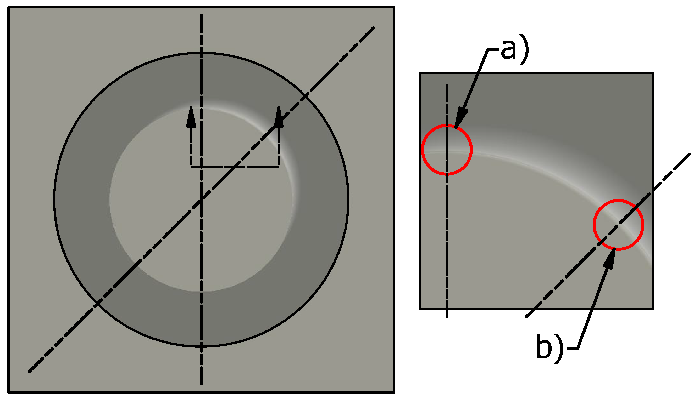
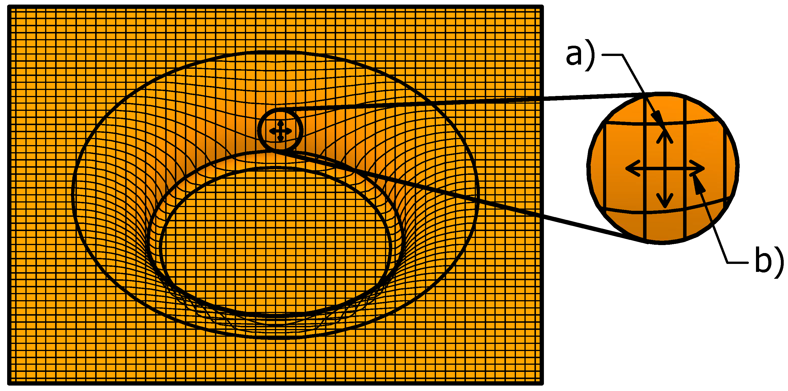
2.1.2. Toolpath Generation
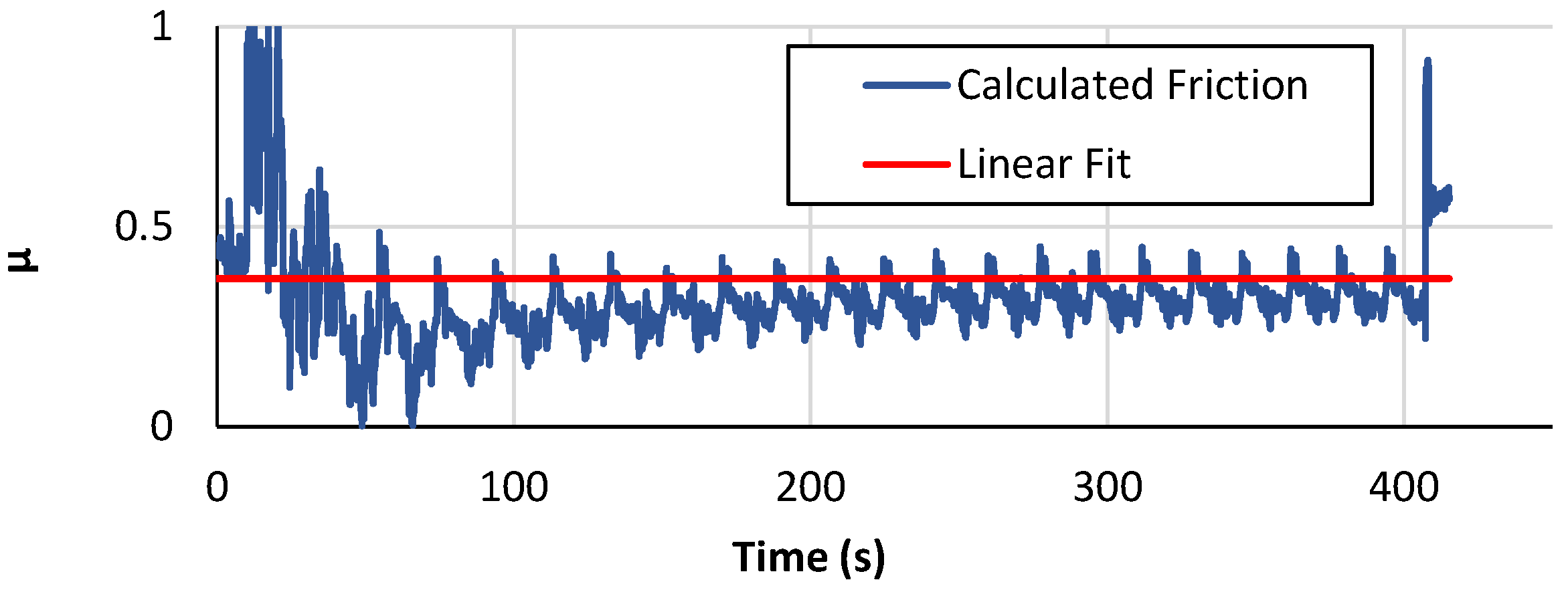
2.1.3. Friction Analysis
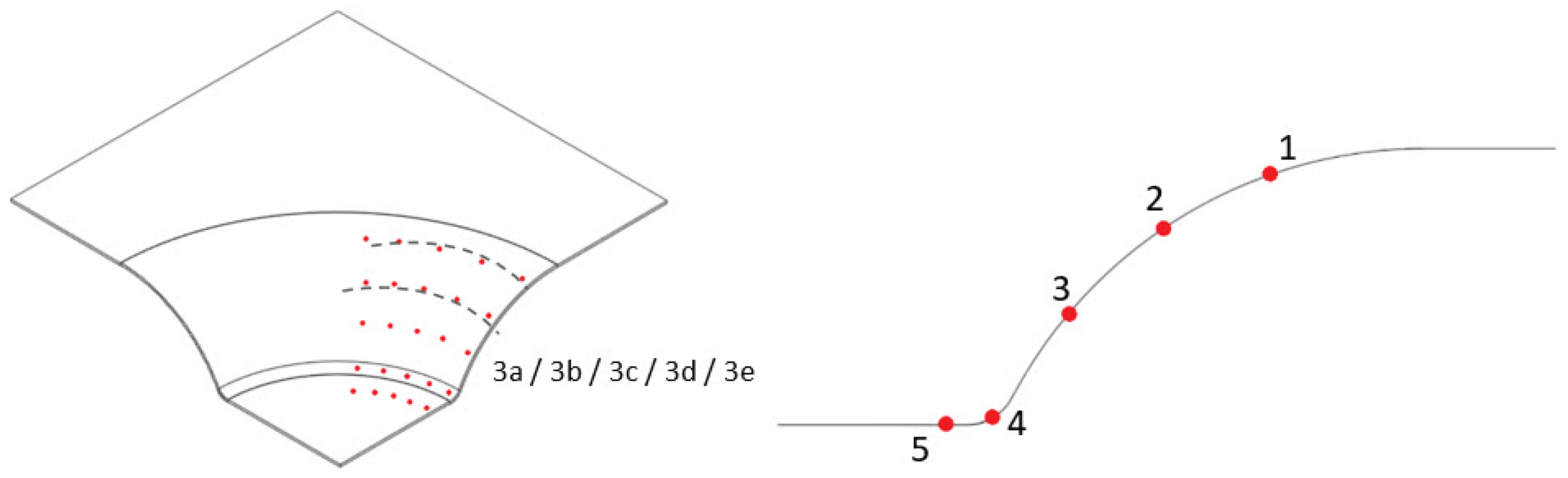
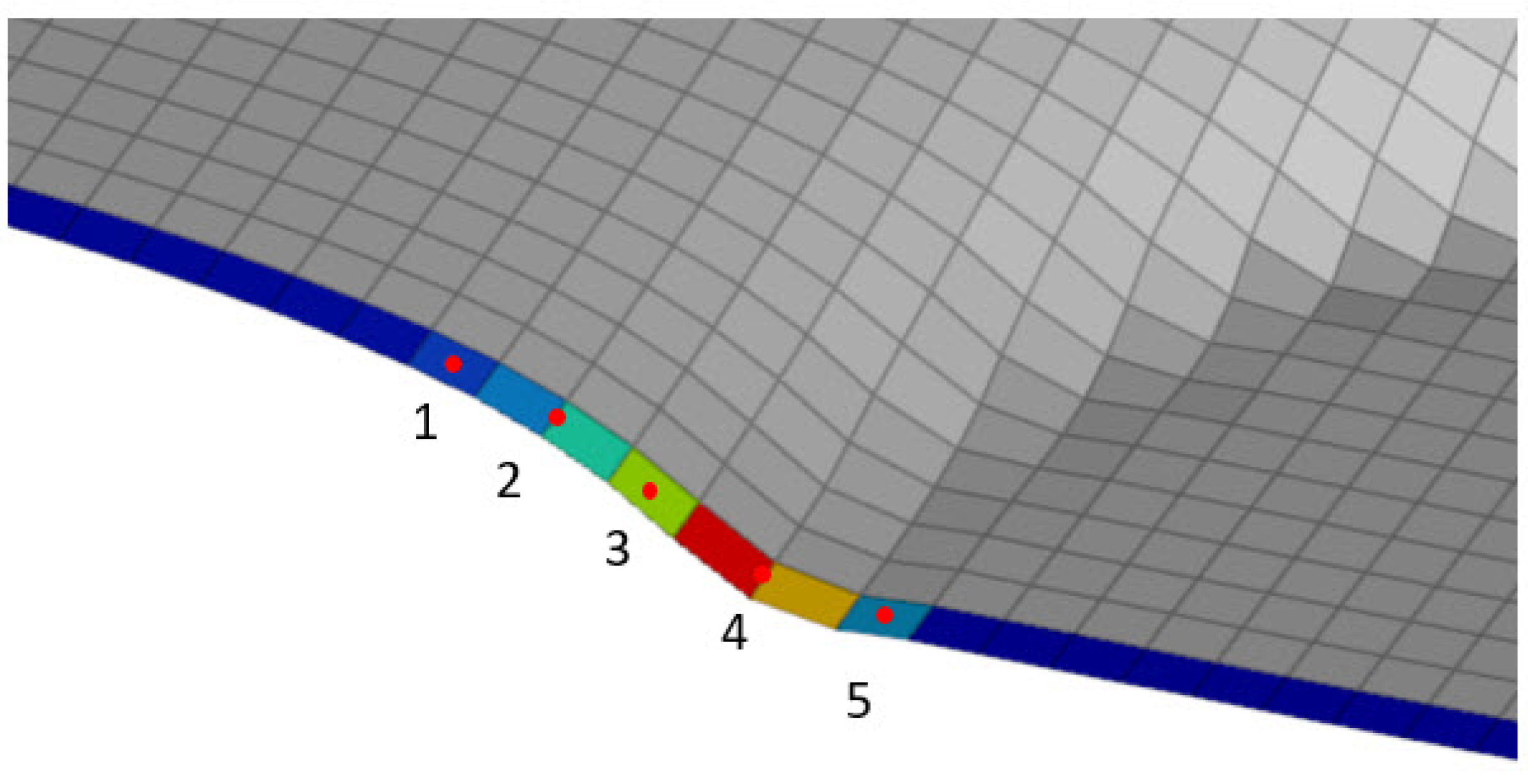
2.2. Strain Measurement
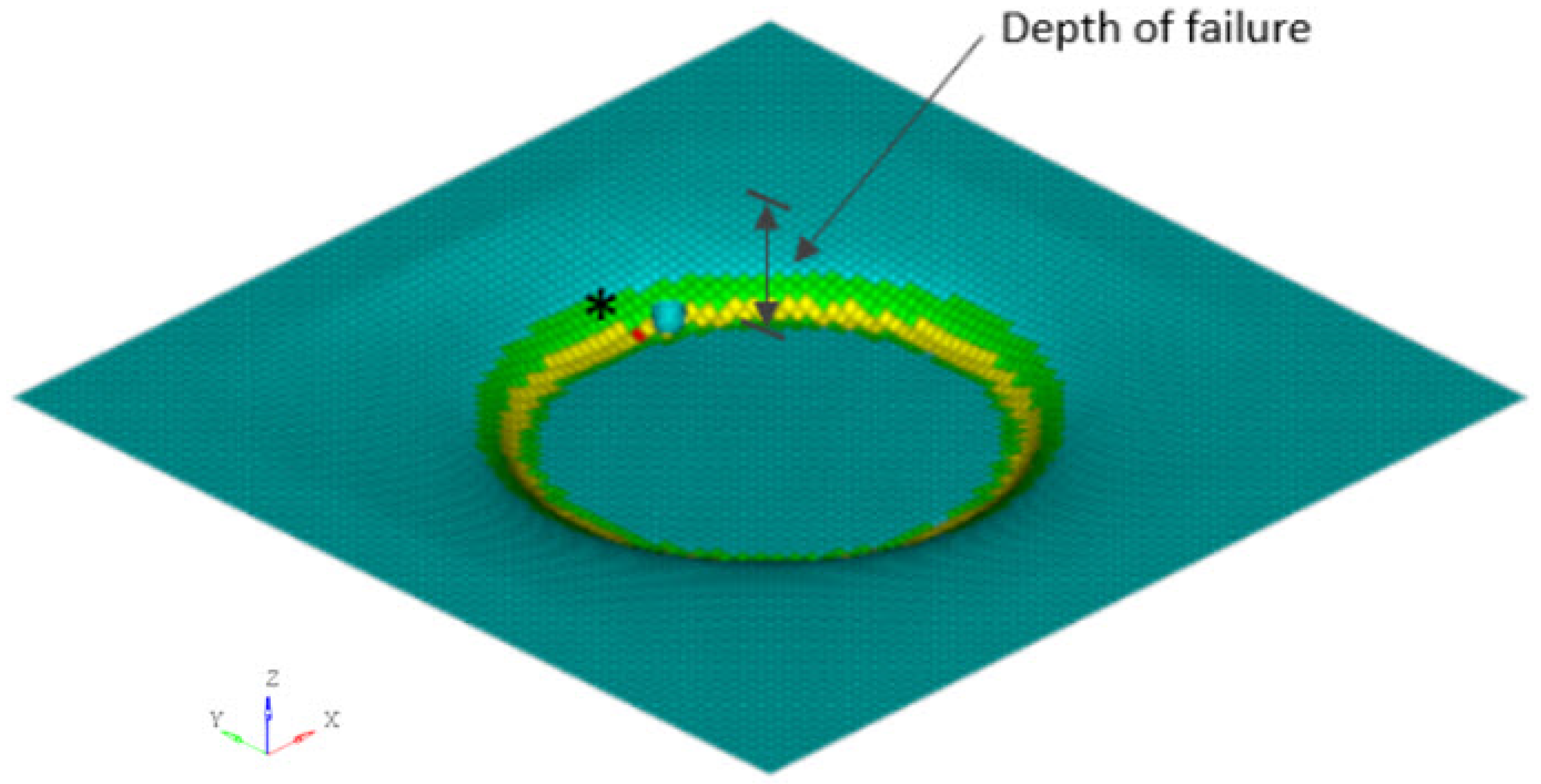
2.3. Thickness Measurement
3. Results
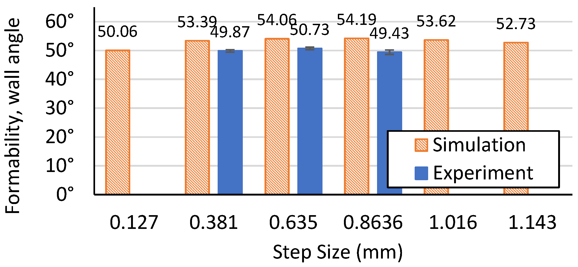
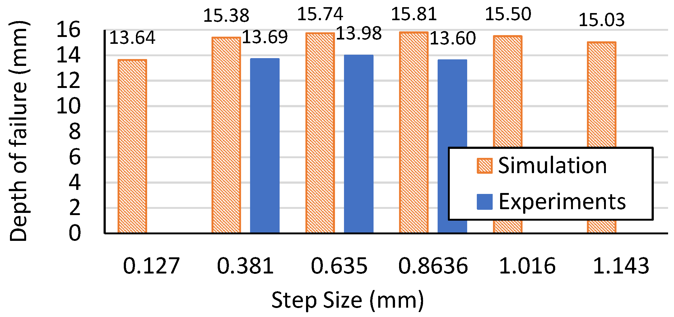
3.1. Formability
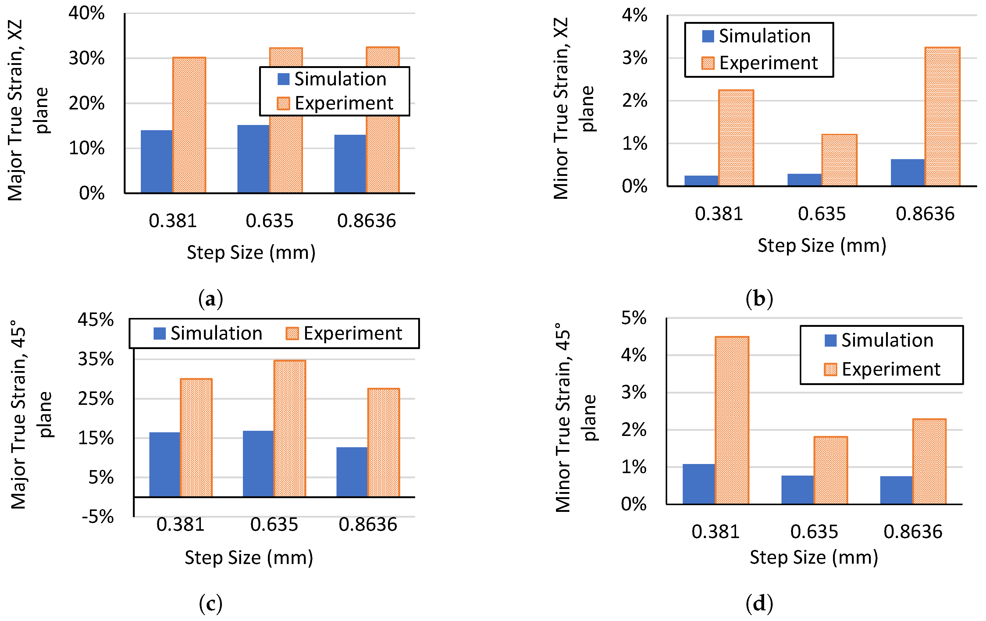
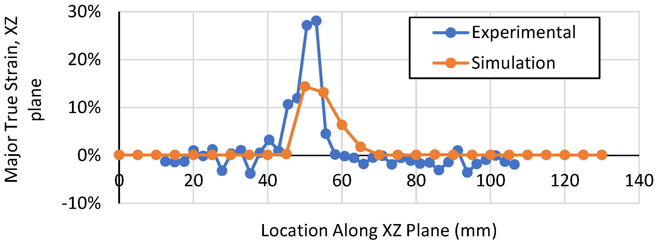
3.2. Maximum Strain
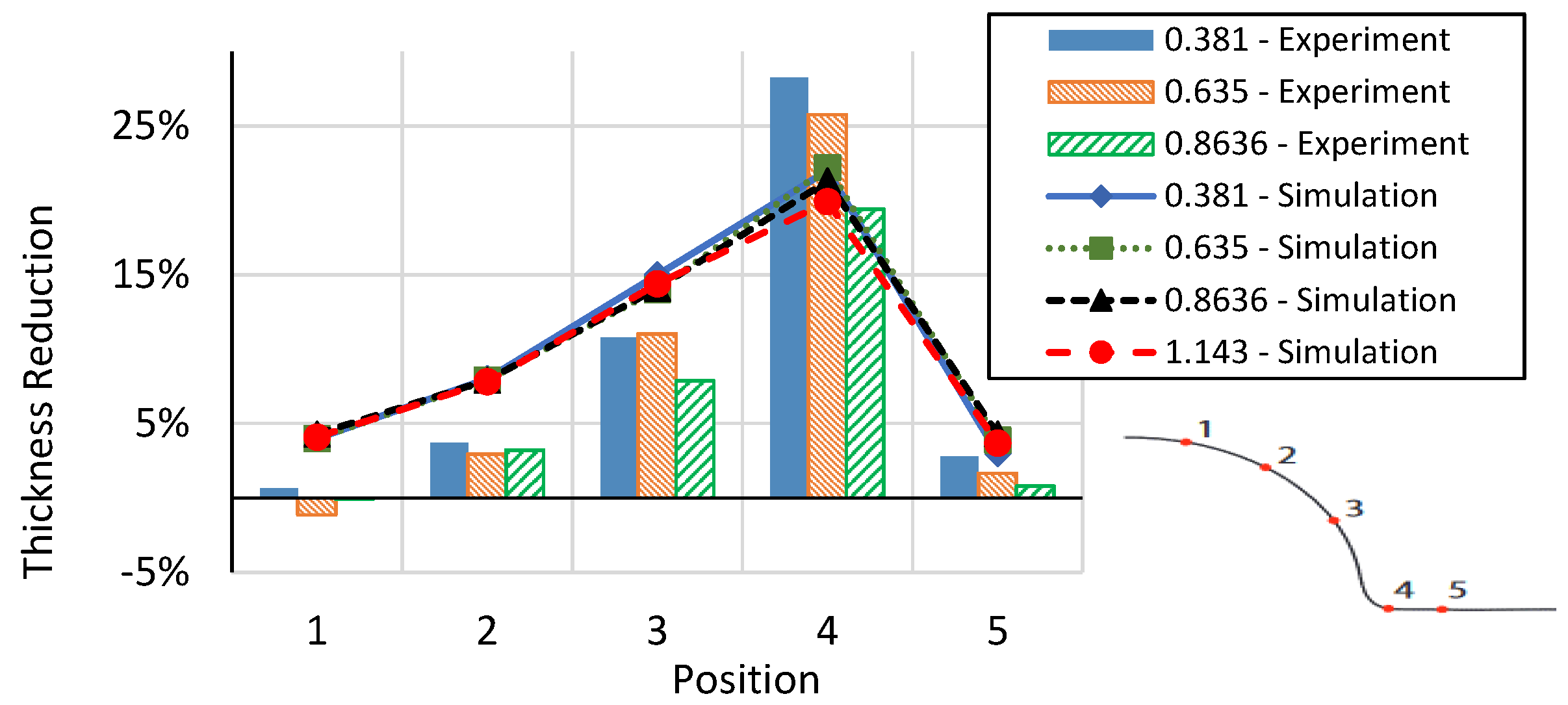
3.3. Thickness Reduction
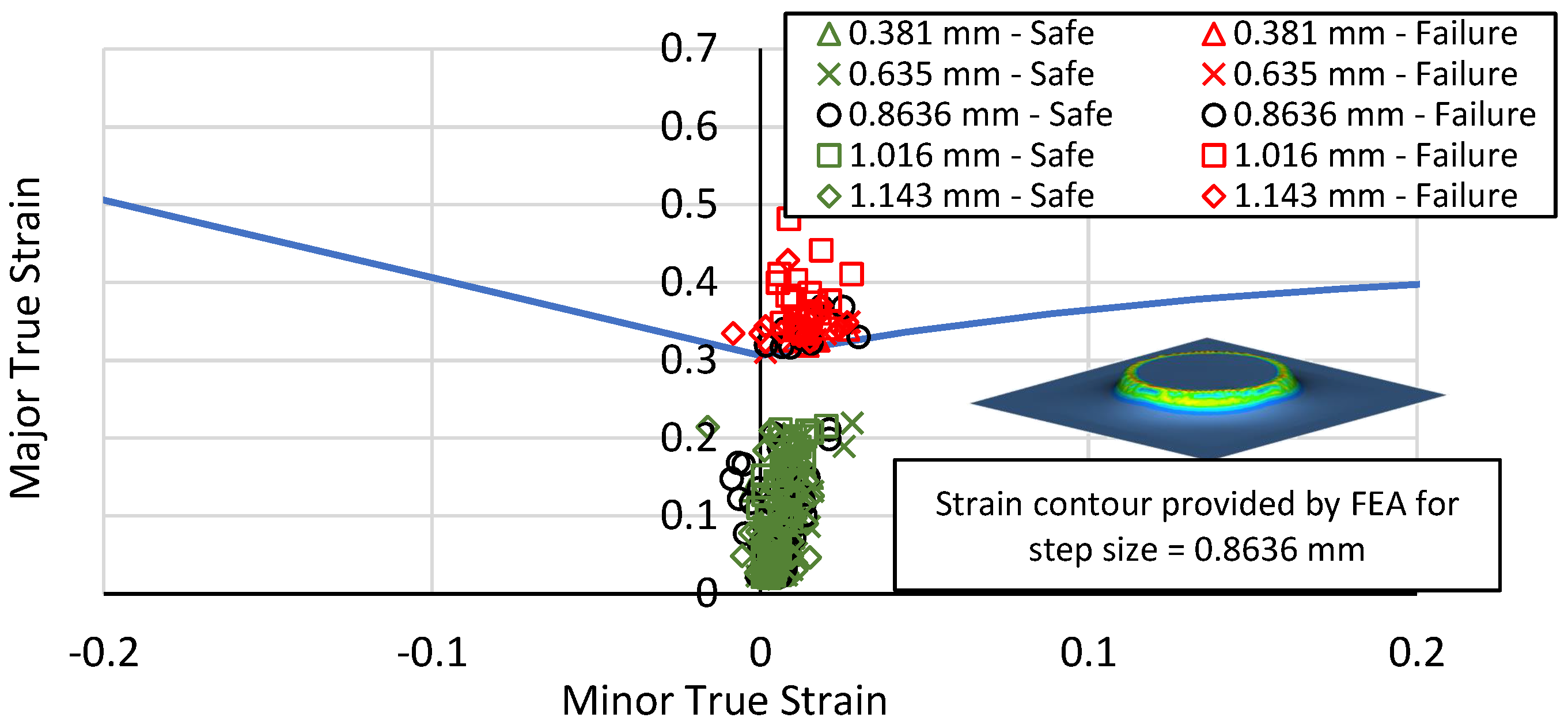
3.4. Forming Limit Diagram
4. Conclusions
Author Contributions
Funding
Data Availability Statement
Acknowledgments
Conflicts of Interest
References
- Kim, Y.H.; Park, J.J. Effect of process parameters on formability in incremental forming of sheet metal. J. Mater. Process. Technol. 2002, 130, 42–46. [Google Scholar] [CrossRef]
- Strano, M.; Sorrentino, L.; Carrino, L. Some issues about tools and friction in the negative dieless incremental forming process. In Proceedings of the Conference Metal Forming 2004, Krakow, Poland, 19–22 September 2004; pp. 345–350. [Google Scholar]
- Micari, F.; Ambrogio, G. A common shape for conducting incremental forming tests. In Proceedings of the 1st Incremental Forming Workshop, Saarbrücken, Germany, 9 June 2004; Volume 9. [Google Scholar]
- Micari, F. Single point incremental forming: Recent results. In Proceedings of the Seminar on Incremental Forming, Cambridge, UK, 22 October 2004; Volume 22. [Google Scholar]
- Hirt, G.; Junk, S.; Witulski, N. Incremental sheet forming: Quality evaluation and process simulation. In Proceedings of the 7th ICTP International Conference on Technology of Plasticity, Yokohama, Japan, 27 October–1 November 2002; pp. 925–930. [Google Scholar]
- Hagan, E.; Jeswiet, J. Analysis of surface roughness for parts formed by computer numerical controlled incremental forming. Proc. Inst. Mech. Eng. Part B J. Eng. Manuf. 2004, 218, 1307–1312. [Google Scholar] [CrossRef]
- Fan, G.; Gao, L. Numerical simulation and experimental investigation to improve the dimensional accuracy in electric hot incremental forming of Ti-6Al-4V titanium sheet. Int. J. Adv. Manuf. Technol. 2014, 72, 1133–1141. [Google Scholar] [CrossRef]
- Honarpisheh, M.; Abdolhoseini, M.J.; Amini, S. Experimental and numerical investigation of the hot incremental forming of Ti-6Al-4V sheet using electrical current. Int. J. Adv. Manuf. Technol. 2016, 83, 2027–2037. [Google Scholar] [CrossRef]
- Fan, G.; Gao, L. Mechanical property of Ti-6Al-4V sheet in one-sided electric hot incremental forming. Int. J. Adv. Manuf. Technol. 2014, 72, 989–994. [Google Scholar] [CrossRef]
- Ambrogio, G.; Filice, L.; Gagliardi, F. Formability of lightweight alloys by hot incremental sheet forming. Mater. Des. 2012, 34, 501–508. [Google Scholar] [CrossRef]
- Fan, G.; Sun, F.; Meng, X.; Gao, L.; Tong, G. Electric hot incremental forming of Ti-6Al-4V titanium sheet. Int. J. Adv. Manuf. Technol. 2010, 49, 941–947. [Google Scholar] [CrossRef]
- Fan, G.; Gao, L.; Hussain, G.; Wu, Z. Electric hot incremental forming: A novel technique. Int. J. Mach. Tools Manuf. 2008, 48, 1688–1692. [Google Scholar] [CrossRef]
- Adams, D.; Jeswiet, J. Single-point incremental forming of 6061-T6 using electrically assisted forming methods. Proc. Inst. Mech. Eng. Part B J. Eng. Manuf. 2014, 228, 757–764. [Google Scholar] [CrossRef]
- Xu, D.; Lu, B.; Cao, T.; Chen, J.; Long, H.; Cao, J. A comparative study on process potentials for frictional stir-and electric hot-assisted incremental sheet forming. Procedia Eng. 2014, 81, 2324–2329. [Google Scholar] [CrossRef]
- Shi, X.; Gao, L.; Khalatbari, H.; Xu, Y.; Wang, H. Electric hot incremental forming of low carbon steel sheet: Accuracy improvement. Int. J. Adv. Manuf. Technol. 2013, 68, 241–247. [Google Scholar] [CrossRef]
- Adams, D.W. Improvements on Single Point Incremental Forming Through Electrically Assisted Forming, Contact Area Prediction and Tool Development. Ph.D. Thesis, Queens University, Kingston, ON, Canada, 2013. [Google Scholar]
- Meier, H.; Magnus, C. Incremental sheet metal forming with direct resistance heating using two moving tools. In Key Engineering Materials; Trans Tech Publications Ltd.: Zürich, Switzerland, 2013; Volume 554, pp. 1362–1367. [Google Scholar]
- Grimm, T.J.; Ragai, I.; Roth, J.T. The Effects of Polarity and Current Path in Electrically Assisted Single Point Incremental Forming of 2024-T3 Aluminum. In Proceedings of the International Manufacturing Science and Engineering Conference, Los Angeles, CA, USA, 4–8 June 2017; Volume 1. Processes:V001T02A063. [Google Scholar] [CrossRef]
- Duflou, J.R.; Callebaut, B.; Verbert, J.; De Baerdemaeker, H. Laser assisted incremental forming: Formability and accuracy improvement. CIRP Ann.-Manuf. Technol. 2007, 56, 273–276. [Google Scholar] [CrossRef]
- Göttmann, A.; Diettrich, J.; Bergweiler, G.; Bambach, M.; Hirt, G.; Loosen, P.; Poprawe, R. Laser-assisted asymmetric incremental sheet forming of titanium sheet metal parts. Prod. Eng. 2011, 5, 263–271. [Google Scholar] [CrossRef]
- Taleb Araghi, B.; Göttmann, A.; Bergweiler, G.; Saeed-Akbari, A.; Bültmann, J.; Zettler, J.; Bambach, M.; Hirt, G. Investigation on incremental sheet forming combined with laser heating and stretch forming for the production of lightweight structures. In Key Engineering Materials; Trans Tech Publications Ltd.: Zürich, Switzerland, 2011; Volume 473, pp. 919–928. [Google Scholar]
- Mohammadi, A.; Vanhove, H.; Van Bael, A.; Duflou, J.R. Towards accuracy improvement in single point incremental forming of shallow parts formed under laser assisted conditions. Int. J. Mater. Form. 2016, 9, 339–351. [Google Scholar] [CrossRef]
- Al-Obaidi, A.; Kräusel, V.; Landgrebe, D. Hot single-point incremental forming assisted by induction heating. Int. J. Adv. Manuf. Technol. 2016, 82, 1163–1171. [Google Scholar] [CrossRef]
- Palumbo, G.; Brandizzi, M. Experimental investigations on the single point incremental forming of a titanium alloy component combining static heating with high tool rotation speed. Mater. Des. 2012, 40, 43–51. [Google Scholar] [CrossRef]
- Li, Y.; Liu, Z.; Daniel, W.J.T.; Meehan, P.A. Simulation and experimental observations of effect of different contact interfaces on the incremental sheet forming process. Mater. Manuf. Process. 2014, 29, 121–128. [Google Scholar] [CrossRef]
- Lu, B.; Fang, Y.; Xu, D.K.; Chen, J.; Ou, H.; Moser, N.H.; Cao, J. Mechanism investigation of friction-related effects in single point incremental forming using a developed oblique roller-ball tool. Int. J. Mach. Tools Manuf. 2014, 85, 14–29. [Google Scholar] [CrossRef]
- Vihtonen, L.; Puzik, A.; Katajarinne, T. Comparing two robot assisted incremental forming methods: Incremental forming by pressing and incremental hammering. Int. J. Mater. Form. 2008, 1, 1207–1210. [Google Scholar] [CrossRef]
- Schafer, T.; Schraft, R.D. Incremental sheet metal forming by industrial robots. Rapid Prototyp. J. 2005, 11, 278–286. [Google Scholar] [CrossRef]
- Puzik, A. Incremental sheet forming with a robot system for an industrial application. In Manufacturing Systems and Technologies for the New Frontier; Springer: Berlin/Heidelberg, Germany, 2008; pp. 421–424. [Google Scholar]
- Meier, H.; Buff, B.; Laurischkat, R.; Smukala, V. Increasing the part accuracy in dieless robot-based incremental sheet metal forming. CIRP Ann. 2009, 58, 233–238. [Google Scholar] [CrossRef]
- Kreimeier, D.; Buff, B.; Magnus, C.; Smukala, V.; Zhu, J. Robot-based incremental sheet metal forming–increasing the geometrical accuracy of complex parts. In Key Engineering Materials; Trans Tech Publications Ltd.: Zürich, Switzerland, 2011; Volume 473, pp. 853–860. [Google Scholar]
- Amini, S.; Gollo, A.H.; Paktinat, H. An investigation of conventional and ultrasonic-assisted incremental forming of annealed AA1050 sheet. Int. J. Adv. Manuf. Technol. 2017, 90, 1569–1578. [Google Scholar] [CrossRef]
- Vahdati, M.; Mahdavinejad, R.; Amini, S. Investigation of the ultrasonic vibration effect in incremental sheet metal forming process. Proc. Inst. Mech. Eng. Part B J. Eng. Manuf. 2017, 231, 971–982. [Google Scholar] [CrossRef]
- Cai, G.P.; Xing, C.W.; Jiang, Z.H.; Zhang, Z.K. Sheet Single point vibration incremental forming process simulation and analysis of process parameters. In Advanced Materials Research; Trans Tech Publications Ltd.: Zürich, Switzerland, 2012; Volume 430, pp. 74–78. [Google Scholar]
- Ziran, X.; Gao, L.; Hussain, G.; Cui, Z. The performance of flat end and hemispherical end tools in single-point incremental forming. Int. J. Adv. Manuf. Technol. 2010, 46, 1113–1118. [Google Scholar] [CrossRef]
- Grimm, T.J.; Ragai, I.; Roth, J.T. A Novel Modification to the Incremental Forming Process, Part 1: Multi-directional Tooling. Procedia Manuf. 2017, 10, 510–519. [Google Scholar] [CrossRef]
- Grimm, T.J.; Ragai, I.; Roth, J.T. A Novel Modification to the Incremental Forming Process, Part 2: Validation of the Multi-directional Tooling Method. Procedia Manuf. 2017, 10, 520–530. [Google Scholar] [CrossRef]
- Young, D.; Jeswiet, J. Wall thickness variations in single-point incremental forming. Proc. Inst. Mech. Eng. Part B J. Eng. Manuf. 2004, 218, 1453–1459. [Google Scholar] [CrossRef]
- Kim, T.J.; Yang, D.Y. Improvement of formability for the incremental sheet metal forming process. Int. J. Mech. Sci. 2000, 42, 1271–1286. [Google Scholar] [CrossRef]
- Liu, Z.; Daniel, W.J.T.; Li, Y.; Liu, S.; Meehan, P.A. Multi-pass deformation design for incremental sheet forming: Analytical modeling, finite element analysis and experimental validation. J. Mater. Process. Technol. 2014, 214, 620–634. [Google Scholar] [CrossRef]
- Malhotra, R.; Bhattacharya, A.; Kumar, A.; Reddy, N.V.; Cao, J. A new methodology for multi-pass single point incremental forming with mixed toolpaths. CIRP Ann.-Manuf. Technol. 2011, 60, 323–326. [Google Scholar] [CrossRef]
- Duflou, J.R.; Verbert, J.; Belkassem, B.; Gu, J.; Sol, H.; Henrard, C.; Habraken, A.M. Process window enhancement for single point incremental forming through multi-step toolpaths. CIRP Ann.-Manuf. Technol. 2008, 57, 253–256. [Google Scholar] [CrossRef]
- Verbert, J.; Belkassem, B.; Henrard, C.; Habraken, A.M.; Gu, J.; Sol, H.; Lauwers, B.; Duflou, J.R. Multi-Step toolpath approach to overcome forming limitations in single point incremental forming. Int. J. Mater. Form. 2008, 1, 1203–1206. [Google Scholar] [CrossRef]
- Grimm, T.J.; Ragai, I.; Roth, J.T. Utilization of Wavy Toolpath in Single-Point Incremental Forming. In Proceedings of the ASME 2018 International Mechanical Engineering Congress and Exposition, Pittsburgh, PA, USA, 9–15 November 2018; American Society of Mechanical Engineers: New York, NY, USA, 2018. [Google Scholar]
- Grimm, T.J.; Mears, L. Investigation of a radial toolpath in single point incremental forming. Procedia Manuf. 2020, 48, 215–222. [Google Scholar] [CrossRef]
- Hirt, G.; Junk, S.; Bambach, M.; Chouvalova, I. Process limits and material behaviour in incremental sheet forming with CNC-tools. In Materials Science Forum; Trans Tech Publications Ltd.: Zurich-Uetikon, Switzerland, 2003; Volume 426, pp. 3825–3830. [Google Scholar]
- Jeswiet, J.; Young, D. Forming limit diagrams for single-point incremental forming of aluminium sheet. Proc. Inst. Mech. Eng. Part B J. Eng. Manuf. 2005, 219, 359–364. [Google Scholar] [CrossRef]
- Filice, L.; Fratini, L.; Micari, F. Analysis of material formability in incremental forming. CIRP Ann.-Manuf. Technol. 2002, 51, 199–202. [Google Scholar] [CrossRef]
- Silva, M.B.; Skjødt, M.; Atkins, A.G.; Bay, N.; Martins, P.A.F. Single-point incremental forming and formability—Failure diagrams. J. Strain Anal. Eng. Des. 2008, 43, 15–35. [Google Scholar] [CrossRef]
- Ham, M.; Jeswiet, J. Forming limit curves in single point incremental forming. CIRP Ann.-Manuf. Technol. 2007, 56, 277–280. [Google Scholar] [CrossRef]
- Eyckens, P.; Belkassem, B.; Henrard, C.; Gu, J.; Sol, H.; Habraken, A.M.; Duflou, J.R.; Van Bael, A.; Van Houtte, P. Strain evolution in the single point incremental forming process: Digital image correlation measurement and finite element prediction. Int. J. Mater. Form. 2011, 4, 55–71. [Google Scholar] [CrossRef]
- Huang, Y.; Wang, Y.J.; Cao, J.; Li, M. Prediction of forming limit in single point incremental forming with the ductile fracture criterion. In Proceedings of the ASME 2007 International Manufacturing Science and Engineering Conference, Atlanta, GA, USA, 15–18 October 2007; American Society of Mechanical Engineers: New York, NY, USA, 2007; pp. 929–934. [Google Scholar]
- Nguyen, D.T.; Kim, Y.S. A numerical study on establishing the forming limit curve and indicating the formability of complex shape in incremental sheet forming process. Int. J. Precis. Eng. Manuf. 2013, 14, 2087–2093. [Google Scholar] [CrossRef]
- Arshad, S. A Study of Forming Parameters, Forming Limits and Part Accuracy of Aluminium 2024, 6061 and 7475 Alloys. Ph.D. Thesis, KTH Royal Institute of Technology, Stockholm, Sweden, 2012. [Google Scholar]
- Jeswiet, J.; Micari, F.; Hirt, G.; Bramley, A.; Duflou, J.; Allwood, J. Asymmetric single point incremental forming of sheet metal. CIRP Ann.-Manuf. Technol. 2005, 54, 88–114. [Google Scholar] [CrossRef]
- Hussain, G.; Gao, L.; Hayat, N.; Dar, N.U. The formability of annealed and pre-aged AA-2024 sheets in single-point incremental forming. Int. J. Adv. Manuf. Technol. 2010, 46, 543–549. [Google Scholar] [CrossRef]
- Ham, M.; Jeswiet, J. Single point incremental forming and the forming criteria for AA3003. CIRP Ann.-Manuf. Technol. 2006, 55, 241–244. [Google Scholar] [CrossRef]
- Kurra, S.; Regalla, S.P. Experimental and numerical studies on formability of extra-deep drawing steel in incremental sheet metal forming. J. Mater. Res. Technol. 2014, 3, 158–171. [Google Scholar] [CrossRef]
- Ghazanfari, A.; Soleimani, S.S.; Keshavarzzadeh, M.; Habibi, M.; Assempuor, A.; Hashemi, R. Prediction of FLD for sheet metal by considering through-thickness shear stresses. Mech. Based Des. Struct. Mach. 2020, 48, 755–772. [Google Scholar] [CrossRef]
- Khan, M.S.; Coenen, F.; Dixon, C.; El-Salhi, S.; Penalva, M.; Rivero, A. An intelligent process model: Predicting springback in single point incremental forming. Int. J. Adv. Manuf. Technol. 2015, 76, 2071–2082. [Google Scholar] [CrossRef]
- Arfa, H.; Bahloul, R.; BelHadjSalah, H. Finite element modelling and experimental investigation of single point incremental forming process of aluminum sheets: Influence of process parameters on punch force monitoring and on mechanical and geometrical quality of parts. Int. J. Mater. Form. 2013, 6, 483–510. [Google Scholar] [CrossRef]
- He, S.; Van Bael, A.; Van Houtte, P.; Duflou, J.R.; Szekeres, A.; Henrard, C.; Habraken, A.M. Finite element modeling of incremental forming of aluminum sheets. In Advanced Materials Research; Trans Tech Publications Ltd.: Zürich, Switzerland, 2005; Volume 6, pp. 525–532. [Google Scholar]
- Salem, E.; Shin, J.; Nath, M.; Banu, M.; Taub, A.I. Investigation of thickness variation in single point incremental forming. Procedia Manuf. 2016, 5, 828–837. [Google Scholar] [CrossRef]
- Senthil, R.; Gnanavelbabu, A. Numerical analysis on formability of AZ61A magnesium alloy by incremental forming. Procedia Eng. 2014, 97, 1975–1982. [Google Scholar] [CrossRef]
- Hussain, G.; Gao, L.; Hayat, N.; Ziran, X. A new formability indicator in single point incremental forming. J. Mater. Process. Technol. 2009, 209, 4237–4242. [Google Scholar] [CrossRef]
- Benedetti, M.; Fontanari, V.; Monelli, B.; Tassan, M. Single-point incremental forming of sheet metals: Experimental study and numerical simulation. Proc. Inst. Mech. Eng. Part B J. Eng. Manuf. 2017, 231, 301–312. [Google Scholar] [CrossRef]
- Esmaeilpour, R.; Pourboghrat, F.; Kim, H.; Park, T. Finite Element Analysis of Single Point Incremental Forming (SPIF) of Aluminum 7075 Using Different Types of Toolpath. IOP Conf. Ser. Mater. Sci. Eng. 2019, 521, 012012. [Google Scholar] [CrossRef]
- Li, Q.M.; Yi, Z.W.; Liu, Y.Q.; Tang, X.F.; Jiang, W.; Li, H.J. Explicit Analysis of Sheet Metal Forming Processes Using Solid-Shell Elements. Metals 2022, 12, 52. [Google Scholar] [CrossRef]
- Grimm, T.J.; Mears, L. Numerical Determination of Unconstrained Area Effect on Springback in Incremental Forming of 5052-H32 Aluminum. In Proceedings of the ASME 2019 International Mechanical Engineering Congress and Exposition, Salt Lake City, UT, USA, 11–14 November 2019; American Society of Mechanical Engineers Digital Collection: New York, NY, USA, 2019. [Google Scholar]
- Rice, R.C.; Jackson, J.L.; Bakuckas, J.; Thompson, S. Metallic Materials Properties Development and Standardization (MMPDS), Scientific Report DOT/FAA/AR-MMPDS-01; U.S. Department of Transportation—Federal Aviation Administration—Office of Aviation Research: Washington, DC, USA.
- Kaufman, J.G. Properties of Aluminum Alloys: Tensile, Creep, and Fatigue Data at High and Low Temperatures; ASM International: Almere, The Netherlands, 1999. [Google Scholar]
- Bauccio, M. ASM Metals Reference Book; ASM International: Almere, The Netherlands, 1993. [Google Scholar]
- ASM International Handbook Committee. Properties and selection: Nonferrous alloys and special-purpose materials. ASM Int. 1992, 2, 1143–1144. [Google Scholar]


| Feed rate ↓ [1] | Formability ↑ |
| Tool size ↑ [1] | |
| Friction ↓ [1,2] | |
| Tool rotation ↑ [3] | |
| Step size ↓ [4,5,6] |
| Step Size (mm) | Feed Rate (mm/min) | Tool Radius (mm) | Formability |
|---|---|---|---|
| 0.381 | 3810 | 4.7625 | 67.9° |
| 0.635 | 67.6° | ||
| 0.8636 | 67.3° | ||
| 1.143 | 67.0° |
Disclaimer/Publisher’s Note: The statements, opinions and data contained in all publications are solely those of the individual author(s) and contributor(s) and not of MDPI and/or the editor(s). MDPI and/or the editor(s) disclaim responsibility for any injury to people or property resulting from any ideas, methods, instructions or products referred to in the content. |
© 2023 by the authors. Licensee MDPI, Basel, Switzerland. This article is an open access article distributed under the terms and conditions of the Creative Commons Attribution (CC BY) license (https://creativecommons.org/licenses/by/4.0/).
Share and Cite
Grimm, T.J.; Colombini, F.; Ragai, I. Numerical Investigation of Step Size Effect on Formability of 2024-T3 Aluminum in Incremental Forming. J. Manuf. Mater. Process. 2023, 7, 70. https://doi.org/10.3390/jmmp7020070
Grimm TJ, Colombini F, Ragai I. Numerical Investigation of Step Size Effect on Formability of 2024-T3 Aluminum in Incremental Forming. Journal of Manufacturing and Materials Processing. 2023; 7(2):70. https://doi.org/10.3390/jmmp7020070
Chicago/Turabian StyleGrimm, Tyler J., Filipe Colombini, and Ihab Ragai. 2023. "Numerical Investigation of Step Size Effect on Formability of 2024-T3 Aluminum in Incremental Forming" Journal of Manufacturing and Materials Processing 7, no. 2: 70. https://doi.org/10.3390/jmmp7020070
APA StyleGrimm, T. J., Colombini, F., & Ragai, I. (2023). Numerical Investigation of Step Size Effect on Formability of 2024-T3 Aluminum in Incremental Forming. Journal of Manufacturing and Materials Processing, 7(2), 70. https://doi.org/10.3390/jmmp7020070