
Tensile Strength and Microstructure of Rotary Friction-Welded Carbon Steel and Stainless Steel Joints

 ,
,
Abstract
:1. Introduction
2. Materials and Methods
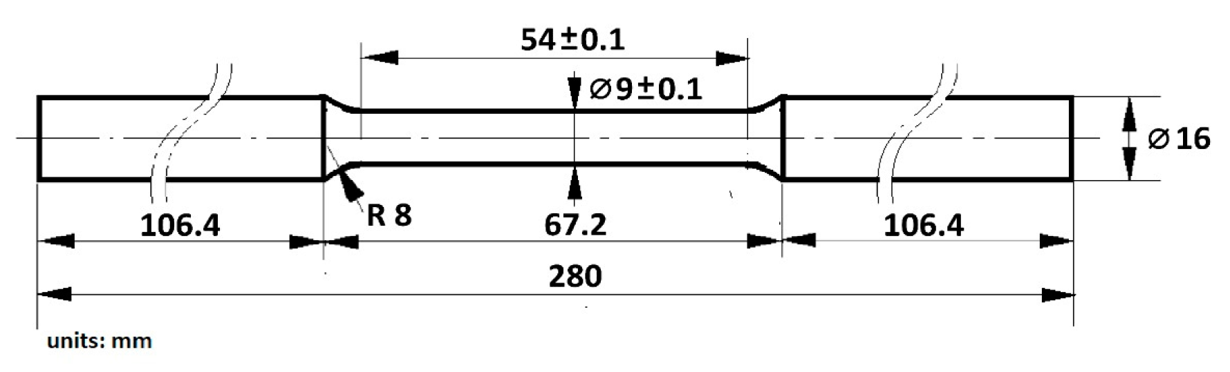
2.1. Materials
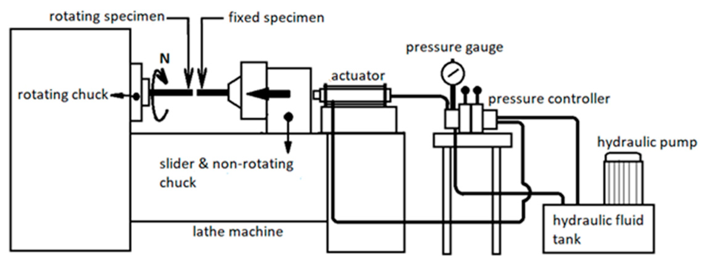
2.2. Experiment Setting and Procedure
2.3. Microstructure Analysis
2.4. Tensile Test
3. Results and Discussion
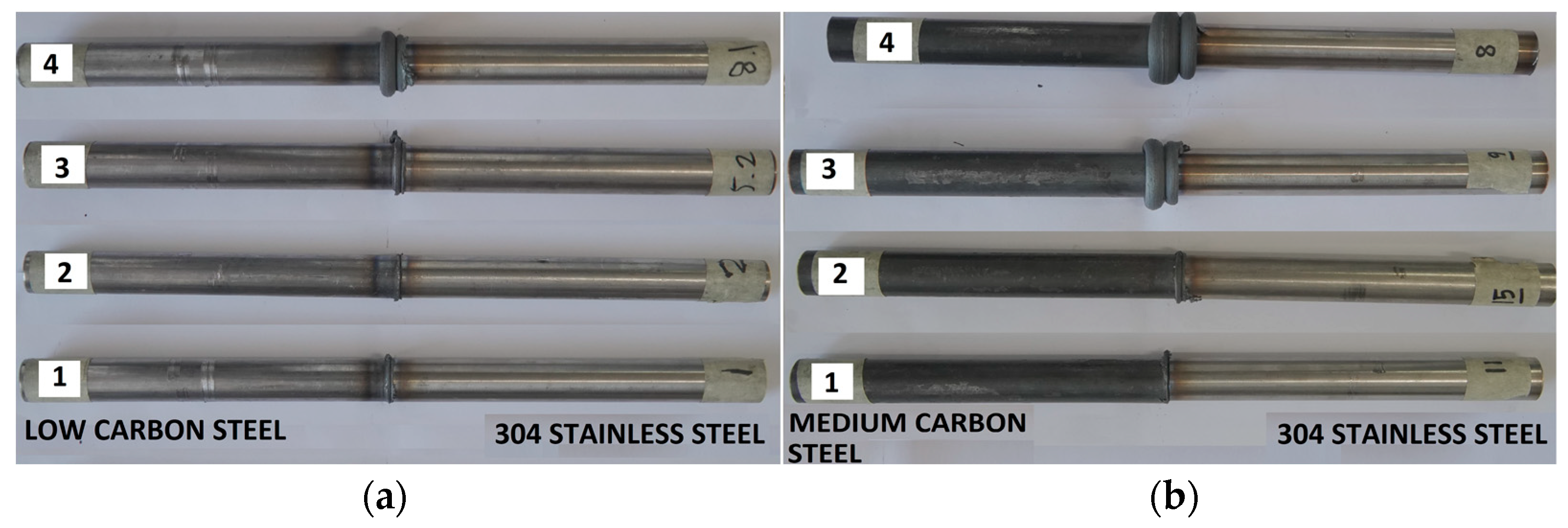
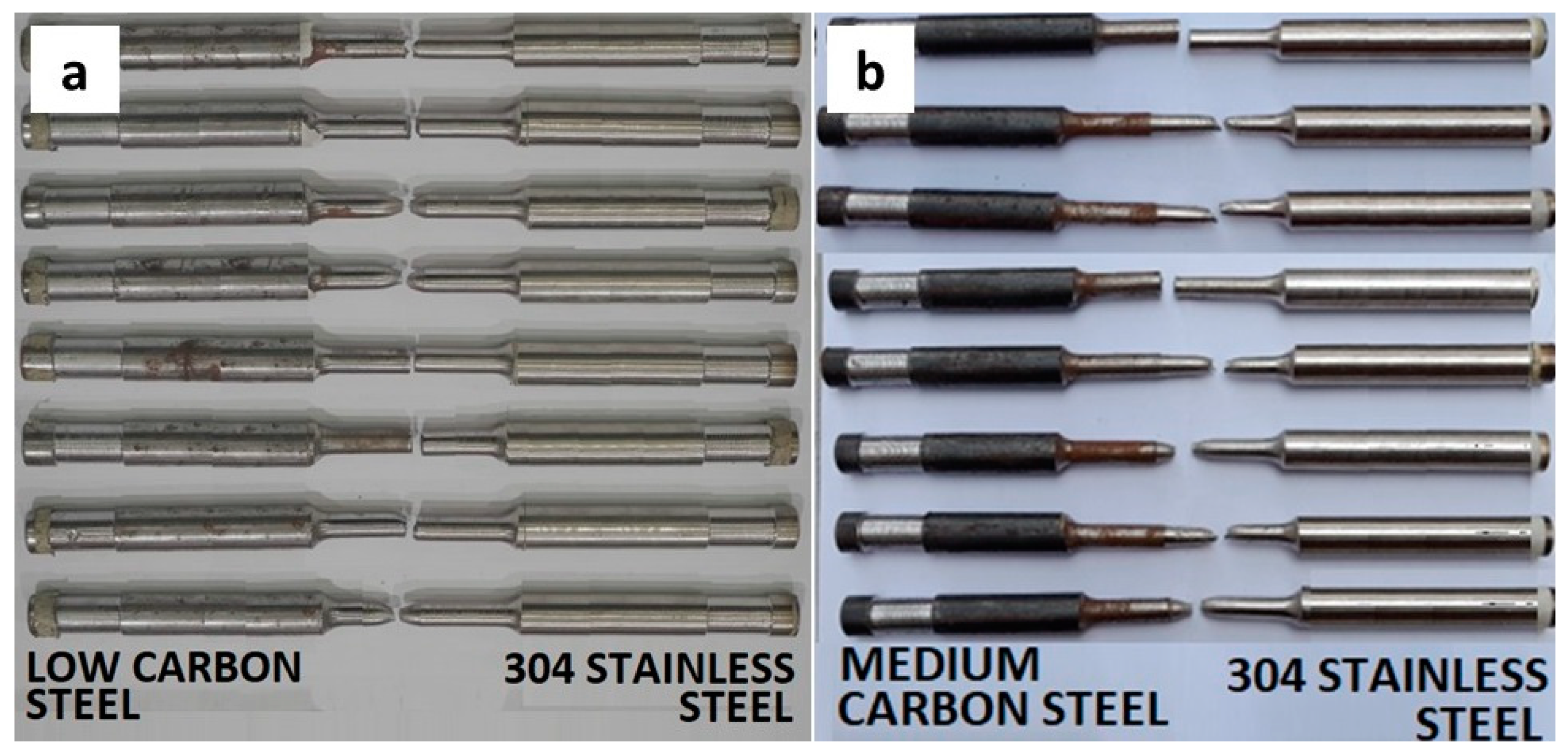
3.1. Visual Observation
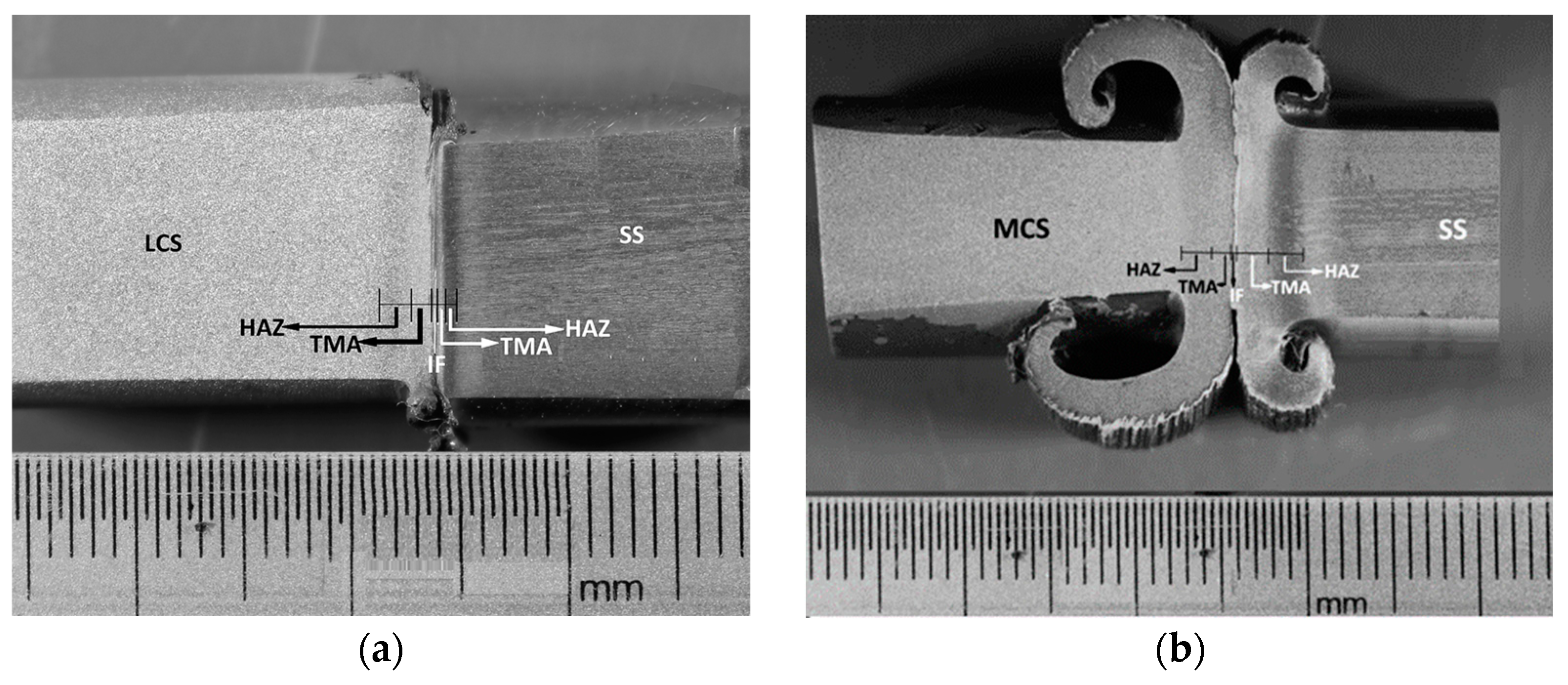
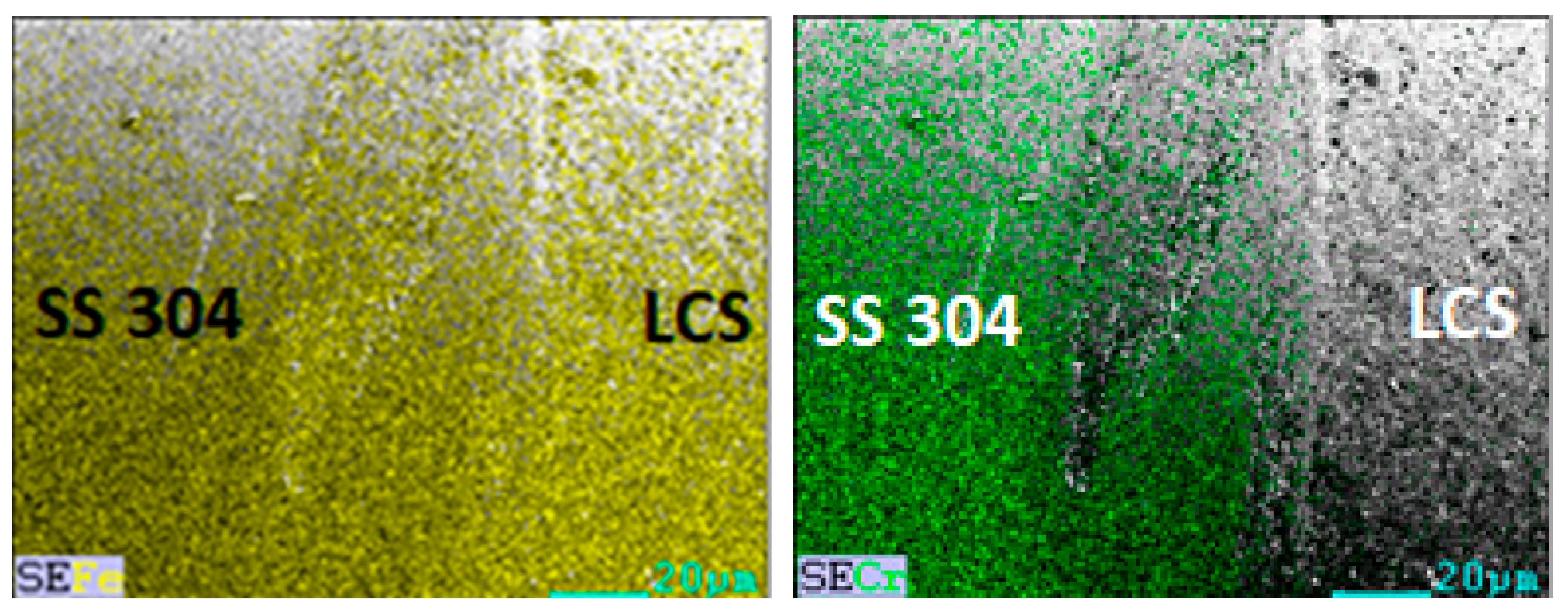
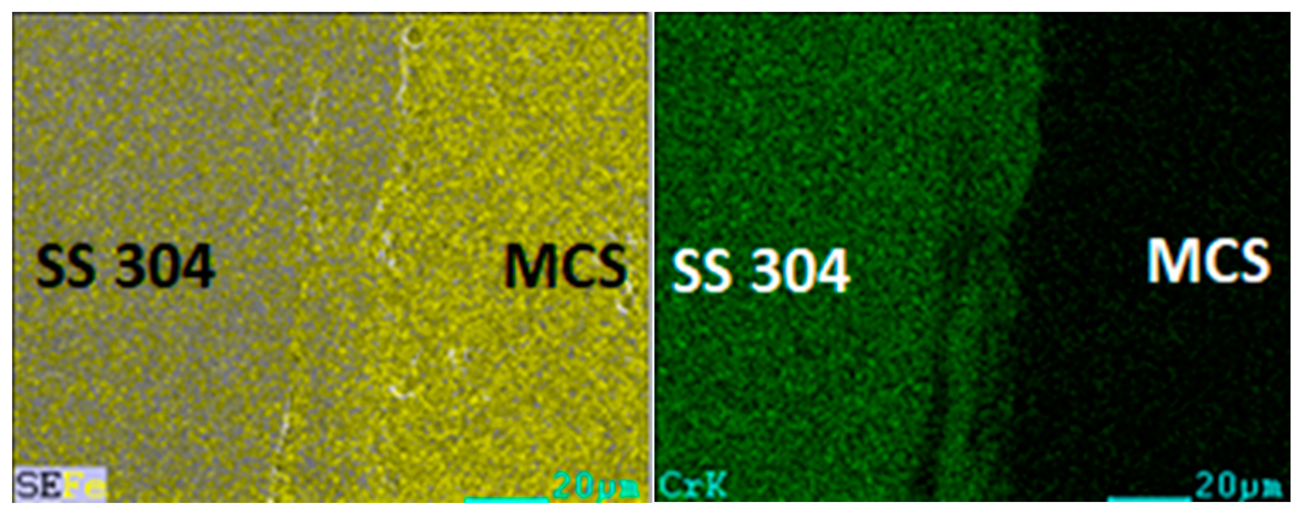
3.2. Microstructure of the Joint
3.3. Tensile Strength
3.4. Taguchi Analysis and Optimization
4. Conclusions
Author Contributions
Funding
Data Availability Statement
Conflicts of Interest
References
- Mvola, B.; Kah, P.; Martikainen, J. Welding of dissimilar non-ferrous metals by GMAW processes. Int. J. Mech. Mater. Eng. 2014, 9, 119. [Google Scholar] [CrossRef] [Green Version]
- Karim, A.; Park, Y.-D. A Review on Welding of Dissimilar Metals in Car Body Manufacturing. J. Weld. Join. 2020, 38, 8–23. [Google Scholar] [CrossRef] [Green Version]
- Chaudhari, R.; Loharkar, P.K.; Ingle, A. Applications and challenges of arc welding methods in dissimilar metal joining. IOP Conf. Ser. Mater. Sci. Eng. 2020, 810, 012006. [Google Scholar] [CrossRef]
- Zeng, H.; Zhang, Y.; Zhou, J.; Sun, D.; Li, H. Research Progress of Fusion Welding Techniques for Steel to Other Metals. Am. J. Mech. Mater. Eng. 2022, 6, 6–9. [Google Scholar] [CrossRef]
- Kah, P.; Shrestha, M.; Martikainen, J. Trends in Joining Dissimilar Metals by Welding. Appl. Mech. Mater. 2014, 440, 269–276. [Google Scholar]
- Vyas, H.D.; Mehta, K.P.; Badheka, V.; Doshi, B. Friction welding of dissimilar joints copper-stainless steel pipe consist of 0.06 wall thickness to pipe diameter ratio. J. Manuf. Process. 2021, 68, 1176–1190. [Google Scholar] [CrossRef]
- Shanjeevi, C.; Satish Kumar, S.; Sathiya, P. Evaluation of Mechanical and Metallurgical Properties of Dissimilar Materials by Friction Welding. Procedia Eng. 2013, 64, 1514–1523. [Google Scholar] [CrossRef] [Green Version]
- Zhao, S.; Wang, M.; Kou, S.; Jia, Z.; Wang, W.; Li, Q.; Luo, G.N. Realization of ODS-Cu/T91 Tube-to-tube Joining with Rotary Friction Welding. Fusion Eng. Des. 2020, 158, 111699. [Google Scholar] [CrossRef]
- Wang, M.; Zhao, S.; Wang, W.; Li, Q.; Luo, G.-N. Preliminary results of CuCrZr/316L tube-to-tube junctions fabricated with rotary friction welding. Fusion Eng. Des. 2019, 148, 111275. [Google Scholar] [CrossRef]
- Shanjeevi, C.; Arputhabalan, J.; Dutta, R. Pradeep Investigation on the Effect of Friction Welding Parameters on Impact Strength in Dissimilar Joints. IOP Conf. Ser. Mater. Sci. Eng. 2017, 197, 012069. [Google Scholar] [CrossRef] [Green Version]
- Karabey, Ö.; Akkuş, A. Effect of Welding Parameters on Axial Shortening in Continuous Friction Welded Inconel 718 Superalloy and AISI 316L Stainless Steel. Eur. J. Sci. Technol. 2022, 34, 311–316. [Google Scholar] [CrossRef]
- Anitha, P.; Majumder, M.C.; Saravanan, V.; Rajakumar, S. Effect of Burn-Off Length for Friction Welded Dissimilar Joints of Inconel 718 and SS410. J. Adv. Mech. Eng. Sci. 2018, 4, 30–37. [Google Scholar] [CrossRef]
- Kumar, R.; Balasubramanian, M. Application of response surface methodology to optimize process parameters in friction welding of Ti–6Al–4V and SS304L rods. Trans. Nonferrous Met. Soc. China 2015, 25, 3625–3633. [Google Scholar] [CrossRef]
- Muralimohan, C.H.; Muthupandi, V.; Sivaprasad, K. Properties of Friction Welding Titanium-Stainless Steel Joints with a Nickel Interlayer. Procedia Mater. Sci. 2014, 5, 1120–1129. [Google Scholar] [CrossRef] [Green Version]
- Cheepu, M.; Che, W.S. Friction Welding of Titanium to Stainless Steel Using Al Interlayer. Trans. Indian Inst. Met. 2019, 72, 1563–1568. [Google Scholar] [CrossRef]
- Alves, E.P.; Toledo, R.C.; Botter, F.G.; An, C.Y. Experimental Thermal Analysis in Rotary Friction Welding of Dissimilar Materials. J. Aerosp. Technol. Manag. 2019, 11, 1068. [Google Scholar] [CrossRef]
- Vishnoi, M.; Kumar, V.A.N.; Murugan, S.S. Friction welding of stainless steel-aluminum alloy and optimization of different parameters using Taguchi-L8 array method. J. Mech. Mech. Eng. 2017, 4, 1–10. [Google Scholar]
- Dong, H.; Yang, J.; Li, Y.; Xia, Y.; Hao, X.; Li, P.; Sun, D.; Hu, J.; Zhou, W.; Lei, M. Evolution of interface and tensile properties in 5052 aluminum alloy/304 stainless steel rotary friction welded joint after post-weld heat treatment. J. Manuf. Process. 2020, 51, 142–150. [Google Scholar] [CrossRef]
- Allali, A.; Aissani, M.; Mesrati, N.; Othmani, B.; Medkour, M.; Boukhadouni, I.; Khiali, A. Experimental, mechanical characterizations of friction welding of steel and aluminum joints. J. Adv. Manuf. Eng. 2020, 1, 9–15. [Google Scholar]
- Khidhir, G.I.; Baban, S.A. Efficiency of dissimilar friction welded 1045 medium carbon steel and 316L austenitic stainless-steel joints. J. Mater. Res. Technol. 2019, 8, 1926–1932. [Google Scholar] [CrossRef]
- Nasution, A.K.; Gustami, H.; Suprastio, S.; Fadillah, M.A.; Octavia, J.; Saidin, S. Potential use of Friction Welding for Fabricating Semi-Biodegradable Bone Screws. Int. J. Autom. Mech. Eng. 2022, 19, 9660–9667. [Google Scholar] [CrossRef]
- Hernández-Leos, R.; Pérez-Quiroz, J.T.; Martínez, M.; Torres, J.; Castañeda, F.; Morales, J.; Antaño, R. Corrosion Evaluation of the Welded Zone between Carbon Steel and Stainless Steel Embedded in Concrete and Exposed to a Marine-Like Environment. Int. J. Electrochem. Sci. 2019, 14, 5690–5706. [Google Scholar] [CrossRef]
- Lee, S.H. A Hot Cracking on Dissimilar Metal Weld between A106Gr.B and A312 TP316L with Buttering ERNiCr-3. Metals 2019, 9, 533. [Google Scholar] [CrossRef]
- Khdir, Y.K.; Kako, S.A.; Gardi, R.H. Study of Welding Dissimilar Metals—Low-carbon Steel AISI 1018 and Austenitic Stainless Steel AISI 304. Polytech. J. 2020, 10, 1–5. [Google Scholar] [CrossRef]
- Geng, P.; Qin, G.; Zhou, J. Numerical and experimental investigation on friction welding of austenite stainless steel and middle carbon steel. J. Manuf. Process. 2019, 47, 83–97. [Google Scholar] [CrossRef]
- Alza, V.A. Rotational friction welding in dissimilar steels AISI 1018-AISI 2225: Effects on hardness, fatigue and microstructure. IOSR J. Mech. Civ. Eng. 2022, 19, 37–39. [Google Scholar]
- Winiczenko, R. Effect of friction welding parameters on the tensile strength and microstructural properties of dissimilar AISI 1020-ASTM A536 joints. Int. J. Adv. Manuf. Technol. 2016, 84, 941–955. [Google Scholar] [CrossRef] [Green Version]
- Paventhan, R.; Lakshminarayanan, P.R.; Balasubramanian, V. Optimization of Friction Welding Process Parameters for Joining Carbon Steel and Stainless Steel. J. Iron Steel Res. Int. 2012, 19, 66–71. [Google Scholar] [CrossRef]
- Akhil, V.; Charles, M.M. An investigation of mechanical and metallurgical properties of friction welded steel joint. Int. J. Innov. Sci. Res. Technol. 2017, 2, 265–271. [Google Scholar]
- Yohanes, Y.; Abdurrahman, R.; Ridwan, A. Finite element study on rotary friction welding process for mild steel. IOP Conf. Ser. Mater. Sci. Eng. 2019, 620, 012111. [Google Scholar] [CrossRef]
- Dawood, A.B.; Butt, S.I.; Hussain, G.; Siddiqui, M.A.; Maqsood, A.; Zhang, F. Thermal Model of Rotary Friction Welding for Similar and Dissimilar Metals. Metals 2017, 7, 224. [Google Scholar] [CrossRef] [Green Version]
- Salih, F.I.; Dawood, A.S.; Hamid, A.A. Effects of Key Processing Parameters of Continuous Drive Rotary Friction Welding on Thermal Characteristics of Similar and Dissimilar Joints. Al-Rafidain Eng. J. 2022, 27, 116–126. [Google Scholar] [CrossRef]
- Uranga, P.; Rodríguez-Ibabe, J.M. Thermomechanical Processing of Steels. Metals 2020, 10, 641. [Google Scholar] [CrossRef]
- Roy, R.K. A Primer on The Taguchi Method; Society of Manufacturing Engineers (SME): Southfield, MI, USA, 2010. [Google Scholar]
- Belavendram, N. Quality by Design: Taguchi Techniques for Industrial Experimentation; Prentice Hall: New York, NY, USA, 1995. [Google Scholar]
- ASTM E8/E8M-22; Standard Test Methods for Tension Testing of Metallic Materials. ASTM International: West Conshohocken, PA, USA, 2016.
- Purwanto, H. Interface Structure in Friction Welded Joints between Stainless Steel 304 and Mild Carbon Steel. J. Chem. Process Mater. Technol. 2022, 1, 8–14. [Google Scholar] [CrossRef]
- Kantumuchu, V.C.; Cheepu, M.M. The Influence of Friction Time on the Joint Interface and Mechanical Properties in Dissimilar Friction Welds. J. Met. Mater. Res. 2022, 5, 4209. [Google Scholar] [CrossRef]
- Ma, H.; Qin, G.; Geng, P.; Li, F.; Fu, B.; Meng, X. Microstructure characterization and properties of carbon steel to stainless steel dissimilar metal joint made by friction welding. Mater. Des. 2015, 86, 587–597. [Google Scholar] [CrossRef]
- Li, W.-Y.; Ma, T.J.; Yang, S.Q.; Xu, Q.Z.; Zhang, Y.; Li, J.L.; Liao, H.L. Effect of friction time on flash shape and axial shortening of linear friction welded 45 steel. Mater. Lett. 2008, 62, 293–296. [Google Scholar] [CrossRef]
- Taysom, B.S.; Sorens, C.D. Controlling martensite and pearlite formation with cooling rate and temperature control in rotary friction welding. Int. J. Mach. Tools Manuf. 2020, 150, 103512. [Google Scholar] [CrossRef]
- Cho, L.; Tselikova, A.; Holtgrewe, K.; De Moor, E.; Schmidt, R.; Findley, K.O. Critical assessment 42: Acicular ferrite formation and its influence on weld metal and heat-affected zone properties of steels. Mater. Sci. Technol. 2022, 38, 1425–1433. [Google Scholar] [CrossRef]
- Wang, C.; Wang, X.; Kang, J.; Yuan, G.; Wang, G. Effect of Thermomechanical Treatment on Acicular Ferrite Formation in Ti–Ca Deoxidized Low Carbon Steel. Metals 2019, 9, 296. [Google Scholar] [CrossRef] [Green Version]
- Madariaga, I.; Gutiérrez, I.; García-De-Andrés, C.; Capdevila, C. Acicular ferrite formation in a medium carbon steel with a two stage continuous cooling. Scr. Mater. 1999, 41, 229–235. [Google Scholar] [CrossRef] [Green Version]
- Loder, D.; Mayerhofer, A.; Michelic, S.K. On the formation potential of acicular ferrite microstructure in different steel grades focusing on the influence of carbon content. In Proceedings of the AISTech 2016, Pittsburgh, PA, USA, 16–19 May 2016; pp. 2465–2474. [Google Scholar]
- Ananthapadmanaban, D.; Seshagiri Rao, V.; Abraham, N.; Prasad Rao, K. A study of mechanical properties of friction welded mild steel to stainless steel joints. Mater. Des. 2009, 30, 2642–2646. [Google Scholar] [CrossRef]
- Hossain, R.; Pahlevani, F.; Sahajwalla, V. Evolution of Microstructure and Hardness of High Carbon Steel under Different Compressive Strain Rates. Metals 2018, 8, 580. [Google Scholar] [CrossRef] [Green Version]
- Hossain, R.; Pahlevani, F.; Sahajwalla, V. Revealing the mechanism of extraordinary hardness without compensating the toughness in a low alloyed high carbon steel. Sci. Rep. 2020, 10, 181. [Google Scholar] [CrossRef] [Green Version]
- Peng, Y.; Liu, C.; Wang, N. Effect of Deformation on Microstructure and Mechanical Properties of Medium Carbon Steel During Heat Treatment Process. Chin. J. Mech. Eng. 2021, 34, 113. [Google Scholar] [CrossRef]
- Yuan, X.; Chen, L.; Zhao, Y.; Di, H.; Zhu, F. Dependence of Grain Size on Mechanical Properties and Microstructures of High Manganese Austenitic Steel. Procedia Eng. 2014, 81, 143–148. [Google Scholar] [CrossRef] [Green Version]
- Torganchuk, V.; Belyakov, A.; Kaibyshev, R. Improving Mechanical Properties of 18%Mn TWIP Steels by Cold Rolling and Annealing. Metals 2019, 9, 776. [Google Scholar] [CrossRef] [Green Version]
- Opiela, M.; Fojt-Dymara, G.; Grajcar, A.; Borek, W. Effect of Grain Size on the Microstructure and Strain Hardening Behavior of Solution Heat-Treated Low-C High-Mn Steel. Materials 2020, 13, 1489. [Google Scholar] [CrossRef]


| C | Si | Mn | P | S | Fe |
|---|---|---|---|---|---|
| 0.09 | 0.08 | 0.55 | 0.009 | 0.010 | Balance |
| C | Si | Mn | P | S | Ni | Cr | Cu | Fe |
|---|---|---|---|---|---|---|---|---|
| 0.45 | 0.25 | 0.70 | 0.014 | 0.003 | 0.01 | 0.36 | 0.01 | Balance |
| C | Si | Mn | P | S | Ni | Cr | Cu | Fe |
|---|---|---|---|---|---|---|---|---|
| 0.019 | 0.28 | 1.60 | 0.038 | 0.024 | 8.07 | 18.22 | 0.01 | Balance |
| Experiment Run Number | Pf | Tf | Pu |
|---|---|---|---|
| 1 | 1 | 1 | 1 |
| 2 | 1 | 1 | 2 |
| 3 | 1 | 2 | 1 |
| 4 | 1 | 2 | 2 |
| 5 | 2 | 1 | 1 |
| 6 | 2 | 1 | 2 |
| 7 | 2 | 2 | 1 |
| 8 | 2 | 2 | 2 |
| No. | Parameter | Low | High |
|---|---|---|---|
| 1 | Pf (bar) | 16 | 35 |
| 2 | Tf (second) | 4 | 9 |
| 3 | Pu (bar) | 40 | 70 |
| No. | Parameter | Low | High |
|---|---|---|---|
| 1 | Pf (bar) | 10 | 90 |
| 2 | Tf (second) | 7 | 11 |
| 3 | Pu (bar) | 95 | 120 |
| Parameters | Tensile Strength (MPa) | |||||
|---|---|---|---|---|---|---|
| Pf (sec) | Tf (sec) | Pu (bar) | Tu (sec) | R Speed (RPM) | Replication 1 | Replication 2 |
| 16 | 4 | 40 | 3 | 1330 | 443.82 | 492.40 |
| 16 | 4 | 70 | 437.47 | 420.33 | ||
| 35 | 9 | 40 | 319.65 | 302.89 | ||
| 35 | 9 | 70 | 334.23 | 353.87 | ||
| 16 | 9 | 40 | 451.95 | 484.10 | ||
| 16 | 9 | 70 | 487.03 | 473.96 | ||
| 35 | 4 | 40 | 356.58 | 296.01 | ||
| 35 | 4 | 70 | 356.21 | 403.59 | ||
| Parameters | Tensile Strength (MPa) | |||||
|---|---|---|---|---|---|---|
| Pf (sec) | Tf (sec) | Pu (bar) | Tu (sec) | R Speed (RPM) | Replication 1 | Replication 2 |
| 10 | 7 | 95 | 3 | 2000 | 333.06 | 314.67 |
| 10 | 7 | 120 | 444.15 | 246.26 | ||
| 90 | 11 | 95 | 692.02 | 751.23 | ||
| 90 | 11 | 120 | 704.82 | 714.66 | ||
| 10 | 11 | 95 | 417.05 | 466.64 | ||
| 10 | 11 | 120 | 386.72 | 462.23 | ||
| 90 | 7 | 95 | 745.49 | 744.44 | ||
| 90 | 7 | 120 | 701.40 | 752.93 | ||
| Source | DF | Seq SS | Adj SS | Adj MS | F | p | % Contrib. |
|---|---|---|---|---|---|---|---|
| Pf | 1 | 0.5699 | 0.5699 | 0.5699 | 40.87 | 0.024 | 3.42% |
| Tf | 1 | 14.4654 | 14.4654 | 14.4654 | 1037.27 | 0.001 | 86.80% |
| Pu | 1 | 0.3885 | 0.3885 | 0.3885 | 27.86 | 0.034 | 2.33% |
| Pf*Tf | |||||||
| Pf*Pu | 1 | 0.2759 | 0.2759 | 0.2759 | 19.78 | 0.047 | 1.66% |
| Tf*Pu | 1 | 0.9385 | 0.9385 | 0.9385 | 67.3 | 0.015 | 5.63% |
| Residual | 2 | 0.0279 | 0.0279 | 0.0139 | |||
| Total | 7 | 16.666 | |||||
| Source | DF | Seq SS | Adj SS | Adj MS | F | p | % Contrib. |
|---|---|---|---|---|---|---|---|
| Pf | 1 | 69.8307 | 69.8307 | 69.8307 | 7298282 | 0.000 | 90.03% |
| Tf | 1 | 3.0678 | 3.0678 | 3.0678 | 320626 | 0.001 | 3.96% |
| Pu | 1 | 0.2056 | 0.2056 | 0.2056 | 21491.8 | 0.004 | 0.27% |
| Pf*Tf | 1 | 4.4115 | 4.4115 | 4.4115 | 461065.6 | 0.001 | 5.69% |
| Pf*Pu | 1 | 0.0426 | 0.0426 | 0.0426 | 4454.28 | 0.010 | 0.05% |
| Tf*Pu | 1 | 0.0058 | 0.0058 | 0.0058 | 607.83 | 0.026 | 0.01% |
| Residual | 1 | 0 | 0 | 0 | |||
| Total | 7 | 77.564 |
| Welded Material | Selected Factors for Optimization | Interaction between Factors | Optimal Selected Factor Level | Tensile Strength Prediction (MPa) | |
|---|---|---|---|---|---|
| Mean | SNR | ||||
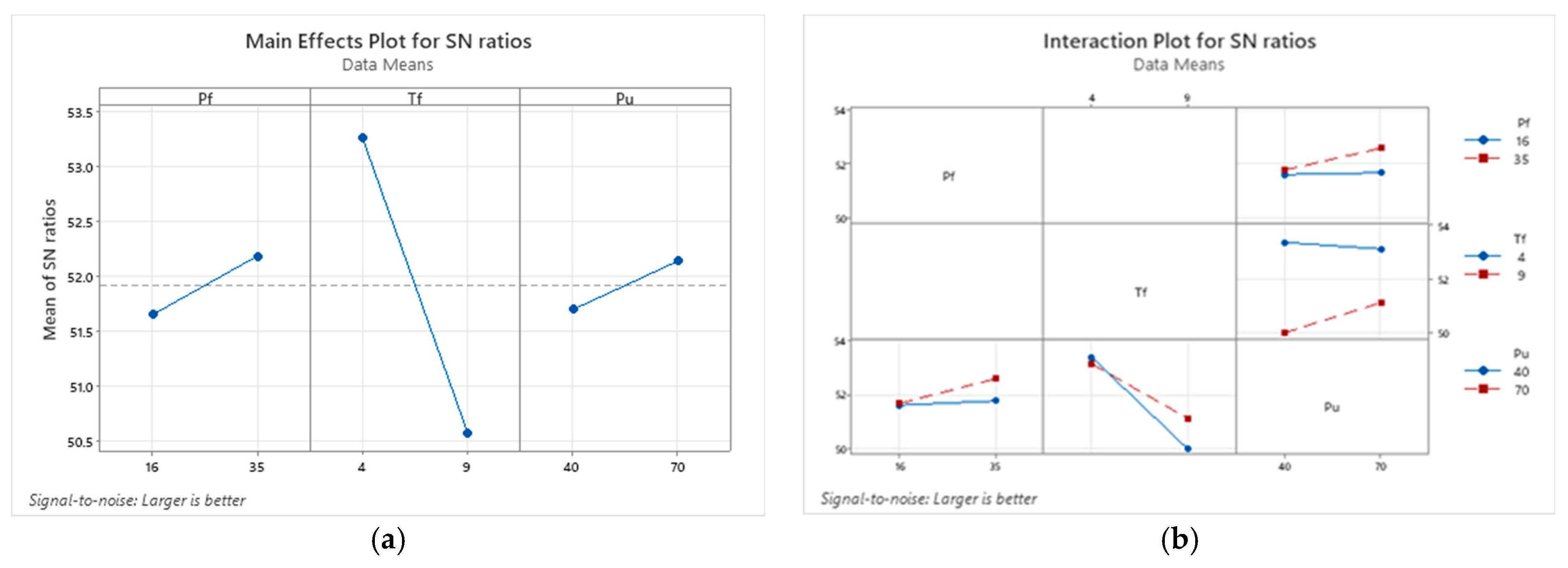
| Low-carbon steel–304 SS | Pf, Tf, Pu | Not significant (optimal factors ignore the interaction) | Pf = 35 bar Tf = 4 s Pu = 70 bar (based on Figure 10a) | 476.56 | 53.59 |
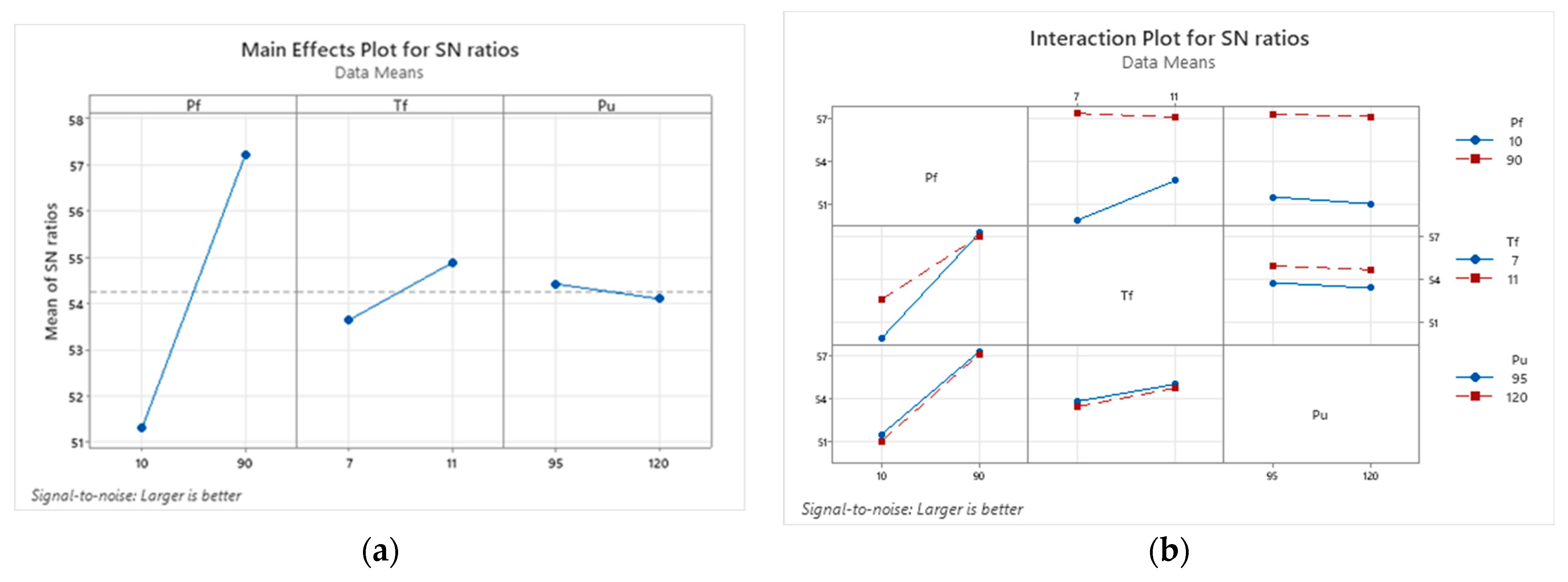
| Medium-carbon steel–304 SS | Pf, Tf, Pu | Significant | Pf = 90 bar Tf = 7 s Pu = 95 bar (based on Figure 11a) | 739.39 | 57.44 |
Disclaimer/Publisher’s Note: The statements, opinions and data contained in all publications are solely those of the individual author(s) and contributor(s) and not of MDPI and/or the editor(s). MDPI and/or the editor(s) disclaim responsibility for any injury to people or property resulting from any ideas, methods, instructions or products referred to in the content. |
© 2022 by the authors. Licensee MDPI, Basel, Switzerland. This article is an open access article distributed under the terms and conditions of the Creative Commons Attribution (CC BY) license (https://creativecommons.org/licenses/by/4.0/).
Share and Cite
Firmanto, H.; Candra, S.; Hadiyat, M.A.; Triastomo, Y.P.; Wirawan, I. Tensile Strength and Microstructure of Rotary Friction-Welded Carbon Steel and Stainless Steel Joints. J. Manuf. Mater. Process. 2023, 7, 7. https://doi.org/10.3390/jmmp7010007
Firmanto H, Candra S, Hadiyat MA, Triastomo YP, Wirawan I. Tensile Strength and Microstructure of Rotary Friction-Welded Carbon Steel and Stainless Steel Joints. Journal of Manufacturing and Materials Processing. 2023; 7(1):7. https://doi.org/10.3390/jmmp7010007
Chicago/Turabian StyleFirmanto, Hudiyo, Susila Candra, Mochammad Arbi Hadiyat, Yesa Priscilla Triastomo, and Ivan Wirawan. 2023. "Tensile Strength and Microstructure of Rotary Friction-Welded Carbon Steel and Stainless Steel Joints" Journal of Manufacturing and Materials Processing 7, no. 1: 7. https://doi.org/10.3390/jmmp7010007
APA StyleFirmanto, H., Candra, S., Hadiyat, M. A., Triastomo, Y. P., & Wirawan, I. (2023). Tensile Strength and Microstructure of Rotary Friction-Welded Carbon Steel and Stainless Steel Joints. Journal of Manufacturing and Materials Processing, 7(1), 7. https://doi.org/10.3390/jmmp7010007