Article

Localized Defects in Cold Die-Compacted Metal Powders

1
Department of Mechanical Engineering, San Diego State University, 5500 Campanile Dr., San Diego, CA 92182, USA
2
Department of Industrial Engineering, University of Trento, Via Sommarive 9, Povo, 38123 Trento, Italy
*
Author to whom correspondence should be addressed.
J. Manuf. Mater. Process. 2022, 6(6), 155; https://doi.org/10.3390/jmmp6060155
Submission received: 17 November 2022 / Revised: 1 December 2022 / Accepted: 3 December 2022 / Published: 6 December 2022
(This article belongs to the Topic Advanced Processes in Metallurgical Technologies)

Abstract

:
In powder metallurgy (PM), the compaction step is fundamental to determining the final properties of the sintered components. The deformation and defectiveness introduced in the powder material during uniaxial die compaction can be correlated to the activation and enhancement of the dislocation pipe diffusion, a lattice diffusion mechanism during the sintering process. Its coefficient depends on the dislocation density. The powder particles are mostly deformed along the direction of the compaction (longitudinal direction) rather than along the compaction plane; consequently, the contact areas perpendicular to the direction of the compaction present a higher density of dislocations and lattice defects. This high density intensifies the shrinkage along the direction of compaction. To demonstrate the influence of uniaxial cold compaction on the material’s stress state the powder particles and their contacts were modeled using spheres made of pure copper. These spheres are compacted in a die at different pressures to better analyze the system’s response at the grade of deformation and the consequent influence on the material’s behavior during the sintering. In the different zones of the sphere, the micro-hardness was measured and correlated to the concentration of dislocations using the model for indentation size effect (ISE). After the compaction, the spheres were more deformed along the longitudinal than the transversal direction. The results obtained using hardness indentation show differences in the dislocation density between the undeformed and deformed spheres and, in the case of the compacted sphere, between the contact area along the longitudinal and the transversal direction.

1. Introduction

In powder metallurgy (PM), different shaping techniques are used, ranging from die-compaction (cold and hot) to pressureless processes, such as slip casing and sinter-assisted additive manufacturing technology, such as binder jetting and powder bed fusion. Uniaxial die-cold compaction and the subsequent sintering is the main process in PM to have components’ mass production [1]. As the properties of sintered parts (e.g., density, dimensions) depend strongly on powder behavior during compaction, the research on powder compaction has seen a wide range of investigation for either pure or mixed powders [2,3,4,5,6,7,8,9,10,11,12,13,14,15]. The change from powder to compact, when exposed to pressure during cold die-compaction, is due to the action of several mechanisms [16,17,18,19]. These, namely the particle rearrangement (by rotations and translations), elastic and plastic deformations developed through the particle contacts, and in addition to that, associated with the strain hardening of the metal, are related to a certain value range of applied pressure.
During the subsequent sintering stage, the metallic bonding between the particles is promoted to obtain the bulk parts. The phenomenon involved is the mass transport towards the inter-particle contact region, which promotes the necks’ formation and growth. During solid-state sintering, different mass transport mechanisms, such as grain boundary, surface, and lattice diffusion, are responsible for neck growth and powder densification. Surface diffusion is the main mechanism involved in neck growth and the consequent strengthening of the material [20,21].
When the bulk of the particles represent the source of the atoms, which flow towards the neck region, as in the case of grain boundary and lattice diffusion, the sintering will lead to shrinkage and consequently to dimensional changes of the components [21]. Grain boundary diffusion is generally considered to be the principal mass transfer involved in solid-state sintering, which promotes densification; meanwhile, lattice diffusion is typically relegated to a marginal role.
Shrinkage kinetics laws are proposed for each mass transport mechanism based on the assumption that at the beginning of the sintering process, the powder’s particles are rigid spheres in a point contact [22,23,24,25,26,27,28,29,30,31,32,33]. Therefore, the effect of the initial cold compaction is neglected.
In reality, during the initial stage of cold compaction, large plastic deformation is introduced in the powder’s particles of the green compact. The dislocations that derive from this huge amount of strains influence the volume diffusion, which results from having great importance during the early stages of sintering. This enhancement of bulk diffusivity is achieved through the dislocation pipe diffusion mechanism [34,35] in which dislocations act as fast paths for the diffusing atoms due to the presence of the disordered core region, which lowers the activation energy for diffusion [36,37]. According to the literature, the resulting diffusivity is proportional to the dislocation density [38,39], and different works were used to estimate the sintering kinetic and to explain the anisotropic shrinkage [40,41].
After the uniaxial die-compaction, a localized high dislocation density is introduced at the contact area within the particles. Since the powder particles show more significant deformation along the compaction direction than in the compaction plane [42,43,44] the dislocation density introduced will be greater for the contacts perpendicular to the compaction direction than for those parallel to it, resulting in an anisotropic dimensional change [42].
In the present work, to model the system of spherical particles described in the classical theory of sintering and to demonstrate the effect of uniaxial cold compaction on the stress state of the material, the powder particles and their contacts were modeled using millimetric spheres made in pure copper. The reason for employing such “large” spheres is to overcome the limitation represented by the challenge of observing the inhomogeneous deformation in the microstructure of micrometric powder particles.
These spheres are compacted in a die subjected to different pressures to better analyze the system’s response based on the grade of deformation and, with the instruction of high dislocation density, which will influence the behavior of the material during the sintering. The dislocation densities are experimentally observed and measured through different experimental methods for undeformed and deformed spheres at different pressure in the die-compaction. First, a specific etching was used to highlight the presence of dislocations on the spheres’ contact areas and undeformed surfaces. Second, using a transmission electron microscope (TEM), observations were conducted to observe the presence of dislocation density in different areas of deformed and undeformed spheres in the material lattice. The third method is based on the correlation between the dislocation density and hardness measurements via micro-indentation [45,46,47]. The qualitative and quantitative results obtained with the different methods are compared and discussed.

2. Materials and Methods

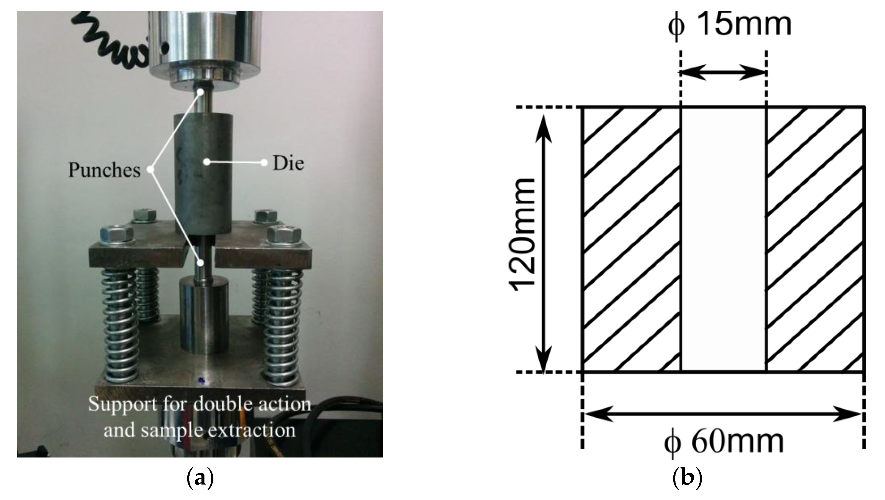
2.1. Experimental Set-Up

The present work used pure copper (99.99% Cu) spheres with diameters in the range of 2.5–3 mm to simulate the mono-sized-powder particles. The size distribution’s influence on compaction is negligible when the distribution is small, as experimental and modeling results have shown [48]. They were uniaxially cold compacted in a rigid die insert in an Instron testing machine (Instron 8516, USA) at two different pressures 196 MPa and 500 MPa.
The compaction system (Figure 1) is composed of the support that allows applying the pressure symmetrically on both ends of the powder column, achieving the double-action compaction. This system also allows easy extraction of the compacted pellet, removing the cylindrical support of the bottom punch and using the Instron to push down the top punch. The copper spheres were loaded in the die to form, once compacted, a cylindrical specimen with 15mm in diameter and 20 mm in height.
Once extracted, the compacted pellets were broken, and the deformed spheres were subdivided and collected.

2.2. Samples Preparation for Observation of the Dislocation

The surface of the copper spheres collected after compaction and those not compacted were analyzed using Scanning Electron Microscopy (SEM, FEI Quanta 450, USA). The surface was polished by immersion in a solution composed of glacial acetic acid (6.5 mL), phosphoric acid 85% (2.7 mL), and nitric acid 65% (0.6 mL) at 60 °C for 1 min. Afterward, an etching solution consisting of equal parts of concentrated HCl, FeCl3•6H2O (10−3 mol cm−3), and HBr (0.5 × 10⁻³ mol cm−3) [49,50,51] was used to highlight the dislocation pits. Etching caused the formation of a large number of pits that may give a semiquantitative indication of the different deformation and dislocations densities in the observed regions. Due to compaction in the contact areas within the particles, plastic deformation and, consequently, increasing defectiveness are introduced in the material’s structure among which there are the dislocations. Therefore, it is expected that the etching will produce a greater quantity of pits since there the density of dislocations will be greater
After etching, the different surface areas were observed with Scanning Electron Microscopy (SEM, FEI Quanta 450, USA), which allowed determining the number of pits by analyzing the obtained images with an image analysis software (ImageJ®). However, it is necessary to consider that even if dislocation density is indeed proportional to the number of pits, it does not exist a one-to-one correspondence between pits and dislocations.
Dislocation etch pit (DEP) technique can be used as semiquantitative measure of the dislocation density using the equation:
ρ d = n A
where n is the number of pits and A [m] is the area of the region.
The presence of dislocations was also observed directly using Transmitting Electron Microscopy (TEM, Philips CM12 electron microscope) analysis. The TEM samples were obtained by sectioning the spheres in correspondence to the center and thinning them down to ~100 µm using sand papers, diamond suspension polishing, and ion milling. The images were taken in the spheres’ bulk and on the surface to analyze the different material structures introduced by the cold compaction.

2.3. Indentation Size Effect (ISE)

The specimens’ preparation is fundamental in obtaining quality experimental data to be analyzed using the indentation size effect (ISE) model developed by Nix and Gao [45]. The issues in the surface preparation can be divided into three groups: (i) surface contamination: oxides, thin organic and contaminants layer; (ii) mechanical damage from surface preparation; (iii) surface roughness.
When contaminants are present on the surface, variation in hardness value with the depth can be measured, caused by a layer with a different hardness from the bulk of specimens and not for an intrinsic characteristic of the material. The mechanical damage from the surface preparation is an extremely important factor that influences the hardness measurements. Obtaining a good surface finish is not sufficient to obtain a surface that is free from mechanical damage and the consequent increase in hardness at small depths due to the deformed layer at the surface. Related to this point, some works show how the surface preparation and the relative hardness measurements can influence the indentation size effect results. In different works, the ISE is studied by analyzing iron and Cu single-crystal [52,53] where different surface preparations were used. These results confirm how the different quality in surface preparation has a fundamental importance in the nanoindentation technique and, consequently, in the ISE analysis.
Lastly, the surface roughness influences the accuracy and introduces a significant error in hardness measurements when its dimension is comparable to the indentation depth [53,54].
Microhardness measurements were conducted on metallographic samples. The metallographic samples were prepared by incorporating the spheres in an epoxy resin, abrading them with sandpapers down to the equatorial cross-section, and initially polished using diamond suspension. The abraded surface was then immersed in the same solution used to clean the sphere surface (glacial acetic acid (6.5 mL), phosphoric acid 85% (2.7 mL), and nitric acid 65% (0.6 mL)) to remove the deformed layers. The Vickers microhardness was measured on these metallographic sections, in the middle of the spheres’ cross-sectional section and at the interparticle contact regions, using three loads: 0.2N, 0.1N, and 0.05N.

3. Results

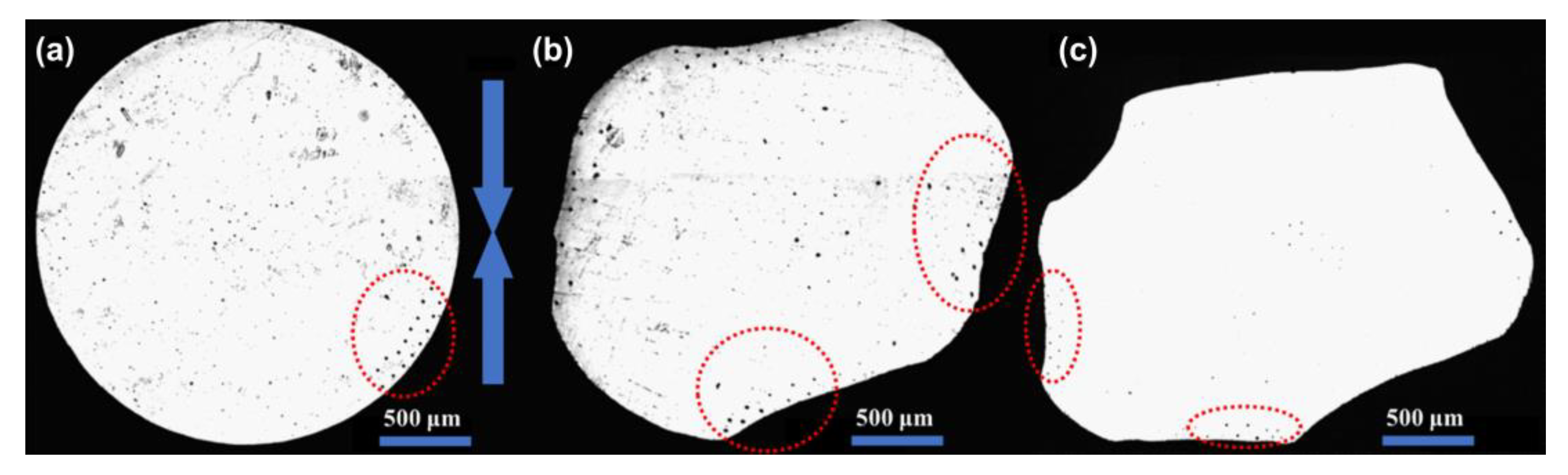
3.1. Die Cold-Compaction
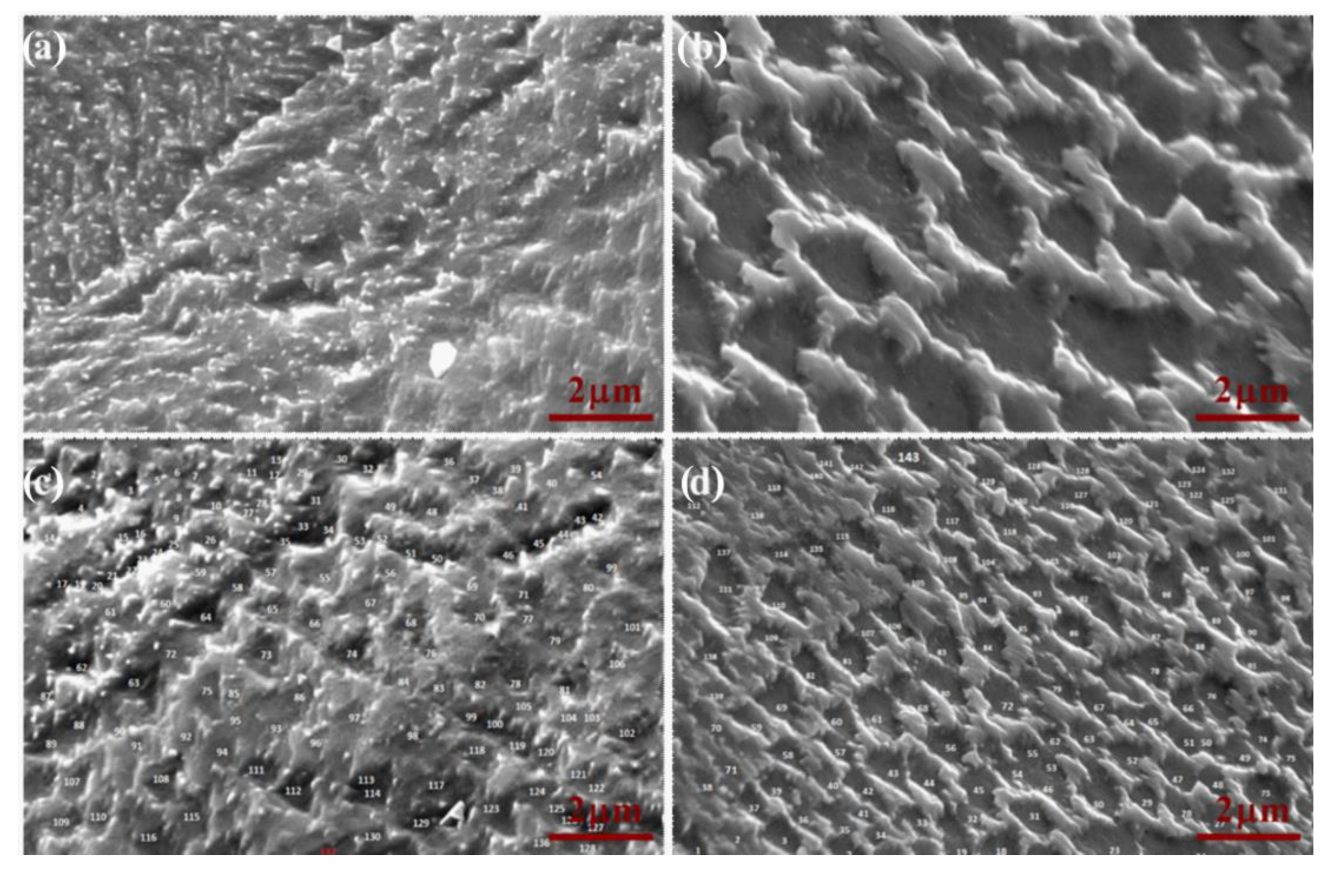
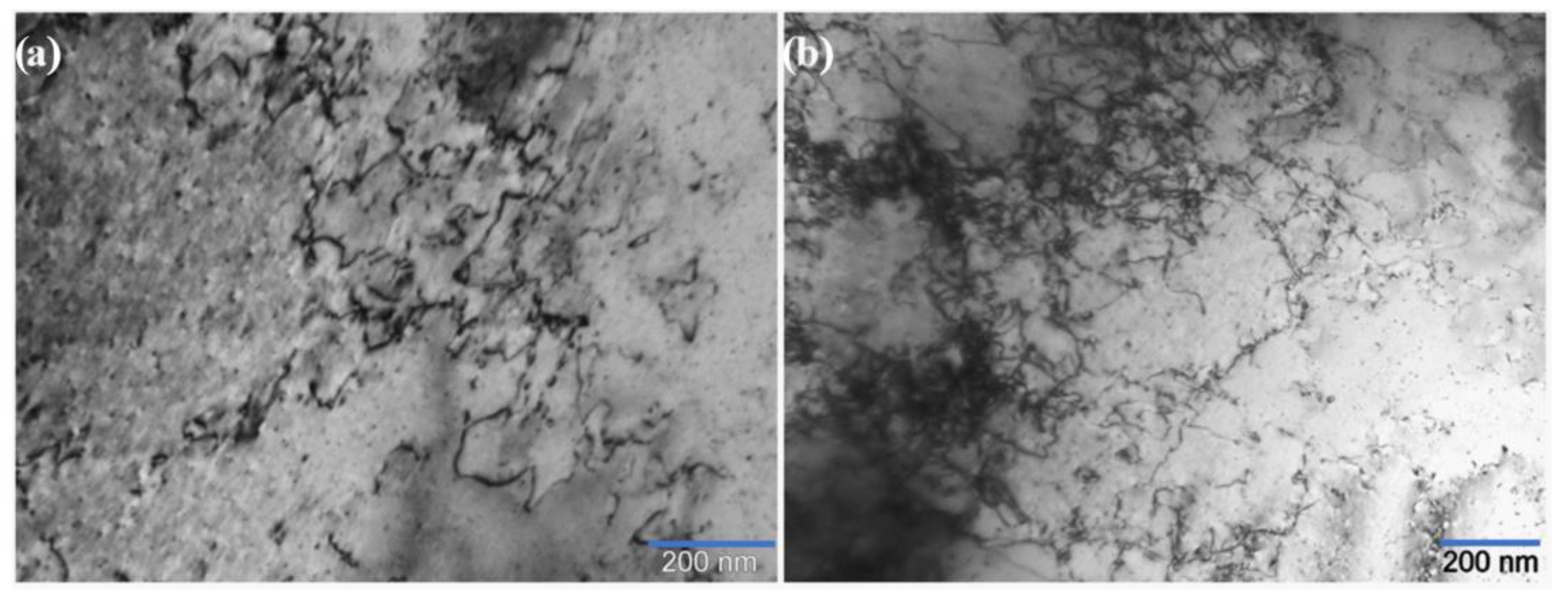
Figure 2 shows the cross-section of the spheres before the cold compaction (a) and after the compaction at 196 MPa (b) and 500 MPa (c).
The compacted spheres clearly show a more extensive deformation in the direction of the compaction with either flat or concave profiles in the contact regions. The difference between the profiles in the contact regions along the compaction direction (blue arrows) and the transversal indicates the difference in the deformation state. In the present work, the measurements were carried out in the contact areas aligned along the compaction (blue arrows) and transversal (plane perpendicular to the compaction direction) directions, and avoiding as much as possible the ambiguously oriented, in order to observe the state of deformation in these two distinct regions. This difference becomes more pronounced on increasing the compaction pressure. Indeed, the contact zones appear larger and more extensively deformed in the longitudinal direction than in the transversal. This different morphology is more evident in the sphere compacted at 500 MPa than at 196 MPa.
In these images, it is possible to notice some highlighted locations (red dotted circles) where the micro-indentation measurements were performed on the surface of the undeformed spheres and the different contact areas for the sphere subjected to the cold compaction.
The effect of plastic deformation introduced into the material with the cold compaction can be observed in Figure 3 where the TEM image of a contact region of a deformed sphere (Figure 3b) is compared with the surface of an undeformed sphere (Figure 3a).
Plastic deformation causes the generation and accumulation of dislocations; they appear roughly uniformly distributed with a slight tendency to form a cell structure, as typical of pure metals during dynamic recovery, which occurs during deformation [55].

3.2. SEM Images

The surface of the spheres after chemical polishing and etching are shown in Figure 4, where the SEM images present the etched contact zones of the sphere compacted at 196.5 MPa. As is possible to notice, the etching produced the formation of a large number of pits. The presence of these pits may give a semiquantitative evaluation of the different deformation and dislocation densities present in the observed regions.
Looking at Figure 4 it is possible to recognize the different morphology obtained for the contact areas present in the transversal plane (Figure 4a,c) and those oriented parallel to the compaction direction (Figure 4b,d). The contact areas, perpendicular to the compaction, show a higher density of the pits, which appear almost overlapped. Meanwhile, for the contact area oriented parallel to the compaction, the pits look more distinct and easier to recognize within each other. Equation 1, through the data obtained from the image analysis of different SEM micrographs, provided a semiquantitative indication of the dislocation density results in 9.8 ± 3.5 × 10¹¹ m−2 in the compaction direction and 4.9 ± 3.2 × 10¹¹ m−2 in the transversal.

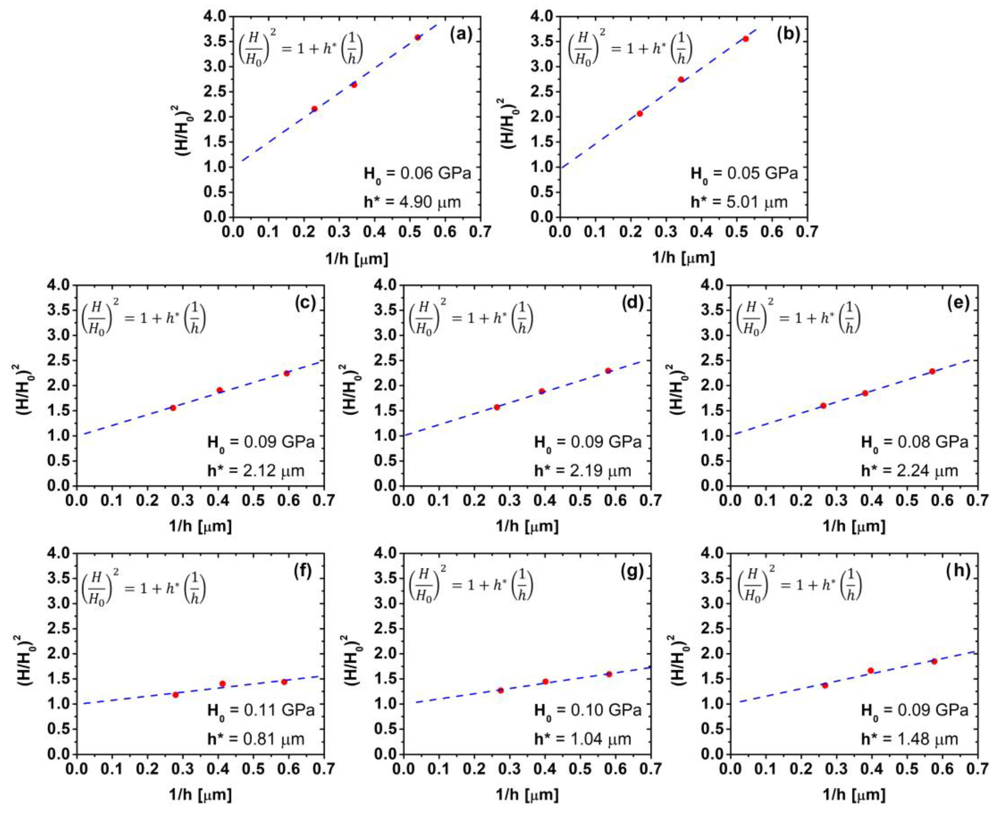
3.3. Indentation Size Effect

ISE method is based on Taylor’s non-local theory of plasticity [56], which indicates, for indentation tests at the micro- and nano-scales, a strong correlation between the depth of the indent and the measured hardness values for depths less than 1 μm. In crystalline materials, this correlation is influenced by the material length scale, a characteristic material parameter that depends on the deformation state of the sample under examination [57,58].
The micro-indentation hardness H and the corresponding indentation depts h [μm] are used as input for linear relationship derived from the main ISE equation:
H 2 = H 0 2 1 + h * h
where H0 is the hardness that arises from the pre-existing dislocations (ρso); therefore, it does not derive from the indentation process itself. The characteristic depth of the material h* [μm] depends on the properties of indented materials and the angle of contact between the indenter tip and the sample surface θ (22.0 deg for Vickers tips, utilized in the present case):
h * = 3 tan 2 θ 2 b ρ s    
where b [m] is the Burgers vector of the dislocation. Subsequent work [57,58] introduced a corrective factor ( r ¯ ) for the size of the plastic zone, and Equation (3) can be modified to determine the dislocation density as:
ρ s = 3 r ¯   tan 2 θ 2 b h *  
where the Nye factor r ¯ , in case of materials characterized by FCC crystal structure, assumes approximately the value of 1.9 [59].
The plot of the measurements following the depth dependence of the hardness described by Equation (2) provides information on the value of H0, which is the intercept, and the slope, which is h*[μm]. The data can be displayed as a plot of (H/H0)2 vs. 1/h as shown in Figure 5.
An excellent agreement with the prediction of the model can be observed. The characteristic depth values obtained can be used in Equation (4), which provides the estimation of the dislocation density present in the different areas for all the studied cases. The obtained h*[μm] and correspondent dislocation density ρs [m−2] calculated with Equation (4) are reported in Table 1.
For the undeformed spheres, the dislocation densities calculated through the hardness measurements on the surface and in the core are 2.84 × 10¹³ m−2 and 2.78 × 10¹³ m−2, respectively. The slight difference between these values which are in accordance with the literature [60,61].
In the deformed spheres at 196 MPa, an increase in the dislocation density has been measured in all the different analyzed areas. The dislocation density is increased by less than one order of magnitude after compaction. The percentage increase (C) in the dislocation density is given by:
C = ρ s d e f ρ s u n d e f ρ s u n d e f · 100
The dislocation density is slightly higher in the perpendicular contact zone than in the parallel.
For the compaction at 500 MPa, the increase in dislocation density is even more noticeable with the core, which reached a value just below an order of magnitude higher than the undeformed case. For the contact areas, the largest density has been calculated in the perpendicular contact with 1.72 × 10¹⁴ m−2; for the parallel contacts, the measured dislocation density was 1.34 × 10¹⁴ m−2, which corresponds to an increment in the dislocation density value of 506% and 372%, respectively.

4. Discussion

The study of the plastic deformation and in particular of the structural defectiveness in the metallic powders after die cold compaction is quite a hard challenge since deformation is highly localized in the interparticle contact regions where a large density of dislocations is accumulated. Experimental methods based on X-ray provide a result that is averaged in the investigated volume; therefore, they are not suitable to highlight the structural defectiveness close to the neck regions in the green body, where the diffusion mechanisms responsible for sintering occur and are greatly affected by dislocations. Contrarily EBSD is a powerful method to investigate localized deformation phenomena, as shown by Wendel et al. [62], but it is only sensitive to geometrically necessary dislocations, providing a partial representation of the local structural defectiveness. A quantitative analysis of dislocation density can be carried out using TEM that is rather time consuming and expensive if a statistically sound result is needed.
The two methods used in the present work could be in principle promising, and they have been experimented using millimetric particles in place of micrometric powders to facilitate the analysis of the materials in the contact zones and to mimic the spherical powder particles used in the classical sintering models.
The spheres were compacted in a cylindrical die and subjected to two uniaxial cold compaction with two pressures, 196 MPa and 500 MPa. The undeformed spheres and the spheres subjected to the two different compaction loads were analyzed through different methods to compare the effect of the compaction in different directions.
The surface of the spheres was first chemically polished and etched. Through the SEM observations and image analysis, an initial estimation of the dislocation density has been obtained from the density of pits created by etching. This method provided initial confirmation of a higher density of structural defectiveness in the contact areas perpendicular to the compaction’s direction. The dislocation density obtained using this method is underestimated since there is not a one-to-one correlation between the etching pits and dislocations.
The second experimental method used in the present work to study the localized deformation inducted by the uniaxial die cold compaction is based on the indentation size effect proposed by Nix and Gao. Micro-indentations measurements were conducted on the central cross-section of the spheres in correspondence with the contact area and in the core. The results reported in Table 1 can be compared with literature data. Table 2 reports dislocation density measured by some authors in pure copper in different conditions: annealed, cold worked, ECAPed. The experimental method is XRD in all the case, with the exception of Refiee et al. [63] who used Electrochemical Impedance Spectroscopy. In all the cases the results are significant of the defectiveness of the material, which is homogeneous after annealing, cold working and ECAP.
The dislocation density of the as received copper spheres (annealed) as well as of the deformed spheres are comparable to data reported in Table 2. In particular, the dislocation density in the interparticle regions is of the same order of magnitude of data reported for cold worked copper with an intermediate amount of strain, while it is smaller than that introduced by ECAP. This is a reasonable result that suggests to use the indentation size effect to estimate dislocation density in cold compacted micrometric powders using nanoindentation, due to the much smaller extension of the deformed region in comparison to that obtained on the millimetric powders here investigated.

5. Conclusions

The influence of uniaxial cold compaction on deformation and the structural defectiveness of copper spheres with 2.5–3 mm diameter was investigated. After uniaxial cold compaction in a rigid die the spheres are more deformed in the transversal than in the parallel contact areas. Plastic deformation occurs by dislocation gliding, as shown by TEM analyses, which reveal a large density of dislocations in the contact regions. A specific etching was used to highlight the dislocations in the rich areas in the contact regions and on the surface of the undeformed spheres. Using SEM images, semiquantitative information about a higher dislocation density in the contact areas perpendicular to the compaction direction than in those parallel to it was obtained through the image analysis software ImageJ®. A quantitative analysis of the structural defectiveness of spheres compacted with different pressures was carried out using microhardness and the indentation size effect model. Dislocation density increases after compaction at both pressures, and it is higher in the contact areas perpendicular to the compaction direction than in those parallel to it. The difference increases with the compaction pressure. In particular, compaction at 500 MPa, which results in significant deformation of the copper spheres, increases dislocation density by 500% and by 370% in the two directions, respectively. The dislocation density in the interparticle regions is of the same order of magnitude of data reported in the literature for cold worked copper with an intermediate amount of strain

Author Contributions

Conceptualization, A.M. and E.T.; methodology, A.M., E.T. and G.I.; software, E.T.; validation, E.T.; investigation, E.T. and G.I.; data curation, E.T.; writing—original draft preparation, E.T.; writing—review and editing, A.M. and E.T.; supervision, A.M. All authors have read and agreed to the published version of the manuscript.

Funding

This research was funded by Minority Serving Institutions Science, Technology, Engineering and Mathematics Research and Development Consortium (MSRDC) (Award No: D01-W911-SR-14-2-0023), US Army DEVCOM—Army Research Laboratory (Contract W911-NF-20-2-0226), and National Science Foundation (Award 2119832).

Conflicts of Interest

The authors declare no conflict of interest. The funders had no role in the design of the study; in the collection, analyses, or interpretation of data; in the writing of the manuscript; or in the decision to publish the results.

References

  1. Kruzhanov, V.S. Modern Manufacturing of Powder-Metallurgical Products with High Density and Performance by Press–Sinter Technology. Powder Metall. Met. Ceram. 2018, 57, 431–446. [Google Scholar] [CrossRef]
  2. Gurson, A.L. Continuum theory of ductile rupture by void nucleation and growth—Part 1: Yield criteria and flow rules for porous ductile media. J. Eng. Mater. Technol. 1977, 99, 2–15. [Google Scholar] [CrossRef]
  3. Arzt, E. The influence of an increasing particle coordination on the densification of spherical powders. Acta Metall. 1982, 30, 1883–1890. [Google Scholar] [CrossRef] [Green Version]
  4. Fleck, N.A.; Kuhn, L.T.; McMeeking, R.M. Yielding of metal powder bonded by isolated contacts. J. Mech. Phys. Solids 1992, 40, 1139. [Google Scholar] [CrossRef]
  5. Govindarajan, R.M.; Aravas, N. Deformation processing of metal powders: Part I—Cold isostatic pressing. Int. J. Mech. Sci. 1994, 36, 343–357. [Google Scholar] [CrossRef]
  6. Lange, F.F.; Atteraas, L.; Zok, F.; Porter, J.R. Deformation consolidation of metal powders containing steel inclusions. Acta Metall. Mater. 1991, 39, 209–219. [Google Scholar] [CrossRef]
  7. Besson, J.; Evans, A.G. The effect of reinforcements on the densification of a metal powder. Acta Metall. Mater. 1992, 40, 2247–2255. [Google Scholar] [CrossRef]
  8. Gurson, A.; McCabe, T. Experimental determination of yield functions for compaction of blended metal powders. In Proceedings of the MPIF/APMI World Congress on Powder Metallurgy and Particular Materials, San Francisco, CA, USA, 21–26 June 1992. [Google Scholar]
  9. Turner, C.D.; Ashby, M.F. The cold isostatic pressing of composite powders—I: Experimental investigations using model powders. Acta Mater. 1996, 44, 4521–4530. [Google Scholar] [CrossRef]
  10. Bouvard, D. Modelling the densification of powder composites by power law creep. Acta Metall. Mater. 1993, 41, 1413–1420. [Google Scholar] [CrossRef]
  11. Zavaliangos, A.; Wen, J. The effects of mixing quality on the densification of heterogeneous powder mixtures by pressure. In Proceedings of the International Workshop on Modelling of Metal Powder Forming Process, Grenoble, France, 21–23 July 1997. [Google Scholar]
  12. Kim, K.T.; Cho, J.H. A densification model for mixed metal powder under cold compaction. Int. J. Mech. Sci. 2001, 43, 2929–2946. [Google Scholar] [CrossRef]
  13. StorNakers, B.; Fleck, N.A.; McMeeking, R.M. The visco-plastic compaction of composite powders. J. Mech. Phys. Solids 1999, 47, 785–788. [Google Scholar] [CrossRef]
  14. Zago, M.; Molinari, A.; Rambelli, A.; Pederzini, G.; Cristofolini, I. Study of the influence of geometry and particle size on the densification and compaction mechanics of uniaxially cold compacted rings. Int. J. Powder Metall. 2019, 55, 29–38. [Google Scholar]
  15. Cristofolini, I.; Molinari, A.; Zago, M.; Pederzini, G.; Rambelli, A.; Crosa, R.; Della Ricca, F. The influence of lubricant on the constitutive model of low alloy steel powder mix. Advances in Powder Metallurgy and Particulate Materials 2018. In Proceedings of the 2018 International Conference on Powder Metallurgy and Particulate Material, Sant Antonio, TX, USA, 17–20 June 2018. [Google Scholar]
  16. Heckel, R.W. Density-pressure relationship in powder compaction. Trans. Met. Soc. AIME 1961, 221, 671–675. [Google Scholar]
  17. Heckel, R.W. An analysis of powder compaction phenomena. Trans. Metall. Soc. AIME 1961, 221, 1001–1008. [Google Scholar]
  18. Donachie, M.J.; Burr, M.F. Effects of pressing on metal powders. JOM 1963, 15, 849–854. [Google Scholar] [CrossRef]
  19. German, R.M. Powder Metallurgy Science; Metal Powder Industries Federation: Princeton, NJ, USA, 1984. [Google Scholar]
  20. Maximenko, A.L.; Olevsky, E.A. Effective diffusion coefficients in solid-state sintering. Acta Mater. 2004, 52, 2953–2963. [Google Scholar] [CrossRef]
  21. Bordia, R.K.; Kang, S.J.; Olevsky, E.A. Current understanding and future research directions at the onset of the next century of sintering science and technology. J. Am. Ceram. Soc. 2017, 100, 2314–2352. [Google Scholar] [CrossRef] [Green Version]
  22. Swinkels, F.B.; Ashby, M.F. A second report on sintering diagrams. Acta Metall. 1981, 29, 259–281. [Google Scholar] [CrossRef]
  23. Exner, H.E.; Arzt, E.; Sōmiya, S.; Moriyoshi, Y. Sintering Key Papers; Springer: Dordrecht, The Netherlands, 1990; pp. 157–184. [Google Scholar]
  24. Frenkel, J.J. Viscous flow of crystalline bodies under the action of surface tension. J. Phys. 1945, 9, 385. [Google Scholar]
  25. Pines, B.Y. Mechanism of sintering. J. Tech. Phys. 1946, 16, 737. [Google Scholar]
  26. Herring, C. Effect of change of scale on sintering phenomena. J. Appl. Phys. 1950, 21, 301–303. [Google Scholar] [CrossRef]
  27. Kingery, W.D.; Berg, M. Study of the initial stages of sintering by viscous flow, evaporation—Condensation, and self-diffusion. In Sintering Key Papers; Springer: Dordrecht, The Netherlands, 1990; pp. 367–382. [Google Scholar]
  28. Coble, R.L. Sintering crystalline solids. I. Intermediate and final state diffusion models. J. Appl. Phys. 1961, 32, 787–792. [Google Scholar] [CrossRef]
  29. Mackenzie, J.K.; Shuttleworth, R. A phenomenological theory of sintering. Proc. Phys. Soc. B 1949, 62, 833. [Google Scholar] [CrossRef]
  30. Thümmler, F.; Thomma, W. The sintering process. Metall. Rev. 1967, 12, 69–108. [Google Scholar] [CrossRef]
  31. Johnson, D.L. New method of obtaining volume, grain-boundary, and surface diffusion coefficients from sintering data. J. Appl. Phys. 1969, 40, 192–200. [Google Scholar] [CrossRef]
  32. Exner, H.E. Principles of single-phase sintering. Rev. Powder Metall. Phys. Ceram. 1979, 1. [Google Scholar]
  33. Kang, S.J. Sintering: Densification, Grain Growth and Microstructure; Elsevier: Amsterdam, The Netherlands, 2004. [Google Scholar]
  34. Kaysser, W.A.; Hofmann-Amtenbrink, M.; Petzow, G. Activated Sintering. In Sintering’85; Springer: Boston, MA, USA, 1987; pp. 121–132. [Google Scholar]
  35. Ruoff, A.L.; Balluffi, R.W. Strain-enhanced diffusion in metals. II. Dislocation and grain-boundary short-circuiting models. J. Appl. Phys. 1963, 34, 1848–1853. [Google Scholar] [CrossRef]
  36. Huang, J.; Meyer, M.; Pontikis, V. Is pipe diffusion in metals vacancy controlled? a molecular dynamics study of an edge dislocation in copper. Phys. Rev. Lett. 1986, 63, 628–631. [Google Scholar] [CrossRef]
  37. Rabier, J.; Puls, M.P. Atomistic calculations of point-defect interaction and migration energies in the core of an edge dislocation in NaCl. Philos. Mag. A 1989, 59, 533–546. [Google Scholar] [CrossRef]
  38. Cohen, M. Self-diffusion during plastic deformation. Trans. Jpn. Inst. Met. 1970, 11, 145–151. [Google Scholar]
  39. Hart, E.W. On the role of dislocations in bulk diffusion. Acta Metall. 1957, 5, 597. [Google Scholar] [CrossRef]
  40. Torresani, E.; Giuntini, D.; Zhu, C.; Harrington, T.; Vecchio, K.S.; Molinari, A.; Bordia, R.K.; Olevsky, E.A. Anisotropy of mass transfer during sintering of powder materials with pore–particle structure orientation. Metall. Mater. Trans. A 2019, 50, 1033–1049. [Google Scholar] [CrossRef] [Green Version]
  41. Baselli, S.; Torresani, E.; Zago, M.; Amirabdollahian, S.; Cristofolini, I.; Molinari, A. Sintering shrinkage of uniaxial cold compacted iron: Influence of the microstructure on the anisothermal and isothermal shrinkage of uniaxial cold-compacted iron. Powder Metall. 2018, 61, 276–284. [Google Scholar] [CrossRef]
  42. Zago, M.; Cristofolini, I.; Molinari, A. New interpretation for the origin of the anisotropic sintering shrinkage of AISI 316L rings based on the anisotropic stress field occurred on uniaxial cold compaction. Powder Metall. 2019, 62, 115–123. [Google Scholar] [CrossRef]
  43. Hewitt, R.L.; Wallace, W.; de Malherbe, M.C. Plastic deformation in metal powder compaction. Powder Metall. 1974, 17, 1–2. [Google Scholar] [CrossRef]
  44. Cristofolini, I.; Pederzini, G.; Rambelli, A.; Molinari, A. Densification and deformation during uniaxial cold compaction of stainless steel powder with different particle size. Powder Metall. 2016, 59, 73–84. [Google Scholar] [CrossRef]
  45. Nix, W.D.; Gao, H. Indentation size effects in crystalline materials: A law for strain gradient plasticity. J. Mech. Phys. Solids 1998, 46, 411–425. [Google Scholar] [CrossRef]
  46. Swadener, J.G.; George, E.P.; Pharr, G.M. The correlation of the indentation size effect measured with indenters of various shapes. J. Mech. Phys. Solids 2002, 50, 681–694. [Google Scholar] [CrossRef]
  47. Zong, Z.; Lou, J.; Adewoye, O.O.; Elmustafa, A.A.; Hammad, F.; Soboyejo, W.O. Indentation size effects in the nano-and micro-hardness of fcc single crystal metals. Mater. Sci. Eng. A 2006, 434, 178–187. [Google Scholar] [CrossRef]
  48. Olsson, E.; Larsson, P.L. On the effect of particle size distribution in cold powder compaction. J. Appl. Mech. 2012, 79, 051017. [Google Scholar] [CrossRef]
  49. Livingston, J.D. The density and distribution of dislocations in deformed copper crystals. Acta Metall. 1962, 10, 229–239. [Google Scholar] [CrossRef]
  50. Watanabé, J.; Sugawara, S. Some Observations of Dislocation Etch Pits on {111} Surfaces of Cu and Cu–Al Dilute Alloy Crystals. Trans. Jpn. Inst. Met. 1978, 19, 511–518. [Google Scholar] [CrossRef] [Green Version]
  51. Marukawa, K. Dark and Light Pits on (111) Surface of Copper. Jpn. J. Appl. Phys. 1967, 6, 944. [Google Scholar] [CrossRef]
  52. Liu, Y.; Ngan, A.H. Depth dependence of hardness in copper single crystals measured by nanoindentation. Scr. Mater. 2001, 44, 237–241. [Google Scholar] [CrossRef]
  53. Wei, Y.; Wang, X.; Zhao, M. Size effect measurement and characterization in nanoindentation test. J. Mater. Res. 2004, 19, 208–217. [Google Scholar] [CrossRef]
  54. Pathak, S.; Stojakovic, D.; Doherty, R.; Kalidindi, S.R. Importance of surface preparation on the nano-indentation stress-strain curves measured in metals. J. Mater. Res. 2009, 24, 1142–1155. [Google Scholar] [CrossRef]
  55. Bullen, F.P.; Hutchison, M.M. Dynamic recovery from strain-hardening in polycrystalline copper and aluminum. Philos. Mag. 1962, 7, 557–572. [Google Scholar] [CrossRef]
  56. Gao, H.; Huang, Y. Taylor-based nonlocal theory of plasticity. Int. J. Solids Struct. 2001, 38, 2615–2637. [Google Scholar] [CrossRef]
  57. Voyiadjis, G.Z.; Almasri, A.H. Variable material length scale associated with nanoindentation experiments. J. Eng. Mech. 2009, 135, 139–148. [Google Scholar] [CrossRef]
  58. Faghihi, D.; Voyiadjis, G.Z. Determination of nanoindentation size effects and variable material intrinsic length scale for body-centered cubic metals. Mech. Mater. 2012, 44, 189–211. [Google Scholar] [CrossRef]
  59. Schatt, W.; Friedrich, E. Dislocation-activated sintering processes. In Sintering’85; Springer: Boston, MA, USA, 1987; pp. 133–141. [Google Scholar]
  60. Lee, D.J.; Yoon, E.Y.; Ahn, D.H.; Park, B.H.; Park, H.W.; Park, L.J.; Estrin, Y.; Kim, H.S. Dislocation density-based finite element analysis of large strain deformation behavior of copper under high-pressure torsion. Acta Mater. 2014, 76, 281–293. [Google Scholar] [CrossRef]
  61. Hommel, M.; Kraft, O. Deformation behavior of thin copper films on deformable substrates. Acta Mater. 2001, 49, 3935–3947. [Google Scholar] [CrossRef]
  62. Wendel, G.; Manchili, S.K.; Hryha, E.; Nyborg, L.; Wendel, J.; Manchili, S.K.; Hryha, E.; Nyborg, L. Sintering behaviour of compacted water-atomised iron powder: Effect of initial state and processing conditions. Powder Metall. 2020, 63, 338–348. [Google Scholar] [CrossRef]
  63. Rafiee, E.; Farzam, M.; Golozar, M.A.; Ashrafi, A. An investigation on dislocation density in cold-rolled copper using electrochemical impedance spectroscopy. ISRN Corros. 2013, 2013, 921825. [Google Scholar] [CrossRef] [Green Version]
  64. Schafler, E.; Zehetbauer, M.; Ungar, T. Measurement of screw and edge dislocation density by means of X-ray Bragg profile analysis. Mater. Sci. Eng. A 2001, 319, 220–223. [Google Scholar] [CrossRef]
  65. Miyajima, Y.; Okubo, S.; Abe, H.; Okumura, H.; Fujii, T.; Onaka, S.; Kato, M. Dislocation density of pure copper processed by accumulative roll bonding and equal-channel angular pressing. Mater. Charact. 2015, 104, 101–106. [Google Scholar] [CrossRef]
  66. De Sousa, T.G.; Sordi, V.L.; Brandao, P. Dislocation Density and Texture in Copper Deformed by Cold Rolling and Ecap. Mater. Res. 2018, 21, e20170515. [Google Scholar] [CrossRef]
  67. Berecz, T. Dislocation densities in cold worked copper by electron and X-ray diffraction methods. Mater. Sci. Technol. 2019, 35, 513–519. [Google Scholar] [CrossRef]
Figure 1. (a) Compaction system involved in the present work, and (b) die dimensions.
Jmmp 06 00155 g001
Figure 2. Barycentric section of (a) sphere before the cold-compaction. (b) deformed sphere at 196 MPa and (c) at 500 MPa; the arrows indicate the direction of the compaction. In the red dotted circles, the micro-indentation imprints are shown.
Jmmp 06 00155 g002
Figure 3. TEM images obtained (a) on the surface of undeformed spheres, (b) in the contact region.
Jmmp 06 00155 g003
Figure 4. SEM images of the sphere compacted at 196.5 MPa: (a) etching pits in contact zone along the direction of compaction and (b) in the transversal plane at 10,000×; (c) Count of pits for the direction parallel to the pressure at 10,000× and (d) transversal at 5000×.
Jmmp 06 00155 g004
Figure 5. Data of micro-indentation measurements for the undeformed spheres at the (a) surface and (b) core; compacted spheres at 196 MPa at the (c) perpendicular contacts, (d) parallel contacts and (e) core; compacted spheres at 500 MPa at the (f) perpendicular contacts, (g) parallel contacts and (h) core.
Jmmp 06 00155 g005
Table 1. Results obtained using Nix and Gao model with the micro-indentation measurements.
Undeformed196 MPa2500 MPa
SurfaceCorePerpend.ParallelCorePerpend.ParallelCore
h* [μm]4.905.012.122.192.240.811.041.48
ρs [1013∙1/m2]2.842.786.586.376.2317.213.49.4
C132%124%124%506%372%238%
Table 2. Literature data for the dislocation density present in copper for different strain conditions.
First AuthorConditionDislocation Density [m−2]
Refiee [63]Annealed5.3 × 1014
Cold rolled, 10 to 50 reduction in area9.9 × 1014 to 1.72 × 10¹⁵
Schafler [64]Cold worked, 0.064 to 0.33 T0.96 to 1.86 × 10¹⁵
Miyajima [65]Accumulative cold rolled7 × 1015
De Souza [66]Annealed1 × 1012
Cold worked, 10 to 85% reduction in area1 × 1014 to 1 × 10¹⁶
ECAP 1 to 4 passes, 0.7 to 2.7 equivalent strain5 × 1016 to 1 × 10¹⁷
Berecz [67]Cold drawn4.9 × 1014
ECAP9 × 1014
Publisher’s Note: MDPI stays neutral with regard to jurisdictional claims in published maps and institutional affiliations.

