Article

Heat Dissipation Plays Critical Role for Longevity of Polymer-Based 3D-Printed Inserts for Plastics Injection Moulding †

PRISM Research Institute, Technological University of the Shannon, Dublin Rd, N37 HD68 Athlone, Ireland
*
Author to whom correspondence should be addressed.
This paper is an extended version of conference paper by M. Hopkins, S. Gunbay, C. Hayes, V.F. Moritz, E. Fuenmayor, J.G. Lyons, D.M. Devine “Stereolithography (SLA) utilised to print injection mould tooling in order to evaluate thermal and mechanical properties of commercial polypropylene”. Procedia Manuf. 2021, 55, 205–212. 10.1016/j.promfg.2021.10.029.
J. Manuf. Mater. Process. 2022, 6(5), 117; https://doi.org/10.3390/jmmp6050117
Submission received: 28 July 2022 / Revised: 29 September 2022 / Accepted: 29 September 2022 / Published: 8 October 2022

Abstract

:
Injection moulding is a polymer processing method of choice for making plastic parts on industrial scale, but its traditional mould is made from tooling steel with time-consuming and costly production. Additive manufacturing technologies arise as an alternative for creating mould inserts at lower costs and shorter lead times. In this context, this study describes a series of stereolithography (SLA)-printed injection mould inserts fabricated from two photopolymer resins, utilised to mould standard tensile specimens of a commercial-grade polypropylene, aiming to evaluate effects on the polymer’s thermal and mechanical properties. Our results demonstrated that the glass fibre-filled resin inserts withstood more moulding cycles before failure, had superior mechanical properties, higher Tg and greater thermal conductivity. Calorimetric data revealed that PP thermal properties and degree of crystallinity were little affected, while mechanical testing suggests a significant effect in the elongation at break. Thus, these findings highlight the importance of adequate heat extraction during injection moulding and endorse further application of SLA mould inserts for the manufacturing of injection-moulded plastic parts in the case of prototypes or small batches, provided suitable cooling is made available, contributing to the feasibility and affordability of employing this approach for an industrial setting.

1. Introduction

Injection moulding (IM) is a polymer processing technique that consists in the injection of molten materials to be shaped under high-pressure conditions into a mould cavity. In the plastics industry, IM plays a major role as a processing technique since at least 30% of all the plastic parts are manufactured through this process [1]. Due to its high economy of scale and ease of manufacture applying to a variety of resins, IM is the method of choice for making 3-dimensional plastic parts on an industrial scale. Nevertheless, high-quality moulds are made from hardened tooling steel, and their production is not only time-consuming but also costly [2,3]. As an alternative of advanced method for creating mould inserts, additive manufacturing (AM) technologies allow the production of functional mould prototypes as it can fabricate high-complexity three-dimensional (3D) parts by building them layer-by-layer [4]. One of the most common methods of AM is the pioneering Stereolithography (SLA), which relies on UV curing of photopolymerisable resins [5].
Designing moulds using AM has several benefits, such as (i) high speed and low-cost production, (ii) reduced use of material, (iii) versatility in design, and (iv) allowing complex geometry and intricate surface details [6]. SLA has been investigated as a potential technology for hybrid moulds [7,8,9,10]. Westphal et al. found that polymers with solubility parameters similar to that of the SLA resin may cause wear due to chemical adhesion, as well as special attention should be paid regarding the ejection system design when moulding high-shrinkage materials [8]. Nevertheless, polymer moulds additively manufactured have demonstrated susceptibility to geometric inaccuracies, mould temperature control, tolerance and repeatability [11,12]. Attempting to overcome these challenges, researchers have incorporated new technologies into the process aiming to improve structural health monitoring (SHM) of moulds and composites [13]. Since structural integrity plays a crucial role in plastic components, glass fibre reinforced composites have been reported to improve not only the strength but also the thermomechanical behaviour of a polymeric matrix [14].
One of the utmost used polymer materials in the production of plastic parts is the commercial isotactic polypropylene (PP) due to its excellent thermal and mechanical properties, low cost and great versatility [2], but if the moulding conditions (especially mould temperature) for PP are not correct and consistent, the properties of the moulded parts will be affected. Moreover, knowledge of pressure, temperature and melt state distributions of the polymers is required to ensure part quality in injection moulding [15]. In general, conventional moulds manufactured from hardened steel can dissipate the thermal energy from the polymer melt allowing it to crystallise in a controlled manner. On the other hand, polymer-based AM mould inserts are thermal insulators; hence, preventing controlled crystallisation of the moulded material, which leads to misshaped parts with unstable morphology, imperfections and, more importantly, with reduced mechanical properties [16,17]. Studies have already aimed at cavity temperature changes with moulding cycle as well as at the impact of the 3D-printed insert on the cycle time [7,12,18,19], but the investigation of the specific effects of the IM insert material on the moulded parts’ properties has not been extensively explored.
Thus, this study describes a series of SLA-printed injection mould inserts utilised to mould standard tensile specimens, aiming to evaluate the thermal and mechanical properties of a commercial-grade polypropylene with particular attention to their differences due to being shaped in mould inserts made of different materials.

2. Materials and Methods

2.1. Materials

Commercial-grade Sasol PP HRN 100 polypropylene, described as a general-purpose injection moulding material for situations in which rigidity and shorter cycle times are required, was utilised in this study as the trial material [20]. The AM mould inserts were fabricated from commercially available photopolymer resins, namely FormLabs HighTemp, which is a heat-resistant material for precision applications [21], and FormLabs Rigid 10k, a glass-fibre high-performance resin [22]. Some of the mechanical properties of these resins are displayed in Table 1.

2.2. Fabrication of Mould Inserts

Identical mould inserts were designed with SolidWorks 2020 (Dassault Systems SolidWorks Corp., Waltham, MA, USA). The inserts designed consist of runners, gates and two cavities of ASTM D638 type V tensile specimen (Figure 1a). Mould inserts were fabricated in a FormLabs 2 (FormLabs Ltd., Somerville, MA, USA) SLA three-dimensional printer utilising a 250 mW laser at 405 nm wavelength, with a layer thickness of 50 µm in a 45° orientation with respect to the top plan, using FormLabs HighTemp and FormLabs Rigid 10k photopolymer resins. Following, the 3D-printed parts were post-cured in a UV chamber for 40 min. Four mould inserts were fabricated from each photopolymer resin. A tooling-steel mould with the same design was employed as industry standard control.

2.3. Injection Moulding

A Babyplast 6/10P injection moulding machine was utilised in this study. A temperature profile of 240 (plastification), 230 (chamber) and 220 °C (nozzle) was used, with cooling time of 18 s, first and second injection pressures of 85 and 75 bar respectively, and clamp pressure of 50 bar, ensuring a fully filled cavity. Babyplast injection moulding machine has a two-stage filling step to fully fill the mould cavity. First, it delivers most of the molten material, then the piston moves backward and the injection chamber recharges, and finally the piston moves forward again, delivering the rest of the material at the second injection pressure, and from that point on the packing stage starts. The hydraulic pressure for the ejection system was 60 bar, and the ejection speed was 60 mm·s−1, with two strokes. These processing parameters were employed for the steel mould as well as both the 3D-printed inserts.
First, PP specimens were moulded using the with the standard steel mould. Subsequently, a steel bolster, which could accommodate the 3D-printed insert (Figure 1d), was fitted. PP samples were moulded in the 3D-printed inserts using the machine’s semi-automatic mode, allowing manual intervention if needed but aiming to minimize the time between every shot to approximate to a high-throughput industrial situation. Furthermore, a FLIR E6 infrared thermal imaging camera was used to monitor the heat build-up in the cavities during the moulding process.

2.4. Mould Insert Materials Characterisation

Both the photopolymer resins used to print the mould inserts were characterised in terms of mechanical behaviour over a range of temperatures, thermal conductivity and hardness. Dynamic-mechanical analysis (DMA) was used to investigate the storage modulus, E’, and the glass transition temperature, Tg. A DMA Q800 (TA Instruments) machine was used for analysis using single cantilever mode with a free bending length of 17.5 mm, and the specimens were 12 mm wide and 3.2 mm thick. A 1 µm oscillation amplitude, 1 Hz oscillation frequency and 5 °C·min−1 heating rate from room temperature to 200 °C were employed. Tg was determined as the tan(δ) peak temperature.
The thermal conductivity, k, of the specimens was measured by using an H111A Heat Transfer unit (P.A.Hilton Ltd., Andover/UK). The setup involves heated and cooled cylindrical, parallel-plate copper blocks. A round specimen (diameter 25 mm, thickness 3.2 mm) was sandwiched between the blocks for measurements at a suitable loading pressure. Finally, the surface temperatures were estimated according to the manufacturer’s instructions, and the resins’ thermal conductivity k was calculated based on Fourier’s Unidirectional Heat Transfer Law. Hardness tests were carried out on a CV Instruments Ltd. Shore D Durometer, with test load of 5.0 kg. The values herein reported were calculated by taking the average of the digitally recorded values.

2.5. Differential Scanning Calorimetry

The melting temperature, crystallinity content and crystallisation temperature for PP parts moulded in the steel mould and in the AM inserts were evaluated using a Perkin Elmer Pyris 6 DSC based on ISO 11357-03. Samples utilised were between 10 and 12 mg. A 20 mL·min−1 gas flow nitrogen purge was applied. An initial heating step was performed from 5 to 260 °C at 10 °C·min−1, then holding at 260 °C for 3 min and cooling at the same rate to 5 °C. The crystallinity content %Xc was calculated from the heat of fusion (ΔHf) of the melting peak divided by the theoretical heat of fusion of 100% crystalline polypropylene ΔHf° = 209 J·g−1 [23].

2.6. Tensile Testing

Stress-strain tensile tests were performed with injection-moulded ASTM D638 type V specimens in a Lloyd Instruments universal testing machine with a 2.5 kN load cell, based on ASDM D638-14 at room temperature. The gauge length was 7.62 mm, and a test speed of 10 mm·min−1 was utilised, as per standard.

2.7. Dimensional Stability

The geometric thermal stability of the injection-moulded PP parts was measured with respect to the cross-section area of the narrow section (the “neck” of the tensile specimen) of each specimen, utilising a 150 mm digital calliper ruler with resolution of 0.01 mm (LinearTools).

2.8. Statistical Analyses

Analysis of variance (ANOVA) statistical method was employed to assess whether the mechanical properties of the PP parts were significantly affected by mould type. The Tukey’s HSD post hoc test was applied for multiple comparison tests to determine differences between sample groups. Differences were considered significant through the p-value test when p ≤ 0.05 at a confidence level of 0.95, as previously reported in the literature [24].

3. Results and Discussion

3.1. Observations on Mould Inserts and Injection Moulding

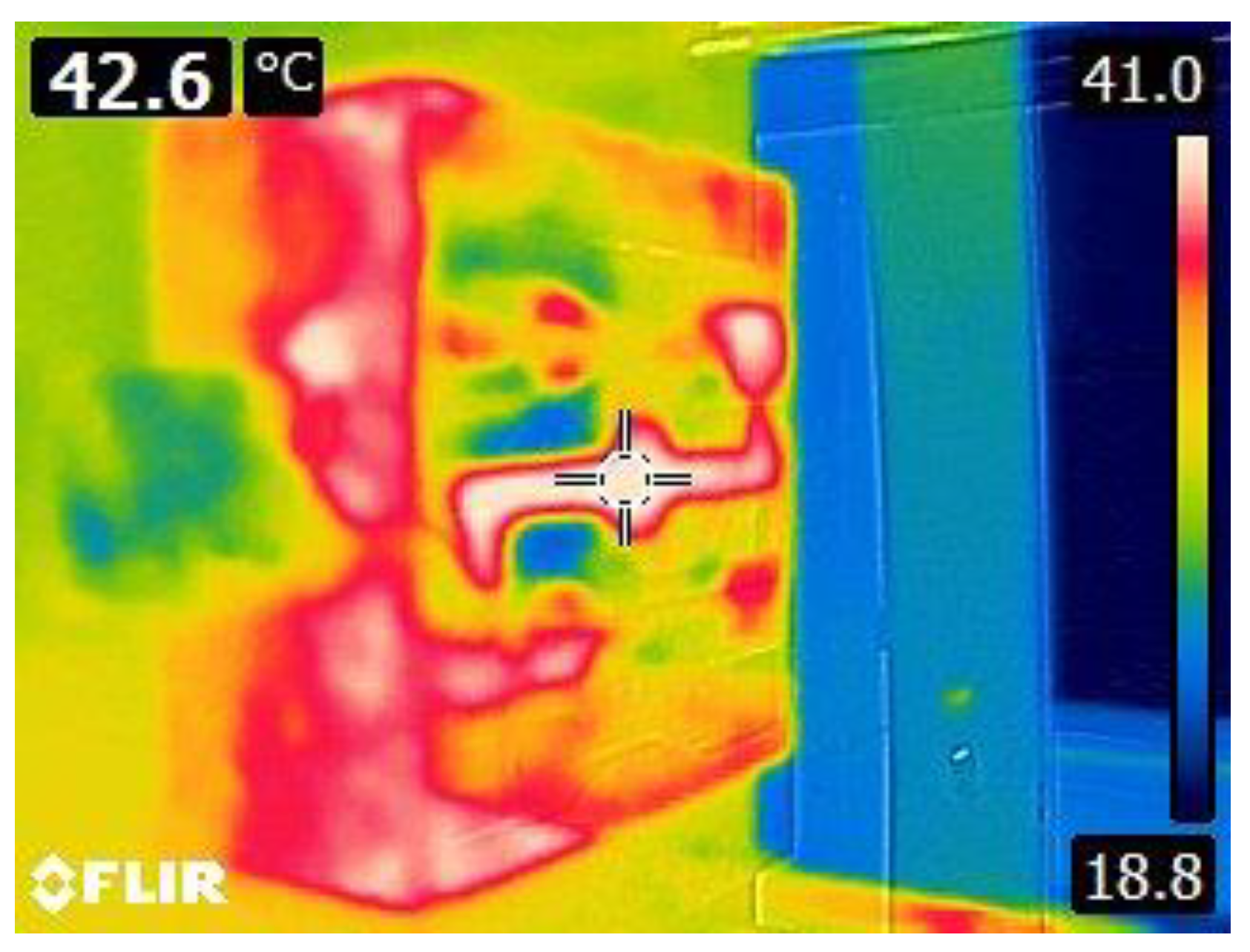
In this study, all inserts were sanded to remove excessive warpage and to ensure an optimum fitting in the bolster, and to minimise flash. Hopkins et al. reported that some warpage is expected for 3D-printed mould inserts manufactured through SLA [24]. The inner region of runners, gates and cavities was not altered. After initial moulding conditions were reached for the steel mould, these settings were used for moulding parts using the 3D-printed inserts. Thermal imaging was expected to show the temperature profile as a function of the shot number, allowing to establish a correlation between the cavity temperature and the moulded part’s properties. Moulding with the standard steel insert was performed without issues as there was little if any flash or part warpage following moulding, and the cavity temperature was recorded as 42.6 °C after 20-25 shots (Figure 2).
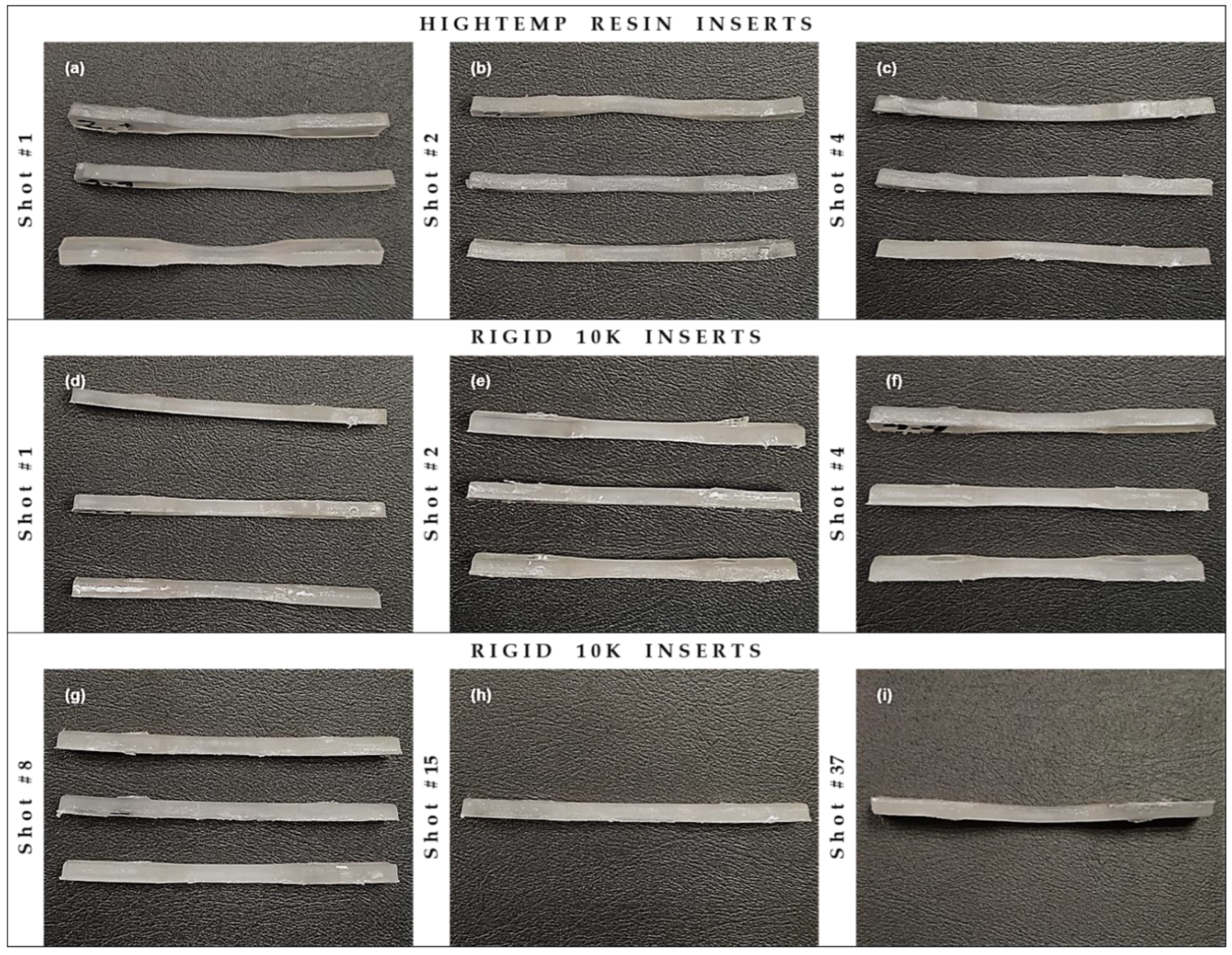
Regarding moulding with the 3D-printed inserts, sometimes the moulded parts would get stuck in the insert, meaning that manual intervention was required to extract the specimens from the insert. This costed extra time between each moulding cycle, allowing the insert to cool down for longer than expected, which in turn reflects in initiating the next cycle at a lower insert temperature than that that would be reached if the specimens weren’t stuck. The HighTemp inserts withstood 3, 4, 5 and 6 moulding cycles before failure due to cracking; although one of the inserts failed at the third cycle, it was possible to mould one more PP shot before the insert collapsed. Some flash was noticed on the moulded parts, and both warpage and sink marks were observed for all the parts produced. Warpage and sink marks are issues attributed to defective cooling or ejection [25]. Warpage on the moulded parts was also observed to increase as the number of shots rose (Figure 3), indicating poor heat extraction from the molten PP and insufficient cooling of the cavity between each shot. The Rigid 10k inserts withstood 2, 10, 11 and 37 moulding cycles before failure; although one of the inserts failed at the second cycle, it was possible to keep moulding up to the eighth shot before the insert catastrophically burst. Three of the four Rigid 10k inserts presented significant flash, but warpage on the moulded parts was minimal (Figure 3).
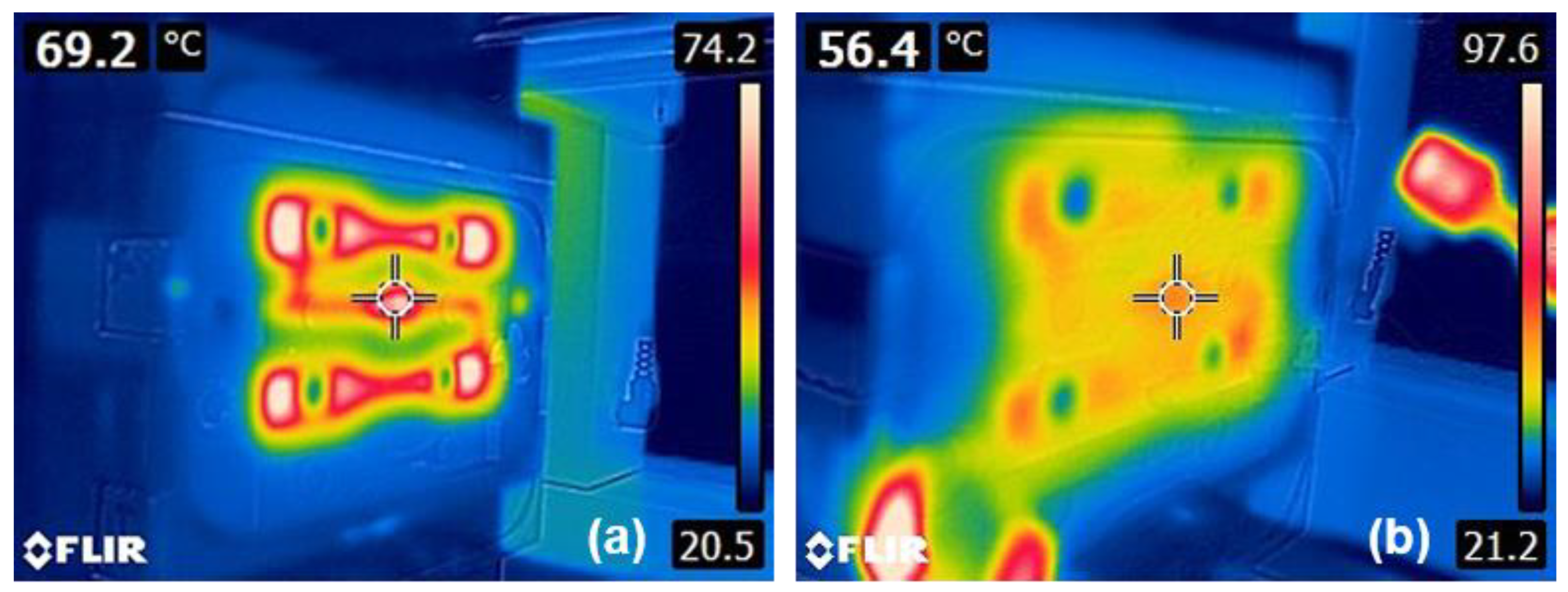
For HighTemp inserts, thermal imaging indicated that the cavities were at room temperature (ca. 23 ± 2 °C) prior to start moulding, reaching temperatures as high as 75.1 °C after two shots for one of the inserts, maintaining an average of 67.1 °C (Figure 4a). Thermal imaging of Rigid 10k inserts showed that the insert cavities reached 43.3 °C after the first shot. This temperature increased to a maximum of 56.4 °C at the fifteenth shot for the mould which enabled 37 cycles before failure (Figure 4b). In addition, heat build-up in HighTemp inserts was observed around the moulded parts only, whilst for Rigid 10k the heat build-up spread throughout the insert. This probably relates to better heat dissipation, suggesting that, although glass fibres are also a thermal insulator material, they contribute to improving the heat extraction from the molten PP—as evidenced by the dramatically reduced warpage observed—and the lower maximum cavity temperatures recorded. Nevertheless, as aforementioned some samples got stuck, thus it would not be reflective of the data to plot it in terms of cavity temperature as a function of moulding cycle.
Prior investigations with similar methodologies have aimed to measure the instant temperature at the cavities during the moulding cycles, however employing K-type thermocouples instead of thermal imaging. Using an acrylic-epoxy photoresin with k = 0.3 W·m−1·K−1, Dempsey et al. (2020) encountered a maximum temperature of 101.8 °C during injection for PP melt at 195 °C and insert at 65 °C, reaching 90–100 °C at the cavity after 10 s cooling, in comparison to the temperature of ca. 70 °C obtained with a steel mould after the same cooling period [12]. Likewise, Ribeiro et al. (2004) measured maximum cavity temperatures between 76 and 88 °C, depending on the mould temperature set—varying from 60 to 80 °C—, during the injection cycle for moulding PP melt at 185 °C [7]. Such results indicate that using filled photopolymer resins for 3D-printed mould inserts would potentially facilitate overcoming the excessive heat build-up issue. Zink et al. (2019) also studied the heat dissipation pattern of 3D-printed inserts, made of unfilled photocurable epoxy resins, including one type of insert with conventional cooling channels and another type without any forced cooling [18]. The latter showed a heat dissipation pattern similar to that of Figure 4a, whilst the former is comparable to the heat dissipation exhibited by Rigid 10k resin (Figure 4b), suggesting that this glass fibre-filled material is able to extract heat from the molten PP as efficiently as a mould insert with cooling channels.
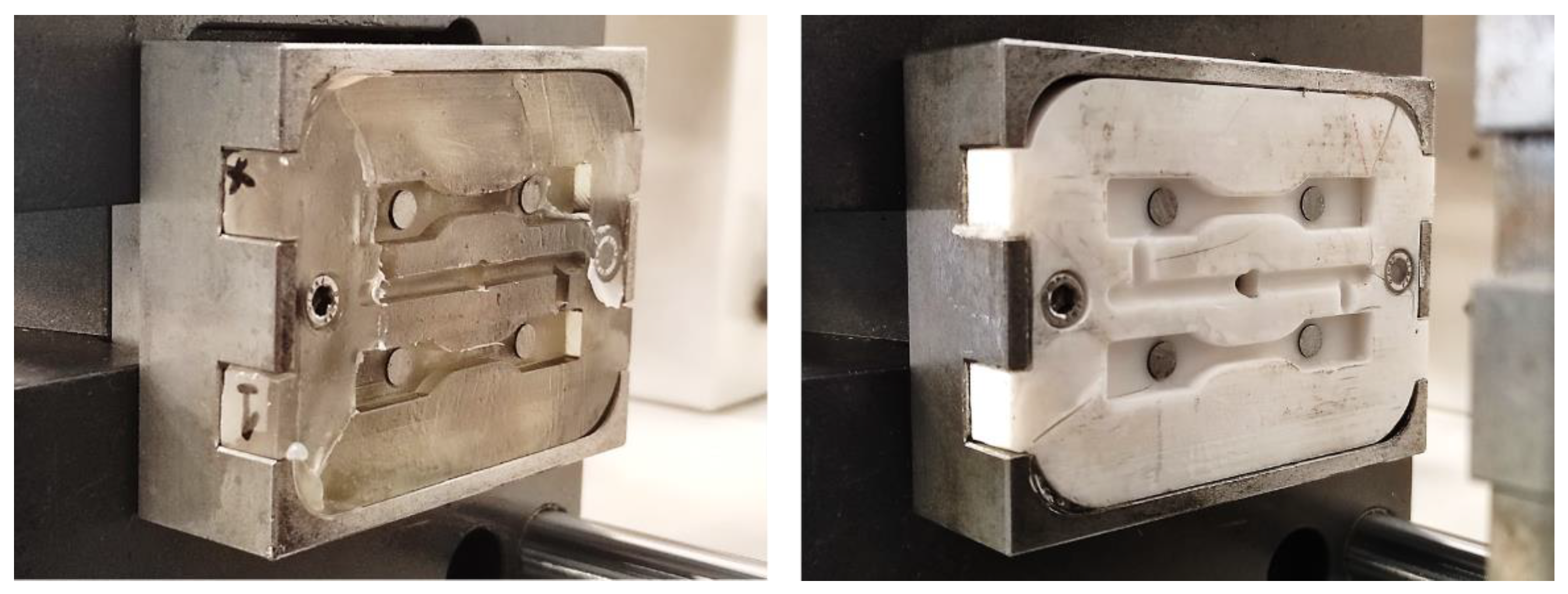
Moreover, for inserts made of both the photopolymer resins, cracks were observed to span from any two ejector pins and between each other, and then span radially to the closest edge (Figure 5). A reason for that would be a stress concentration in the area between the ejector pins due to some degree of warpage of the inserts themselves, resulting in an uneven surface from the edges towards the centre. HighTemp inserts broke brittlely into several pieces, whilst Rigid 10k inserts split into two parts only, unveiling distinct modes of energy storage and the introduction of toughening mechanisms, likely due to the latter resin being filled with glass fibres [26,27,28]. Also, Rajaguru et al. (2015) and Dempsey et al. (2020) associate the insert durability with both the melt temperature and the induced pressure, as these factors may affect directly the mechanical performance, reducing the storage modulus [12,29].

3.2. Thermal and Mechanical Properties of the Photopolymer Resins

DMA indicates that Rigid 10k photopolymer resin has superior mechanical properties and higher Tg in comparison to HighTemp resin. The viscoelastic properties of each material are presented in Table 2 and Figure 6. At room temperature, E’ of Rigid 10k resin is four times greater than that of HighTemp.
At the maximum cavity temperatures recorded with the IR thermal camera during the moulding cycles for HighTemp and Rigid 10k insert materials, respectively 75.1 and 56.4 °C, E’ exhibited values of 479.2 and 4495.8 MPa, representing a nearly ten-times difference. In addition, the E’ values are validated by the analogous Young’s modulus [21,22]. Tg also presented a sharp difference between the insert materials, being ca. 45 °C higher for the glass fibre-containing resin. Rigid 10k resin presented a secondary Tg at 93.7 °C, which suggests that the polymeric fraction of the material actually consists of a blend of two different photopolymer resins. Zhao et al. (2015) studied mixtures of acrylate- and epoxy-based photopolymerisable resins for SLA and demonstrated the occurrence of two separate Tg’s for a single blend, each one associated with one of the UV-sensitive monomers [30].
Rigid 10k and HighTemp materials exhibited thermal conductivities of 0.83 and 0.63 W·m−1·K−1, respectively, revealing a less heat-resistive behaviour of the former. The thermal conductivity of steel usually lies between 45–66 W·m−1·K−1 [31,32], a gigantic difference in comparison to polymer materials, which reflects in distinct cooling rates that can be achieved by each mould or insert. Depending on the crystallisation kinetics of the plastic to be moulded, slow cooling rates may cause the degree of crystallinity to increase, whilst rapid cooling rates prevent shrinkage and assist in reducing the injection cycle time [15,16,17,33]. This is crucial when determining the throughput or productivity rate, as the shorter the cooling time, the greater the number of manufactured parts. Therefore, it is of major importance to find a balance between the cooling rate and the final part’s required performance; however, extracting heat still remains critical [34,35,36]. For instance, Mendible et al. (2017) compared metallic inserts to a photopolymer-based one (k = 0.3 W·m−1·K−1) and found out that the total cycle time increased from 45 s to 200 s, leading to a slower cooling rate which caused both the shrinkage and degree of crystallinity to increase [19].
Furthermore, Shore D hardness measurements are crucial for assessing the performance of surface properties. HighTemp resin presented a hardness value of 80.7 Shore D, while for Rigid 10k it was 12.5% greater at 90.8, which are similar to values previously reported in the literature [37,38]. Adding filler particles changes the microstructure of the polymeric matrix and introduces grain boundaries causing the composite to reach greater hardness values [37]. Both thermal conductivity and Shore D testing results indicate that there is a significant difference in the materials’ characteristics, as ANOVAs were performed and resulted p < 0.05 at a confidence level of 95%.

3.3. PP Thermal Characteristics

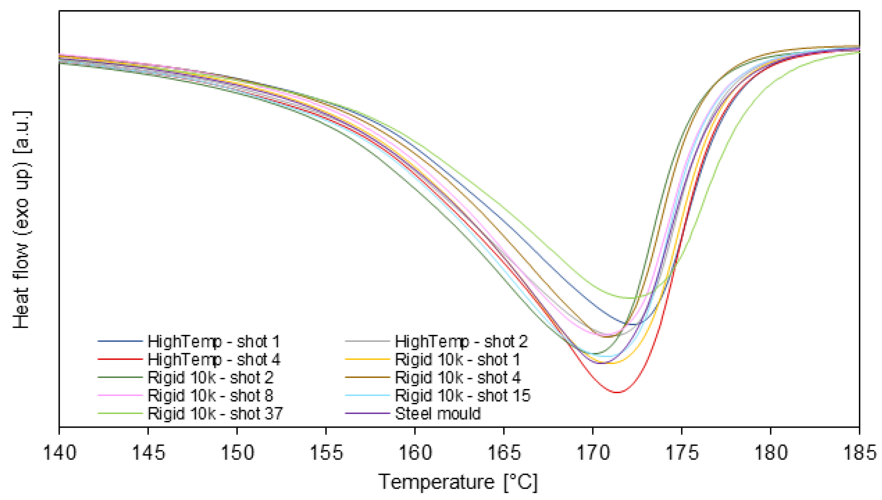
DSC was carried out to investigate the thermal behaviour of PP samples produced in the steel mould and in the polymeric inserts. The melting temperature and the crystallinity content were evaluated considering the first heating step, as the objective is to assess the effect of the IM cooling stage on the moulded parts’ properties. Thermal transitions features and degree of crystallinity are presented in Table 3, and thermograms are shown in Figure 7 and Figure 8. Melting point, enthalpy of fusion, degree of crystallinity, crystallisation temperature and enthalpy of crystallisation are respectively represented by Tm, ∆Hf, %Xc, Tc and ∆Hc.
Results from three shots of PP samples moulded using HighTemp showed a single endothermic peak ranging from 170.7 to 171.6 °C which is related to the crystalline melting, with ΔHf from 83.9 to 87.1 J·g−1, %Xc from 40.2 to 41.7%, melt crystallisation peak temperature from 109.9 to 110.3 °C, and ΔHc from 133.6 to 139.3 J·g−1. Moreover, six shots of PP samples moulded using Rigid 10k also demonstrated an endothermic melting peak ranging from 170.1 to 172.1 °C, ΔHf from 84.0 to 87.3 J·g−1, %Xc from 39.3 to 41.8%, Tc 109.5 to 110.1 °C, and ΔHc from 129.7 to 139.1 J·g−1.
Comparison of results obtained for different shots in the HighTemp inserts reveals that there is a quick increase of both melting enthalpy and crystallinity degree, which later stabilise. This is likely due to the observed poor heat dissipation between each moulding cycle. As such, the HighTemp inserts accumulate thermal energy since the first moulding cycle and are unable to transfer it efficiently, as demonstrated by the infrared imaging (Figure 4a) and the lower thermal conductivity, thus leading to cooling conditions favourable to crystallisation. On the other hand, this effect is not noticed for Rigid 10k inserts, since this material presents greater thermal conductivity and lower maximum cavity temperature, enabling better heat extraction from the molten PP. This is reflected in a slower increase rate of melting enthalpy and crystallinity degree, which are closer to those of samples moulded in the conventional steel mould.
Additionally, observations on the melting region of the thermograms, as highlighted in Figure 9, indicate minimal changes in the fusion peaks, having similar sharpness, width, intensity and onset point. Although the cavity temperature is increasing after each moulding cycle, this does not express a major change in melting enthalpy and crystallinity degree—however, it affects other characteristics such as mechanical properties and warpage—, supporting the hypothesis of the unpredictability of microstructure as an outcome due to moulding the PP parts either in any of the 3D-printed polymer-based inserts, as previously proposed in the literature [24,35,36,39].
Contrastingly, previous work by Hopkins et al. (2021) had found an increase of ca. 20% in the crystallinity degree of PP when utilising polymer-based 3D-printed inserts in comparison to steel mould [24]. Although that study had a very similar methodology, differences arise from employing different conditions: Hopkins et al. (2021) carried out their experiments using a 30 s cooling step at every moulding cycle, and the steel mould temperature was kept at 30 °C whilst a compressed air forced chilling was applied to the surface of all inserts for 60 s after every cycle. Also, that investigation utilised a PP grade reportedly containing a nucleating agent to ensure rapid crystallisation, which is not the case herein [20,24]. As the present work was designed to measure heat build-up and its effect on the properties of the moulded parts, it used a moulding cycle with an 18 s cooling step, keeping the steel mould temperature at 40 °C and without any surface forced chilling, hence less time was available for the PP samples to cool down. It becomes clear that this depicts a combination of factors likely to cause distinct cooling conditions, hence leading to thermal and physical properties variations [16,17,24,33,39]. Furthermore, slow cooling rates cause the crystallinity to increase as the material’s inner regions keep warm, then allowing further crystallisation. Mendible et al. (2017) also reported an increase in both shrinkage and degree of crystallinity due to a slower cooling rate in the polymeric insert compared to that of the metallic inserts [19].

3.4. PP Mechanical Properties and Dimensional Stability

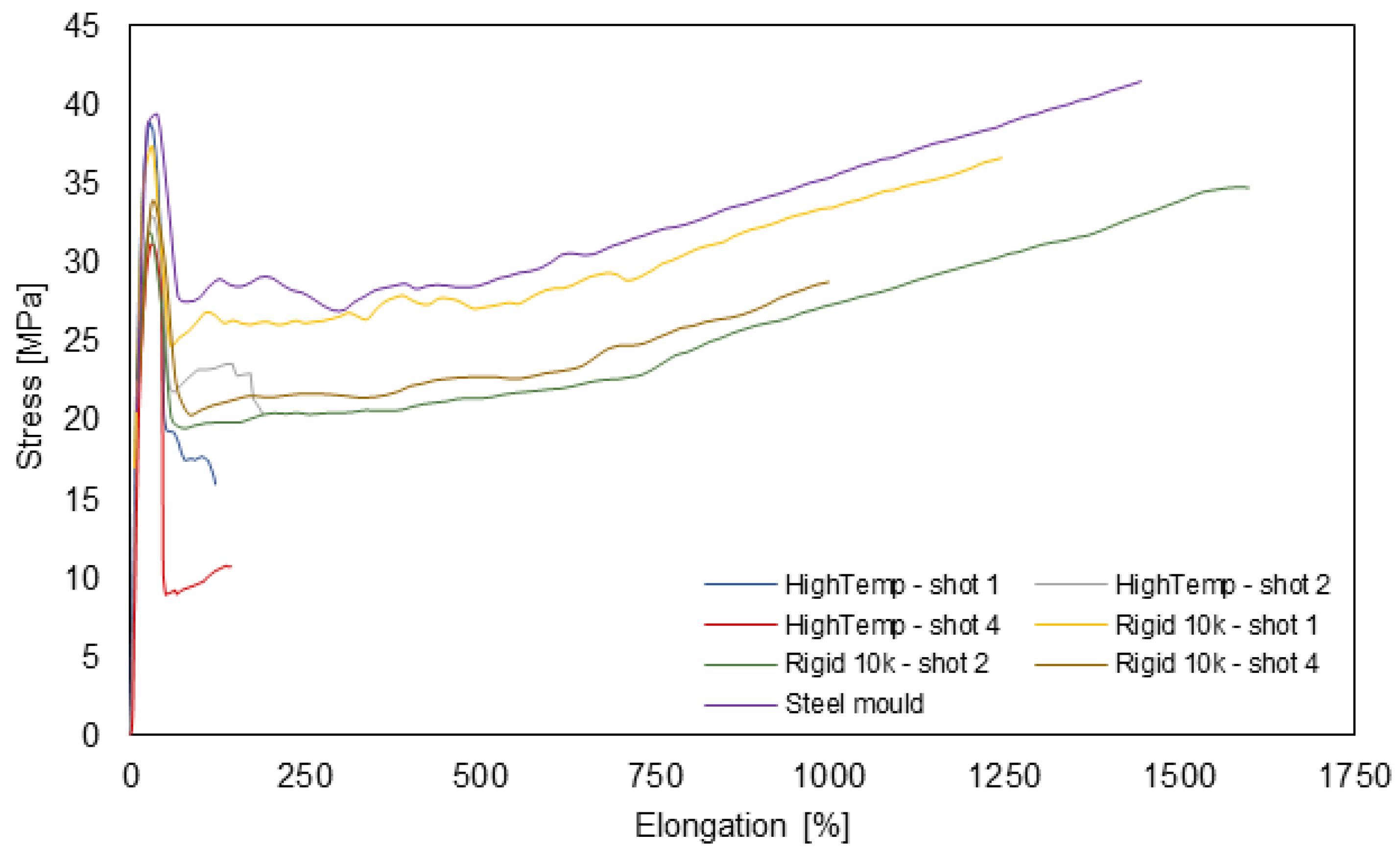
Mechanical testing results suggest that there is no significant effect on the mechanical properties evaluated due to moulding the PP parts either in the steel mould or in one of the 3D-printed polymer-based inserts, except for elongation at break (Figure 10 and Table 4). Young’s modulus, the ultimate tensile strength and the stress at break exhibited only fluctuations around their respective averages, respectively ranging from 261.0 to 310.8 MPa, 32.1 to 42.9 MPa and 1.6 to 6.2 MPa, with no significant differences, as indicated by the analyses of variance performed, with p > 0.05. Conversely, for the elongation at break, it was noticed that the mould material has a significant effect (p < 0.05). In this case, the specimens from the steel mould and the Rigid 10k insert have elongation at break differences within the critical limit, therefore being considered statistically indistinguishable according to the Tukey’s test; however, specimens moulded in HighTemp insert presented significant differences when compared to the other mould materials through the Tukey’s test.
It is well known that the elongation is directly related to the polymers’ degree of crystallinity, so once the crystalline content increases under influence of the slower cooling, it would be expected to increase in elongation. Nevertheless, it was observed a reduction in elongation, supporting the hypothesis that the polymer crystalline segments were disordered within the amorphous phase, hence leading to a highly unpredictable semicrystalline polymeric material [24]. As the crystalline structure is easily influenced by temperature and the cooling rate, which may favour the β-crystal formation due to poor cooling rate [19,39], this would change the material toughness response. In other words, it has been observed that, although the degree of crystallinity of samples moulded in HighTemp inserts was kept at the same level as the other ones, it was not enough to maintain elevated strain at break, likely due to a different microstructure resulting from the defective cooling.
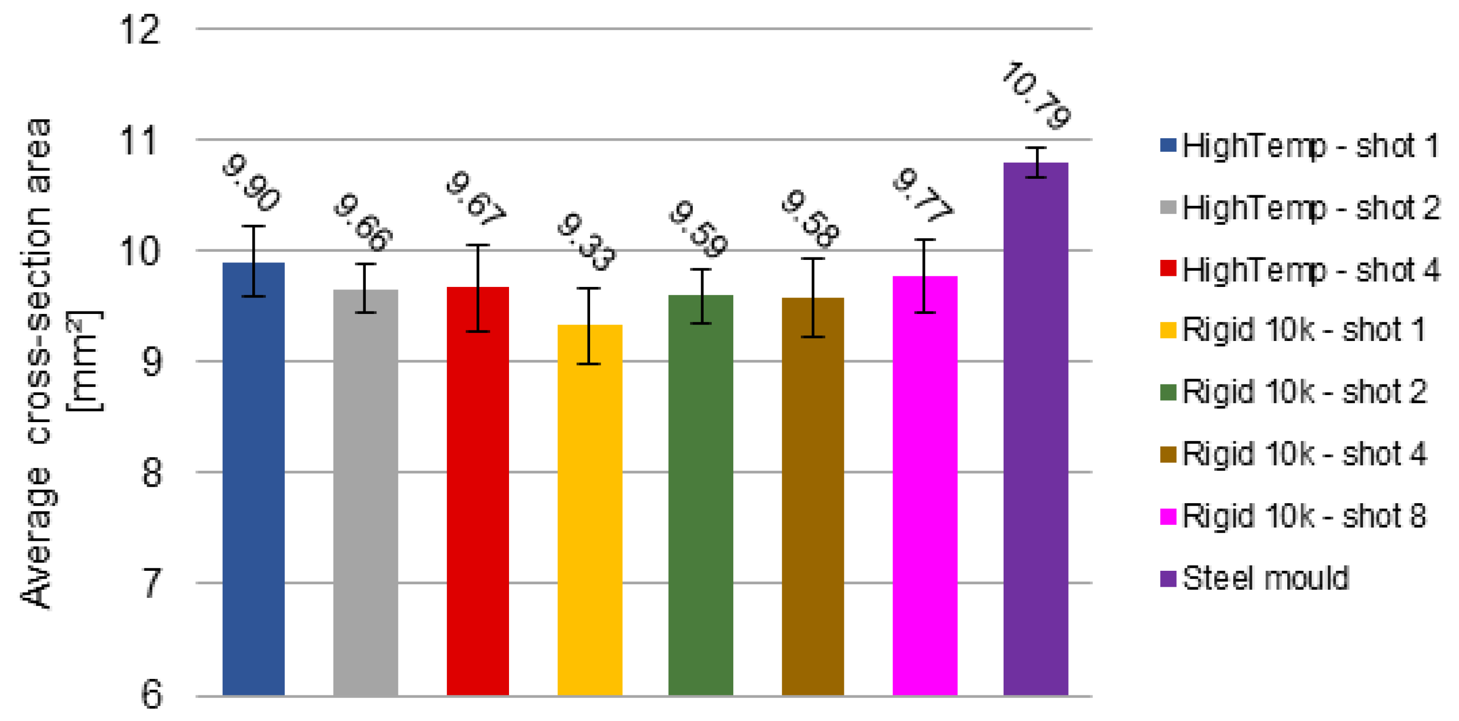
The thermal dimensional stability of the moulded parts was assessed through the cross-section areas of the specimens’ narrow section, which are presented in Figure 11. The average measurements for each sample group range between 9.33 (Rigid 10k—shot 1) and 10.87 mm2 (Steel mould). It’s noteworthy draws attention that all the parts moulded with 3D-printed mould inserts had a considerable reduction in cross-section area in comparison to that of PP specimens made in the steel mould. The increase in shrinkage due to a slower cooling rate in polymeric inserts compared to that of the metallic inserts has already been reported in the literature, being mainly related to cavity temperature, cooling rate, and hold pressure [12,19,39]. Moreover, another factor influencing the geometry of the moulded parts is the dimensional stability of the insert itself. Deviations in the geometry of the 3D-printed parts arise due to overexposure and compression of the first layers and due to resolution limitations of the printing system, as reported by Dempsey et al. (2020) [12], as well as due to the deformation of the insert caused by the injection pressure, as reported by Martinho et al. [39].
ASTM D638 type V tensile specimens have a nominal narrow-section cross-section area of 10.11 mm2 (l = 3.18 mm). According to Martinho et al. (2009), the expected linear shrinkage for a semicrystalline polymer usually ranges from 1.0 to 2.5% [39]. Thus, allowing for the maximum linear shrinkage expected, the cross-section area would be ca. 9.61 mm2. This reveals that the PP parts produced with the steel mould actually expanded, instead of shrinking. On the other hand, three sample groups (Rigid 10k—shots 1, 2 and 4) exhibited average cross-section areas with differences beyond the expected (Table 5); nevertheless, if the standard-deviations are to be considered for these samples, then they could meet the expected spatial shrinkage tolerance.
For specimens moulded in HighTemp resin inserts, an inverse but analogous trend to that of degree of crystallinity was noticed: the cross-section area reduces and then stabilises as the %Xc increases and then stabilises (Table 3). This suggests an association between the crystallinity content and the geometrical features of such specimens, as it was also observed through the occurrence of sink marks and warpage. As the HighTemp inserts face poor thermal conduction (Figure 4), they accumulate heat in the cavities since the first moulding cycle. Mendible et al. (2017) reported that the shrinkage of PP parts moulded in 3D-printed polymer-based inserts was greater than the predicted, and increased with the moulding cycle, which was mainly attributed to the effects of thermal expansion changing the cavity dimensions [19]. Thus, the effects of the insufficient heat extraction combine with the mould insert’s geometry thermal stability, causing the crystallinity and the cavity’s changing dimension to drive the dimensional stability of these PP specimens.
On the other hand, PP parts moulded with Rigid 10k inserts showed a different behaviour: the cross-section area tended to increase with the moulding cycle, decreasing the shrinkage. Contrasting to HighTemp inserts, the Rigid 10k ones are favoured with greater heat dissipation as observed by thermal imaging (Figure 4). In this case, an association between the geometrical stability of the cross-section area and the crystallinity content is not possible. Due to the higher thermal conductivity imparted by the glass fibres (Table 2), the cavity zone takes longer to accumulate heat and enables more efficient cooling of the molten PP. This allows the insert’s dimensional deviations from the 3D-printing plus the insert deflection by the injection pressure to combine with the moulding polymer intrinsic shrinkage, as proposed by Martinho et al. (2009) [39]—thus overcoming the thermal expansion and crystallisation effects.

4. Conclusions

This experimental study was carried out aiming to investigate the feasibility of using two different photopolymer resins (FormLabs HighTemp and FormLabs Rigid 10k) to fabricate 3D-printed mould inserts to replace traditional steel moulds, and to verify whether the thermal and mechanical properties of the moulded PP are comparable to those of the steel mould. Furthermore, the IM process was studied to assess the cavity heat build-up and its effects on the melt and the moulded parts quality. Based on the results obtained, the following conclusions can be made:
The mould inserts manufactured through SLA presented occasional warpage without any alteration in the inner region of runners, gates and cavities. The Rigid 10k inserts withstood more moulding cycles before failure than the HighTemp inserts. Also, the parts produced using both IM inserts displayed some degree of flash, warpage and sink marks.
Dynamic mechanical analysis suggests that Rigid 10k has superior mechanical properties and higher Tg in comparison to HighTemp. E’ of Rigid 10k resin was four times greater than that of HighTemp at room temperature and nearly ten times greater at the maximum cavity temperatures. A sharp difference was also noticed in the glass transitions of both insert materials.
The thermal conductivity of Rigid 10k was greater than that of HighTemp, indicating that the latter is more heat-resistive than Rigid 10k.
Calorimetric results obtained for different shots and moulds revealed that the thermal properties and degree of crystallinity of PP varied due to the effect of the different cooling conditions. There was a quicker increase of those characteristics between shots for PP parts moulded in HighTemp inserts due to poorer heat dissipation.
The study of PP mechanical properties suggests that there is no significant effect on all the features evaluated except for the elongation at break, which supports the hypothesis that the polymer crystalline domains were disordered within the amorphous phase leading to a highly unpredictable semicrystalline polymeric material, causing a reduction in elongation.
Overall, these findings endorse the further application of SLA mould inserts for the manufacturing of injection-moulded plastic parts when it is the case of prototypes or small batches. The cost-effectiveness of AM moulds is very attractive when applied to product-development stages, with uncountable factors involved not only in the cost but also in design, commissioning and fabrication, contributing to the feasibility and affordability of employing this approach in an industrial setting. Results would be further improved with the incorporation of cooling channels which can easily be incorporated into the 3D printed design.

Author Contributions

Conceptualization, V.F.M., E.F., C.H. and D.M.D.; Data curation, V.F.M. and S.G.; Formal analysis, V.F.M. and D.M.D.; Funding acquisition, J.G.L. and D.M.D.; Investigation, V.F.M. and G.S.N.B.; Methodology, V.F.M., M.H.J., E.F., S.G., C.H. and D.M.D.; Project administration, J.G.L. and D.M.D.; Resources, J.G.L. and D.M.D.; Supervision, D.M.D.; Validation, V.F.M. and G.S.N.B.; Visualization, V.F.M.; Writing—original draft, V.F.M. and G.S.N.B.; Writing—review & editing, V.F.M., G.S.N.B. and D.M.D. All authors have read and agreed to the published version of the manuscript.

Funding

This publication has results from research conducted with the financial support of Enterprise Ireland under the Technology Gateway Programme, Grant Number TG-2017-0114 (APT Ireland), and Science Foundation Ireland (SFI), Grant Number SFI 16/RC/3918, cofunded by the European Regional Development Fund. The APC was funded by Science Foundation Ireland (SFI), Grant Number SFI 16/RC/3918.

Institutional Review Board Statement

Not applicable.

Informed Consent Statement

Not applicable.

Data Availability Statement

All data necessary to reproduce the results and support the conclusions are included within this paper.

Acknowledgments

Authors would like to thank the APT Ireland staff for assisting with the injection moulding processes.

Conflicts of Interest

The authors declare no conflict of interest.

References

  1. Singh, G.; Verma, A. A Brief Review on injection moulding manufacturing process. Mater. Today Proc. 2017, 4, 1423–1433. [Google Scholar] [CrossRef]
  2. Maddah, H.A. Polypropylene as a Promising Plastic: A Review. Am. J. Polym. Sci. 2016, 6, 1–11. [Google Scholar] [CrossRef]
  3. Petrova, T.; Kazmer, D. Incorporation of Phenomenological Models in a Hybrid Neural Network for Quality Control of Injection Molding. Polym. Plast. Technol. Eng. 1999, 38, 1–18. [Google Scholar] [CrossRef]
  4. Levy, G.N.; Schindel, R.; Kruth, J.P. Rapid manufacturing and rapid tooling with layer manufacturing (LM) technologies, state of the art and future perspectives. CIRP Ann. 2003, 52, 589–609. [Google Scholar] [CrossRef]
  5. Yap, Y.L.; Wang, C.; Sing, S.L.; Dikshit, V.; Yeong, W.Y.; Wei, J. Material jetting additive manufacturing: An experimental study using designed metrological benchmarks. Precis. Eng. 2017, 50, 275–285. [Google Scholar] [CrossRef]
  6. Pouzada, A.S. Hybrid moulds: A case of integration of alternative materials and rapid prototyping for tooling. Virtual Phys. Prototyp. 2009, 4, 195–202. [Google Scholar] [CrossRef]
  7. Ribeiro, A.S.; Hopkinson, N.; Ahrens, C.H. Thermal effects on stereolithography tools during injection moulding. Rapid Prototyp. J. 2004, 10, 176–180. [Google Scholar] [CrossRef] [Green Version]
  8. Westphal, M.G.; Pouzada, A.S.; Salmoria, G.V.; Ahrens, C.H. Performance and Friction Properties of Injection Hybrid Moulds with Stereolithography Moulding Zones. Mater. Sci. Forum. 2006, 514–516, 1673–1677. [Google Scholar] [CrossRef]
  9. Rahmati, S.; Dickens, P. Rapid tooling analysis of Stereolithography injection mould tooling. Int. J. Mach. Tools Manuf. 2007, 47, 740–747. [Google Scholar] [CrossRef]
  10. Martinho, P.; Bártolo, P.J.; Queirós, L.M.P.; Pontes, A.J.; Pouzada, A.S. Hybrid moulds: The use of combined techniques for the rapid manufacturing of injection moulds. In Virtual Modeling and Rapid Manufacturing: Advanced Research in Virtual and Rapid Prototyping: Proceedings of the 2nd International Conference on Advanced Research and Rapid Prototyping, Leiria, Portugal, 28 September–1 October 2005; Taylor and Francis: New York, NY, USA, 2005; Available online: http://hdl.handle.net/1822/34152 (accessed on 20 July 2022).
  11. Gheisari, R.; Bartolo, P.; Goddard, N.; Domingos, M.A.N. An experimental study to investigate the micro-stereolithography tools for micro injection molding. Rapid Prototyp. J. 2017, 23, 711–719. [Google Scholar] [CrossRef]
  12. Dempsey, D.; McDonald, S.; Masato, D.; Barry, C. Characterization of Stereolithography Printed Soft Tooling for Micro Injection Molding. Micromachines 2020, 11, 819. [Google Scholar] [CrossRef]
  13. Roy, M.; Dickens, T.J. Additive technology of soluble mold tooling for embedded devices in composite structures: A study on manufactured tolerances. Addit. Manuf. 2017, 15, 78–86. [Google Scholar] [CrossRef] [Green Version]
  14. Pervaiz, S.; Qureshi, T.A.; Kashwani, G.; Kannan, S. 3D Printing of Fiber-Reinforced Plastic Composites Using Fused Deposition Modeling: A Status Review. Materials 2021, 14, 4520. [Google Scholar] [CrossRef]
  15. Wu, T.; Jahan, S.A.; Zhang, Y.; Zhang, J.; Elmounayri, H.; Tovar, A. Design Optimization of Plastic Injection Tooling for Additive Manufacturing. Procedia Manuf. 2017, 10, 923–934. [Google Scholar] [CrossRef]
  16. Natalini, M.; Sasso, M.; Amodio, D. Comparison of Numerical and Experimental Data in Multi-objective Optimization of a Thermoplastic Molded Part. Int. Polym. Process. 2013, 28, 84–106. [Google Scholar] [CrossRef]
  17. Farotti, E.; Natalini, M. Injection molding. Influence of process parameters on mechanical properties of polypropylene polymer. A first study. Procedia Struct. Integr. 2018, 8, 256–264. [Google Scholar] [CrossRef]
  18. Zink, B.; Kovács, N.K.; Kovács, J.G. Thermal analysis based method development for novel rapid tooling applications. Int. Commun. Heat Mass Transf. 2019, 108, 104297. [Google Scholar] [CrossRef]
  19. Mendible, G.A.; Rulander, J.A.; Johnston, S.P. Comparative study of rapid and conventional tooling for plastics injection molding. Rapid Prototyp. J. 2017, 23, 344–352. [Google Scholar] [CrossRef]
  20. SASOL. Polypropylene Homopolymer (HNR100). 2017. Available online: https://products.sasol.com/pic/products/home/grades/ZA/5hnr100/index.html (accessed on 20 July 2022).
  21. FormLabs. HighTemp Resin. 2018. Available online: https://formlabs-media.formlabs.com/datasheets/High_Temp_Technical.pdf (accessed on 20 July 2022).
  22. FormLabs. Rigid 10k Resin. 2020. Available online: https://formlabs-media.formlabs.com/datasheets/2001479-TDS-ENUS-0.pdf (accessed on 20 July 2022).
  23. Wang, K.; Bahlouli, N.; Addiego, F.; Ahzi, S.; Rémond, Y.; Ruch, D.; Muller, R. Effect of talc content on the degradation of re-extruded polypropylene/talc composites. Polym. Degrad. Stab. 2013, 98, 1275–1286. [Google Scholar] [CrossRef]
  24. Hopkins, M.; Gunbay, S.; Hayes, C.; Moritz, V.F.; Fuenmayor, E.; Lyons, J.G.; Devine, D.M. Stereolithography (SLA) utilised to print injection mould tooling in order to evaluate thermal and mechanical properties of commercial polypropylene. Procedia Manuf. 2021, 55, 205–212. [Google Scholar] [CrossRef]
  25. Solanki, B.S.; Sheorey, T.; Singh, H. Experimental and numerical investigation of shrinkage and sink marks on injection molded polymer gears: A case study. Int. J. Interact. Des. Manuf. 2022. [Google Scholar] [CrossRef]
  26. Lassila, L.; Garoushi, S.; Vallittu, P.K.; Säilynoja, E. Mechanical properties of fiber reinforced restorative composite with two distinguished fiber length distribution. J. Mech. Behav. Biomed. Mater. 2016, 60, 331–338. [Google Scholar] [CrossRef]
  27. Ebrahimnezhad-Khaljiri, H.; Eslami-Farsani, R. The tensile properties and interlaminar shear strength of microcapsules-glass fibers/epoxy self-healable composites. Eng. Fract. Mech. 2020, 230, 106937. [Google Scholar] [CrossRef]
  28. Saravanakumar, K.; Arumugam, V.; Souhith, R.; Santulli, C. Influence of Milled Glass Fiber Fillers on Mode I & Mode II Interlaminar Fracture Toughness of Epoxy Resin for Fabrication of Glass/Epoxy Composites. Fibers 2020, 8, 36. [Google Scholar] [CrossRef]
  29. Rajaguru, J.; Duke, M.; Au, C. Development of rapid tooling by rapid prototyping technology and electroless nickel plating for low-volume production of plastic parts. Int. J. Adv. Manuf. Technol. 2015, 78, 31–40. [Google Scholar] [CrossRef]
  30. Zhao, Y.; Yang, M.; Ding, R.; Shi, Q.; Zhao, M. Preparation of a hybrid photopolymer for stereolithography. In Proceedings of the 5th International Conference on Advanced Design and Manufacturing Engineering—ICADME 2015, Shenzhen, China, 19–20 September 2015; pp. 1628–1632. [Google Scholar] [CrossRef]
  31. Hassanzadeh-Aghdam, M.K.; Mahmoodi, M.J.; Safi, M. Effect of adding carbon nanotubes on the thermal conductivity of steel fiber-reinforced concrete. Compos. Part B Eng. 2019, 174, 106972. [Google Scholar] [CrossRef]
  32. Mulyana, T.; Rahim, E.A.; Yahaya, S.N.M. The influence of cryogenic supercritical carbon dioxide cooling on tool wear during machining high thermal conductivity steel. J. Clean. Prod. 2017, 164, 950–962. [Google Scholar] [CrossRef]
  33. Kusić, D.; Hančič, A. Influence of molding conditions on the shrinkage and warpage behavior of standardized test specimens. In Proceedings of the Regional Conference Graz 2015—Polymer Processing Society PPS, Graz, Austria, 21–5 September 2015; p. 020017. [Google Scholar] [CrossRef] [Green Version]
  34. Lam, Y.C.; Zhai, L.Y.; Tai, K.; Fok, S.C. An evolutionary approach for cooling system optimization in plastic injection moulding. Int. J. Prod. Res. 2004, 42, 2047–2061. [Google Scholar] [CrossRef]
  35. Gradys, A.; Sajkiewicz, P.; Minakov, A.A.; Adamovsky, S.; Schick, C.; Hashimoto, T.; Saijo, K. Crystallization of polypropylene at various cooling rates. Mater. Sci. Eng. A 2005, 413–414, 442–446. [Google Scholar] [CrossRef]
  36. Rhoades, A.M.; Wonderling, N.; Gohn, A.; Williams, J.; Mileva, D.; Gahleitner, M.; Androsch, R. Effect of cooling rate on crystal polymorphism in beta-nucleated isotactic polypropylene as revealed by a combined WAXS/FSC analysis. Polymer 2016, 90, 67–75. [Google Scholar] [CrossRef]
  37. Hu, G.; Cao, Z.; Hopkins, M.; Lyons, J.G.; Brennan-Fournet, M.; Devine, D.M. Nanofillers can be used to enhance the thermal conductivity of commercially available SLA resins. Procedia Manuf. 2019, 38, 1236–1243. [Google Scholar] [CrossRef]
  38. Hu, G.; Cao, Z.; Hopkins, M.; Hayes, C.; Daly, M.; Zhou, H.; Devine, D.M. Optimizing the hardness of SLA printed objects by using the neural network and genetic algorithm. Procedia Manuf. 2019, 38, 117–124. [Google Scholar] [CrossRef]
  39. Martinho, P.G.; Bártolo, P.J.; Pouzada, A.S. Hybrid moulds: Effect of the moulding blocks on the morphology and dimensional properties. Rapid Prototyp. J. 2009, 15, 71–82. [Google Scholar] [CrossRef]
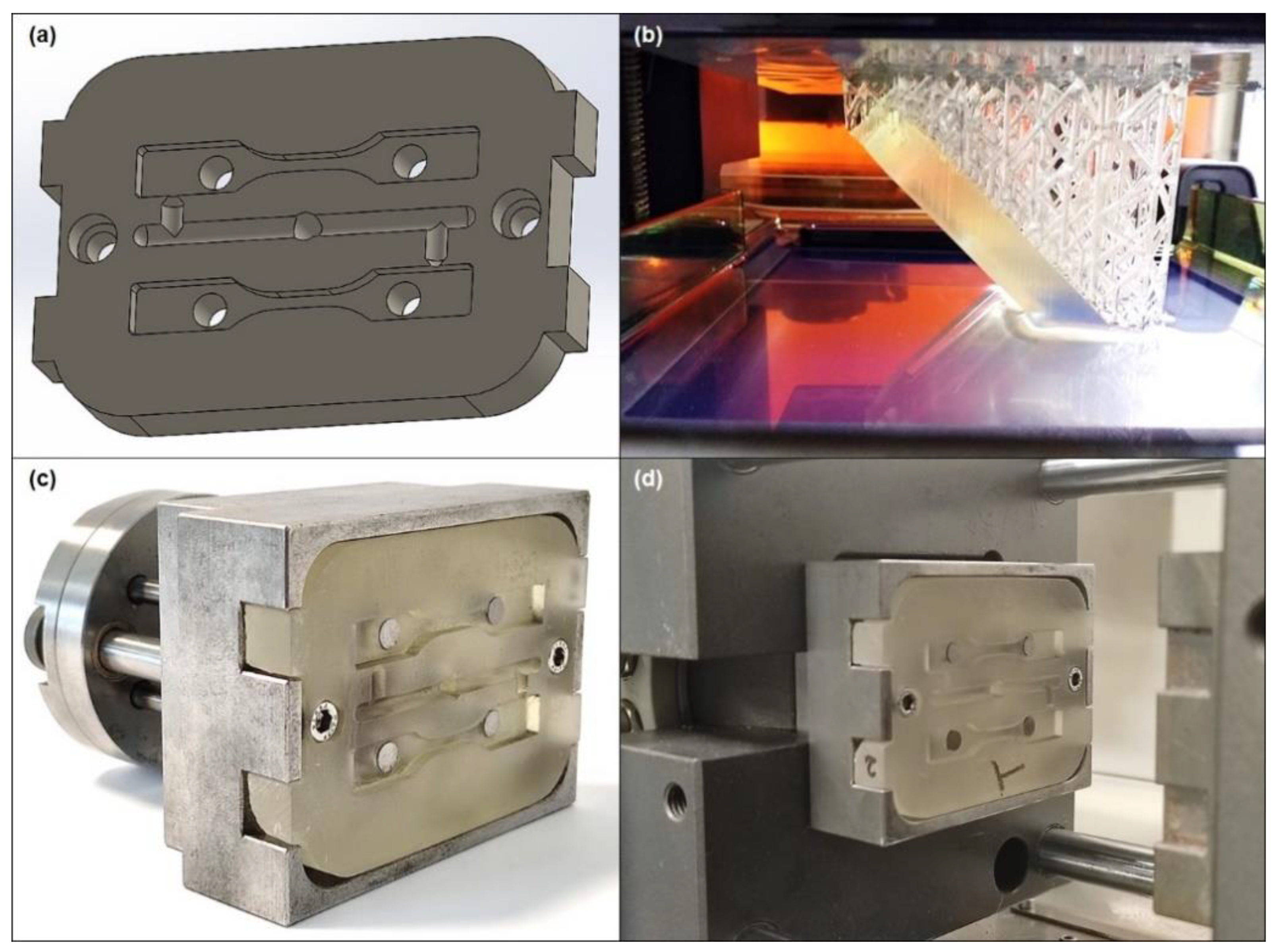
Figure 1. (a) Rendering of the mould insert designed; (b) insert while printing in the FormLabs 2 SLA 3D printer with HighTemp resin; (c) HighTemp mould insert fitting the steel bolster with the ejector system; (d) bolster containing a HighTemp insert fitted in the moulding machine.
Jmmp 06 00117 g001
Figure 2. Temperature profile of the steel mould after 23 shots.
Jmmp 06 00117 g002
Figure 3. Photographs of three specimens moulded in HighTemp inserts from (a) 1st, (b) 2nd and (c) 4th shots; and specimens moulded in Rigid 10k inserts from (d) 1st, (e) 2nd, (f) 4th, (g) 8th, (h) 15th and (i) 37th shots.
Jmmp 06 00117 g003
Figure 4. Temperature profiles of a (a) HighTemp insert and (b) a Rigid 10k insert.
Jmmp 06 00117 g004
Figure 5. Photographs of the failure modes of the different photoresin mould inserts. HighTemp inserts (left) presented a trend of breaking in a brittle manner into several pieces, whilst Rigid 10k inserts (right) had cracks spanning radially from the ejector pins to the closest edges.
Jmmp 06 00117 g005
Figure 6. Storage modulus (continuous line) and tan(δ) (dashed line) for HighTemp (blue) and Rigid 10k (red) insert materials.
Jmmp 06 00117 g006
Figure 7. DSC thermograms obtained during the heating step for PP moulded in different moulds and at different shots.
Jmmp 06 00117 g007
Figure 8. DSC thermograms obtained during the cooling step for PP moulded in different moulds and at different shots.
Jmmp 06 00117 g008
Figure 9. Comparative highlight of the melting interval from selected DSC thermograms obtained during the heating step for PP moulded in different moulds and at different shots.
Jmmp 06 00117 g009
Figure 10. Selected stress-strain curves obtained for PP specimens moulded using different tool inserts.
Jmmp 06 00117 g010
Figure 11. Cross-section area measures of PP sample groups moulded using different tool inserts.
Jmmp 06 00117 g011
Table 1. Mechanical properties of Formlabs HighTemp and FormLabs Rigid 10k resins.
PropertyFormLabs HighTemp [21]FormLabs Rigid 10k [22]
Ultimate tensile strength58.3 MPa65 MPa
Elongation at break3.3%1.0%
Tensile modulus2.75 GPa10 GPa
Flexural strength at break94.5 GPa126 MPa
Flexural modulus2.62 GPa9 GPa
Notched IZOD18.2 J·m−116 J·m−1
Table 2. Viscoelastic and physical properties of photopolymer resins used to 3D-print the mould inserts and respective standard deviations.
Insert MaterialTg [°C]
Mean ± SD
E’ at Room Temp. [MPa] Mean ± SDStiffness at Room Temp. [kN·m−1] Mean ± SDThermal Conductivity [W·m−1·K−1] Mean ± SDShore D Hardness
Mean ± SD
HighTemp97.8
(±3.5)
1657
(±84.1)
104.5
(±2.0)
0.63
(±0.02)
80.7
(±1.4)
Rigid 10k142.3
(±2.3)
6309
(±422.8)
362.0
(±12.4)
0.83
(±0.03)
90.8
(±0.7)
Table 3. Thermal phase transitions of PP samples moulded using different tool inserts.
SampleTm [°C]∆Hf [J·g−1]%XcTc [°C]∆Hc [J·g−1]
HighTemp—shot 1170.783.940.2109.9133.6
HighTemp—shot 2171.387.141.7110.3138.9
HighTemp—shot 4171.687.041.6109.9139.3
Rigid 10k—shot 1170.984.040.2109.7133.5
Rigid 10k—shot 2170.184.640.5109.9137.4
Rigid 10k—shot 4170.882.239.3110.0134.5
Rigid 10k—shot 8171.187.341.8110.1137.7
Rigid 10k—shot 15170.885.040.7110.0139.1
Rigid 10k—shot 37172.185.340.8109.5129.7
Steel mould170.484.340.3110.0139.0
Table 4. Tensile mechanical properties of PP samples moulded using different tool inserts.
SampleYoung’s
Modulus [MPa]
Ultimate Tensile Strength [MPa]Stress at Break [MPa]Elongation at Break [%]
HighTemp—shot 1261.033.63.5180.2
HighTemp—shot 2307.135.43.2201.0
HighTemp—shot 4289.332.12.4137.1
Rigid 10k—shot 1295.438.45.11318.8
Rigid 10k—shot 2293.334.21.61451.5
Rigid 10k—shot 4285.837.92.2978.7
Steel mould310.842.96.21511.7
Table 5. Shrinkage of the cross-section area for PP samples moulded using different tool inserts.
HighTemp—Shot 1HighTemp—Shot 2HighTemp—Shot 4Rigid 10k—Shot 1Rigid 10k—Shot 2Rigid 10k—Shot 4Rigid 10k—Shot 8Steel Mould
Cross-section area [mm2]9.909.669.679.339.599.589.7710.79
Spatial shrinkage [%]2.064.504.387.715.145.283.34−6.73
Dif. to expected shrinkage [%]N/AN/AN/A2.910.200.35N/AN/A
Publisher’s Note: MDPI stays neutral with regard to jurisdictional claims in published maps and institutional affiliations.