Article

The Effect of Cutting Parameters on Surface Roughness and Morphology of Ti-6Al-4V ELI Titanium Alloy during Turning with Actively Driven Rotary Tools

by
Suryadiwansa Harun
*,
Yanuar Burhanuddin
and
Gusri Akhyar Ibrahim
Department of Mechanical Engineering, Engineering Faculty, University of Lampung, Bandar Lampung 35145, Indonesia
*
Author to whom correspondence should be addressed.
J. Manuf. Mater. Process. 2022, 6(5), 105; https://doi.org/10.3390/jmmp6050105
Submission received: 10 August 2022 / Revised: 6 September 2022 / Accepted: 13 September 2022 / Published: 21 September 2022

Abstract

:
The titanium alloy Ti-6Al-4V ELI is most commonly used for medical implant products because it is corrosion resistant, high strength, and lightweight. In actuality, the temperature will be very high during the machining of this material. This will accelerate the tool wear and affect the surface roughness. Turning with the actively driven rotary tool (ADRT) has been proven to decrease the cutting temperature so that it is suitable for machining the Ti-6Al-4V ELI. This study focuses on investigating the surface roughness and morphology of Ti-6Al-4V ELI when turning with the ADRT. The surface roughness was measured using the surface profile tester, while the surface morphology was observed using a Scanning Electron Microscope (SEM). The turning with ADRT parameters consisting of the tool diameter, cutting speed, tool revolution speed, feed, and tool inclination angle were analyzed for their effects on the surface roughness. Results show that the cutting speed and tool inclination angle have a significant effect, with a contribution effect of about 67% on the average surface roughness (Ra). The increasing cutting speed resulted in the increased average surface roughness (Ra). The average surface roughness (Ra) also increased with an increasing tool inclination angle. Moreover, no physical damage was observed, such as cracks, micro-pits, and a white layer on the material’s surface morphology.

1. Introduction

Ti-6Al-4V ELI is a titanium alloy commonly used in implant products [1,2]. This material has the characteristics of corrosion resistance [3], high strength, and is lightweight [2,4,5]. Therefore, it is very suitable to replace steel medical implant products, which have a heavy weight so that it burdens the bones. However, the machining of titanium materials, including Ti-6Al-4V ELI, has a problem with the high temperature of the cutting tool because of the low heat conductivity of this material, which causes relatively rapid cutting tool wear [6,7]. The high cutting temperature also causes the strength of the titanium material to increase, which means its strength can only be reduced at a cutting temperature of above 800 °C [7]. This mechanical property reduces the machinability of this alloy, thus making it difficult to machine. It requires expensive machining costs to increase the productivity of machining.
Many studies have been carried out to find an effective method to improve machinability during the machining of titanium alloys, including Ti-6Al-4V ELI. To improve the machinability of this material, Electrical Discharge Machining (EDM) is commonly used [6,8]. The EDM process is not influenced by the strength and hardness of materials. Therefore, it is suitable for machining materials that are difficult to cut, such as titanium alloys. The Laser-Assisted Machining (LAM) method has also been applied by researchers to improve the machinability of titanium alloys [9]. By using the LAM method, a laser provides local high-temperature heating on the workpiece in front of the cutting area so that it can decrease the material strength in the cutting area. Therefore, the LAM method successfully repairs the machinability of titanium alloy materials in the aspect of cutting tool life [10]. In addition, machining using super-hard material tools has also been applied to improve the machinability of titanium alloy materials [11,12]. Hard material cutting tools such as PCD (Polycrystalline Diamond) have high thermal conductivity and are much harder than carbide tools (tungsten or cemented). Hence, machining titanium alloys by using a PCD tool produces a better surface quality and longer tool life than using tungsten carbide or cemented carbide [13,14]. Yet the PCD cutting tool is not recommended for machining materials with various modes of continuous cutting applications. Because the PCD tool is limited in its fragility (cleavage chipping) and uneven wear, the tool is also limited by heat resistance [15]. Generally, coolant has been widely used by the machining industry and researchers to improve the machinability during the machining of titanium alloy [16,17]. However, the use of liquid cooling in large amounts produces disposal costs of waste and will impact the environment. Therefore, several researchers have developed a method of cooling with a minimum quantity of lubrication and dry cutting material for machining titanium alloys, including Ti-6Al-4V ELI [12,18,19].
Some researchers have demonstrated that turning with the ADRT can successfully improve cutting performance in terms of the cutting temperature [20,21], tool life [22,23], cutting forces [24,25], and cutting energy [26]. This method is characterized by rotating and controlling the tool using a motor drive so that a part of the edge of a cutting tool is cooled in a period without cutting in one turn. It could be one of the reasons for lowering the cutting temperature in turning with the ADRT. Harun et al. [20] reported that the low cutting temperature was obtained during the turning with the ADRT, which is about 150 °C lower than using a stationary tool. Takahashi et al. [21] also reinforce the tendency of the results of the above studies, in which the results show that the cutting temperature in the turning with the ADRT was lower than using a conventional turning. However, the cooling time limits the decrease in cutting temperature due to the rotation of the tool [20]. The authors Karaquzeal et al. [22] and Lei et al. [23] reported that rotary turning (ADRT) can increase the tool life compared to conventional turning. In their study, Hosokawa et al. [24] reported that the principle cutting force decreases with an increase in the tool revolution speed. The same result was also reported by Harun et al. [25]. In addition, Nguyen et al. [26] reported that a decrease in the energy consumption (specific energy) was obtained when the optimal parameters during turning with the ADRT of hardened steel material (SKD11) were applied.
The turning with the ADRT was investigated in this study during the machining of titanium alloy material (Ti-6Al-4V ELI, Grade 23), which is widely used as a medical implant material. Actually, some studies have been conducted on the machining of titanium material that is difficult to cut using turning with the ADRT. The temperature decrease in the turning with the ADRT becomes the logical reason why some researchers choose this machining method for cutting materials that are difficult to cut, such as nickel and titanium alloys [22,23,27]. Lei et al. [23] have conducted studies of cutting forces and tool wear on the turning with the ADRT of titanium alloy material (Ti-6Al-4V) at high cutting speeds. Their studies indicate that the cutting forces decrease slightly with increasing tool revolution speed, and the tool wear appears to increase with tool revolution speed within a certain speed range. Karaguzel et al. [22] have conducted an experimental study on the tool life of turning with the ADRT during cutting of titanium alloy material (Ti-6Al-4V). Their study shows that decreasing the tool revolution speed and increasing the inclination angle can increase tool life. Joch et al. [27] also conducted a research study of the technology for turning with the ADRT of titanium alloy Ti-6Al-4V using a monolithic driven rotary tool. In their research, the effects of cutting parameters on the machining process in terms of the cutting force and surface roughness were studied. Their study shows that the speed of workpiece rotation (cutting speed) has the greatest effect on the cutting force as well as the values of the surface roughness. In addition, the increase in the feed parameter and the depth of cut causes lower surface roughness values. Unfortunately, based on the research literature, the results of studies that reported the most influenced cutting parameters during the turning with the ADRT of titanium alloy materials are still limited, including those of Ti-6Al-4V ELI, whereas the searches for the influential machining parameters are most important for optimizing the machining process. Therefore, this study focuses on the experimental investigation of the effect of turning parameters with the ADRT (tool diameter, cutting speed, tool revolution speed, feed, and tool inclination angle) on the surface roughness in terms of average surface roughness (Ra). In addition, since Ti-6Al-4V ELI as the medical implant product material is implanted in the body, it must have biocompatibility properties. Hence, the surface morphology of this material was also investigated.

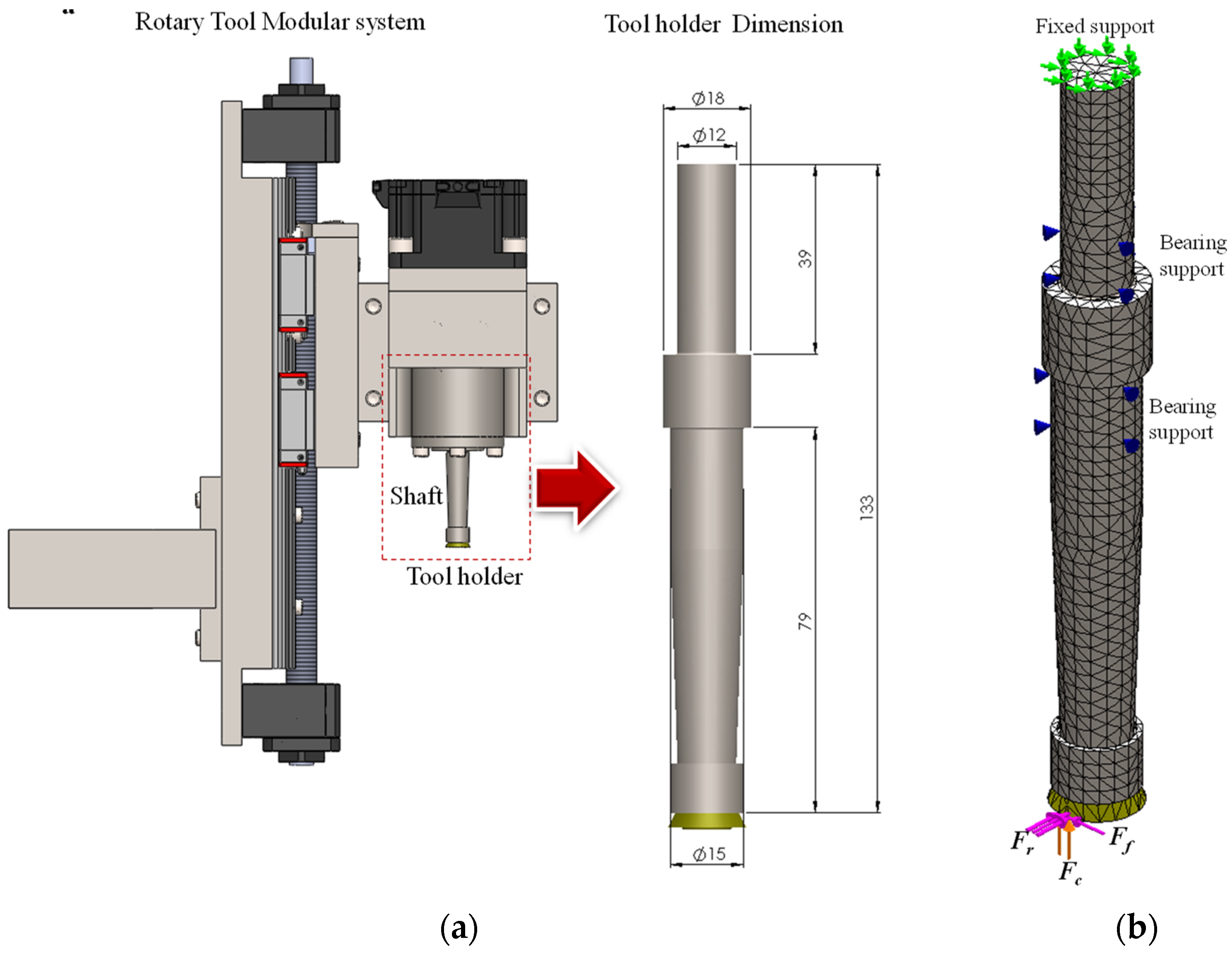
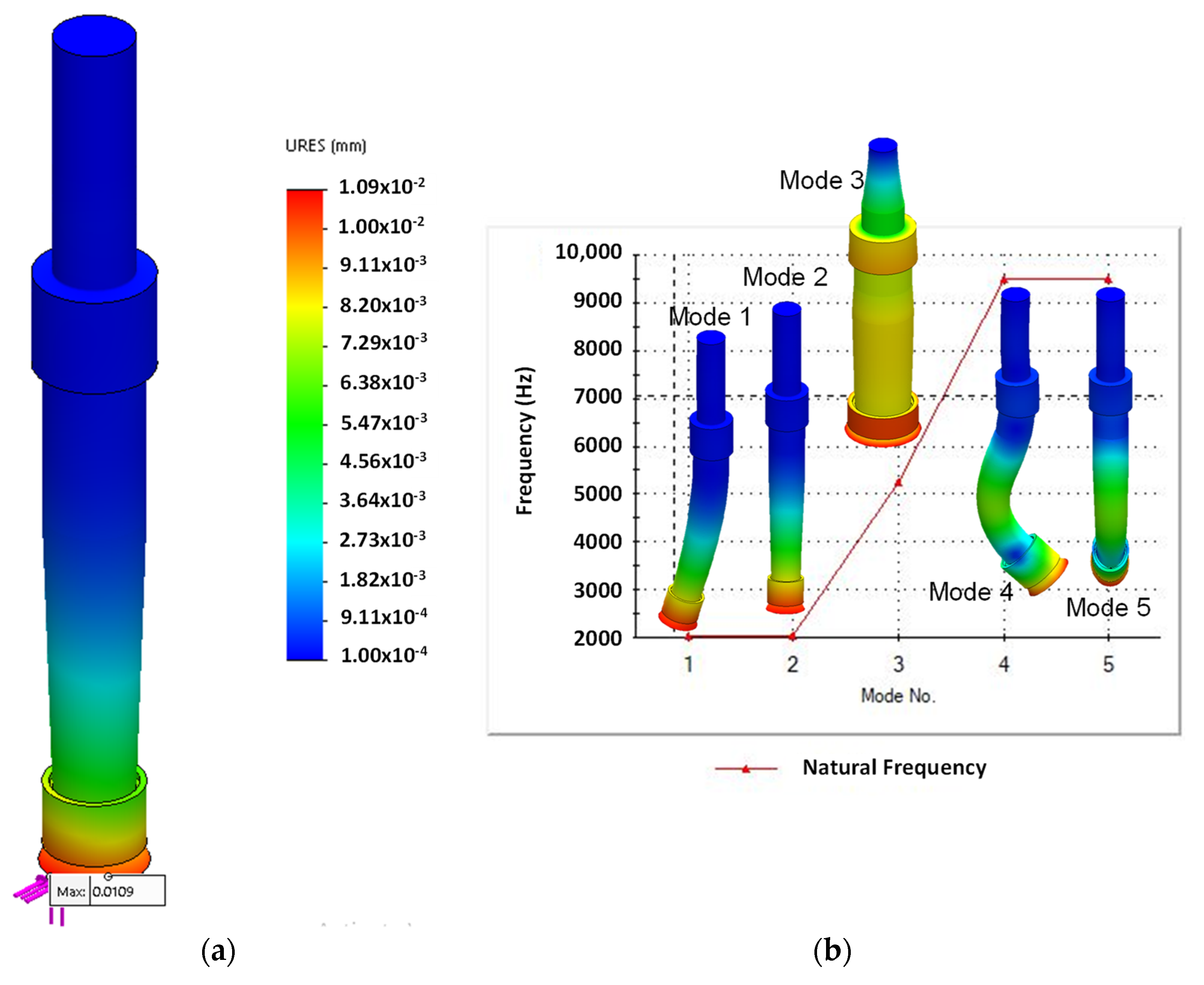
2. Rotary Tool Holder Structure

The rotary tool holder structure of the rotary tool system must have sufficient static and dynamic stiffness to withstand the forces that arise during the machining process. The stiffness of this structure directly influences the diametrical error and the roughness of the machined surfaces. For assessing the stiffness, the quantitative analysis of static and dynamic deformation of the rotary tool holder was carried out. Finite Element Analysis (FEA) was used to estimate the deflection, natural frequency, and mode shape (vibrating form) of the rotary tool holder. Figure 1 shows the FEA model of the rotary tool holder. The shape and dimensions of the rotary tool holder can be seen in Figure 1.a. The rotary tool holder shape is a shaft made of AISI 1045 steel, which has a modulus of elasticity of 205 Gpa and an ultimate strength of 625 Mpa. The boundary conditions for FEA simulation of deflection and natural frequency are defined as shown in Figure 1b. A shaft is supported by two bearings. In addition, the upper end of the shaft is held by a motor shaft, while the lower end is given load due to the cutting force. Figure 2 shows the cutting forces acting on the rotary tool, consisting of the main cutting force (Fc), feed force (Ff), and radial force (Fr). For determining the cutting forces, Finite Element Method (FEM) simulation of turning with the ADRT was applied, which has been previously carried out by the authors of [28]. In this FEM simulation, the workpiece material used was a titanium alloy, and the cutting conditions were chosen based on the experimental design. FEM simulation of turning with the ADRT results shows that the maximum values of Fc, Ff, and Fr are 314, 21, and 32 N, respectively (see Figure 2). Values of cutting forces were further inputted as the load forces that act on the tip of the rotary tool in the quantitative analysis of the stiffness of the rotary tool holder.
The results show that the maximum deflection of the rotary tool holder is 0.0109 mm (see Figure 3a), which is much smaller than the depth of cut used in this study, which is 0.2 mm. Furthermore, the minimum natural frequency of the mode shape of a rotary tool holder is 2050 Hz (see Figure 3b). To prevent the rotary tool holder from vibrating during the machining process, its natural frequency should not be equal to or close to the vibration frequency of the rotating parts of the machine tool. It has been known that the frequency of the tool rotation (fe, Hz) has a relation to the speed of the machine tool spindle (n, rpm) during the machining process, which can be calculated with the following equation [29]:
f e = n 60   Hz
With the spindle speed of the tool holder rotating at 2000 rpm, the frequency of the tool rotation can be determined to be 33.33 Hz. The value of tool rotation frequency is much smaller than the natural frequency of rotary tool holders. Therefore, based on the results obtained from quantitative analysis, it can be stated that the rotary tool holder has been designed with sufficient stiffness to be used in this study.

3. Materials and Methods

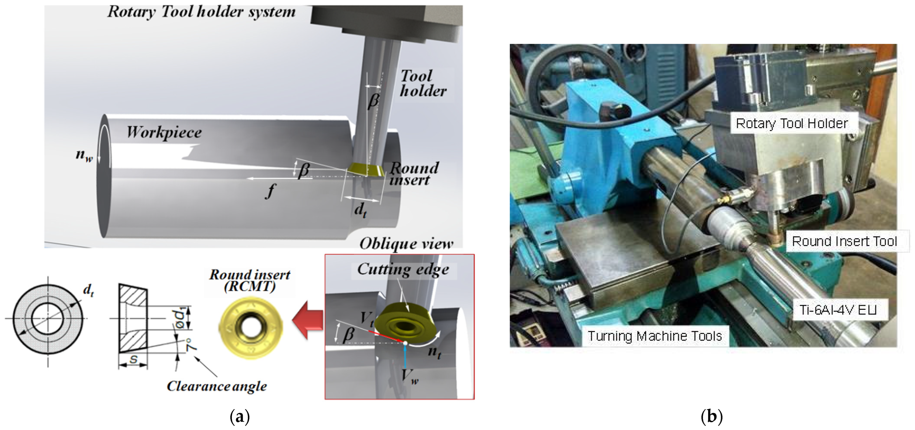
3.1. Experimental Procedure

The titanium alloy (Ti-6Al-4V ELI) from Titan Engineering tested in this study was Grade 23 of the ASTM standard. Table 1 shows the chemical composition and mechanical properties of Ti-6Al-4V ELI. The geometrical shape of the titanium alloy material tested was a solid cylindrical rod with a diameter of 50 mm.
The lathe machine tool has a motor with a power of 4 kW and a spindle with a maximum rotation of 2200 rpm, which were used during the turning test. For implementing the turning with the ADRT, a modular rotary tool holding system has been designed and fabricated (see Figure 4), which was mounted on the tool post of a turning machine tool. The rotary tool holder system was also equipped with a Brushless Vexta AXUM590-A DC Motor with a maximum rotational speed of 2000 rpm so that the tool can be turned actively in a wide enough speed range. The motor was also controlled by the regulator (AXUD90C) to set the desired motor speed.
The Round Tool Insert (RCMT-RX AC630M) from Sumitomo was mounted at the end of the modular turning tool spindle shaft used for machining Ti-6Al-4V ELI material. The tool insert material was carbide with three layers coated, consisting of α-Al2O3, TiCN, and cemented carbide. The round tool insert was used, which has dimensions and geometry of 16 and 20 mm in diameter (dt), a rake angle of 5 deg., and a clearance angle of 7 deg (see Figure 4a). The experimental setup for this study is shown in Figure 4b.
The surface roughness and morphology of Ti-6Al-4V ELI was investigated using dry machining, surface roughness measurement equipment, and microscopic scale observations. The portable surface roughness measurement equipment (Mitutoyo Surftest SJ 201) was used to measure the average surface roughness Ra. The machined surface roughness was measured three times with a measured length of 5 mm. To ensure the validity of the measurement data, the tool rotary insert was replaced with a new one for each machining condition. The Scanning Electron Microscope (SEM, Carl Zeiss Evo MA 10) was used for observing the microscopic scale of the surface morphology of Ti-6Al-4V ELI material.

3.2. Design of Experiment

One method that can be used for the efficient design of an experiment is the statistical approach using the Taguchi method, especially in the machining test of materials that are difficult to cut such as titanium and its alloys. This method was chosen because there are only a small amount of experimental data required but it can give the result that the level of the selected factor can be known as the level of influence on the response variable. The Taguchi method was utilized for analyzing the effects of cutting parameters of turning with the ADRT of Ti-6Al-4V ELI on the surface roughness. Five cutting parameters of turning with the ADRT were chosen as input for the design of experiments: cutting speed (Vw), tool revolution speed (nt), tool diameter (dt), inclination angle (β), and feed (f). An illustration of these input parameters can be seen in Figure 4a. The input parameters were tested for their effects on the response variable, that is, the average surface roughness. A detailed list of input parameters (factors) and their associated levels is presented in Table 2. Based on the selected input and level parameters, the design matrix of the experiment was formulated in the orthogonal array L36 (23 × 32) of Taguchi’s experimental design (see Table 3).

4. Results

4.1. Surface Roughness Analysis

The results of the average surface roughness (Ra) of the machined surface of the Ti-6Al-4V ELI material, which was machined using turning with the ADRT, are presented in Table 3. Two analyses were used for determining the influence level of input parameters and their interaction on the response variable, namely, the Signal-to-Noise (S/N) ratio and the Analysis of Variance (ANOVA). In the S/N ratio analysis, for obtaining the input parameters’ effects on the response variable, the performance characteristic of surface roughness is desired to be the smallest value of Ra. Therefore, the smaller the better has been chosen. It means that the higher the S/N ratio value, the lower the average surface roughness (Ra). The S/N ratio for smaller the better performance is calculated as follows:
η = 10 l o g 10 1 n i = 1 n y i 2
where the S/N ratio (η) is calculated from the observed values; yi, which represents the experimental observation value of several test data; and n is the number of replications of each test. The calculation results of the S/N ratio of the average surface roughness data are also presented in Table 3.
The response table of the S/N ratio to analyze the influence of input parameters on the average surface roughness was performed using the Taguchi method as presented in Table 4. This response table is also shown in the graphical form of the mean S/N ratio for each input parameter (see Figure 5). It is stated that the level of influence of input parameters in the response variable can be determined based on the delta value or the S/N ratio mean. The input parameter with the highest delta value is stated to have more effect on the response variable. It is clear from Table 4 and Figure 5 that the cutting speed (Vw) was the most influential parameter on the average surface roughness (rank 1). The characteristic of the average surface roughness value is the smaller the better. The higher S/N ratio of the cutting speed corresponds to the first level (Vw = 60 m/min, S/N = 4.686). In contrast to that, the S/N ratio with the smallest value (S/N = 0.144) was obtained for the second level of cutting speed (Vw = 210 m/min). It means that a small average surface roughness value was obtained at cutting speeds of 60 m/min compared with that obtained at a high cutting speed of 210 m/min. The influence level of other input parameters to the average surface roughness, that are tool inclination angle (β), tool revolution speed (nt), tool diameter (dt), and feed (f), were found to be ranked 2 (delta = 3.4550), ranked 3 (delta = 0.9948), ranked 4 (delta = 0.7672), and ranked 5 (delta = 0.5379), respectively.
However, the analysis of the S/N ratio is not able to determine the level of the significant effect of input parameters on the response variable. Therefore, for determining input parameters that have statistically significant effects on the machined surface roughness, the Analysis of Variance (ANOVA) method was used. In this method, the insignificant input parameters on the response variable are eliminated by the pooling process [30]. The pooling process is conducted using the step-wise regression of the ANOVA method [31]. In this study, the level of confidence was determined to be 95%. It means that the input parameter has p-values less than 0.05, which is considered a significant parameter influence on the response variable. The ANOVA test result for determining the influence of input parameters and their interaction on the average surface roughness is listed in Table 5.
Based on the ANOVA test results in Table 5, there are two parameters and their interactions that have a p-value of less than 0.05. These are cutting speed (Vw), the tool inclination angle (β), and the interaction between cutting speed and tool inclination angle (Vw * β), which have p-values of 0, 0.33, and 0.11, respectively. This result showed that the cutting speed, tool inclination angle, and their interactions have significant effects on the average surface roughness with an effect contribution of about 67%.
However, qualitative testing is needed to study in more detail the input parameters, which have a significant influence on the surface roughness. This testing was carried out by turning with the ADRT of Ti-6Al-4V ELI at a cutting speed ranging from 60 to 210 m/min, and also the tool inclination angles ranging from 5 to 15 deg. During turning with the ADRT, the average surface roughness values were measured at a time interval of one or two minutes. Moreover, the round cutting tools were used for about 20 min for each cut. The qualitative testing results will be discussed below.

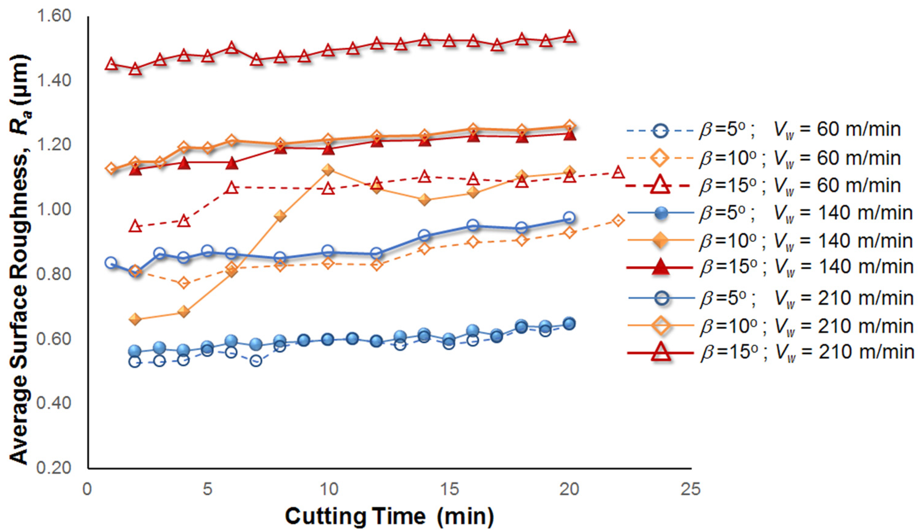
4.1.1. Effect of Cutting Speed

The measurement result of machined surface roughness during the turning with the ADRT of Ti-6Al-4V ELI at the different cutting speeds (60, 140, and 210 m/min) is shown in Figure 6. It is seen from this figure that average surface roughness was increased by increasing the cutting speed during the turning with the ADRT using a round tool diameter of 16 mm. In the case of a cutting speed of 60 m/min, the lowest average surface roughness of about 0.56 mm was obtained. With an increase in the cutting speed from 60 to 140 m/min, average surface roughness increased by about 0.72 mm. Finally, the highest average surface roughness obtained was about 1.47 mm when the cutting speed was increased to 210 m/min. The result with the same tendency was also obtained when the round tool diameter was changed to 20 mm, in which the average surface roughness value also increased with an increased cutting speed. The surface roughness obtained during turning with the ADRT of Ti-6Al-4V ELI was increased by approximately 50%, caused by the increase in cutting speed from 60 to 210 m/min. As seen in Figure 7, chips of Ti-6Al-4V ELI adhered to the cutting edge for all cutting speed levels during the turning with the ADRT. It is because the material property of titanium is chemically reactive with the cutting tools, including the types of carbide material. Consequently, the chips adhered to the cutting edge could generate the Built Up Edge (BUE) [32]. Thus, this causes the uneven and rough cutting edge of the round tool. This seems to cause an increase in the surface roughness along with increasing the cutting speed.

4.1.2. Effect of Tool Inclination Angle

Based on the qualitative testing, the surface roughness was increased by increasing the tool inclination angle (see Figure 8). It can be seen from this figure that the average surface roughness value obtained was about 0.58 mm at the tool inclination angle (β) of 5 deg., cutting speed (Vw) of 60 m/min, and round tool diameter (dt) of 16 mm. When the inclination angle was increased to 10 deg., the average surface roughness value obtained was higher than that obtained at the tool inclination angle of 5 deg., which is about 0.86 mm. An increase in the average surface roughness value was also obtained, which was about 1.06 mm when the angle of tool inclination was increased to 15 deg. Results with the same tendency were obtained when cutting speeds were changed to 140 and 210 m/min, in which average surface roughness was increased with increasing tool inclination angle. It is shown that the roughness of the machined surface obtained by turning with the ADRT of Ti-6Al-4V ELI was increased approximately 40% by increasing the tool inclination angles from 5 to 15 deg.
The surface roughness increases as the tool inclination angle is increased. This can be explained by the conceptual model of the relationship between the inclination angle of the tool and surface roughness during turning with the ADRT as illustrated in Figure 9. Based on that conceptual model, the surface roughness height (Rz) is determined by the geometric relationship between the length of cutting contact (lc) and the radius of a round tool (R) (see Figure 9a). It is assumed that the radius of a round tool is much larger than the feed, and then the length of cutting contact (lc) can be approached as a straight line so that an “oab” triangle is formed. Therefore, surface roughness height (Rz) can be determined by Equation (3), which is as follows:
R z = l c 2 l p 2
where lp is the length of the “ab” line. The length (lp) itself can be determined by the following equation:
l p = 2 R z R z 2
It is shown from Figure 9b that the length of cutting contact (lc) can also be determined based on the geometric relationship between the tool inclination angle and feed, which is formulated as the following equation:
l c = f 2 . C o s   β
where f is the feed and β is the tool inclination angle.
By substituting Equations (4) and (5) into Equation (3), the relationship between surface roughness height (Rz) and the inclination angle of the tool (β) can be determined by the following equation:
R z = f 2 8 R . C o s 2 β
where R is the radius of a round tool. Furthermore, the surface roughness height (Rz) can be converted into the surface roughness arithmetic value or average surface roughness (Ra) with the following equation:
R a = f 2 32 R . C o s 2 β
According to Equation (7), it is stated that the increase in the inclination angle of the tool can lead to the average surface roughness increasing during turning with the ADRT.

4.2. Surface Morphology of Ti-6Al-4V ELI

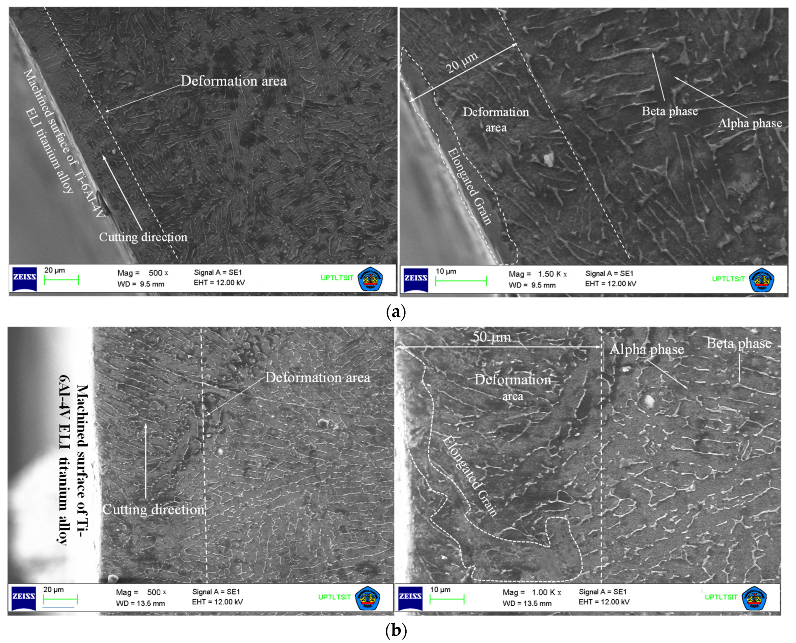
4.2.1. Damage Underneath the Machined Surface of Ti-6Al-4V ELI

The machining process creates an impact and impairs the top of or beneath the machined surfaces. This damage can occur as a result of heat generated during the machining process. The heat is caused by friction between the tool and workpiece and between the chip and workpiece during machining. Due to the material titanium’s poor conductivity, the heat generated is accumulated at the contact area between the edge of a cutting tool and the workpiece.
For investigating the damage beneath the machined surface of Ti-6Al-4V ELI, the cross-section of the machined surface material was observed using SEM with 500×–1500× magnification. Figure 10 shows a cross-section area of the machined surface deformation. The cutting speed contributes to the microstructure damage beneath the machined surface. As seen in Figure 10a, a cross-section of the workpiece material when turning with the ADRT of Ti-6Al-4V ELI at a cutting speed of 60 m/min is shown. There is a change in the microstructure orientation. A few millimeters beneath the top surface the change in orientation is greater.
The width of a deformed area can be seen in Figure 10. There is a difference in the microstructure orientation between the deformed and undeformed areas. The beta phase microstructure has an orientation perpendicular to the cutting speed direction in the undeformed area. Meanwhile, in the deformation area, which is the cutting area with a certain cutting speed, the orientation of the microstructure is linear to the cutting speed direction. Therefore, it can be stated that cutting speed affects the microstructure orientation during machining. A similar condition is shown in Figure 10b, where there is a change in microstructure orientation on the top and bottom surfaces of Ti-6Al-4V ELI after machining at 210 m/min.
Figure 10 also shows an area that experiences elongated grains along a machined surface. The thickness of this area is very thin, or just a few millimeters from the top surface (beneath the machined surface). The surface thickness experiences a change in microstructure of about 20 to 50 µm from the top surface when the cutting speed changes from 60 to 210 m/min. It showed that the changed microstructure area becomes larger when machining is undertaken at a higher cutting speed. After machining, the workpiece deformed plastically in the form of a changed orientation due to a combination of the tool’s compressive force [33] and the thermal load [34]. Although the deformation of plastic occurred a few micrometers beneath the top machined surface, interestingly, there was no damage on the machined surface, such as cracks and micro-pits, during turning with the ADRT. The damage on the machined surface of implant material (Ti-6Al-4V ELI) has to be avoided so that it has good biocompatibility. However, the average surface roughness value obtained in this study is still not classified as smooth for implant products, in which a smooth implant surface is required in the range of 0.00–0.4 μm of average surface roughness (Ra) [35].
Generally, in the high-speed machining process of titanium alloy, the machined surfaces have a defect on the top and a few microns beneath the machined surface. Evenly, their damage is in the form of the white layer or prevalent deformation. Previous researchers found a white layer on the top machined surface of Ti-6Al-4V ELI when turning using the non-rotational tool at a cutting speed of 95 m/min [36,37]. The white layer occurred because of the force and temperature simultaneously [36]. The high-speed machining generates high heat to transform titanium material into plastic deformation that can form the white layer on the top of the machined surface. The white layer has a high surface roughness level and also a high hardness value. As stated by Anurag, surface deformation with high surface hardness happens by overheating or work softening [38]. The work hardening of Ti-6Al-4V ELI can reduce the strength of the material so that it becomes very difficult to cut. Interestingly, after the turning with the ADRT of Ti-6Al-4V ELI at the highest cutting speed of 210 m/min, the white layer is absent on the top of the machined surface. It is possible because of the lower cutting temperature compared to machining using a non-rotational tool [20,39].

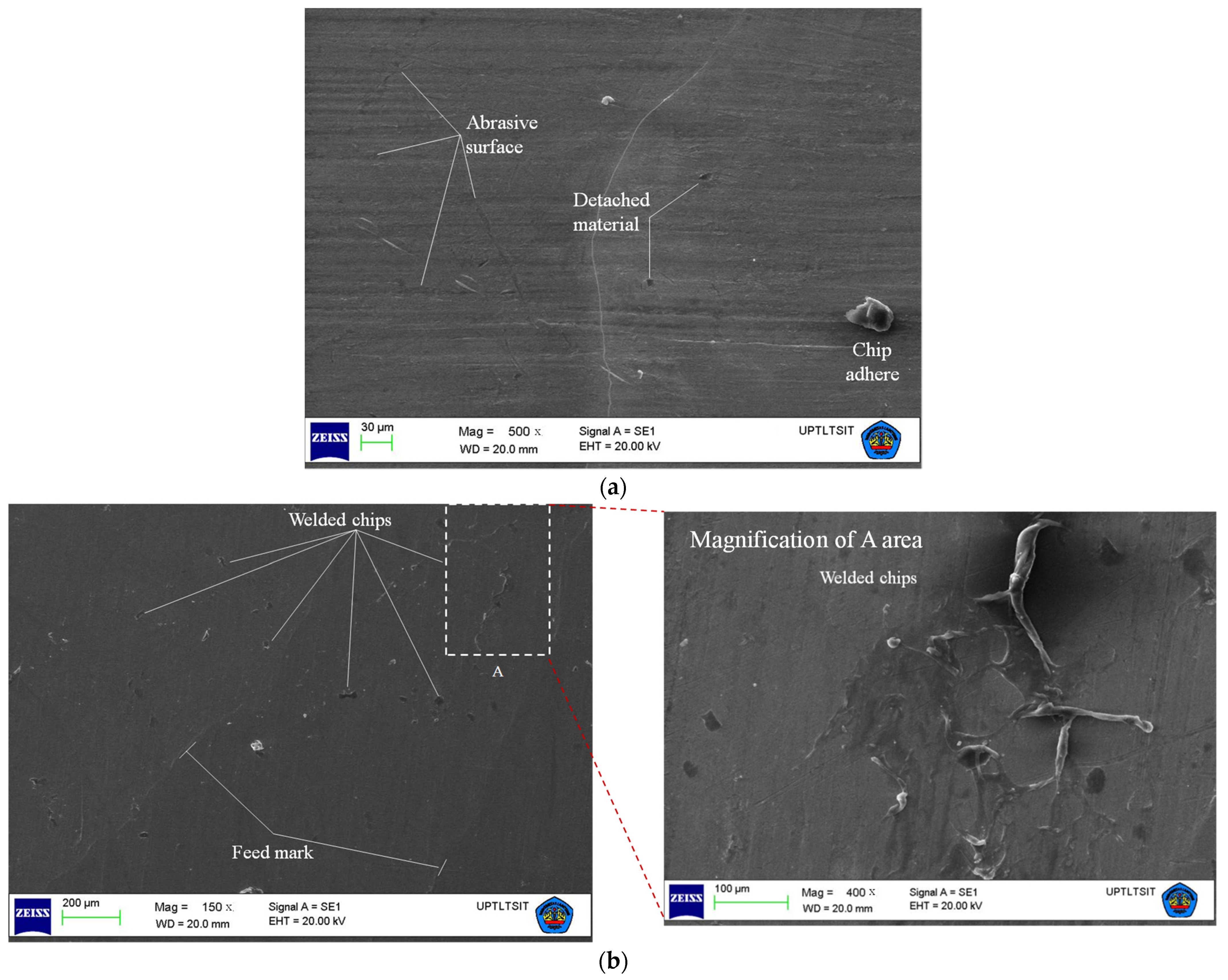
4.2.2. Machined Surface Damage of Ti-6Al-4V ELI

The correlation between the value of surface roughness and surface damage of titanium alloys during machining under certain conditions can be expressed in terms of the redeposited materials on the top surface, tool wear, and feed mark. The surface damage is commonly caused by the high cutting temperature [34,36]. Figure 11a depicts the morphology of the machined surface of Ti-6Al-4V ELI observed using SEM during turning with the ADRT at a cutting speed of 60 m/min. Some defects that appeared on the machined surfaces include the abrasive surface, detached material from the surface, and redeposited chips on the surface. The damage from surface abrasives is dominant, which is a result of scratching of the cutting tool. Some titanium material that comes off from the base material was also seen, but it was not much. This type damage occurred as a result of very strong bounded particles of the Ti-6Al-4V ELI material [40].
Other damage to the machined surface occurred when turning with the ADRT of Ti-6Al-4V ELI and was the welded chip on the machined surface, but it was only a small amount. It is possible that the machining process takes place regularly so that no chips are scattered on the machined surface. Another possibility is that there is not enough temperature generated to enable the chips to be welded on the machined surface. However, under certain machining conditions, the amount of welded chips on the machined surface is greater. It is achieved when machining takes place at a high generated temperature. Sometimes, the pressure of the cutting tool also causes some material to be welded to the machined surface [41]. However, the turning with the ADRT of Ti-6Al-4V ELI at a cutting speed of 60 m/min encountered surface abrasive damage, and some chips were welded to the surface, but only a little. Therefore, the average surface roughness value at low cutting speed tends to decrease.
Figure 11b shows the morphology of the machined surface of Ti-6Al-4V ELI during the turning process with the ADRT at a cutting speed of 210 m/min. The surface morphology observations were carried out using SEM with a magnification of 150×–400×. The dominant surface damage is the feed mark and welded chip on the surface. The feed mark is uniform along the machined surface, and it arose due to the feed rate factors. The direction of the feed mark is the same as the diagonal. It is possible due to the relative motion between tool speed and workpiece speed. A previous researcher also found the feed mark during machining of Ti-6Al-4V ELI using tools with coated cemented carbide [36]. It was stated that the feed mark is caused by plastic deformation and can increase the surface roughness.
The dominant surface damage that occurred is a welded chip. The chips were redeposited on the machined surface, as shown in Figure 11b. Welded chips on the machine surface were triggered by small and hot chips that tend to weld. The chips welded to the machined surface of Ti-6Al-4V ELI are spread evenly. They caused the machined surface to become rough or have a high average surface roughness value. The same case also occurred when titanium alloy is machined in dry conditions [32]. Many chips are welded to the workpiece surface, which is because of overheating in the chips. This is due to the machining taking place at a high cutting speed [42].

5. Conclusions

The present study focused on the investigation conducted on the surface roughness and morphology of Ti-6Al-4V ELI during turning with the ADRT. The turning with ADRT parameters consisting of the tool diameter, cutting speed, tool revolution speed, feed rate, and tool inclination angle were analyzed for their effects on the average surface roughness using the Taguchi method. Moreover, the surface morphology of this material during the turning with the ADRT was investigated using SEM. The main results are:
  • Based on the ANOVA analysis with a level of confidence of 95%, this indicates that the cutting speed, tool inclination angle, and their interaction are the most significant effects on the average surface roughness, with an effect contribution of about 67%, while the other parameters, such as the feed, tool diameter, and tool revolution speed, have no significant effects on the average surface roughness.
  • The average surface roughness was increased by approximately 50% due to the increase in the cutting speed from 60 to 210 m/min, whereas it was also increased by approximately 40% due to the increase in tool inclination angle from 5 to 15 deg.
  • Based on SEM observation, plastic deformation in the form of change in orientation and elongated grain has occurred beneath the Ti-6Al-4V ELI machined surface, in which the depth of deformation is thicker with increasing cutting speed. Nevertheless, no physical damage was observed, such as cracks, micro-pits, and a white layer on the machined surface morphology of Ti-6Al-4V ELI to indicate that the material surface has good biocompatible properties. However, the surface roughness obtained in this study is still not classified as smooth for implant products.
In conclusion, the surface roughness of Ti-6Al-4V ELI during turning with the ADRT was significantly influenced by the cutting speed and tool inclination angle. Chips of Ti-6Al-4V ELI have adhered to the tool edge, which may result in the uneven and rough edge of the round cutting tool. This can cause an increase in the average surface roughness due to the increase in cutting speed. Based on the investigation of the machined surface morphology of Ti-6Al-4V ELI at a higher cutting speed of 210 m/min, the surface defects such as the redeposited materials and feed marks were observed. This has also contributed to the largest average surface roughness value. In addition, the increase in tool inclination angle is followed by an increase in the contact length between the edge of a round tool and the machined surface. This can cause the average surface roughness to increase during the turning with the ADRT.

Author Contributions

Conceptualization, S.H. and Y.B.; methodology, S.H.; software, G.A.I.; validation, S.H., Y.B. and G.A.I.; formal analysis, Y.B.; investigation, S.H. and G.A.I.; resources, S.H.; data curation, S.H.; writing—original draft preparation, S.H.; writing—review and editing, S.H., Y.B. and G.A.I.; visualization, S.H.; supervision, Y.B.; project administration, S.H. All authors have read and agreed to the published version of the manuscript.

Funding

The authors gratefully acknowledges the University of Lampung’s graduate research grants, LPPM (Grant No.: 1256/UN26.21/PP/2018).

Data Availability Statement

Not applicable.

Conflicts of Interest

The authors declare no conflict of interest.

References

  1. Mai, P.T.; Bormann, T.; Sonntag, R.; Kretzer, J.P.; Gibmeier, J. Short-Term Heat Treatment of Ti6Al4V ELI as Implant Material. Materials 2020, 13, 4948. [Google Scholar] [CrossRef] [PubMed]
  2. Duraccio, D.; Mussano, F.; Faga, M.G. Biomaterials for dental implants: Current and future trends. J. Mater. Sci. 2015, 50, 4779–4812. [Google Scholar] [CrossRef]
  3. Bocchetta, P.; Chen, L.-Y.; Tardelli, J.D.C.; Reis, A.C.D.; Almeraya-Calderón, F.; Leo, P. Passive Layers and Corrosion Resistance of Biomedical Ti-6Al-4V and β-Ti Alloys. Coatings 2021, 11, 487. [Google Scholar] [CrossRef]
  4. Moghaddam, N.S.; Andani, M.T.; Amerinatanzi, A.; Haberland, C.; Hufi, S.; Miller, M.; Elahinia, M.; Dean, D. Metals for bone implants: Safety, design, and efficacy. Biomanuf. Rev. 2016, 1, 1. [Google Scholar] [CrossRef]
  5. Sakurai, K.; Nakatsukasa, R.; Hayashi, M.; Obikawa, T. Air jet assisted milling of titanium alloy Ti-6Al-4V ELI at high cutting speed. Key Eng. Mater. 2015, 656–657, 168–173. [Google Scholar] [CrossRef]
  6. Rahman, S.S.; Ashraf, M.Z.I.; Bashar, M.S.; Kamruzzaman, M.; Nurul Amin, A.K.M.; Hossain, M.H. Crystallinity, surface morphology, and chemical composition of the recast layer and rutile-TiO2 formation on Ti-6Al-4V ELI by wire-EDM to enhance biocompatibility. Int. J. Adv. Manuf. Technol. 2017, 93, 3285–3296. [Google Scholar] [CrossRef]
  7. Machado, A.R.; Wallbank, J. Machining of titanium and its alloys—A review. Proc. Insin. Mech. Eng. 1990, 204, 53–60. [Google Scholar] [CrossRef]
  8. Das, R.K.; Ngaihte, S.K.; Prasad, R.; Kakoti, A.; Hoque, R.; Sahu, S.K.; Badgayan, N. Experimental Investigation into electric discharge machining of Ti-6Al-4 V ELI alloy: An insight into biomedical applications. Mater. Today Proc. 2021, 46, 30–35. [Google Scholar] [CrossRef]
  9. Hedberg, G.K.; Shin, Y.C. Laser assisted milling of Ti-6A-4V ELI with the analysis of surface integrity and its economics. Lasers Manuf. Mater. Process. 2015, 2, 164–185. [Google Scholar] [CrossRef]
  10. Dandekar, C.R.; Shin, Y.C.; Barnes, J. Machinability improvement of titanium alloy (Ti-6Al-4V) via LAM and hybrid machining. Int. J. Mach. Tools Manuf. 2010, 50, 174–182. [Google Scholar] [CrossRef]
  11. Sisodiya, M.S.; Bajpai, V. An Insight: Machining of Titanium Alloys & Associated Tool Wear. IOP Conf. Ser. Mater. Sci. Eng. 2021, 1017, 012013. [Google Scholar] [CrossRef]
  12. Ibrahim, G.A.; Che Haron, C.H.; Ghani, J.A. Evaluation of PVD-inserts performance and surface integrity when turning Ti-6Al-4V ELI under dry machining. Adv. Mater. Res. 2011, 264–265, 1050–1055. [Google Scholar] [CrossRef]
  13. Nabhani, F. Machining of aerospace titanium alloys. Robot. Comput. Integr. Manuf. 2001, 17, 99–106. [Google Scholar] [CrossRef]
  14. Mori, M.; Furuta, M.; Nakai, T.; Fukaya, T.; Liu, J.; Yamazaki, K. High- speed machining of titanium by new PCD tools. SAE Trans. 1999, 108, 682–688. [Google Scholar] [CrossRef]
  15. Brinksmeier, E.; Riemer, O. Procurement of optical surfaces generated by diamond turning. Int. J. Mach. Tools Manuf. 1998, 38, 699–705. [Google Scholar] [CrossRef]
  16. Liu, W.; Liu, Z. High-pressure coolant effect on the surface integrity of machining titanium alloy Ti-6Al-4V: A review. Mater. Res. Express 2018, 5, 032001. [Google Scholar] [CrossRef]
  17. Muthukrishnan, N.; Davim, P. Influence of coolant in machinability of titanium alloys (Ti-6Al-4V). J. Surf. Eng. Mater. Adv. Technol. 2011, 1, 9–14. [Google Scholar] [CrossRef]
  18. Yasir, A.M.S.; Hassan, C.H.; Jaharah, A.G.; Nagi, H.E.; Yanuar, B.; Gusri, A. Machinalibilty of Ti-6Al4V under dry and near dry condition using carbide tools. Open Ind. Manuf. Eng. J. 2009, 2, 1–9. [Google Scholar] [CrossRef]
  19. Pimenov, D.Y.; Mia, M.; Gupta, M.K.; Machado, A.R.; Tomaz, Í.V.; Sarikaya, M.; Kapłonek, W. Improvement of machinability of Ti and its alloys using cooling-lubrication techniques: A review and future prospect. J. Mater. Res. Technol. 2021, 11, 719–753. [Google Scholar] [CrossRef]
  20. Harun, S.; Shibasaka, T.; Moriwaki, T. Cutting temperature measurement in turning with actively driven rotary tools. Key Eng. Mater. 2009, 389–390, 138–143. [Google Scholar] [CrossRef]
  21. Takahashi, W.; Sasahara, H.; Yamamoto, H.; Takagi, Y. FEM simulation on the effect of cutting parameters in the driven rotary cutting. Key Eng. Mater. 2015, 625, 564–569. [Google Scholar] [CrossRef]
  22. Karaguzel, U.; Olgun, U.; Uysal, E.; Slaves, E.; Bakkal, M. Increasing tool life in machining of difficult-to-cut materials using nonconventional turning processes. Int. J. Adv. Manuf. Technol. 2015, 77, 1993–2004. [Google Scholar] [CrossRef]
  23. Lei, S.; Liu, W. High-speed machining of titanium alloys using the driven rotary tool. Int. J. Mach. Tools Manuf. 2002, 42, 653–661. [Google Scholar] [CrossRef]
  24. Hosokawa, A.; Yoshimatsu, H.; Koyano, T.; Furumoto, T.; Hashimoto, Y. Turning of difficult-to-machine materials with an actively driven rotary tool (ADRT)—Proposition of reciprocating turning contingent on fundamental cutting characteristics. J. Adv. Mech. Des. Syst. Manuf. 2018, 12, 1–9. [Google Scholar] [CrossRef]
  25. Harun, S.; Shibasaka, T.; Moriwaki, T. Cutting Mechanics of Turning with Actively Driven Rotary Tool. J. Adv. Mech. Des. Syst. Manuf. 2008, 2, 579–586. [Google Scholar] [CrossRef]
  26. Nguyen, T.-T.; Duong, Q.-D.; Mia, M. Multi-response optimization of the actively driven rotary turning for energy efficiency, carbon emissions, and machining quality. Proc. Inst. Mech. Eng. Part B J. Eng. Manuf. 2021, 235, 2155–2173. [Google Scholar] [CrossRef]
  27. Joch, R.; Sajgalik, M.; Czan, A.; Holubjak, J.; Cedzo, M.; Cep, R. Effects of Process Cutting Parameters on the Ti-6Al-4V Turning with Monolithic Driven Rotary Tool. Materials 2022, 15, 5181. [Google Scholar] [CrossRef]
  28. Burhanuddin, Y.; Harun, S.; Ibrahim, G.A. FEM Simulation of Machining AISI 1045 Steel Using Driven Rotary Tool. Appl. Mech. Mater. 2015, 786, 77–82. [Google Scholar] [CrossRef]
  29. Rizal, M.; Ghani, J.A.; Nuawi, M.Z. Development and testing of an integrated rotating dynamometer on tool holder for milling process. Mech. Syst. Signal Process. 2015, 52–53, 559–576. [Google Scholar] [CrossRef]
  30. Kumar, S.; Satsangi, P.S.; Prajapati, D.R. Optimization of green sand casting process parameters of a foundry by using the Taguchi’s method. Int. J. Adv. Manuf. Technol. 2011, 55, 23–34. [Google Scholar] [CrossRef]
  31. Mohammadpour, S.; Yazdian, N.; Wang, H.P.; Carlson, B.; Kovacevik, R. Effect of filler wire composition on performance of Al/Galvanized steel joints by the twin spot laser welding-brazing method. J. Manuf. Processes. 2018, 31, 20–34. [Google Scholar] [CrossRef]
  32. Hosseini, A.; Kishawy, H.A. Cutting tool materials and tool wear. In Machining of Titanium Alloys; Materials Forming, Machining and Tribology; Davim, J., Ed.; Springer: Berlin/Heidelberg, Germany, 2014; pp. 31–56. [Google Scholar] [CrossRef]
  33. Burhanuddin, Y.; Che Haron, C.H.; Ghani, J.A.; Ariffin, A.K.; Ibrahim, G.A.; Yasir, A.; El-Maghribi, N.H. The effects of CBN cutting tool grades on the tool life and wear mechanism when dry turning of titanium alloy. Asian Int. J. Sci. Technol. Prod. Manuf. 2008, 1, 105–110. [Google Scholar]
  34. Safari, H.; Sharif, S.; Izman, S.; Jafari, H. Surface integrity characterization in high-speed dry end milling of Ti-6Al-4V titanium alloy. Int. J. Adv. Manuf. Technol. 2015, 78, 651–657. [Google Scholar] [CrossRef]
  35. Gehrke, P.; Dinkel, J.; Fischer, C.; Schmenger, K.; Sader, R. Surface Roughness and Necessity of Manual Refinishing Requirements of CAD/CAM-Manufactured Titanium and Cobalt-Chrome Bars—A Pilot Study. Open Dent. J. 2019, 13, 316–326. [Google Scholar] [CrossRef]
  36. Ibrahim, G.A.; Che Haron, C.H.; Ghani, J.A. Surface integrity of Ti-6Al-4V ELI when machined using coated carbide tools under dry cutting conditions. Int. J. Mech. Mater. Eng. (IJMME) 2009, 4, 191–196. [Google Scholar]
  37. Che Haron, C.H. Tool life and surface integrity in turning titanium alloy. J. Mater. Process. Technol. 2001, 118, 231–237. [Google Scholar] [CrossRef]
  38. Anurag, R.K.; Roy, S.; Joshi, K.K.; Sahoo, A.K.; Das, R.K. Machining of Ti-6Al-4V ELI alloy: A brief review. IOP Conf. Ser. Mater. Sci. Eng. 2018, 390, 012112. [Google Scholar] [CrossRef]
  39. Ueda, T. Turning with Rotary Tools. In The International Academy for Production Engineering; CIRP Encyclopedia of Production, Engineering; Laperrière, L., Reinhart, G., Eds.; Springer: Berlin/Heidelberg, Germany, 2014; pp. 1255–1261. [Google Scholar] [CrossRef]
  40. Ibrahim, G.A.; Arinal, H.; Zulhanif, Z.; Che Haron, C.H. Microstructure alterations of Ti-6Al-4V ELI during turning by using tungsten carbide inserts under dry cutting conditions. Int. J. Eng. Technol. Dev. 2013, 1, 37–40. [Google Scholar]
  41. Skazochkin, A.V.; Useinof, S.V.; Kislov, S.V. Sufrace hardening of titanium alloy by minerals. Lett. Mater. 2018, 8, 81–87. [Google Scholar] [CrossRef]
  42. Safari, H.; Sharif, S.; Izman, S.; Jafari, H.; Kurniawan, D. Cutting force and surface roughness characterization in cryogenic high-speed end milling of Ti-6Al-4V ELI. Mater. Manuf. Process. 2014, 29, 350–356. [Google Scholar] [CrossRef]
Figure 1. FEA model of the rotary tool holder: (a) rotary tool holder and its dimensions; (b) boundary condition for FEA simulation of deflection and natural frequency.
Jmmp 06 00105 g001
Figure 2. (a) FEM simulation of turning with the ADRT and (b) maximum cutting forces obtained (cutting conditions: cutting speed (Vw) 60 m/min, feed (f) 0.2 mm/rev, depth of cut (ap) 0.2 mm, tool revolution speed (nt) 2000 rpm, inclination angle (β) 0°, tool diameter (dt) 16 mm).
Jmmp 06 00105 g002
Figure 3. Static and dynamic deformation of the rotary tool holder: (a) deflection; (b) natural frequency.
Jmmp 06 00105 g003
Figure 4. (a) Modular rotary tool holder system and cutting parameters of turning with the ADRT; (b) experimental set-up.
Jmmp 06 00105 g004
Figure 5. The means of S/N ratio for each input parameter.
Jmmp 06 00105 g005
Figure 6. The effect of cutting speed on the average surface roughness (Ra).
Jmmp 06 00105 g006
Figure 7. The chips adhered on the cutting edge of a round tool.
Jmmp 06 00105 g007
Figure 8. Effects of the tool inclination angle on the average surface roughness (Ra).
Jmmp 06 00105 g008
Figure 9. Conceptual model of the relationship of tool inclination angles and surface roughness: (a) the geometrical relationship between cutting contact and round tool radius; (b) the relation between inclination angle of tool and feed.
Jmmp 06 00105 g009
Figure 10. Microstructure of Ti-6Al-4V ELI at the cross-section: (a) cutting speed of 60 m/min; (b) cutting speed of 210 m/min.
Jmmp 06 00105 g010
Figure 11. The surface damage of Ti-6Al-4V ELI when machined at cutting speed: (a) 60 m/min; (b) 210 m/min.
Jmmp 06 00105 g011
Table 1. Mechanical properties and chemical composition of Ti-6Al-4V ELI.
Contents (wt.%)Mechanical Properties
NCHFeOAlVTiUltimate Tensile Strength (Mpa)Yield Strength (Mpa)Elongation (%)
0.030.080.020.250.135.5–6.753.5–4.5Balance91082810
Table 2. Input cutting parameters (factors) of turning with the ADRT and their levels.
FactorsSymbolUnitLevels
123
Tool diameterdtmm1620-
Feedfmm/rev0.10.2-
Cutting speedVwm/min60210-
Tool revolution speedntrpm1007001500
Inclination angleβdeg51015
Table 3. Taguchi experimental design with orthogonal array L36 (23 × 32) and experimental results.
RunFactorsS/N RatioAverage Surface Roughness, Ra (μm)
dtfVwntβ
1160.16010052.050.79
2160.160700104.150.62
3160.1601500156.680.46
4160.16010052.050.79
5160.160700104.150.62
6160.1601500156.680.46
7160.121010056.320.48
8160.1210700102.050.79
9160.1210150015−4.381.66
10160.26010054.780.58
11160.260700103.350.68
12160.2601500153.270.69
13160.2210100101.110.88
14160.221070015−3.051.42
15160.2210150057.260.43
16160.2210100101.110.88
17160.221070015−3.051.42
18160.2210150057.260.43
19200.1210100100.031.00
20200.121070015−3.971.58
21200.121015005−4.441.67
22200.1210100100.031.00
23200.121070015−3.971.58
24200.121015005−4.441.67
25200.160100156.260.49
26200.16070058.400.38
27200.1601500102.620.74
28200.221010015−3.841.56
29200.221070053.700.65
30200.22101500100.950.90
31200.260100155.790.51
32200.26070056.320.48
33200.2601500102.580.74
34200.260100155.790.51
35200.26070056.320.48
36200.2601500102.580.74
Table 4. Response table for Signal-to-Noise Ratios of Ra for each input parameters.
LevelTool Diameter (dt)Feed (f)Cutting Speed (Vw)Tool Revolution Speed (nt)Inclination Angle (β)
12.79872.14614.68642.81094.2984
22.03152.68410.14382.61842.1035
3---1.81600.8434
Delta0.76720.53794.54260.99483.4550
Rank45132
Table 5. ANOVA test for average surface roughness (Ra).
SourceDegree of FreedomAdj. Sum of SquaresAdj. Mean SquareF-Valuep-ValueContribution
dt1353135310.630.4380.98%
Vw1123,810123,81022.190.000 *34.50%
β248,91424,4574.380.030 *13.63%
dt * Vw125,14725,1474.510.0507.01%
Vw * β268,20134,1016.110.011 *19.00%
Error1689,2915581 24.88%
Total23358,895 100.00%
R2 = 75.12%, Adj. R2 = 64.24%, Pred. R2 = 44.02%. * p < 0.05 significant parameter.
Publisher’s Note: MDPI stays neutral with regard to jurisdictional claims in published maps and institutional affiliations.

