Article

Punching of Ultra-High-Strength Spring Strips: Evolution of Cutting Edge Radius up to 1,000,000 Strokes for Three Punch Materials

Fraunhofer Institute for Machine Tools and Forming Technologies IWU, 09126 Chemnitz, Germany
*
Author to whom correspondence should be addressed.
J. Manuf. Mater. Process. 2022, 6(2), 38; https://doi.org/10.3390/jmmp6020038
Submission received: 28 February 2022 / Revised: 16 March 2022 / Accepted: 18 March 2022 / Published: 19 March 2022

Abstract

:
Punching of ultra-high-strength spring steel causes critical stresses in the tools. Pronounced wear and even spontaneous failure may occur. Wear of the punches influences the quality of the cutting surfaces of the blanked parts, which is predominantly determined by the cutting edge radius. The radius differs with an increasing number of strokes depending on the punch material. However, there are no studies characterizing the influence of the cutting edge radius on the cutting surface quality on an industrial scale, i.e., considering a very high number of strokes. In the presented study, punches made of high-speed steel, powder metallurgical steel and carbide were used to punch the ultra-high-strength steel 1.4310 (Rm = 1824 MPa) up to 1,000,000 strokes. The experiments were stopped at defined number of strokes, the punches were removed, nondestructively characterized regarding cutting edge radius and wear and reinstalled. It turned out that the radius differed significantly over the number of strokes and, further, varied depending on the punch material. Remarkably, the most low-cost material, precisely the high-speed steel, showed the smallest cutting edge radius of 16 µm and brought the parts with the best cutting surface quality (more than 30% burnish zone) after the maximum number of strokes. The results indicate clearly that the cutting edge radius develops differently for each regarded material and at different number of strokes. Therefore, it is of utmost importance to perform wear tests on different numbers of strokes under industrial conditions. With the knowledge gained, it will be possible to design optimized punches with lower costs and increased lifetime.

1. Introduction

The spring industry is faced with the challenging processing of ultra-high-strength strips, which exhibit strength ranging from 1500 to 2200 MPa [1]. Particularly with regard to the economical production of springs aiming at large quantities and highest possible number of strokes, it is essential to achieve an optimum between manufacturing costs and tool life of active parts such as punches. Punching is generally considered an economical cutting process that enables high productivity. Cutting itself is caused by large plastic deformation in the shear zone of the material [2]. The forming behavior is significantly influenced by the specific material behavior of the workpiece and by technological factors related to the tools (e.g., clearance) and machines (e.g., velocity) [3]. The impact velocity during conventional punching processes is approx. v = 0.5 m/s, which is in the range of high-speed blanking [4]. Due to high velocity and major forces occurring during punching, the high basic strength and hardness of sheet material led to a pronounced wear of the active parts and even to abrupt failure, particularly in case of spring-hard strips.
The most common types of wear are determined by adhesion, abrasion and disruptions of the surface [5]. These types of wear are influenced by various process parameters. Pereira et al. [6], for example, were able to show that production-related deviations on the surface of punches of only 15 µm can lead to greatly increased contact forces in the process and to spontaneous failure. Shirzadian et al. [7] investigated the influence of lubricants and dry cutting on galling in the process. The results show that dry punching led to higher galling resulting in higher friction forces at the interface of the punches. Furthermore, Zeidi et al. [8] shows that an insufficient heat treatment and a nonoptimized clearance can lead to tool premature damage. Therefore, a suitable head punch design, an optimized clearance and a new punch guiding solution are important to reduce the tool wear. The work of Otroshi et al. [9] also shows the importance of the punch geometry and the clearance of the common wear mechanisms. However, depending on the respective wear of the punch, the resulting quality of the cutting surface of the punched parts changes. With increasing cutting edge radius due to an increasing number of strokes, the burnish zone decreases and the fracture surface part of the cutting surface increases [5,10]. This implies a poorer quality of cutting surface and the finished part. Therefore, the cutting edge radius is the most important parameter of the punch with regard to the quality of the part and the tool life [11,12]. A radius that is very small can result in chipping and failure of the punch. Therefore, wear of punches needs to be minimized in a cutting process. One option to realize this is to use a different material for the punch dependent on the existing load profile. In practice, high-speed steels are used for softer strip materials or low loads [13]. As ultra-high-strength materials, tools made of powder metallurgical steels [14] or carbide [15] are used. To further increase tool life, various pretreatments, such as blasting [16] or shot peening [17], are applied to induce residual compressive stresses in the surface. These compressive stresses counteract occurring microcracks and therefore delay failure of the punches [18]. Likewise, coatings can positively influence the tribological system during punching and thus increase tool life. Various coating systems are commonly used, such as physical vapor-deposited (PVD) TiAlN [19], AlCrN [20] and chemical vapor-deposited (CVD) coatings [21,22]. Recent work by Bensely et al. [23] and Das et al. [24,25] show that wear can also be significantly reduced by a deep cryogenic (DCT) heat treatment at temperatures < −150 °C of tools. This DCT procedure reduces residual stresses and retained austenite by a substantial amount and allows for an easier precipitation of nanocarbides in the following temper steps, in general [26]. However, such special heat treatments and applied coatings significantly increase manufacturing costs.
In summary, wear directly on the cutting edge of the punch is essential for the life of the punch and the part quality. Most wear tests are conducted on a laboratory scale at very low stroke rates [27] and therefore the results are transferable to industrial applications only to a limited extent. There is still a lack of systematic studies investigating the evolution of the cutting edge radius of different punch materials and the resulting cutting surface quality by punching at very high stroke rates of ultra-high-strength strip steels. Therefore, the presented study focuses on identifying the influence of different punch materials on the respective type of wear, the cutting edge radius and the resulting cutting surface quality as a function of the number of strokes. For the first time, performance of different punch materials and the effect on the cutting edge radius is investigated on an industrial scale during punching. The knowledge gained regarding the correlations between punch material, wear, cutting edge radius and cutting surface quality is of high importance for further optimization (heat treatment, coating etc.) of punch materials in industrial use.

2. Materials and Methods
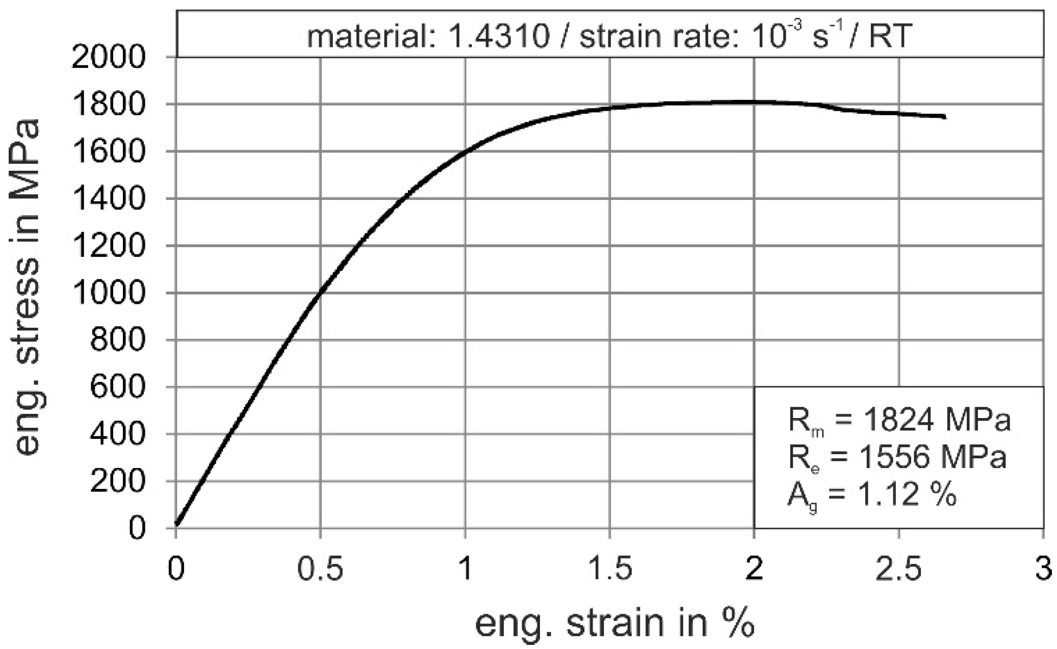
2.1. Materials

The presented study compares the punching performance and the evolution of the cutting edge radius for three different punch materials (commonly used in spring manufacturing) considering the punching of an ultra-high-strength strip material for 1,000,000 strokes. The following materials were used for manufacturing of the punches:
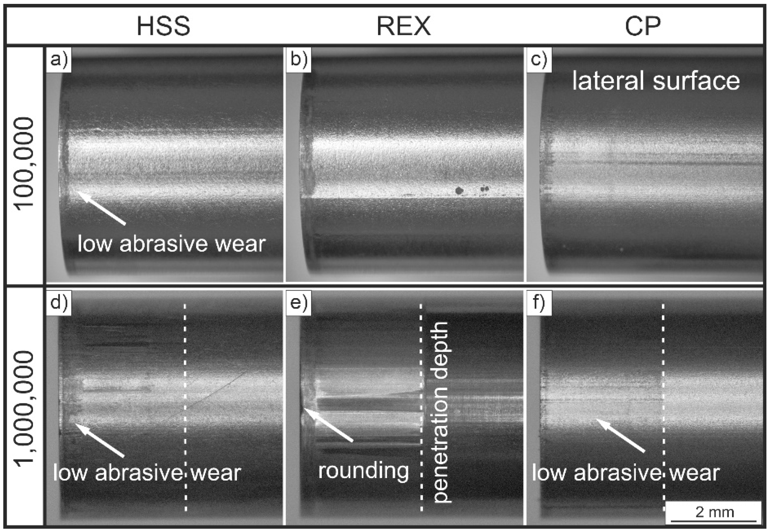
  • a low-cost high-speed alloy steel 1.3343 (X82WMoV6-5; hardness 64 HRC), abbreviated as HSS;
  • a powder metallurgical metal CPM Rex 76 (hardness 65 HRC), abbreviated as REX;
  • a carbide punch (ISO-Code G40, hardness 85 HRA), abbreviated as CP.
A cold-rolled, ultra-high-strength strip of metastable austenitic stainless-steel grade 1.4310 (X10CrNi18-8) with a sheet metal thickness t of 0.32 ± 0.01 mm and a width w of 35 mm was chosen for the experiments [28]. The stress-strain behavior of the strip material was characterized in a UPM 1475 Zwick/Roell universal testing machine (ZwickRoell GmbH) at room temperature with an initial strain rate of 10−3 s−1. The data were necessary for the numerical simulation and the used mean value curve is shown in Figure 1. The maximum tensile strength was 1824 ± 11 MPa, the yield strength 1556 ± 14 and the uniform elongation reached 1.12 ± 0.14%. Table 1 additionally shows the chemical compositions of the strip material and the three punch materials.

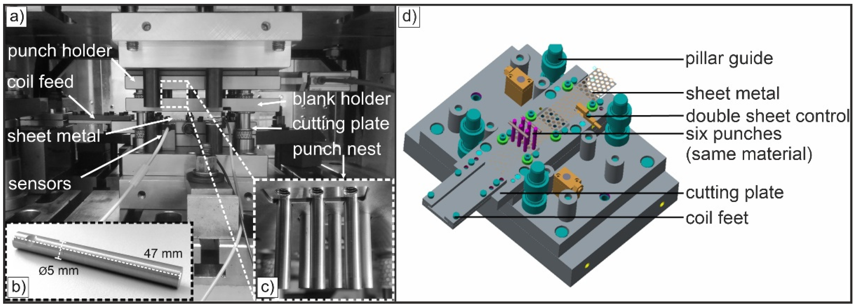
2.2. Punching Experiments up to 1,000,000 Strokes

The punches used for punching had a cylindrical geometry and a defined diameter D of 5 mm (Figure 2b). Manufacturing of all punches was conducted using the following process:
  • First, the raw geometry of punches was wire eroded.
  • Afterwards, a two-step shot blasting was performed to induce residual compressive stresses into the surfaces of the punches. The first shot blasting used silicon carbide and aluminum oxide, the second one used ceramic beads.
  • Finally, the front surfaces of all punches were ground and subsequently the cutting edges were polished.
Figure 2. Setup used for punching tests. Progressive die in BRUDERER BSTA 25USL high performance press (a), geometry of used punches with a diameter of 5 mm (b) and so-called punch nest with six punches (c). CAD image of the used tool for a detailed view (d).
Jmmp 06 00038 g002
Punching experiments were implemented in a high-performance press BRUDERER BSTA 25USL (BRUDERER AG), a mechanical press with an eccentric drive and a nominal punching force of F = 250 kN. The experimentation was conducted in a progressive die designed and manufactured for punching under industry-like conditions (Figure 2a,d). This requires a highly precise guiding accuracy that is achieved by utilizing a suitable pillar guide. The periphery of this punching press consists of a decoiler, a mechanical roller feed BBV 190/85 with oscillatory rollers and different sensors for process monitoring (punching forces, penetration depth, double sheet control). Punching experiments are performed up to 1,000,000 strokes and 250 strokes/min. Six punches, each made of the same material, were installed in the die at the same time (Figure 2c,d). The examinations were performed for the six punches. Since all punches of a material showed the same wear effects, the results are presented on the basis of one representative punch per material. The clearance was 15 µm, which corresponds to a relative clearance of 5% (clearance related to sheet thickness). The penetration depth was 3 mm and no lubricants were used during the punching.

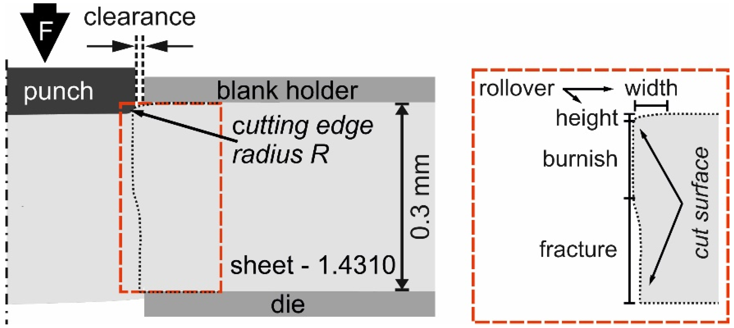
2.3. Measuring Concept
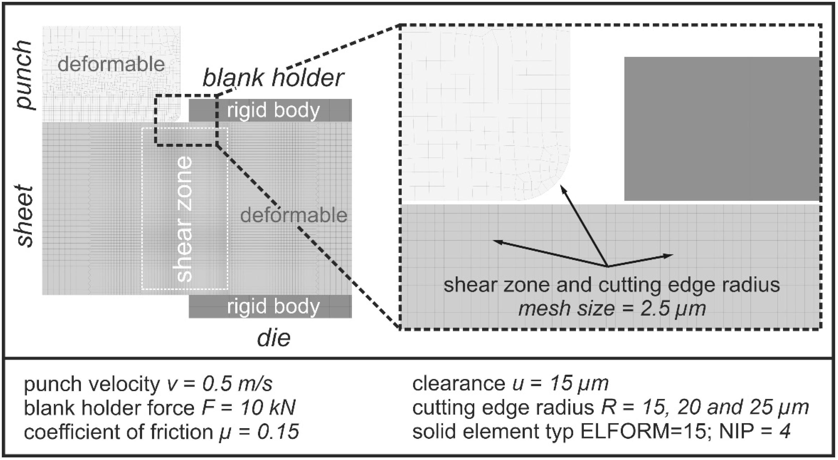
Punching was interrupted after 20,000, 50,000, 100,000 and 1,000,000 strokes. At those times, the punches were dissembled to enable a nondestructive examination of their wear status. A light-optical microscope SZX10 (Olympus) was used to examine wear both on lateral and front surfaces of all punches. Additionally, measurement of cutting surfaces of blanked parts was performed using the named microscope in order to analyze the rollover (width and height), burnish and fracture (Figure 3, red marking). Measuring of cutting edge of punches was realized using a CCD-camera 3D-MicroCAD (LMI Technology Systems). It combines an area-measured optical triangulation with a real-time interferometry and therefore allows for highly accurate measurement data of cutting edges and lateral surfaces. For this purpose, 400 parallel and equidistant lines are projected on the punch surface and analyzed afterwards. In general, an increase of the cutting edge radius R indicates an advancing abrasive wear of the cutting edge. After a nondestructive characterization of wear and quality of cutting surfaces, the punches were reinstalled in the die and the punching test series was continued until the next defined number of strokes. This methodology enables evaluating the evolution of the cutting edge radius, the wear of the punches and the cutting surface quality up to a total of 1,000,000 strokes.

2.4. FE-Simulation

The cutting edge radius R of punches is subject to heavy wear during punching. Radius changes permanently with increasing number of strokes and therefore significantly influences topography of cut surface and quality of the blanked parts. Consequently, it is of high importance how different radii affect quality of the cut surface.
To investigate the influence of different cutting edge radii on the local stresses in the punch (higher stresses are an indication of higher wear) and the resulting burnish zone of the cutting surface (indication for part quality), finite element simulations were performed using the explicit solver of LS-DYNA (DYNAmore GmbH). The 2D axisymmetric model illustrated in Figure 4 was used. The blank holder and die were modelled as rigid bodies, while the punch (D = 5 mm) and sheet (t = 0.3 mm) were considered to be deformable. The punch velocity was set as 0.5 m/s, the blank holder force and the coefficient of friction were set to 10 kN and µ = 0.15, respectively. The clearance was set to 15 µm and the cutting edge radius of the punch was varied from 15 to 25 µm. The finest mesh size was 2.5 µm (element size) in the cutting edge radius and also 2.5 µm in the shear zone of sheet metal. Axial symmetric solid elements typ ELFORM = 15 (element formulation options) with a NIP = 4 (number of integrations point) were used. Damage in the shear zone was calculated using the Johnson –Cook model (Equation (1)). The required material constants A, B, C, n and k were taken from the determined and extrapolated stress-strain curves of the sheet material 1.4310 (cf. Figure 1) and are listed in Table 2. The extrapolation of the stress-strain behavior for higher strain-rates (up to 102 s−1) were based on an existing material data map at Fraunhofer IWU for the steel 1.4404 (AISI 316L). Of course, this does not represent the real stress-strain behavior of the material 1.4310, but it is a good approximation for a first investigation of the influence of different cutting edge radii. However, the resulting burnish height in cutting surface (Figure 3, red marking) and local stress in punches were investigated for three exemplary cutting edge radii (15 µm, 20 µm and 25 µm).
σ ¯ = [ A + B ε ¯ n ] ( 1 + C l n ( ε ¯ ˙ ε ¯ ˙ 0 ) ) ( 1 ( T T r o o m T m e l t T r o o m ) k )

3. Results and Discussion

Figure 5 shows optical micrographs of blanked part surfaces after 1,000,000 strokes for the three investigated punch materials. Rollover width, rollover height, burnish height and fracture height were evaluated. The largest rollover (93 µm width and 28 µm height; Figure 5a) is observed for parts blanked with HSS punch. The lowest rollover (72 µm width and 21 µm height, Figure 5c) is measured for parts blanked with carbide punches. Remarkably, parts blanked with inexpensive HSS show the largest burnish zone of 129 µm. An increasing amount of burnish results in a better quality of the cut surface. Prior to these tests, it was expected that the much more costly REX and carbide punch materials would provide best performance at high stroke numbers and a good cut surface quality, due to their higher hardness (CP) and toughness (REX), but actually they exhibited poorer cutting surface qualities with a high amount of fracture area. Parts punched with REX had the smallest burnish zone with only 89 µm (Figure 5b). Consequently, these parts also had the largest fracture area of 180 µm.
Figure 6 shows representative stereomicroscopic images of lateral surfaces for the various punch materials at 100,000 and 1,000,000 strokes. Based on these images, occurring wear can be estimated in the first iteration. Up to 100,000 strokes, almost no signs of wear were detected for the investigated punch materials. Only slight abrasive wear phenomena appear directly at the cutting edge in all three materials (Figure 6a–c, white arrow). These are caused by tensile stresses occurring when the punching grid is stripped. In this process step, a small amount of material is either removed from the lateral surface of the punch or material removed from the strip is added to the punch [15]. In case of HSS and REX punches, slightly rounded cutting edges are observed as well. Chipping was not detected on any of the regarded punches.
After punching 1,000,000 parts, differences between the punch materials become more obvious. HSS still showed only marginal signs of wear (Figure 6d). Specifically, the lateral surface showed slight marks over the penetration depth of the punch into the punching grid (3 mm), but no chipping of the cutting edge occurred. REX, on the other hand, exhibited significantly stronger signs of wear in the area of lateral surface that dipped into punching grid (Figure 6e, dotted line). Similarly, clear local rounding of cutting edge become visible (white arrow, Figure 6e). Similar to HSS punches, carbide punches also showed relatively low wear on the lateral surface (Figure 6f, white arrow). Nevertheless, a slightly fractured surface with small cracks in cobalt matrix is present.
In addition to the optical microscopic investigations, the cutting edge radius of the investigated punches was determined at varying numbers of strokes. Measurements were done after 20,000, 50,000, 100,000 and 1,000,000 strokes. Important results of these measurements are shown in Figure 7. The REX punches showed the expected behavior. This means that from 50,000 strokes, the cutting edge radius increases steadily to 42 µm due to continuous wear and therefore is significantly higher than the initial value of 17 µm. These punches had the largest radius of the cutting edge of the three materials examined. The carbide punches showed a specific behavior up to 100,000 strokes, which was already described in more detail by Winter et al. in [15]. Precisely, a reduction in the cutting edge radius was observed, which was attributed to local chipping of the cobalt matrix and an associated local sharpening effect due to exposed tungsten carbide. At higher stroke numbers up to 1,000,000, this effect is no longer dominant and a clearly measurable rounding of cutting edge occurs. After 1,000,000 strokes, the cutting edge radius averages 24 µm and therefore is only slightly above the initial value of 19.5 µm. The HSS punches showed the most interesting behavior. Up to 100,000 strokes, the cutting edge radius increases almost equivalently to that of the REX punches. However, the radius subsequently decreases to the initial value of 16 µm. Consequently, a resharpening of the punches must have occurred in the cutting process.
A potential reason for this resharpening of the HSS punches is illustrated in Figure 8, which shows stereomicroscopic images of the cutting edges of the three investigated materials after 100,000 and 1,000,000 strokes. At 100,000 strokes, HSS and REX punches feature a slight rounding of the cutting edge that occurs as bright reflective areas (Figure 8a,b, white arrows). In case of carbide punches, slight disruptions are visible directly at the cutting edge, which lead to the aforementioned sharpening effect at 100,000 strokes (Figure 8c, dotted line) [15].
At 1,000,000 strokes, significant wear can be recognized on the face and on the lateral surfaces of the HSS punches directly adjacent to the cutting edge. Significant material removal occurred (Figure 8d, white arrows), but the cutting edge itself did not show any cracks. Light reflection of the cutting edge is not very pronounced and indicates only slight rounding (see Figure 6). Conversely, the REX punches showed a very large light reflection and consequently a larger rounding of the cutting edge (Figure 8e, white arrows). Material removal next to the cutting edge was observed, but it was significantly less pronounced when compared to HSS. The carbide punches showed a much more pronounced distortion of the cutting edge compared to their status after 100,000 strokes. Slight local material chipping was also visible (Figure 8f, dotted line).
Figure 9 shows the contour measurements of the face and the lateral surface and the resulting cutting edge radius (cf. Figure 8) for punches made of HSS, REX and CP. Considering the measurement of the front and the lateral surfaces in direct proximity of the cutting edge, a large amount of material was removed from the HSS punches (Figure 9a). In each case, a red dotted line represents a reference contour of an ideal punch. The marked circle with the radius R indicates the resulting cutting edge radius for the respective punch material (cf. Figure 8). On the lateral surface, the material loss amounts to 8 µm (maximum depth) × 50 µm (length) × 15,708 µm (punch circumference), i.e., 6,283,200 µm3 for the HSS punch. On the face surface, the material loss is lower. Here, a maximum depth of 9 µm and a length of approx. 30 µm corresponding to a material loss of 4,241,160 µm3 occur. Due to this material loss, the resulting effective cutting edge radius is reduced to 16 µm after 100,000 strokes (cf. Figure 8) and leads to the observed very good cutting surface results with a high percentage of burnish. Nevertheless, this increased material removal directly next to the cutting edge weakens the edge and can cause spontaneous failure of the HSS punch at higher numbers of strokes. In contrast, the punches made of REX (Figure 9b) and those made of CP (Figure 9c) showed homogeneous wear of the front and the lateral surfaces during punching. After a high number of strokes, for the REX punches the resulted wear in the observed increased cutting edge radius of R = 42 µm (cf. Figure 7). The CP punches shows a very accurate contour of the lateral and the front surface. The resulting cutting edge radius was R = 24 µm (cf. Figure 7). As shown in Figure 8b,c, the cutting edge is significantly more stable for these materials and, presumably, a significantly higher number of strokes might be achieved without failure of the punches.
Figure 10 summarizes the results of the numerical simulation considering the influence of different cutting edge radii on the local stresses in the punch and on the burnish fraction. It is evident that the stresses in the punch decrease with an increasing radius of the cutting edge. In case of the smallest radius of 15 µm the maximum stress of 1800 MPa occurs directly beside radius and at the cutting edge (Figure 10, arrows). This high local stress can cause material to wear preferentially in this area, as observed for the HSS punches (Figure 9a). If the radius increases, the maximum stress in the punch is significantly lower (20 µm and 25 µm radii show maximum stresses about 1600 MPa) and the stress distribution changes. The maximum stress is now within radius, not directly at the cutting edge and the strong localization next to the radius disappeared (Figure 10b,c). This results in a significantly more stable cutting edge. A further effect demonstrated in this study is that a decreasing cutting edge radius leads to an increased amount of burnish zone. The punch with the smallest radius of 15 µm exhibits a burnish height of approx. 125 µm. This is in very good agreement with the resulting cutting edge radius for HSS of 16 µm and a real burnish height of 129 µm (cf. Figure 5a). If the radius increases to 25 µm, the burnish height decreases continuously to 99 µm. In summary, it can be concluded that, despite the simplifications made, the performed simulation is suitable for accurately reproducing the influence of the material removal and the corresponding changes of the cutting edge radius on the cutting surface of the part and specifically on the burnish zone. If the cutting edge radius is increased, the stress directly at and next to the cutting edge decreases significantly. Therefore, tension does not localize on punch surface. Obviously, this behavior is material dependent and could only be observed for HSS punches in the present study. Due to their higher strength, powder metallurgical REX and CP are significantly more resistant against material removal.

4. Summary and Conclusions

Punching experiments were carried out up to 1,000,000 strokes with three different punch materials (a low-cost high-speed alloy steel 1.3343 (X82WMoV6-5), a powder metallurgical metal CPM Rex 76 and a carbide). The tests were stopped after defined numbers of strokes and the punches were examined regarding wear using nondestructive and optical methods. It was observed that all punches produced good cutting surfaces and that wear of the punches was low. As expected, REX and CP showed an increase of the cutting edge radius between 100,000 strokes and 1,000,000 strokes. However, the cheapest punches made of HSS showed a significant reduction of the cutting edge radius during this part of the test series. Contour measurements of the face and the lateral surfaces showed significant material removal directly beside cutting edge radius for this punch type. This resulted in a reduction of the effective cutting edge radius. Numerical FE simulations showed that for smaller cutting edge radii the stresses occurring in the punch are higher and localize directly beside the radius. Small radii lead to the best observed cutting result and a high amount of burnish zone (more than 30% and 129 µm, respectively). However, high material removal in direct proximity of the cutting edge leads to a weakening of the geometry. Consequently, it is assumed that higher numbers of strokes will cause spontaneous failure of the HSS punch. Therefore, the following key results can be obtained:
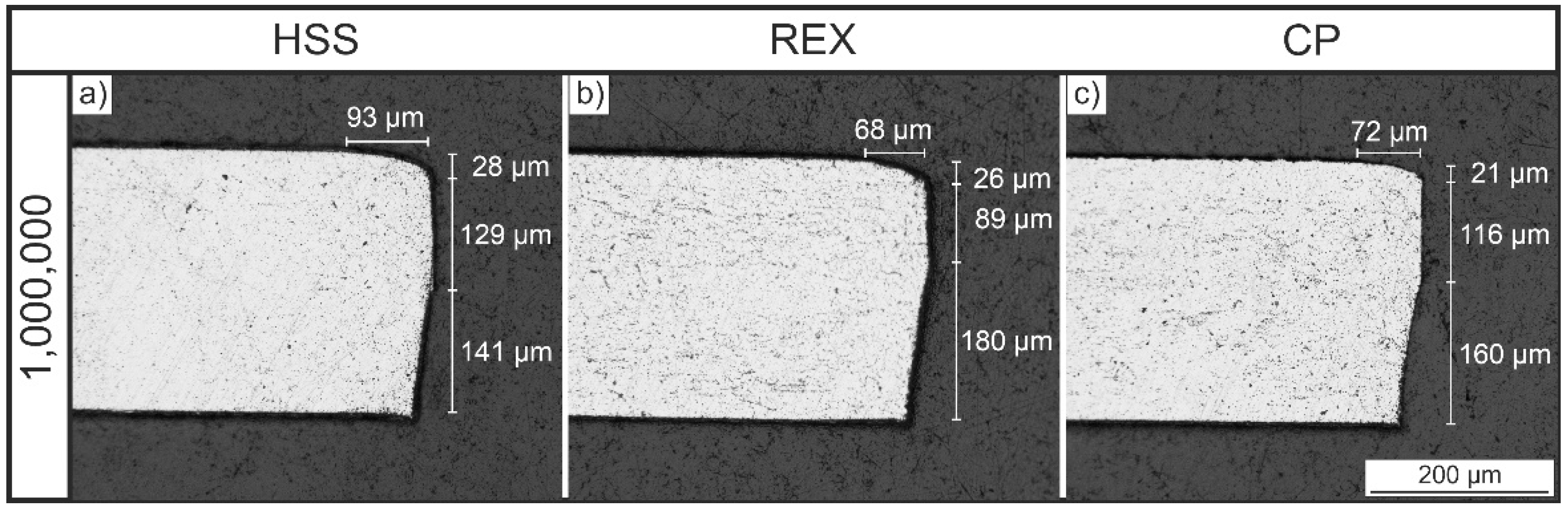
  • Punches made of HSS, REX and CP provided very good punching results even after 1,000,000 strokes.
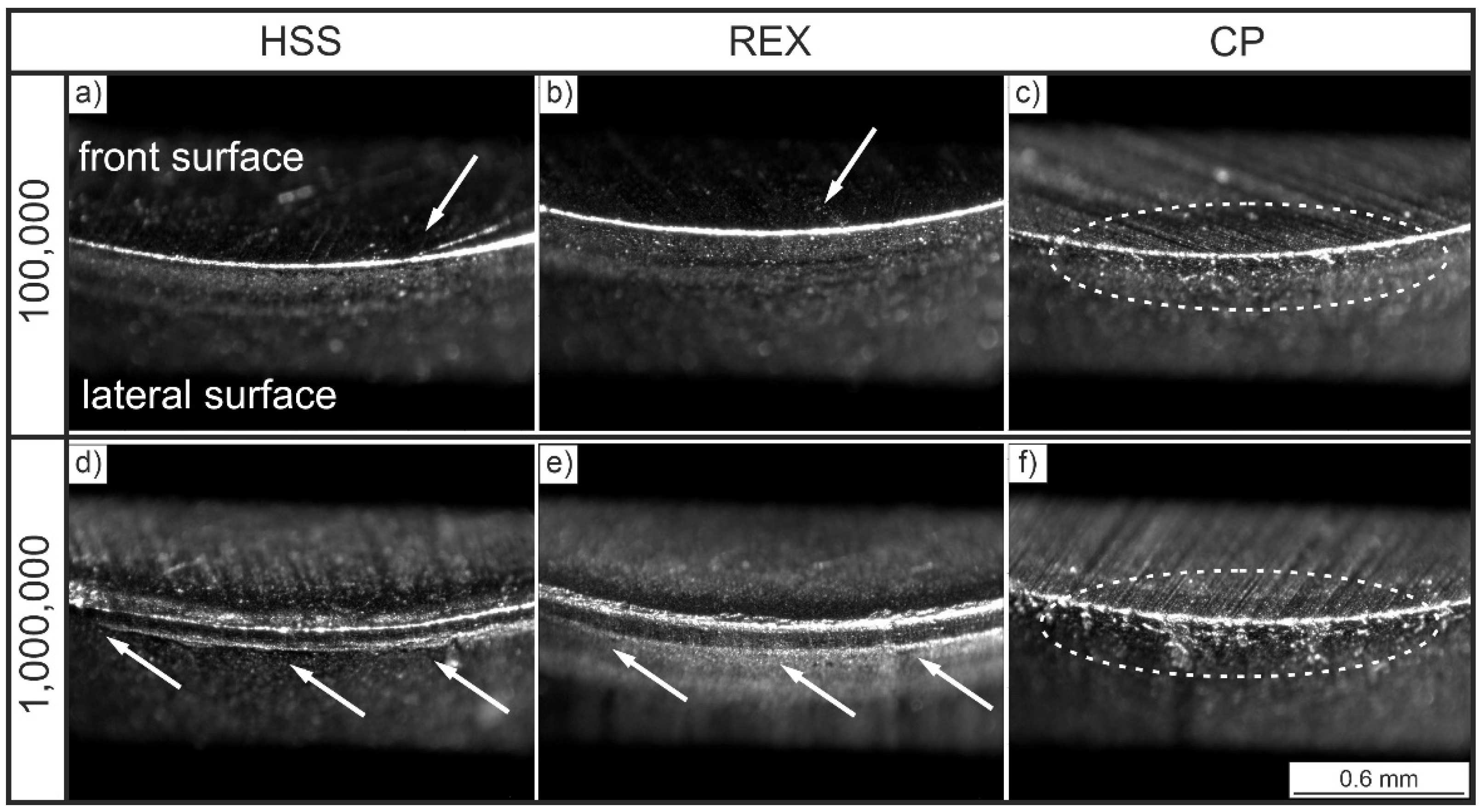
  • The punch made of the cheapest material (HSS) achieved the highest amount of burnish zone and thus the best cutting surface after 1,000,000 strokes.
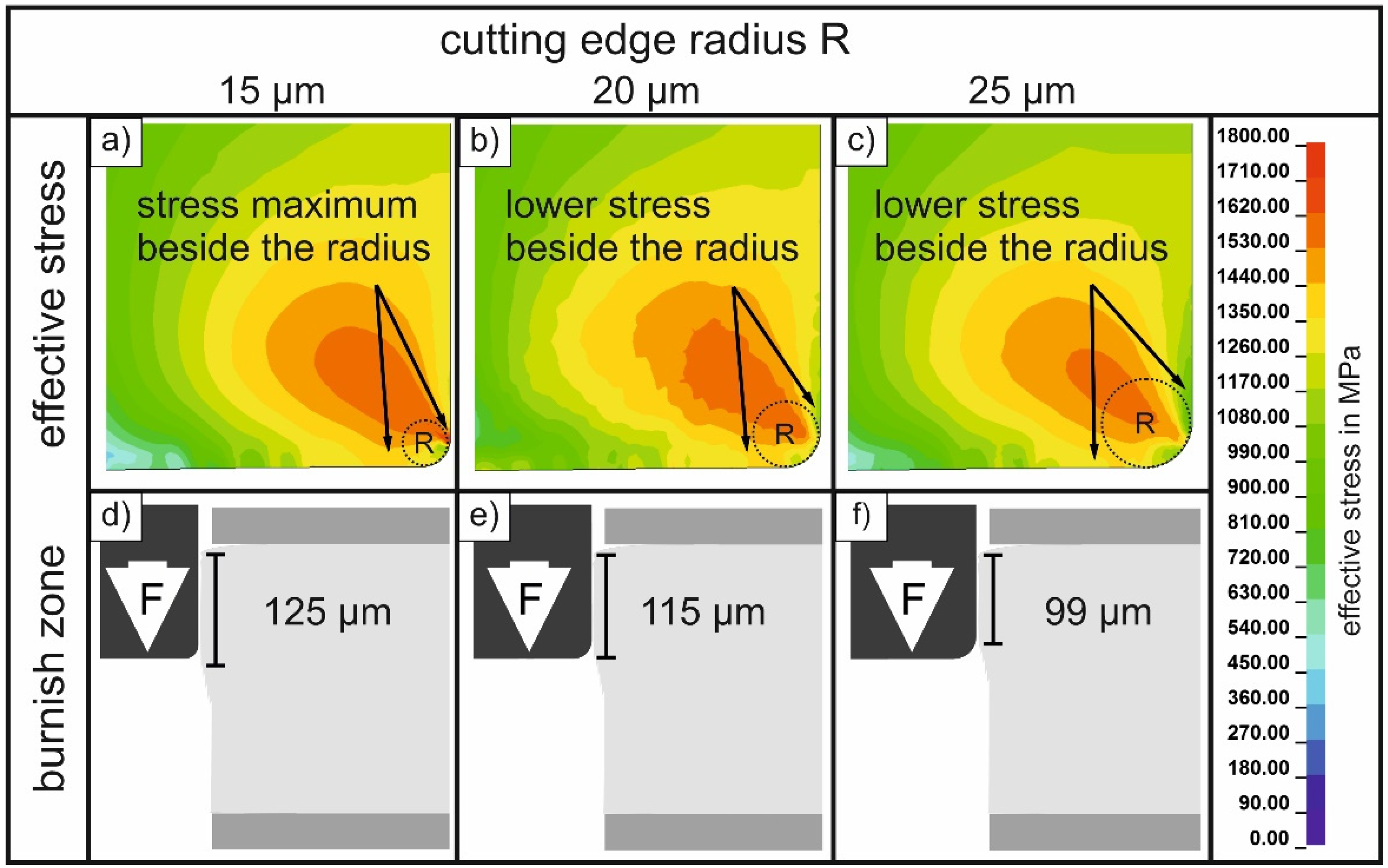
  • Increased material removal directly beside the cutting edge led to a reduction of the cutting edge radius in the HSS punches. This corresponds well to numerical simulation results indicating a very high local maximum stress directly beside the cutting edge radius. The weakening of the cutting edge caused by high material removal might lead to an earlier failure of HSS punches at higher stroke numbers in comparison to REX and CP.
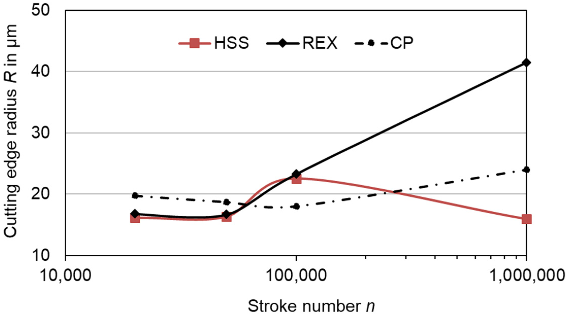
  • The evolution of the cutting edge radius varies for different punch materials. Depending on the number of strokes and the tool material, it can increase or decrease due to different wear mechanisms. This influences the cutting edge quality significantly.

Author Contributions

Conceptualization, S.W. and K.R.; methodology, S.W. and K.R.; investigation, S.W., K.R., M.N. and E.G.; resources, V.K.; writing—original draft preparation, S.W. and K.R.; writing—review and editing, S.W., M.N. and V.P.; visualization, S.W., K.R. and E.G.; supervision, V.P. and V.K.; project administration, K.R. and S.W.; funding acquisition, K.R. and M.N. All authors have read and agreed to the published version of the manuscript.

Funding

This research was funded by German Federation of Industrial Research Association (Arbeitsgemeinschaft industrieller Forschungsvereinigungen-AiF) and the Research Association for Steel Forming (Forschungsgesellschaft Stahlverformung e. V.-FSV). The project “Standmengenerhöhung von Schneidaktivelementen beim Scherschneiden federharter Bänder durch die quantitative Charakterisierung und Bewertung fertigungstechnischer Einflussgrößen” (grant number: IGF 19085 BR) has been accompanied by the German Association of Spring Manufacturers (Verband der deutschen Federnindustrie e. V.-VDFI).

Data Availability Statement

The authors confirm that the data to support the findings of this study are available within the article.

Acknowledgments

The authors would like to express their gratitude to Daniel Richter and Nancy Hagenauer for their support in sample preparation, microstructural characterization and cutting edge measurements.

Conflicts of Interest

The authors declare no conflict of interest.

References

  1. Merklein, M.; Wieland, M.; Lechner, M.; Bruschi, S.; Ghiotti, A. Hot stamping of boron steel sheets with tailored properties: A review. J. Mater. Process. Technol. 2016, 228, 11–24. [Google Scholar] [CrossRef]
  2. Sachnik, P.; Hoque, S.E.; Volk, W. Burr-free cutting edges by notch-shear cutting. J. Mater. Process. Technol. 2017, 249, 229–245. [Google Scholar] [CrossRef]
  3. Maiti, S.K.; Ambekar, A.A.; Singh, U.P.; Date, P.P.; Narasimhan, K. Assessment of influence of some process parameters on sheet metal blanking. J. Mater. Process. Technol. 2000, 102, 249–256. [Google Scholar] [CrossRef]
  4. Schmitz, F.; Winter, S.; Clausmeyer, T.; Wagner, M.F.X.; Tekkaya, A.E. Adiabatic blanking of advanced high-strength steels. CIRP Ann. 2020, 69, 269–272. [Google Scholar] [CrossRef]
  5. Nothhaft, K.; Suh, J.; Golle, M.; Picas, I.; Casellas, D.; Volk, W. Shear cutting of press hardened steel: Influence of punch chamfer on process forces, tool stresses and sheared edge qualities. Prod. Eng. 2012, 6, 413–420. [Google Scholar] [CrossRef]
  6. Pereira, M.P.; Weiss, M.; Rolfe, B.F.; Hilditch, T.B. The effect of the die radius profile accuracy on wear in sheet metal stamping. Int. J. Mach. Tools Manuf. 2013, 66, 44–53. [Google Scholar] [CrossRef]
  7. Shirzadian, S.; Bhowmick, S.; Alpas, A.T. Characterization of galling during dry and lubricated punching of AA5754 sheet. Adv. Ind. Manuf. Eng. 2021, 3, 100064. [Google Scholar] [CrossRef]
  8. Zeidi, A.; Ben Saada, F.; Elleuch, K.; Atapek, H. AISI D2 punch head damage: Fatigue and wear mechanism. Eng. Fail. Anal. 2021, 129, 105676. [Google Scholar] [CrossRef]
  9. Otroshi, M.; Meschut, G. Influence of cutting clearance and punch geometry on the stress state in small punch test. Eng. Fail. Anal. 2022, 136, 106183. [Google Scholar] [CrossRef]
  10. Hambli, R.; Richir, S.; Crubleau, P.; Taravel, B. Prediction of optimum clearance in sheet metal blanking processes. Int. J. Adv. Manuf. Technol. 2003, 22, 20–25. [Google Scholar] [CrossRef]
  11. Pereira, M.P.; Yan, W.; Rolfe, B.F. Wear at the die radius in sheet metal stamping. Wear 2012, 274–275, 355–367. [Google Scholar] [CrossRef]
  12. Babu, S.S.M.; Berry, S.; Ward, M.; Krzyzanowski, M. Numerical investigation of key stamping process parameters influencing tool life and wear. Procedia Manuf. 2018, 15, 427–435. [Google Scholar] [CrossRef]
  13. Narojczyk, J.; Werner, Z.; Piekoszewski, J. Analysis of the wear process of nitrogen implanted HSS stamping dies. Vacuum 2001, 63, 691–695. [Google Scholar] [CrossRef]
  14. Winter, S.; Nestler, M.; Galiev, E.; Hartmann, F.; Psyk, V.; Kräusel, V.; Dix, M. Adiabatic Blanking: Influence of Clearance, Impact Energy, and Velocity on the Blanked Surface. J. Manuf. Mater. Process. 2021, 5, 35. [Google Scholar] [CrossRef]
  15. Winter, S.; Galiev, E.; Nestler, M.; Psyk, V. Verschleißerscheinungen an PM und HM-Stempeln beim Stanzen. Z. Wirtsch. Fabr. 2020, 115, 621–624. [Google Scholar] [CrossRef]
  16. Kennedy, D.M.; Vahey, J.; Hanney, D. Micro shot blasting of machine tools for improving surface finish and reducing cutting forces in manufacturing. Mater. Des. 2005, 26, 203–208. [Google Scholar] [CrossRef] [Green Version]
  17. Harada, Y.; Mori, K. Effect of processing temperature on warm shot peening of spring steel. J. Mater. Process. Technol. 2005, 162–163, 498–503. [Google Scholar] [CrossRef]
  18. Bai, S.; Sha, Y.; Zhang, J. The effect of compression loading on fatigue crack propagation after a single tensile overload at negative stress ratios. Int. J. Fatigue 2018, 110, 162–171. [Google Scholar] [CrossRef]
  19. Keunecke, M.; Stein, C.; Bewilogua, K.; Koelker, W.; Kassel, D.; den Berg, H. van Modified TiAlN coatings prepared by d.c. pulsed magnetron sputtering. Surf. Coat. Technol. 2010, 205, 1273–1278. [Google Scholar] [CrossRef]
  20. Sergejev, F.; Peetsalu, P.; Sivitski, A.; Saarna, M.; Adoberg, E. Surface fatigue and wear of PVD coated punches during fine blanking operation. Eng. Fail. Anal. 2011, 18, 1689–1697. [Google Scholar] [CrossRef]
  21. Boing, D.; de Oliveira, A.J.; Schroeter, R.B. Limiting conditions for application of PVD (TiAlN) and CVD (TiCN/Al2O3/TiN) coated cemented carbide grades in the turning of hardened steels. Wear 2018, 416–417, 54–61. [Google Scholar] [CrossRef]
  22. Winter, S.; Stein, C.; Richter, K.; Höfer, M.; Sittinger, V.; Psyk, V.; Kräusel, V. Erprobung anwendungsadaptierter CVD-Diamantschichten beim Stanzen. Z. Wirtsch. Fabr. 2021, 116, 464–468. [Google Scholar] [CrossRef]
  23. Bensely, A.; Prabhakaran, A.; Mohan Lal, D.; Nagarajan, G. Enhancing the wear resistance of case carburized steel (En 353) by cryogenic treatment. Cryogenics 2005, 45, 747–754. [Google Scholar] [CrossRef]
  24. Das, D.; Dutta, A.K.; Ray, K.K. Sub-zero treatments of AISI D2 steel: Part I. Microstructure and hardness. Mater. Sci. Eng. A 2010, 527, 2182–2193. [Google Scholar] [CrossRef]
  25. Das, D.; Dutta, A.K.; Ray, K.K. Sub-zero treatments of AISI D2 steel: Part II. Wear behavior. Mater. Sci. Eng. A 2010, 527, 2194–2206. [Google Scholar] [CrossRef]
  26. Siebert, S.; Theisen, W.; Sirosh, V.A.; Razumov, O.N.; Oppenkowski, A.; Gavriljuk, V.G.; Skoblik, A.P.; Tyshchenko, A.I.; Petrov, Y.N. Low-temperature martensitic transformation and deep cryogenic treatment of a tool steel. Mater. Sci. Eng. A 2010, 527, 7027–7039. [Google Scholar] [CrossRef]
  27. Blinn, B.; Winter, S.; Weber, M.; Demmler, M.; Kräusel, V.; Beck, T. Analyzing the influence of a deep cryogenic treatment on the mechanical properties of blanking tools by using the short-time method PhyBaLCHT. Mater. Sci. Eng. A 2021, 824, 141846. [Google Scholar] [CrossRef]
  28. Richter, K.; Reuther, F.; Müller, R. A simulation-based approach to predict the springback behavior of ultra-high strength spring strips. Mater. Sci. Forum 2019, 949, 48–56. [Google Scholar] [CrossRef] [Green Version]
Figure 1. Stress-strain behavior of the used strip material (1.4310).
Jmmp 06 00038 g001
Figure 3. Schematic illustration of the punching process and important parameters (cutting edge radius, clearance). In addition, relevant cutting surface parameters (red marking) are shown.
Jmmp 06 00038 g003
Figure 4. Two-dimensional axisymmetric model of the punching setup with relevant parameters and local mesh sizes for the FE-Simulation.
Jmmp 06 00038 g004
Figure 5. Optical images of cutting surfaces of parts blanked with different punch materials (HSS (a), REX (b) and CP (c)) after 1,000,000 strokes. HSS-parts feature highest burnish zone with 129 µm.
Jmmp 06 00038 g005
Figure 6. Optical images of lateral surfaces of the three used punch materials after 100,000 (ac) and 1,000,000 (df) strokes.
Jmmp 06 00038 g006
Figure 7. Measured cutting edge radius R of the three investigated punch materials between 20,000 and 1,000,000 strokes. HSS punches exhibited the smallest cutting edge radius after these tests.
Jmmp 06 00038 g007
Figure 8. Stereomicroscopic images of the cutting edges of the three examined materials after 100,000 (ac) and 1,000,000 (df) strokes. Significant wear can be observed on the face and on the lateral surface of the HSS punches directly adjacent to the cutting edge.
Jmmp 06 00038 g008
Figure 9. Outline measurement of the face and the lateral surface and resulting cutting edge radius of HSS (a), REX (b) and CP (c) punches. The HSS punch shows a large amount of material removal directly next to the edge.
Jmmp 06 00038 g009
Figure 10. Results of finite element simulations of the resulting stress in the punch (ac) and burnish zone (df) for three different cutting edge radii (15, 20 and 25 µm).
Jmmp 06 00038 g010
Table 1. Chemical compositions in weight percentage of the used materials.
In Wt.-%1.4310HSSREXCP
C0.100.91.5
Si1.110.30.3
Mn1.150.30.3
Cr16.84.03.8
Mo0.685.15.3
Ni6.7
V 1.93.1
Co 8.518.00
W 6.29.782.00
Febalancebalancebalance
Table 2. Parameters for the sheet metal 1.4310 used for the Johnson–Cook model.
A in MPaB in MPaCnk
182415560.0130.190.59
Publisher’s Note: MDPI stays neutral with regard to jurisdictional claims in published maps and institutional affiliations.

