Article

Adapting the Surface Integrity of High-Speed Steel Tools for Sheet-Bulk Metal Forming

1
Institute of Materials Engineering, TU Dortmund University, Leonhard-Euler-Straße 2, 44227 Dortmund, Germany
2
Institute of Machining Technology, TU Dortmund University, Baroper Straße 303, 44227 Dortmund, Germany
*
Author to whom correspondence should be addressed.
J. Manuf. Mater. Process. 2022, 6(2), 37; https://doi.org/10.3390/jmmp6020037
Submission received: 16 February 2022 / Revised: 13 March 2022 / Accepted: 16 March 2022 / Published: 18 March 2022
(This article belongs to the Special Issue Surface Integrity in Metals Machining)

Abstract

:
New manufacturing technologies, such as Sheet-Bulk Metal Forming, are facing the challenges of highly stressed tool surfaces which are limiting their service life. For this reason, the load-adapted design of surfaces and the subsurface region as well as the application of wear-resistant coatings for forming dies and molds made of high-speed steel has been subject to many research activities. Existing approaches in the form of grinding and conventional milling processes do not achieve the surface quality desired for the forming operations and therefore often require manual polishing strategies afterward. This might lead to an unfavorable constitution for subsequent PVD coating processes causing delamination effects or poor adhesion of the wear-resistant coatings. To overcome these restrictions, meso- and micromilling are presented as promising approaches to polishing strategies with varying grain sizes. The processed topographies are correlated with the tribological properties determined in an adapted ring compression test using the deep drawing steel DC04. Additionally, the influence of the roughness profile as well as the induced residual stresses in the subsurface region are examined with respect to their influence on the adhesion of a wear-resistant CrAlN PVD coating. The results prove the benefits of micromilling in terms of a reduced friction factor in the load spectrum of Sheet-Bulk Metal Forming as well as an improved coating adhesion in comparison to metallographic finishing strategies, which can be correlated to the processed roughness profile and induced compressive residual stresses in the subsurface region.

1. Introduction

The performance and the tribological properties of forming processes are influenced by the tool-sided surface characteristics as well as modifications [1]. This includes, on the one side, the service life of the molds and dies as well as, on the other side, the manufacturing tolerances of the realized final geometry of the workpiece [2]. Especially, in the context of Sheet-Bulk Metal Forming—which represents a new approach of bulk forming operations on sheet metals to produce parts with integrated functional elements—where these challenges have not yet been fully solved [3,4]. Due to the high process forces of up to 2100 kN and complex biaxial and triaxial stress states during the forming operation [5], the active elements of dies and molds are subjected to high loads and stresses [6]. This promotes the need to develop tailored tribological functional surfaces, which are designed to withstand high process loads [7,8]. To overcome these challenges, the deposition of Cr-based nitride coatings deposited by physical vapor deposition (PVD) was found to improve the wear resistance of forming tools [9,10,11,12]. Nevertheless, the adhesion of the coating is sensitive to the upstream mechanical machining processes concerning the topography and the residual stresses in the surface near region of the substrate material [13,14] and therefore remains an unsolved challenge for the tool and mold manufacturing, especially for Sheet-Bulk Metal Forming processes.
For this reason, the manufacturing of the geometry of the forming tool as well as the processing of the final surface quality are essential steps for producing dies and molds made out of heat-treated high-speed steel (HSS) [15]. Established machining strategies for hardened tool steels are milling or grinding, which on the one side directly influence the topography as well as the residual stress state in the near-surface region [16,17]. The resulting compressive stresses, which are induced by the mechanical engagement of the cutting tool and the accompanying elasto-plastic deformation of the subsurface area, can increase fatigue performance and therefore the service life of the forming tool [18,19]. Investigations performed by Grove et al. examined the variation of compressive residual stresses between −1000 and −400 MPa by grinding with toric grinding pins, depending on the machining strategy, feed rate, and grain size of the abrasive medium [20]. In addition to the residual stresses of the subsurface zone, a reduction of the roughness profile can be achieved by adapting the grinding strategy [21]. Nevertheless, the surface quality of milled forming tools cannot be achieved by grinding processes [22,23,24]. Additional challenges resulting from the field of application in the Sheet-Bulk Metal Forming include the processing of filigree cavities to form the secondary functional shape elements [25]. These are often not sufficiently accessible due to the tool dimensions and cutting kinematics of grinding or macromilling processes. Manual and time-consuming polishing processes of functional elements or free-form surfaces are often necessary in order to achieve high requirements in terms of surface quality [26]. However, this procedure causes local fluctuations in terms of surface roughness as well as the final geometry, which is influenced by the varying experience of the person performing the polishing process. Depending on the selected post-processing strategy, this can lead to local deviations in the surface roughness as well as unfavorable residual stress states, which might cause an early failure of the forming tools [27,28].
Within the broad variety of mechanical manufacturing processes, a promising approach for the machining of heat-treated tool steels for Sheet-Bulk Metal Forming with a hardness of H > 60 HRC is micromilling [29]. First results presented by Twardy and Krebs prove the feasibility and benefits of the manufacturing technology for different tool steels with respect to a low roughness profile [30,31]. Further investigations were summarized in the contribution by Meijer and Biermann, in which suitable parameters were derived on the basis of the process forces determined as well as the wear behavior of the cutting tools [29]. Despite the demanding machining of heat-treated tool steels, stable manufacturing processes with the excellent surface qualities could be derived. For this reason, the potentials of a meso- and micromilling strategy of hardened HSS AISI M3:2 (ASP®2023) are presented as finishing process for the surfaces of forming tools and compared to metallographic polishing strategies. The processed surfaces are analyzed with respect to the resulting roughness profile and the residual stresses in the subsurface area as well as the tribological properties for Sheet-Bulk Metal Forming processes. For a further improvement of the wear-resistance of the processed surfaces, a magnetron sputtered CrAlN PVD coating is deposited which is evaluated in terms of the coating adhesion. The effects and interactions of the resulting roughness profile and residual stresses on the adhesion of the coating system are discussed. Additionally, the potentials of the presented alternative process routes for tool manufacturing were derived to identify the interactions between mechanical pre-treatment and coating adhesion for highly stressed forming tools.

2. Materials and Methods

2.1. Materials

Plane-parallel coin-shaped specimens made of the powder-metallurgical high-speed steel AISI M3:2 (ASP®2023) with a diameter of D = 40 mm and a thickness of t = 5 mm were used. Due to its homogenous microstructure and the even, dispersed distribution of small carbides, the material combines high hardness with high toughness and therefore provides excellent tribological properties within the context of highly stressed forming tools for cold forming operations [15,32]. These properties represent a particularly good suitability for the application field Sheet-Bulk Metal Forming. The chemical composition of the substrate material is presented in Table 1. Before the mechanical processing, the steel substrates were heat-treated in a vacuum furnace EU 80/1H 30 (Schmetz, Menden, Germany) using an austenitizing temperature of 1100 °C and quenched by nitrogen cooling to room temperature. Subsequently the specimens were annealed three times at 560 °C for a holding time of one hour resulting in a hardness of H = 11.27 ± 0.13 GPa (H = 62.4 ± 0.2 HRC).

2.2. Mechanical Sample Preparation

After the heat-treatment of the substrates, the topography of the face ground process showed a roughness profile of Ra = 371.6 ± 26.5 nm and Rz = 2205.4 ± 209.3 nm as well as a neutral level of residual stresses (σ = 0 ± 10 MPa). For the investigations, two different approaches of mechanical processing strategies were selected. On the one hand, the specimens were prepared by a sequence of fine grinding and polishing processes with polycrystalline diamond (PCD) suspensions by metallographic preparation to ensure a uniform adjustment of the surface roughness and continuous change of the residual stresses in the subsurface area. Detailed information about the individual steps of the selected preparation sequence as well as the used parameters are summarized in Table 2. Each procedure of the preparation was performed for 10 min.
In addition to the sequence of metallographic preparation steps, two different milling processes were selected, which were performed on the stress-free condition of the substrate material. The face circumferential milling strategies as well as further specifications of the used tools for the hard milling operations are illustrated in Figure 1. The processing parameters are based on previous studies [29,31]. Both processes were performed with a width of cut of 10 % of the tool’s diameter, resulting in an ae = 0.1 mm for the micromilling (MM) process and an ae = 0.4 mm for the mesomilling (M) strategy. Within the investigations the expression mesomilling is used for macromilling tools, which are used within the range of micromilling cutting parameters. Furthermore, a depth of cut of ap = 25 µm and a cutting speed of vc = 120 m/min were selected. The process strategy chosen was lubricant-free and all machining investigations were conducted on the micro machining center HSPC 2522 (KERN Microtechnik GmbH, Eschenlohe, Germany), which is particularly suitable for high-precision MM processes.

2.3. Tribological Investigations of Steel Surfaces

The evaluation of the friction was performed for the differently processed topographies under the load spectrum of Sheet-Bulk Metal Forming by using an adapted ring-compression test (RCT) [33]. The ferritic deep drawing steel DC04 was selected as material for the ring specimens, which was compressed from the initial height of s0 = 2 mm to s1 = 1 mm. The rings were compressed under a force of Fmax = 475 kN in a hydraulic press HZPUI 260/160-1000/1000 (SMG, Waghäusel, Germany) using 0.1 mL Beruforge 150DL (Carl Bechem, Hagen, Germany) as lubricant. An overview of the setup and test conditions is presented in Figure 2.
According to Male and Cockcroft, the friction can be evaluated by measuring the inner diameter of the rings, whereas a larger inner diameter represents lower friction factors [34]. By using the correlations of Equation (1), the friction factor m can be determined for the DC04 specimens according to the investigations of Löffler et al. [35]:
m = ( 0.07722 × D i + 0.9696 ) ( D i 5.834 )
The evaluation of the inner diameter of the compressed ring Di was performed by a tactile coordinate measuring device Prismo Vast ZMC550 (Carl Zeiss, Oberkochen, Germany) using a touch probe with a stylus and a 1 mm ruby ball. The inner contour was determined by approximately 300 measurement points for each ring.

2.4. PVD Coating Process

After the mechanical processing of the different surfaces, the specimens were cleaned in ethanol and acetone in an ultrasonic bath to remove residuals from prior manufacturing steps. For the coating process the specimens were fixed on a two-folded handling system and were exposed to a heating sequence resulting in a temperature of approximately 350 °C avoiding annealing effects of the substrate material. As an additional pre-treatment, a noble gas and a hollow cathode assisted etching process were performed to remove oxides and impurities on the surface of substrates before the actual deposition process, as presented in [36]. The CrAlN coating was synthesized using an industrial coating device CC800/9 Custom (CemeCon AG, Würselen, Germany) with two AlCr20 targets consisting of a monolithic Al body (purity 99.9%) and 20 Cr plugs (purity 99.9%) with a diameter of 15 mm placed along the erosion tracks. The cathodes operated in direct current (DC) mode with a power density of p = 11.36 W/cm² at a nitrogen-controlled pressure of p = 500 mPa using argon (ΦAr = 120 sccm) and krypton (ΦKr = 80 sccm) as noble gases. The thickness of the deposited coatings was kept constant for all samples with approximately 3 µm. The mechanical properties of the coating system were measured by nanoindentation according to the method proposed by Oliver and Pharr [37] and were only evaluated to a depth of 10% of the coating thickness to avoid any influence of the substrate material. The hardness was determined with H = 34.2 ± 2.7 GPa and a Young’s modulus of E = 385.4 ± 19.5 GPa which is in good accordance with previous investigations of the CrAlN systems, indicating a crystallization of the CrAlN phase in the fcc-structure [10,38,39].

2.5. Analytical Methods

The roughness profile of the surfaces was measured using a confocal white light microscope µsurf explorer (Nanofocus, Oberhausen, Germany) and analyzed with the software µsurf Analysis 7 (Digital Surf, Besançon, France) according to DIN EN ISO 4287. For high resolution imaging, an Olypmus 50x lens with a numerical aperture of AN = 0.5 was used.
The measurement of the residual stresses was conducted by a diffractometer Advanced D8 (Bruker AXS, Madison, WI, USA) equipped with a polycap with a point focus of D = 2 mm. As radiation source a Cu Kα anode with a photon energy of E = 8.048 keV (λ = 0.154 nm) was used. The acceleration voltage and current were set to U = 40 kV and I = 40 mA, respectively. Additionally, a Mn filter was placed in front of the detector to subtract the Cu-Kβ radiation. The analyses of the residual stresses were performed using the sin2ψ method [40] using the α-Fe (220) Bragg reflection with the mechanical properties and X-ray elastic constants (XEC) as summarized in Table 3 based on Eigenmann and Machenrauch [41]. For the 2Θ range an interval from 97 up to 101° with a step size of ΔΘ = 0.1° with an exposure time of t = 5 s was chosen. The measurements were conducted selecting equal distances for the sin²ψ values in the range from 0 to 0.5 with increments of Δsin² ψ = 0.0625 and rotation angles of φ = ±0; 45; 90; 135; 180; 225 and 270°.
The adhesion of the CrAlN coatings on the substrate was investigated by scratch-tests using a Revetester (CSM Instruments, Neuchatel, Switzerland) with a Rockwell C diamond tip (radius 200 µm). The scratches were performed at a length of 10 mm with a linearly increased load from 0 to 100 N. The investigations were performed and the critical loads were analyzed according to ISO 20502 [42]. To evaluate the influence of the anisotropic properties of the surface integrity three scratches were performed in feed and orthogonal direction of the cutting direction of the milling process using a scanning electron microscope (SEM) FE-JSEM 7001 (Jeol, Tokyo, Japan).

3. Results

3.1. Influence of the Processing Strategy on the Topography

The results of the differently processed topographies measured by confocal white light microscope are presented in Figure 3. Exemplarily, the 3D topographies of the polishing strategy with 1 µm diamond suspension (PA), the fine grinding process (FG), and the two different milling strategies (M and MM) are illustrated. Additionally, the corresponding roughness values and the material ratio parameters are presented for all conditions indicating a direct influence of the process strategy on the resulting roughness profile. For the surface of the polished sample PA, the lowest roughness values for the arithmetic mean roughness (Ra = 6.6 ± 0.6 nm) and the mean roughness depth (Rz = 51.5 ± 0.6 nm) could be observed, showing a smooth featureless topography, which is characteristic for a mirror-like surface. With an increasing grain size of the diamond abrasives (i.e., of the diamond suspension) as presented by the conditions PB, PC, and LP, the roughness values steadily rise which is caused by the differences in the material removal by unbound abrasive grains in the polishing and lapping process [43]. For this reason, the values are located in between the presented surface PA and FG. These findings can be traced back to the influence of the grain size and grain concentration leading to a change in the amount of engaging grains as well as the chip formation in the abrasive process [44]. Larger grain sizes foster a higher material removal per grain and therefore induce the differences in the roughness profile and chip formation [26,45]. In comparison to the values obtained for the polishing and lapping strategies, the surface of the fine ground sample FG possesses a rise of the roughness values which can be directly linked to the observed small scratches and furrows on the surface.
Comparing the metallographic manufactured surfaces with the roughness profile and the material ratio parameters of the two different face milling strategies, comparable topographies were produced with respect to the roughness values. Nevertheless, the 3D surface of the mesomilling process features cutting grooves in cutting direction, whereas the topography of the micromilling presents a smooth surface with hardly noticeable marks in feed direction. These differences in the topography can be explained by the selected width of cut (ae,m = 0.4 mm and ae,mm = 0.1 mm) as well as the different stiffness of both tools, which leads to different engagement situations caused by static deflection of the tool. Due to the lower stiffness of the smaller tool, the deflection is more pronounced, which results in visible milling marks only in the lateral area of the tool engagement. The more rigid large tool of the mesomilling process, however, is only marginally deflected due to the low engagement parameters in the micrometer range and thus stands orthogonally on the surface. This results in a number of overcuts on the already machined surface in addition to the traces of lateral engagement, resulting in a more complex surface topography [46]. Therefore, the result for mesomilling process is similar to the fine grinding strategy and the values of the micromilling are only slightly above the roughness level of the metallographic polishing strategy. In general, the processed surfaces show a characteristic topography of hardened tool steels milled with end mills, with no visible burr formation or noticeable ploughing effects caused by the subseeding of the critical chip thickness. For this reason, the micromilled surfaces indicate an excellent performance for the application field of Sheet-Bulk Metal Forming due to their low roughness profile [47,48]. In contrast to the topography presented for ground surfaces processed by toric grinding pins, considerably lower roughness values could be observed for the micro- and mesomilling process [21]. The results of smooth surfaces can be confirmed in the investigations on micromachining by Brinksmeier et al. for the heat-treated tool steel AISI D2 [49] and were additionally transferred to other coldwork and high-speed steels by Twardy and Krebs [30,31].

3.2. Residual Stresses in Subsurface Area

In addition to the characteristics of the roughness profile, another important aspect is the constitution of the subsurface area, which plays a crucial role in the tribological performance as well as the service life of molds and dies [27]. All specimens were exposed to mechanical processes and are therefore influenced by mechanical stresses and thermal effects during material removal, which directly influence the surface integrity [50]. As presented in Figure 4, for the polishing strategies PA and PB, an isotropic stress-free subsurface region was determined, revealing negligibly low tensile residual stresses. With an increasing grain size for the polishing strategy as well as for the fine grinding process, a nearly linear increase in the compressive residual stresses up to −800 MPa in dependency of the grain size can be observed. Although small differences between the orientation of the residual stresses are noticed within the range of 100 MPa, an independent evolution of the stresses for the polishing processes can be concluded. In contrast to the metallographic preparation, deviating results were observed for the milled surfaces. In mesomilling, in particular higher residual stress values could be determined in the cutting direction (σM = −828 ± 62.6 MPa). With each cutting pass and in particular for the overcuts of the tool, the uncut chip thickness reduces until it drops below the minimum chip thickness, leading to a strong plastic deformation of the material. This induces higher compressive residual stresses in the direction of the cutting movement exceeding possible thermal effects [31]. Due to the low feed rate compared to conventional milling processes as well as the small width of cut, this effect is even enhanced. Therefore, one may conclude that the higher ratio of material deformation in front of the cutting edge is the dominant effect which leads to higher mechanical stresses in the cutting direction, resulting in higher residual stresses. Additionally, this effect fosters a strong anisotropy of the stresses in the surface near region of the HSS, leading to low compressive residual stresses in feed direction (σM = −142 ± 62.6 MPa). In contrast to the previously discussed results, for the micromilling process a similar level of the induced compressive residual stresses can be observed which does not reveal the strong anisotropic characteristics as the mesomilling process. These correlations can be confirmed in XRD measurements by Twardy for heat-treated powder metallurgical HSS, which show a direct correlation between the selected width of cut and the resulting compressive residual stress state in surface near region [30]. For a smaller lateral width of a cut, an increase in the compressive residual stresses can be observed, which is due to the large number of overlapping tool engagements and the resulting multiple densifications of the processed surface. For comparable cutting parameters in the context of ae, compressive residual stresses in the range from −1500 to −800 MPa could be determined by Twardy, which were also subjected to the hardness of the machined material [30]. In addition, the topography provides initial indicators of the kinematics of the processes used and their influence on the residual stress state. The strongly anisotropic compressive stress state is reflected in the artifacts of the mesomilling process, whereas all other surfaces considered show no preferred direction.

3.3. Tribological Properties of the Surfaces for Sheet Bulk Metal Forming

In addition to the characteristics of the surface roughness and the constitution of the subsurface region, the condition of the surface topography has a major influence on the friction behavior, thereby determining the performance of the surface in application processes. The friction factor was investigated by means of a specially designed test for the load spectrum of Sheet-Bulk Metal Forming processes in the form of an adapted ring compression test [33]. The selected setup enables the determination of the friction factor under real contact stresses during forming based on the change of the inner diameter of the ring-shaped workpiece as a function of the anisotropic material properties of the sheet metals. The measured ring diameters produced in the RCT as well as the corresponding friction factors derived from the models of Löffler et al. are presented for the direction-dependent friction properties of the material DC04 in Figure 5 [35]. For all surfaces, an almost constant difference of the friction factors determined between the rolling direction and the orthogonal direction can be observed. This behavior can be attributed to the change in the microstructure of the sheet material and the associated sheet metal anisotropy caused by the upstream rolling process. The grain elongation in the workpiece material in rolling direction exhibits a lower friction level, since the density of grain boundaries and thus the inhabitation of the dislocation movements is stronger orthogonal to the rolling direction. This anisotropic effect was also reported in previous investigations of different surface modifications for the sheet materials DC04 and DP600 [51,52]. In general, for the level of the friction factor, low values are noticed, which are caused by the low roughness profile. Especially for the milled surface, although showing a slightly increased higher roughness, the friction factor is on the same level, clearly indicating the benefits of the processing strategy.
Besides the direction-dependent friction properties, a correlation between the friction factor and the roughness profile, in particular on the reduced peak heights Rpk was determined, indicating a reduced friction factor with decreasing roughness values, as illustrated in Figure 6. The only exception in this context is the polished surface PA, which demonstrates a slightly higher friction level compared to the PB condition. The parabolic development of the friction factor can be explained by the findings of Brinksmeier et al., who provided an explanation by discussing an optimal value for the roughness profile in terms of the friction for strip drawing tests [49]. Surfaces with a low roughness profile show an improved adhesive behavior, which leads to higher friction. If the roughness values exceed the optimum, abrasive effects and interlocking/clamping between the tool and the workpiece increase, which also leads to a higher friction. For this reason, Brinksmeier et al. defined an interval of 200 < Sa < 400 nm as ideal for strip drawing processes [49]. The results presented for the RCT indicate smaller roughness values for favorable tribological conditions but are subjected to the same effects. However, the tribological results presented for the milled surfaces show a similar low friction compared to the metallographic polished surfaces. These findings are supported by the results presented by Sieczkarek et al. and Krebs, which proved the low friction factors of micromilled surfaces and therefore underline the potential to influence the material flow for Sheet-Bulk Metal Forming processes [31,48].

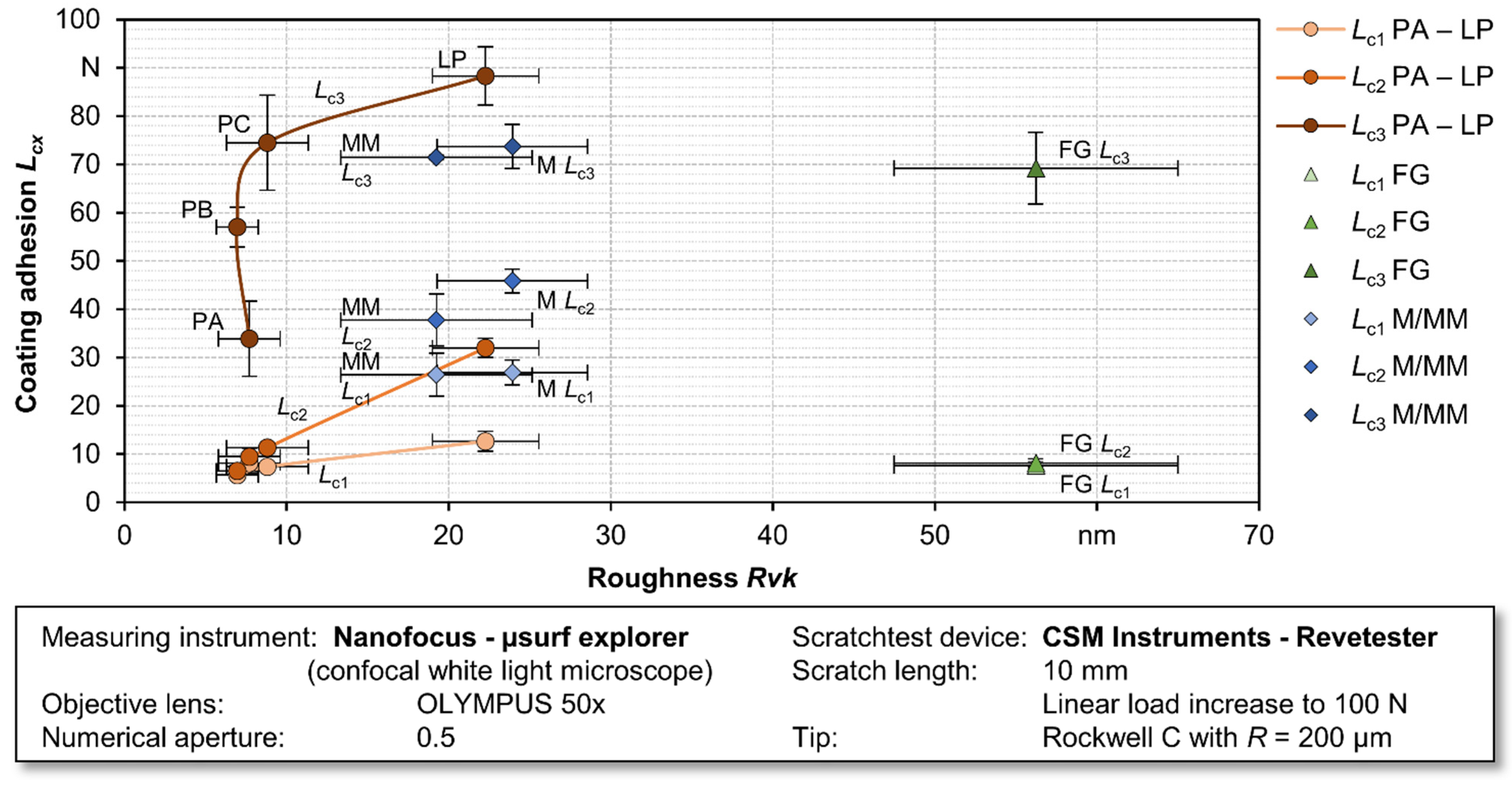
3.4. Influence of Processing Strategy on the Coating Adhesion

For an additional protection of the highly stressed tool surfaces in the load spectrum of Sheet-Bulk Metal Forming, PVD thin film systems offer improved tribological properties [12]. In order to ensure an extended service life and the tribological benefits of coated surfaces, the adhesion of the deposited coatings is a crucial factor. For this reason, the processed surfaces were evaluated in terms of the changes of the roughness profile by the subsequent deposition of a CrAlN thin film and the coating adhesion. The results obtained for the changes of the roughness profile are presented in Figure 7. In general, an increase in the roughness values compared to the initial state can be observed. This effect is distinctly noticeable for the polished surface conditions with a low roughness profile, which are due to the crystalline growth of the PVD layer and the associated increase in roughness [36]. In contrast, the topographies with a larger roughness profile in the initial state show a relatively small increase in roughness or even a reduction in the roughness parameters after the deposition process. This observation can be explained by the overgrowing of the grooves and pits on the surface of the sample FG in combination with a near-net shaped reproduction of the contour by the thin films. If the artifacts on the surface exceed a certain height, these are coated as presented by the cutting groves of the mesomilling process. In addition, these exposed areas foster shading effects during the thin film growth, which are reflected in an increase in the roughness profile. In contrast, the micromilled coated surface exhibits a comparable roughness to the polished surfaces, which can be attributed to a homogeneous growth behavior as a result of the smooth and defect-free topography. The same conclusions are drawn by Bromark et al., who found the same correlations for coated tool steels which were exposed to different pre-treatments [53]. These observations are confirmed by the analysis of the material ratio parameters. Compared to the initial state of all surface conditions, which has the roughness depth Rk as the dominating parameter (see Figure 2), a shift to higher values for the reduced valley depth Rvk is noticed after the coating process. This shift in the material ratio parameters results from the high-energetic growth and densification effects during the PVD deposition, which foster the formation of concave hollows in the thin films due to resputtering effects and thus leads to changed material ratio parameter. These correlations can be confirmed in the investigations by Harlin et al., who found a larger increase in the roughness parameters for the deposition of crystalline hard coatings on HSS substrates with different grinding pre-treatments compared to amorphous DLC coatings [54].
To evaluate the coating adhesion on the differently processed HSS substrates, an established method is the scratching by diamond tip to determine the critical loads according to ISO 20502 [42]. The evaluated results for the different failure mechanisms are summarized in Figure 8, separating the investigations for the milled surfaces in cutting and orthogonal to the cutting direction due to the previously discussed anisotropic properties of the surface integrity. The critical load Lc1 for the metallographic prepared surfaces show values below 20 N, whereas the milling processes indicate higher values with exception of the mesomilling strategy in feed direction. The same tendency for the differently processed surfaces was noticed for the critical load Lc2 for higher values, respectively. For the full delamination of the coating in the scratch track (Lc3) a constant increase in the load can be observed for the polishing strategies with a nearly constant level for the grinding and the milling processes in the range of 70 N. A further characteristic of the milled surfaces is the dependency of the coating adhesion on the kinematics of the machining process. This can be influenced by the kinematics of the milling process and the selected cutting parameters showing a correlation between the coating adhesion in and orthogonal to the direction of cut. For the critical loads Lc1 and Lc2 the thin film adhesion orthogonal to the cutting direction is more than twice as high compared to the parallel orientation. However, the values are on a similar level for the critical loads of Lc3. In the case of micromilling, only a small directional dependency could be determined, whereas the stated differences are in the range of the standard deviation of the measurements.
In order to correlate the obtained findings with the previously discussed results of the surface integrity, the critical loads are plotted against the reduced valley depth Rvk (Figure 9). For the correlation of the roughness profile, low values for the reduced valley depth Rvk led to a decreased coating adhesion which can especially be observed for the critical loads Lc1 and Lc2. With increasing Rvk values, the adhesion of the CrAlN thin films is improved, excluding the topography of the fine ground sample, which possesses significantly larger values due to scratches and furrows on the surface of the substrate. The same effect of a decreased adhesion for higher roughness values was reported by Huang et al. for the deposition of TiAlN coatings [55]. For smaller Rvk values these findings can be traced back to the effect of the hollows lowering the risk of delamination by compensating the induced shear stresses. The same tendency is determined for the critical load Lc3, which also defines Rvk < 10 nm as threshold for a sufficient coating adhesion. Especially for the milled surfaces, the processed roughness profile favors the coating adhesion, leading to an improved performance compared to the polishing processes PA und PB. The increase in the critical load Lc3 from PA to PC can be explained by the residual stresses.
Taking into consideration the residual stresses of the substrate material, a positive effect on the coating adhesion with increasing values can be observed, as presented in Figure 10. Due to the low residual stresses in the surface near region of the polished surfaces PA and PB, the findings of a low coating adhesion are supported. The deposited CrAlN systems present high compressive residual stresses due to the high energetic growth of the thin films [38,39], which therefore causes delamination effects due to the change of the residual stresses [13]. Additionally, this effect is superimposed by complex mechanical stresses in terms of ploughing, interface sliding and pulling of the coating by the applied scratch test [56]. The benefits of small differences between substrate and coating in terms of residuals stresses were also reported for different grinding and plasmanitriding pre-treatments enhancing the coating adhesion by tailoring the gradient of the residual stresses in the subsurface region [57,58]. The same effect was reported for sputtered TiAlN coatings on differently treated hot work steel AISI H11, which showed a direct relation between the critical loads and residual stresses gradient at the coating/substrate interface [14]. Based on the presented findings, the coating adhesion of sputtered CrAlN systems is subjected to complex interactions of the roughness profile and the residual stresses in the substrate material and needs to be specifically evaluated for each substrate/coating compound.
In order to evaluate the characteristics of the presented processes in terms of finishing strategies for highly stressed forming tools, Figure 11 presents the reduced valley depth Rvk over the induced residual stresses in the surface near region of the HSS material. Although the lowest roughness values can be achieved by the metallographic polishing strategies a low level of compressive residual stresses is induced, which is unfavorable for subsequent PVD coating deposition. In contrast to these results, one may highlight the characteristics of the milled topographies, which reveal on the one side only slightly higher roughness profiles, but on the side present high compressive residuals stresses to positively influence the coating adhesion. Comparable metallographic processes, e.g., fine grinding, are not capable to reach the properties of the meso- and micromilling processes. Additionally, the milled surfaces show improved tribological properties, and an enhanced coating adhesion. Finally, the metallographic processes do not allow the machining and finishing of complex forming tools, so that their use is only appropriate in the area of scientific investigations for determining correlations and setting up defined surface conditions.

4. Conclusions

Within the investigations, the potential and benefits of meso- and micromilling processes of heat-treated HSS steels in comparison to high quality surfaces in terms of metallographic preparations are presented. The differently processed surfaces are discussed with respect to their roughness profile and the induced residual stresses in the subsurface region. Additionally, the interactions of the roughness profile on the friction tests for the tribological load spectrum of Sheet-Bulk Metal Forming processes are presented. Furthermore, the suitability of the surface constitution for the deposition of wear-resistant CrAlN coatings is discussed based on the deviations in the surface roughness resulting from the coating deposition as well as the coating adhesion. The following conclusions can be drawn from the presented results:
  • The roughness profile of the meso- and micromilling processes configuration achieved nearly the same level of surface finishing as metallographic polishing processes. In contrast to the mesomilling strategy, which showed cutting groves, a defect-free featureless topography can be processed by micromilling with Ra < 15 nm.
  • High compressive residual stresses (σ ~ −800 MPa) can be induced by the micromilling processes showing a quasi-isotropic characteristic. The magnitude of residual stresses developed in polished surfaces is directly linked to the grain size of the diamonds.
  • In an adapted ring compression test for the sheet material DC04, the micromilled topography shows similar low friction factors in comparison to the polished surfaces, which can be linked to the reduced peak height Rpk.
  • The adhesion of the CrAlN coating can be directly correlated to the level of the compressive residual stresses in the subsurface region. Additionally, this correlation is superimposed by the roughness values in terms of the reduced valley height Rvk, which favors a good adhesion for Rvk > 10 nm and especially for the meso- and micromilling process.
In summary, the presented investigations confirm the potential of micromilling as finishing process, which needs to be further investigated in terms of the development of milling tools by designing the cutting-edge geometry and wear-resistant coatings systems as well as process strategies to further tailor the surface integrity.

Author Contributions

Conceptualization, W.T., D.S., A.M., T.P., E.K., N.F.L.D., L.H., D.B. and A.O.; methodology, W.T., D.S., A.M., T.P., E.K., N.F.L.D., L.H., D.B. and A.O.; investigation, D.S., A.M., T.P., E.K., N.F.L.D., L.H. and A.O.; resources, W.T., D.B.; writing—original draft preparation, W.T., D.S., A.M., T.P., E.K., N.F.L.D., L.H., D.B. and A.O.; writing—review and editing, W.T., D.S., A.M., T.P., E.K., N.F.L.D., L.H., D.B. and A.O.; visualization, D.S. and A.M.; supervision, W.T. and D.B. All authors have read and agreed to the published version of the manuscript.

Funding

This research was financially funded by the German Research Foundation (DFG) within the transregional collaborative research center SFB/TR73 “Manufacturing of complex functional components with variants by using a new sheet metal forming process–Sheet-bulk Metal Forming.” It presents results generated within the subprojects B2 (“Machining of molds with filigree structures for Sheet-Bulk Metal Forming”), B5 (“Application of nanostructured bionic thin layers to enhance the wear and friction behavior of forming tools by thin-walled sheet forming”), and T07 (“Functionalisation of Tool Topographies for Material Flow Control and Tool Life Optimisation”). Furthermore, the authors gratefully acknowledge the financial support of the German Research Foundation (DFG) within the project TI 343/187-1 and BI 126-1 (“Effects and interactions for interface and cutting-edge conditioning in hard micromachining”).

Data Availability Statement

The data presented in this study are available on request from the corresponding author. The data is not publicly available due to the required approval of the cooperating party in the transregional collaborative research center TR73.

Acknowledgments

The authors acknowledge the financial support by the German Research Foundation and TU Dortmund University within the funding program “Open Access Publishing”.

Conflicts of Interest

The authors declare no conflict of interest.

References

  1. Cao, J.; Brinksmeier, E.; Fu, M.; Gao, R.X.; Liang, B.; Merklein, M.; Schmidt, M.; Yanagimoto, J. Manufacturing of advanced smart tooling for metal forming. CIRPAnn. Manuf. Technol. 2019, 68, 605–628. [Google Scholar] [CrossRef]
  2. Gröbel, D.; Schulte, R.; Hildenbrand, P.; Lechner, M.; Engel, U.; Sieczkarek, P.; Wernicke, S.; Gies, S.; Tekkaya, A.E.; Behrens, B.A.; et al. Manufacturing of functional elements by sheet-bulk metal forming processes. Prod. Eng. Res. Dev. 2016, 10, 63–80. [Google Scholar] [CrossRef]
  3. Merklein, M.; Tekkaya, A.E.; Brosius, A.; Opel, S.; Kwiatkowski, L.; Plugge, B.; Schunck, S. Machines and Tools for Sheet-Bulk Metal Forming. Key Eng. Mater. 2011, 473, 91–98. [Google Scholar] [CrossRef]
  4. Merklein, M.; Allwood, J.M.; Behrens, B.-A.; Brosius, A.; Hagenah, H.; Kuzman, K.; Mori, K.; Tekkaya, A.E.; Weckenmann, A. Bulk forming of sheet metal. CIRP Ann. Manuf. Technol. 2012, 61, 725–745. [Google Scholar] [CrossRef]
  5. Merklein, M.; Koch, J.; Opel, S.; Schneider, T. Fundamental investigations on the material flow at combined sheet and bulk metal forming processes. CIRP Ann. Manuf. Technol. 2011, 60, 283–286. [Google Scholar] [CrossRef]
  6. Hetzner, H.; Koch, J.; Tremmel, S.; Wartzack, S.; Merklein, M. Improved Sheet Bulk Metal Forming Processes by Local Adjustment of Tribological Properties. J. Manuf. Sci. Eng. 2011, 133, 061011. [Google Scholar] [CrossRef]
  7. Löffler, M.; Andreas, K.; Engel, U.; Schulte, R.; Groebel, D.; Krebs, E.; Freiburg, D.; Biermann, D.; Stangier, D.; Tillmann, W.; et al. Tribological measures for controlling material flow in sheet-bulk metal forming. Prod. Eng. Res. Dev. 2016, 10, 459–470. [Google Scholar] [CrossRef]
  8. Merklein, M.; Lechner, M.; Gröbel, D.; Löffler, M.; Schneider, T.; Schulte, R.; Hildenbrand, P. Innovative approaches for controlling the material flow in sheet-bulk metal forming processes. Manuf. Rev. 2016, 3, 2. [Google Scholar] [CrossRef] [Green Version]
  9. Tillmann, W.; Stangier, D. Application of Nanostructured Bionic Thin Layers to Enhance the Wear and Friction Behavior of Tools for Sheet-Bulk Metal Forming. In Sheet Bulk Metal Forming; Merklein, M., Tekkaya, A.E., Behrens, B.A., Eds.; Springer: Berlin/Heidelberg, Germany, 2021; pp. 216–238. [Google Scholar]
  10. Behrens, B.-A.; Meijer, A.; Stangier, D.; Hübner, S.; Biermann, D.; Tillmann, W.; Rosenbusch, D.; Müller, P. Static and oscillation superimposed ring compression tests with structured and coated tools for Sheet-Bulk Metal Forming. J. Manuf. Processes 2020, 55, 78–86. [Google Scholar] [CrossRef]
  11. Behrens, B.-A.; Tillmann, W.; Biermann, D.; Hübner, S.; Stangier, D.; Freiburg, D.; Meijer, A.; Koch, S.; Rosenbusch, D.; Müller, P. Influence of Tailored Surfaces and Superimposed-Oscillation on Sheet-Bulk Metal Forming Operations. J. Manuf. Mater. Process. 2020, 4, 41. [Google Scholar] [CrossRef]
  12. Weikert, T.; Tremmel, S.; Stangier, D.; Tillmann, W.; Krebs, E.; Biermann, D. Tribological studies on multi-coated forming tools. J. Manuf. Processes 2020, 49, 141–152. [Google Scholar] [CrossRef]
  13. Denkena, B.; Breidenstein, B.; Lucas, H.; Keitel, M.; Tillmann, W.; Stangier, D. Influence of Residual Stresses in heat-treated High-Speed Steels on the Adhesion of CrAlN Coatings. J. Heat Treat. Mater. 2020, 75, 163–176. [Google Scholar] [CrossRef]
  14. Tillmann, W.; Grisales, D.; Stangier, D. Effects of AISI H11 surface integrity on the residual stresses and adhesion of TiAlN/substrate compounds. Surf. Coat. Technol. 2019, 357, 466–472. [Google Scholar] [CrossRef]
  15. Lange, K. Umformtechnik—Handbuch für Industrie und Wissenschaft—Band 4: Sonderverfahren, Prozeßsimulation, Werkzeugtechnik, Produktion, 2nd ed.; Springer: Berlin/Heidelberg, Germany, 1993; ISBN 3-540-55939-6. [Google Scholar]
  16. Denkena, B.; Grove, T.; Lucas, H. Interaction of load and residual stresses in sintered 1.3344 high speed steel. Adv. Mater. Res. 2014, 1018, 145–152. [Google Scholar] [CrossRef]
  17. Lucas, H.; Denkena, B.; Grove, T.; Krebs, E.; Kersting, P.; Freiburg, D.; Biermann, D. Analysis of Residual Stress States of Structured Surfaces Manufactured by High-Feed and Micromilling. HTM J. Heat Treat. Mater. 2015, 70, 183–189. [Google Scholar] [CrossRef]
  18. Wild, T.; Platt, T.; Biermann, D.; Merklein, M. Analysis of the Influence of Surface Modifications on the Fatigue Behavior of Hot Work Tool Steel Components. Materials 2021, 14, 7324. [Google Scholar] [CrossRef]
  19. Lange, K.; Kammerer, X.; Lange, K. Fließpressen—Wirtschaftliche Fertigung Metallischer Präzisionswerkstücke, 1st ed.; Lange, K., Kammerer, M., Pöhlandt, K., Schöck, J., Eds.; Springer: Berlin/Heidelberg, Germany, 2008; ISBN 978-3-540-30910-9. [Google Scholar]
  20. Grove, T.; Lucas, H.; Denkena, B. Residual stresses in grinding of forming tools with toric grinding pins. Procedia CIRP 2018, 71, 354–357. [Google Scholar] [CrossRef]
  21. Denkena, B.; Grove, T.; Lucas, H. Influences of grinding with Toric CBN grinding tools on surface and subsurface of 1.3344 PM steel. J. Mater. Process. Technol. 2016, 229, 541–548. [Google Scholar] [CrossRef]
  22. Biermann, D.; Baschin, A.; Krebs, E.; Schlenker, J. Manufacturing of dies from hardened tool steels by 3-axis micromilling. Prod. Eng. Res. Dev. 2011, 5, 209–217. [Google Scholar] [CrossRef]
  23. Biermann, D.; Krebs, E.; Sacharow, A.; Kersting, P. Using NC-path deformation for compensating tool deflections in micromilling of hardened steel. Procedia CIRP 2012, 1, 132–137. [Google Scholar] [CrossRef] [Green Version]
  24. Krebs, E.; Kersting, P. Improving the cutting conditions in the five-axis micromilling of hardened high-speed steel by applying a suitable tool inclination. Procedia CIRP 2014, 14, 366–370. [Google Scholar] [CrossRef] [Green Version]
  25. Landkammer, P.; Loderer, A.; Krebs, E.; Söhngen, B.; Steinmann, P.; Hausotte, T.; Kersting, P.; Biermann, D.; Willner, K. Experimental verification of a benchmark forming simulation. Key Eng. Mater. 2015, 639, 251–258. [Google Scholar] [CrossRef]
  26. Dambon, O.; Demmer, A.; Peters, J. Surface Interactions in Steel Polishing for the Precision Tool Making. CIRP Ann. 2006, 55, 609–612. [Google Scholar] [CrossRef]
  27. Wagner, K.; Völkl, R.; Engel, U. Tool life enhancement in cold forging by locally optimized surfaces. J. Mater. Process. Technol. 2008, 201, 2–8. [Google Scholar] [CrossRef]
  28. Lange, K.; Cser, L.; Geiger, M.; Kals, J.A.G. Tool Life and Tool Quality in Bulk Metal Forming. CIRP Ann. 1992, 41, 667–675. [Google Scholar] [CrossRef] [Green Version]
  29. Meijer, A.; Biermann, D. Machining of Molds with Filigree Structures for Sheet-Bulk Metal Forming. In Sheet Bulk Metal Forming; Merklein, M., Tekkaya, A.E., Behrens, B.A., Eds.; Springer: Berlin/Heidelberg, Germany, 2021; pp. 147–171. [Google Scholar]
  30. Twardy, S.M. Funktionsgerechte Fertigung von Mikroumformwerkzeugen Durch Mikrofräsen; Shaker: Aachen, Germany, 2014; ISBN 9783844031294. [Google Scholar]
  31. Krebs, E. Simulationsgestütze Mikrofräsbearbeitung Gehärteter Werkzeugstähle zur Herstellung Filigraner Formelemente und Funktionaler Oberflächenstrukturen; Vulkan-Verlag GmbH: Essen, Germany, 2018. [Google Scholar]
  32. Hoffmann, H.; Neugebauer, R.; Spur, G. (Eds.) Handbuch Umformen; Carl Hanser Verlag GmbH & Co. KG: München, Germany, 2012; ISBN 3446430040. [Google Scholar]
  33. Vierzigmann, U.; Schneider, T.; Koch, J.; Groebel, D.; Merklein, M.; Engel, U.; Hense, R.; Biermann, D.; Krebs, E.; Kersting, P.; et al. Untersuchung von Tailored Surfaces für die Blechmassivumformung mittels angepasstem Ringstauchversuch. In Tagungsband zum 2. Erlanger Workshop Blechmassivumformung; Merklein, M., Behrens, B.-A., Tekkaya, A.E., Eds.; Meisenbach: Bamberg, Germany, 2013; pp. 137–162. [Google Scholar]
  34. Male, A.T.; Cockcroft, M.G. A Method for the Determination of the Coefficient of Friction of Metals under Conditions of Bulk Plastic Deformation. J. Inst. Met. 1964, 93, 38–47. [Google Scholar]
  35. Löffler, M.; Schulte, R.; Freiburg, D.; Biermann, D.; Stangier, D.; Tillmann, W.; Merklein, M. Control of the material flow in sheet-bulk metal forming using modifications of the tool surface. Int. J. Mater. Form. 2019, 12, 17–26. [Google Scholar] [CrossRef]
  36. Tillmann, W.; Grisales, D.; Stangier, D.; Ben Jebara, I.; Kang, H. Influence of the etching processes on the adhesion of TiAlN coatings deposited by DCMS, HiPIMS and hybrid techniques on heat treated AISI H11. Surf. Coat. Technol. 2019, 378, 125075. [Google Scholar] [CrossRef]
  37. Oliver, W.C.; Pharr, G.M. An improved technique for determining hardness and elastic modulus using load and displacement sensing indentation experiments. J. Mater. Res. 1992, 7, 1564–1583. [Google Scholar] [CrossRef]
  38. Tillmann, W.; Stangier, D.; Hagen, L.; Schröder, P.; Krabiell, M. Influence of the WC grain size on the properties of PVD/HVOF duplex coatings. Surf. Coat. Technol. 2017, 328, 326–334. [Google Scholar] [CrossRef]
  39. Tillmann, W.; Hagen, L.; Stangier, D.; Krabiell, M.; Schröder, P.; Tiller, J.; Krumm, C.; Sternemann, C.; Paulus, M.; Elbers, M. Influence of etching-pretreatment on nano-grained WC-Co surfaces and properties of PVD/HVOF duplex coatings. Surf. Coat. Technol. 2019, 374, 32–43. [Google Scholar] [CrossRef]
  40. Noyan, I.C.; Cohen, J.B. Residual Stress—Measurement by Diffraction and Interpretation; Springer: New York, NY, USA, 1987. [Google Scholar]
  41. Eigenmann, B.; Macherauch, E. Röntgenographische Untersuchung von Spannungszuständen in Werkstoffen. Teil III. Fortsetzung von Matwiss. und Werkstofftechn. Heft 3/1995, S. 148–160 und Heft 4/1995, S. 199–216. Mater. Werkst. 1996, 27, 426–437. [Google Scholar] [CrossRef]
  42. DIN—Deutsches Institut für Normung e.V. DIN EN ISO 20502:2016—Hochleistungskeramik—Bestimmung der Haftung von Keramischen Schichten mit dem Ritztest; Beuth Verlag GmbH: Berlin, Germany, 2016. [Google Scholar]
  43. Evans, C.J.; Paul, E.; Dornfeld, D.; Lucca, D.A.; Byrne, G.; Tricard, M.; Klocke, F.; Dambon, O.; Mullany, B.A. Material Removal Mechanisms in Lapping and Polishing. CIRP Ann. 2003, 52, 611–633. [Google Scholar] [CrossRef] [Green Version]
  44. Komanduri, R.; Lucca, D.A.; Tani, Y. Technological Advances in Fine Abrasive Processes. CIRP Ann. 1997, 46, 545–596. [Google Scholar] [CrossRef]
  45. Klocke, F.; Dambon, O.; Filho, G.C. Influence of the polishing process on the near-surface zone of hardened and unhardened steel. Wear 2005, 258, 1794–1803. [Google Scholar] [CrossRef]
  46. Meijer, A.; Bergmann, J.A.; Krebs, E.; Biermann, D.; Wiederkehr, P. Analytical and Simulation-Based Prediction of Surface Roughness for Micromilling Hardened HSS. J. Manuf. Mater. Process. 2019, 3, 70. [Google Scholar] [CrossRef] [Green Version]
  47. Kersting, P.; Gröbel, D.; Merklein, M.; Sieczkarek, P.; Wernicke, S.; Tekkaya, A.E.; Krebs, E.; Freiburg, D.; Biermann, D.; Weikert, T.; et al. Experimental and numerical analysis of tribological effective surfaces for forming tools in Sheet-Bulk Metal Forming. Prod. Eng. Res. Dev. 2016, 10, 37–50. [Google Scholar] [CrossRef]
  48. Sieczkarek, P.; Wernicke, S.; Gies, S.; Tekkaya, A.E.; Krebs, E.; Wiederkehr, P.; Biermann, D.; Tillmann, W.; Stangier, D. Improvement strategies for the formfilling in incremental gear forming processes. Prod. Eng. Res. Dev. 2017, 11, 623–631. [Google Scholar] [CrossRef]
  49. Brinksmeier, E.; Riemer, O.; Twardy, S. Tribological behavior of micro structured surfaces for micro forming tools. Int. J. Mach. Tools Manuf. 2010, 50, 425–430. [Google Scholar] [CrossRef]
  50. Jawahir, I.S.; Brinksmeier, E.; M’Saoubi, R.; Aspinwall, D.K.; Outeiro, J.C.; Meyer, D.; Umbrello, D.; Jayal, A.D. Surface integrity in material removal processes: Recent advances. CIRP Ann. 2011, 60, 603–626. [Google Scholar] [CrossRef]
  51. Löffler, M.; Andreas, K.; Engel, U.; Weikert, T.; Tremmel, S.; Wartzack, S.; Stangier, D.; Tillmann, W.; Merklein, M. Surface modifications for adaption of tribological conditions in sheet-bulk metal forming processes. In Proceedings of the 12th International Conference the “A” Coatings, Hannover, Germany, 31 March–1 April 2016; Bobzin, K., Bouzakis, K.-D., Denkena, B., Maier, H.J., Merklein, M., Eds.; PZH: Hannover, Germany, 2016; pp. 13–20. [Google Scholar]
  52. Tillmann, W.; Stangier, D.; Schröder, P. Investigation and optimization of the tribo-mechanical properties of CrAlCN coatings using Design of Experiments. Surf. Coat. Technol. 2016, 308, 147–157. [Google Scholar] [CrossRef]
  53. Bromark, M.; Larsson, M.; Hedenqvist, P.; Olsson, M.; Hogmark, S. Influence of substrate surface topography on the critical normal force in scratch adhesion of TiN-coated steels. Surf. Coat. Technol. 1992, 52, 195–203. [Google Scholar] [CrossRef]
  54. Harlin, P.; Carlsson, P.; Bexell, U.; Olsson, M. Influence of surface roughness of PVD coatings on tribological performance in sliding contacts. Surf. Coat. Technol. 2006, 201, 4253–4259. [Google Scholar] [CrossRef]
  55. Huang, R.; Qi, Z.; Sun, P.; Wang, Z.; Wu, C. Influence of substrate roughness on structure and mechanical property of TiAlN coating fabricated by cathodic arc evaporation. Phys. Procedia 2011, 18, 160–167. [Google Scholar] [CrossRef] [Green Version]
  56. Holmberg, K.; Laukkanen, A.; Ronkainen, H.; Wallin, K.; Varjus, S. A model for stresses, crack generation and fracture toughness calculation in scratched TiN-coated steel surfaces. Wear 2003, 254, 278–291. [Google Scholar] [CrossRef]
  57. Denkena, B.; Grove, T.; Lucas, H.; Tillmann, W.; Stangier, D. Influence of PVD-coating manufacturing steps on the subsurface integrity of hardened and soft AISI M3:2 high speed steel. In Proceedings of the 12th International Conference the “A” Coatings, Hannover, Germany, 31 March–1 April 2016; Bobzin, K., Bouzakis, K.-D., Denkena, B., Maier, H.J., Merklein, M., Eds.; PZH-Verlag: Hannover, Germany, 2016; pp. 23–30. [Google Scholar]
  58. Tillmann, W.; Stangier, D.; Denkena, B.; Grove, T.; Lucas, H. Influence of PVD-coating technology and pretreatments on residual stresses for sheet-bulk metal forming tools. Prod. Eng. Res. Dev. 2016, 10, 17–24. [Google Scholar] [CrossRef]
Figure 1. (a) Kinematic of the used milling process; (b) SEM-image of the micromilling tool; (c) tool for the mesomilling process.
Jmmp 06 00037 g001
Figure 2. Setup and test conditions of the ring compression test.
Jmmp 06 00037 g002
Figure 3. The 3D topography of the surfaces: (a) polished PA; (b) fine ground FG; (c) mesomilling M; (d) micromilling MM process; (e) roughness values of arithmetic mean roughness Ra and mean roughness depth Rz; (f) material ratio parameters reduced valley depth Rvk, core roughness depth Rk, and reduced peak height Rpk.
Jmmp 06 00037 g003
Figure 4. Residual stresses in the subsurface area of the AISI M3:2 steel in dependency of the machining process.
Jmmp 06 00037 g004
Figure 5. Friction analysis of different surface topographies machined by varied processes and coated with CrAlN: (a) inner diameter of deformed rings Di and (b) corresponding values of the friction factor m.
Jmmp 06 00037 g005
Figure 6. Influence of the reduced peak height Rpk on the friction factor in Sheet-Bulk Metal Forming.
Jmmp 06 00037 g006
Figure 7. (a) Comparison of the topography before and after the deposition of the CrAlN coating; (b) material ratio parameters reduced valley depth Rvk, core roughness depth Rk and reduced peak height Rpk after coating.
Jmmp 06 00037 g007
Figure 8. Critical load values Lc1, Lc2, and Lc3 analyzed in a scratch test.
Jmmp 06 00037 g008
Figure 9. Correlation between surface roughness Rvk and the critical loads Lcx.
Jmmp 06 00037 g009
Figure 10. Correlation between the residual stresses in the HSS substrate and the CrAlN coating adhesion.
Jmmp 06 00037 g010
Figure 11. Correlation between the residual stresses in the HSS substrate and the roughness Rvk.
Jmmp 06 00037 g011
Table 1. Chemical composition of the high-speed steel AISI M3:2 (ASP®2023) (wt.%).
CCrMoWCoVFe
AISI M3:21.274.175.676.44-3.33balanced
Table 2. Parameter settings of the preparation steps.
Process StepDeclarationAbrasiveGrain Size (µm)Force
(N)
Rotation
(min−1)
Medium
Fine GrindingFGSiC1545300water
Lapping 9 µmLPPCD945150water
Polishing 6 µmPCPCD630150lubricant
Polishing 3 µmPBPCD330150lubricant
Polishing 1 µmPAPCD130150lubricant
Table 3. Properties for the calculation of the residual stresses.
Bragg Reflection2Θ
(°)
Young’s Modulus E
(MPa)
Poisson’s Ratio υ
(-)
XEC s1
(10−6 MPa−1)
XEC ½s2
(10−6 MPa−1)
α-Fe (220)98.94220,2640.28−1.275.81
Publisher’s Note: MDPI stays neutral with regard to jurisdictional claims in published maps and institutional affiliations.

