
Significant Reduction in Energy Consumption and Carbon Emission While Improving Productivity in Laser Drilling of CFRP Sheets with a Novel Stepped Process Parameter Parallel Ring Method


Abstract
:1. Introduction
2. Materials and Methods
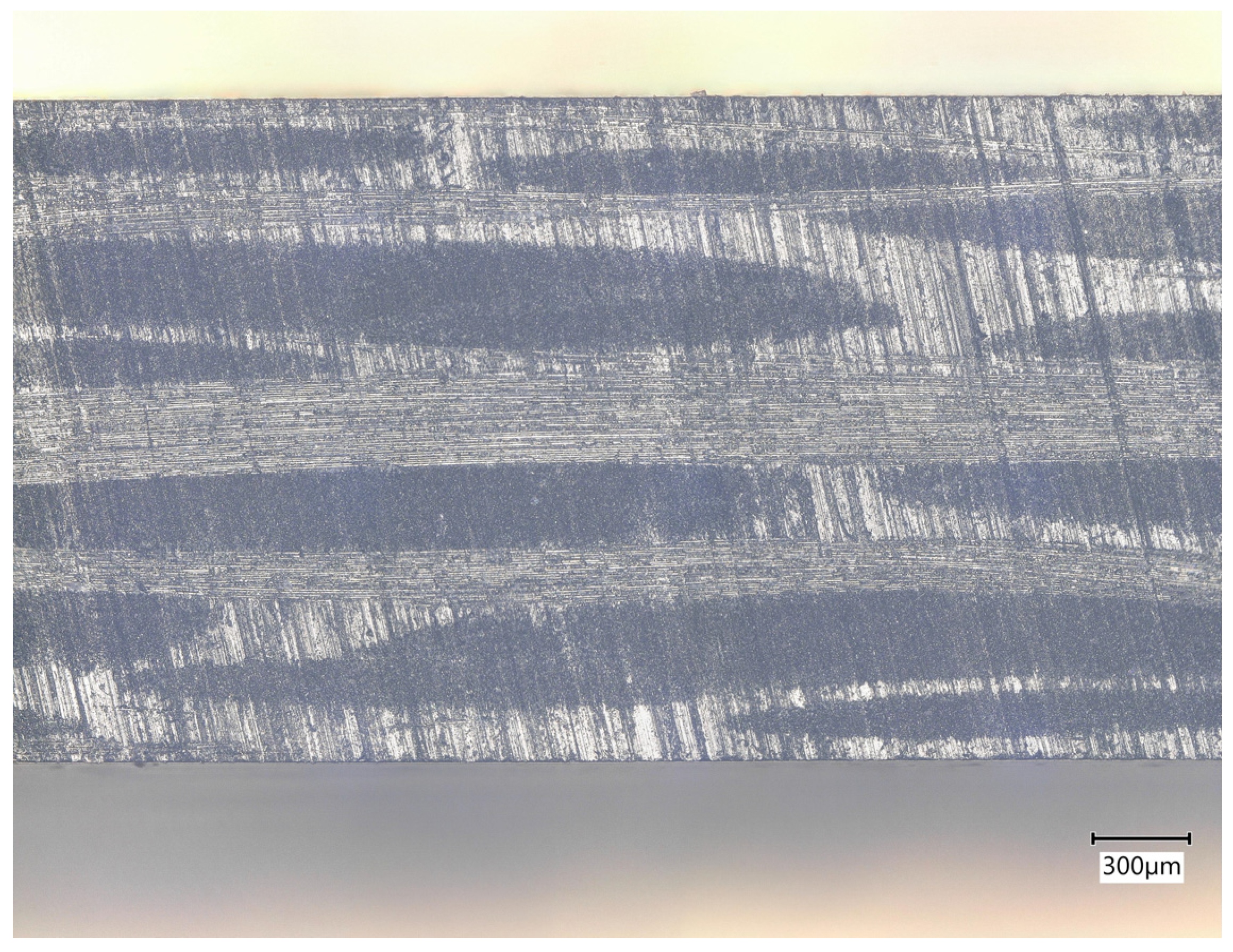
2.1. Workpiece Material
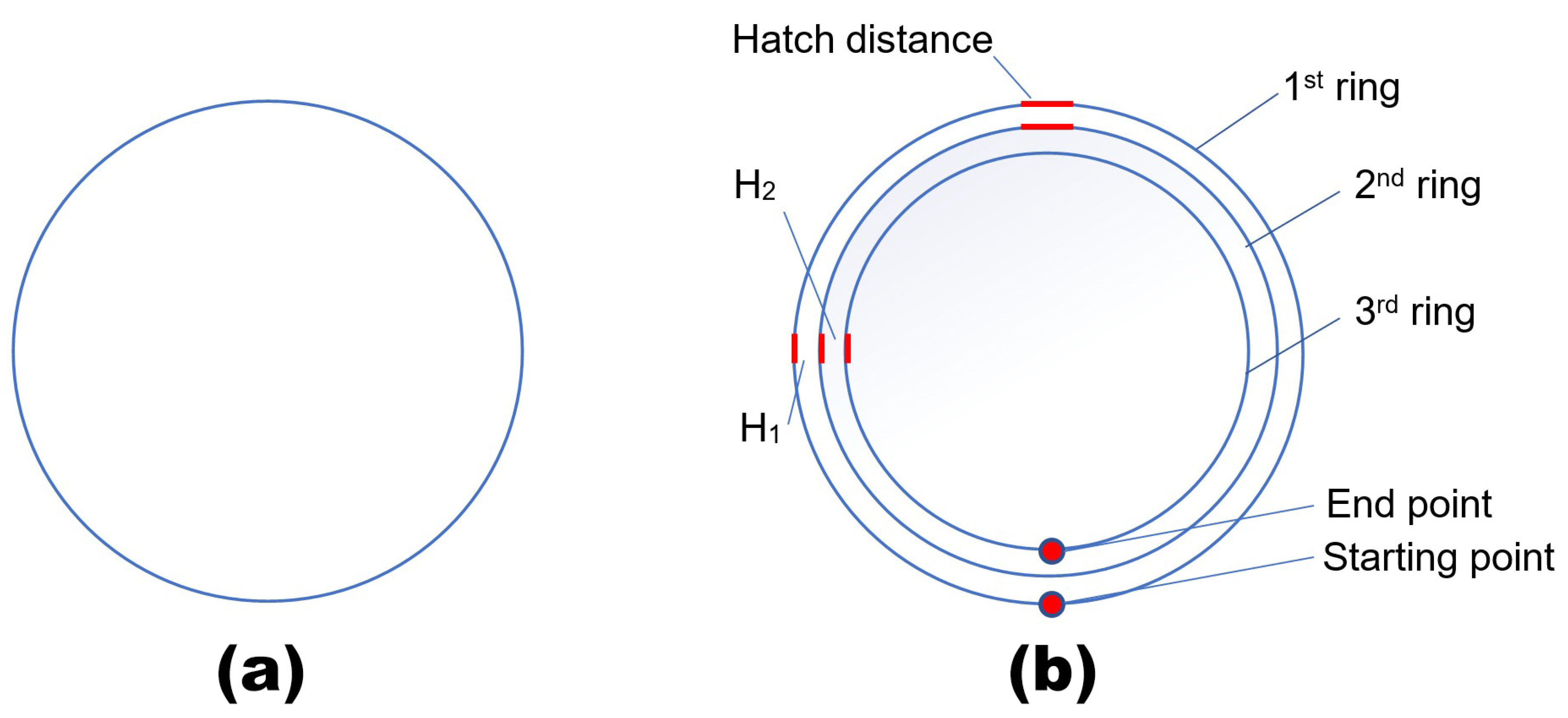
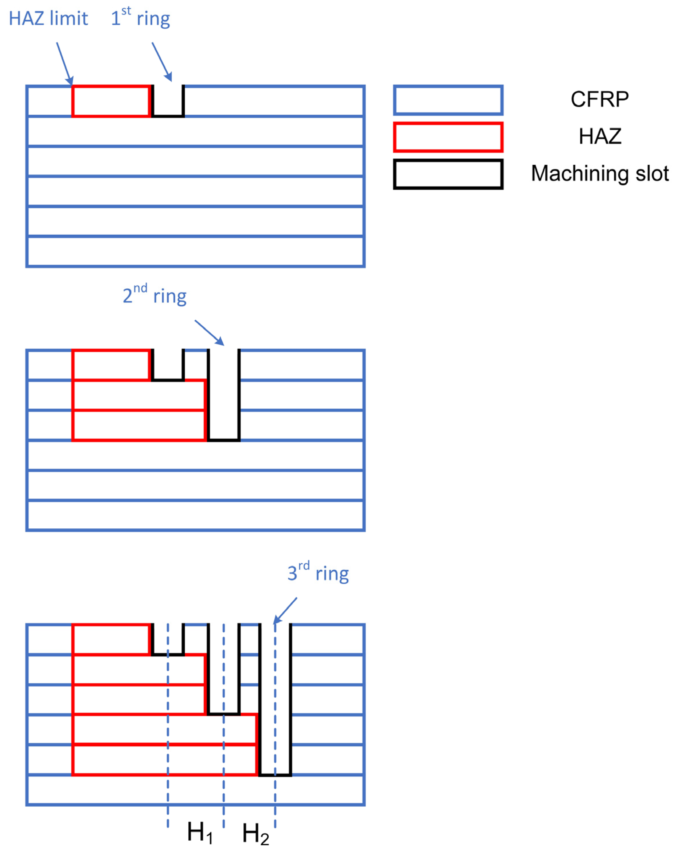
2.2. Stepped Laser Parameter Multiple Rings with Multiple Pass Drilling Strategy
2.3. Laser Processing System and Carbon Emission Estimation Method
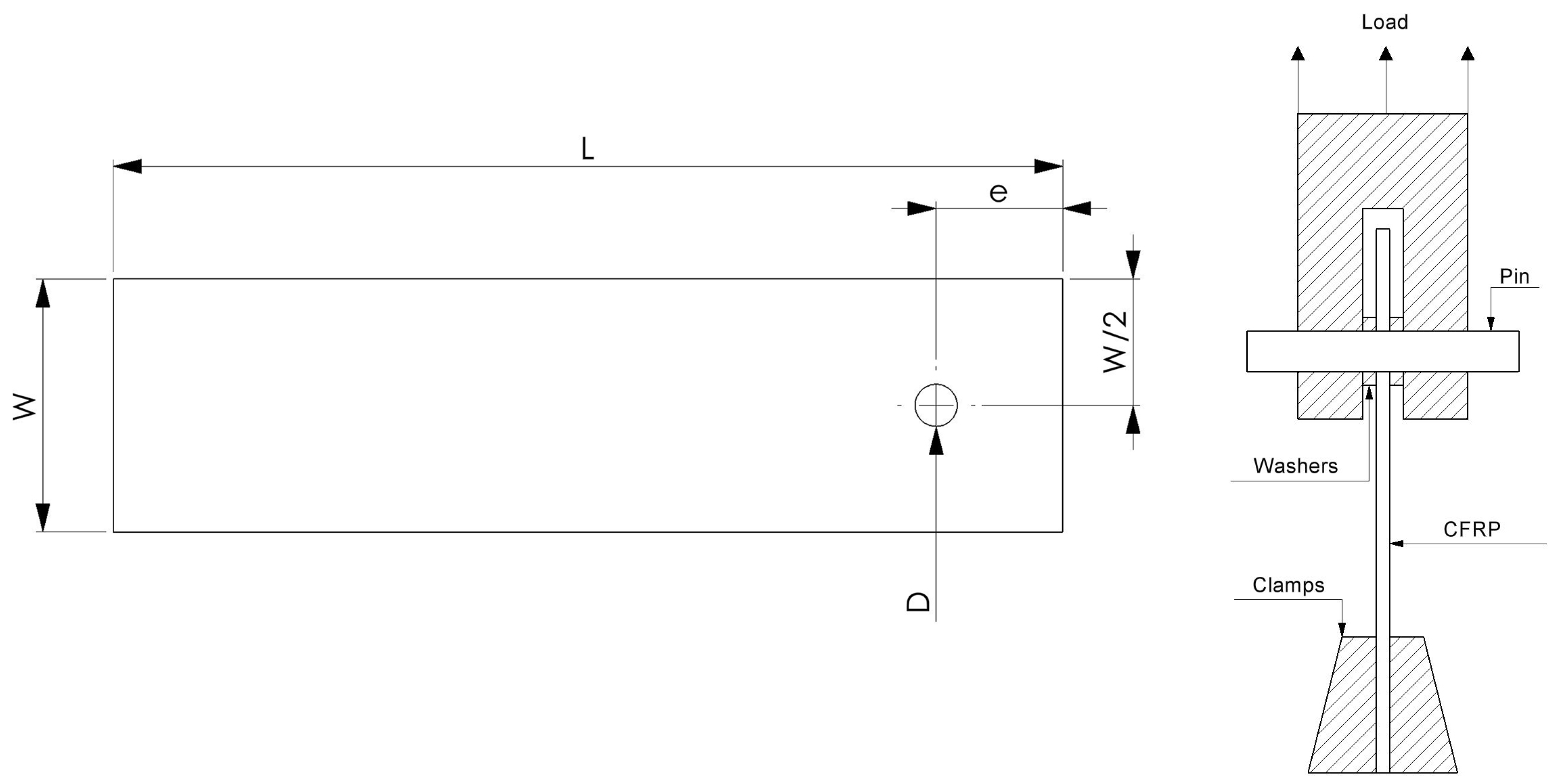
2.4. Bearing Strength Test of Laser Drilled CFRP Workpieces
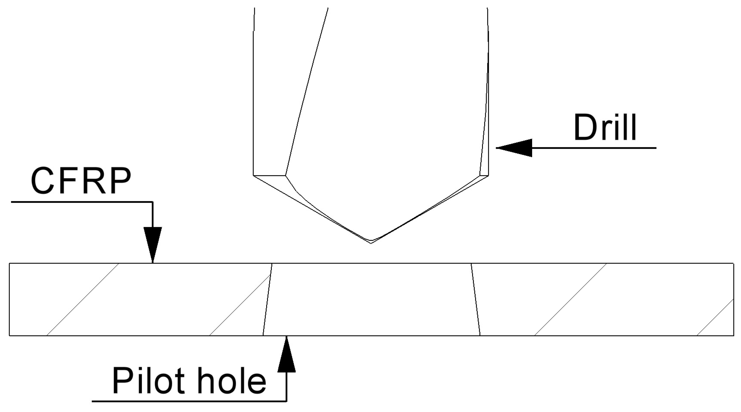
2.5. Mechanical Finishing Process

3. Results
3.1. Evaluation of Pulse Frequency Effect
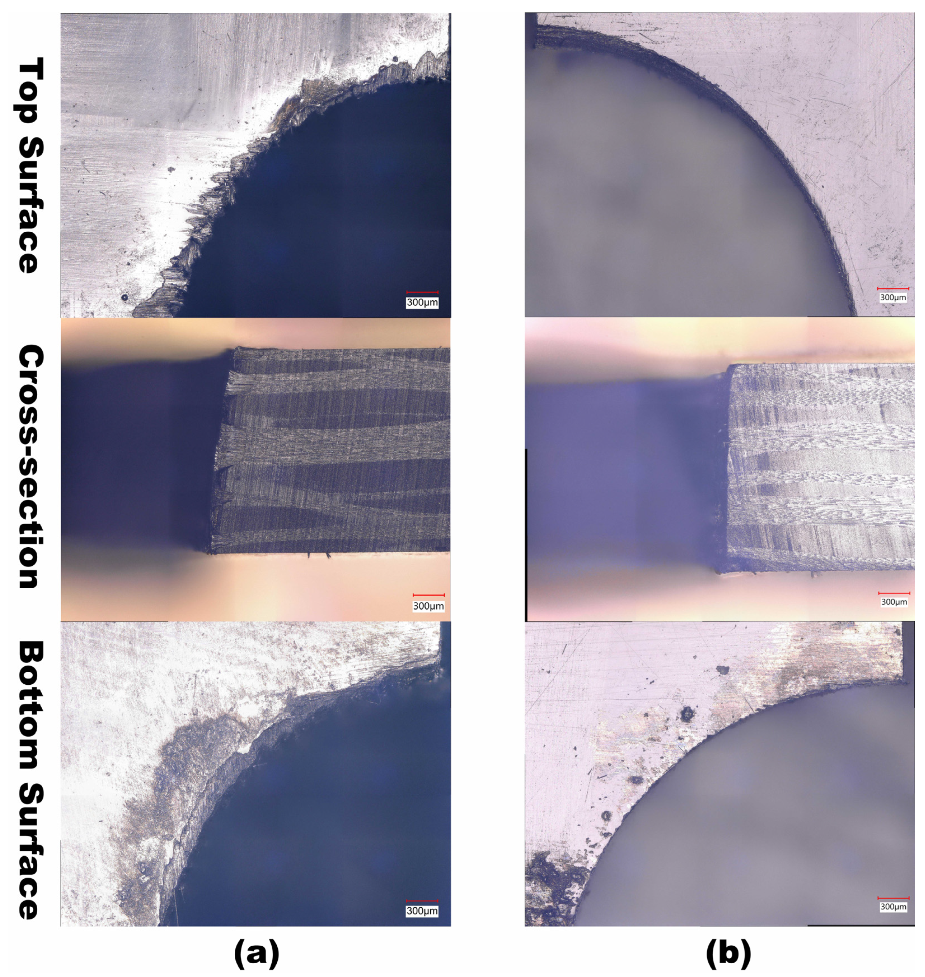
3.2. Evaluation of Drilling Quality for Each Method
3.3. Evaluation of Energy Consumption and Carbon Footprints
3.4. Evaluation of Bearing Strength
3.5. Mechanical Finishing
4. Discussion
5. Conclusions
- The stepped laser parameter multiple-ring drilling strategy leads to a 78.54% improvement in drilling time, i.e., over 300% increase in productivity, while reducing energy consumption by 78.10% compared with that of the constant laser parameter multiple-ring drilling method.
- The carbon emission from the stepped laser parameter multiple-ring drilling method is reduced to 5.15 gCO2, less than a quarter of that in the constant laser parameter multiple-ring drilling method of 23.52 gCO2.
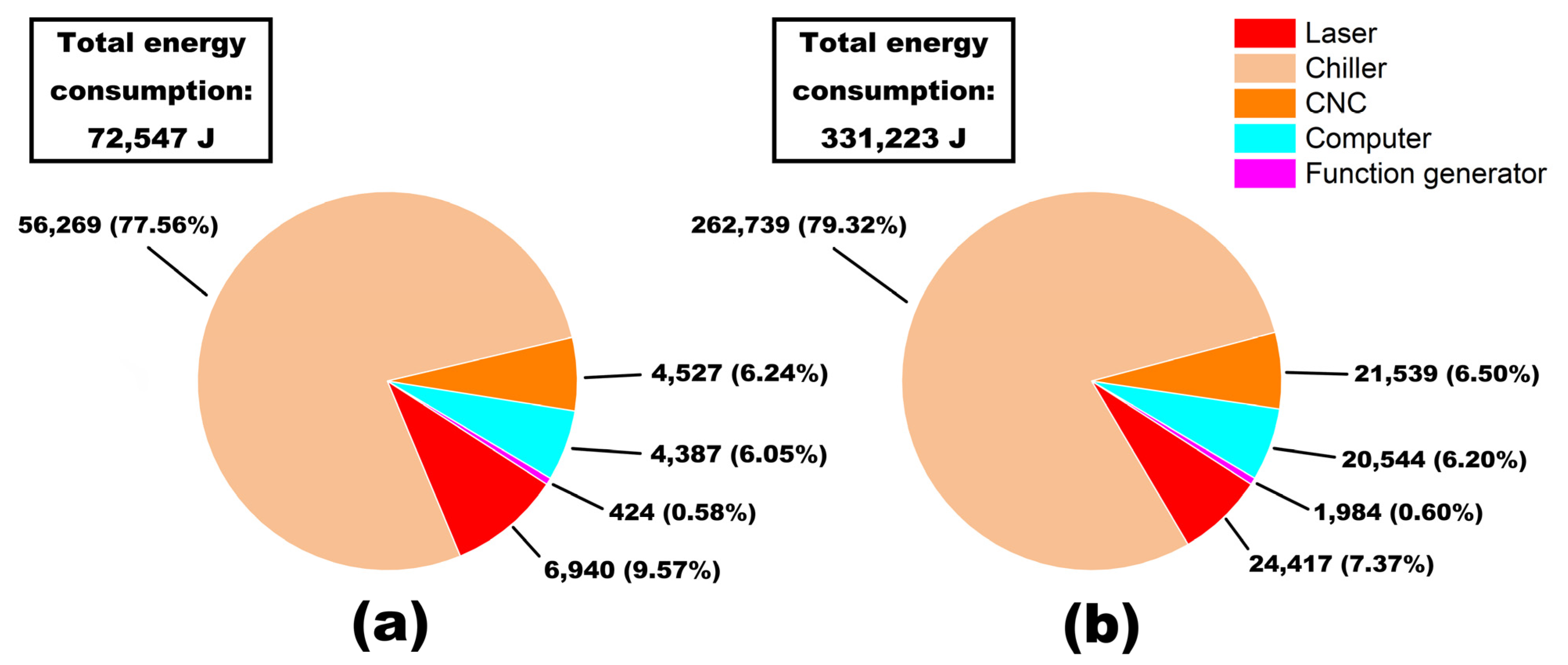
- The specific energy consumption to remove 1 mg of CFRP in a process period by the stepped laser parameter multiple-ring drilling method and the constant laser parameter multiple-ring drilling method is 3.82 × 10⁹ J/kg and 1.75 × 10¹⁰ J/kg, respectively.
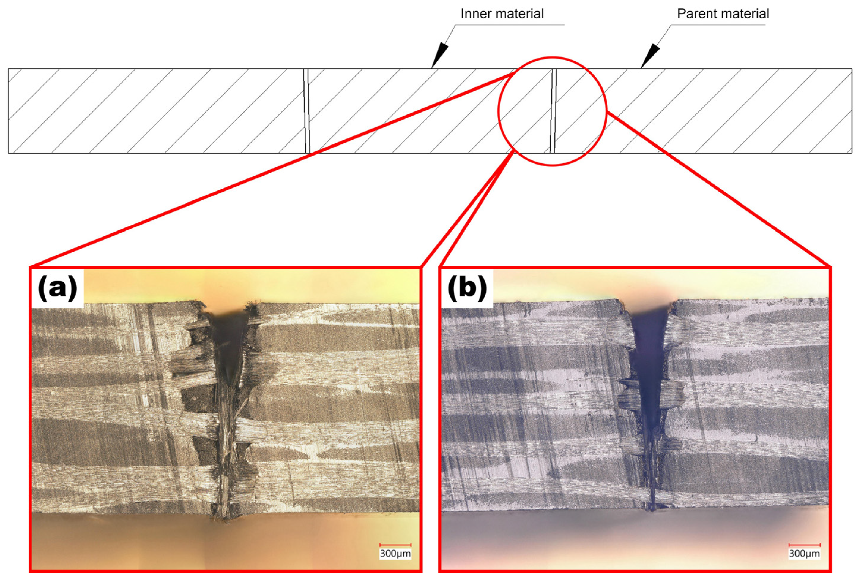
- The key reason for this significant reduction in drilling time and energy requirement is the increase in energy input for the inner rings for the more rapid removal of the material, while the lower energy input generated outer ring provided a shield trench to stop the heat transition into the parent material.
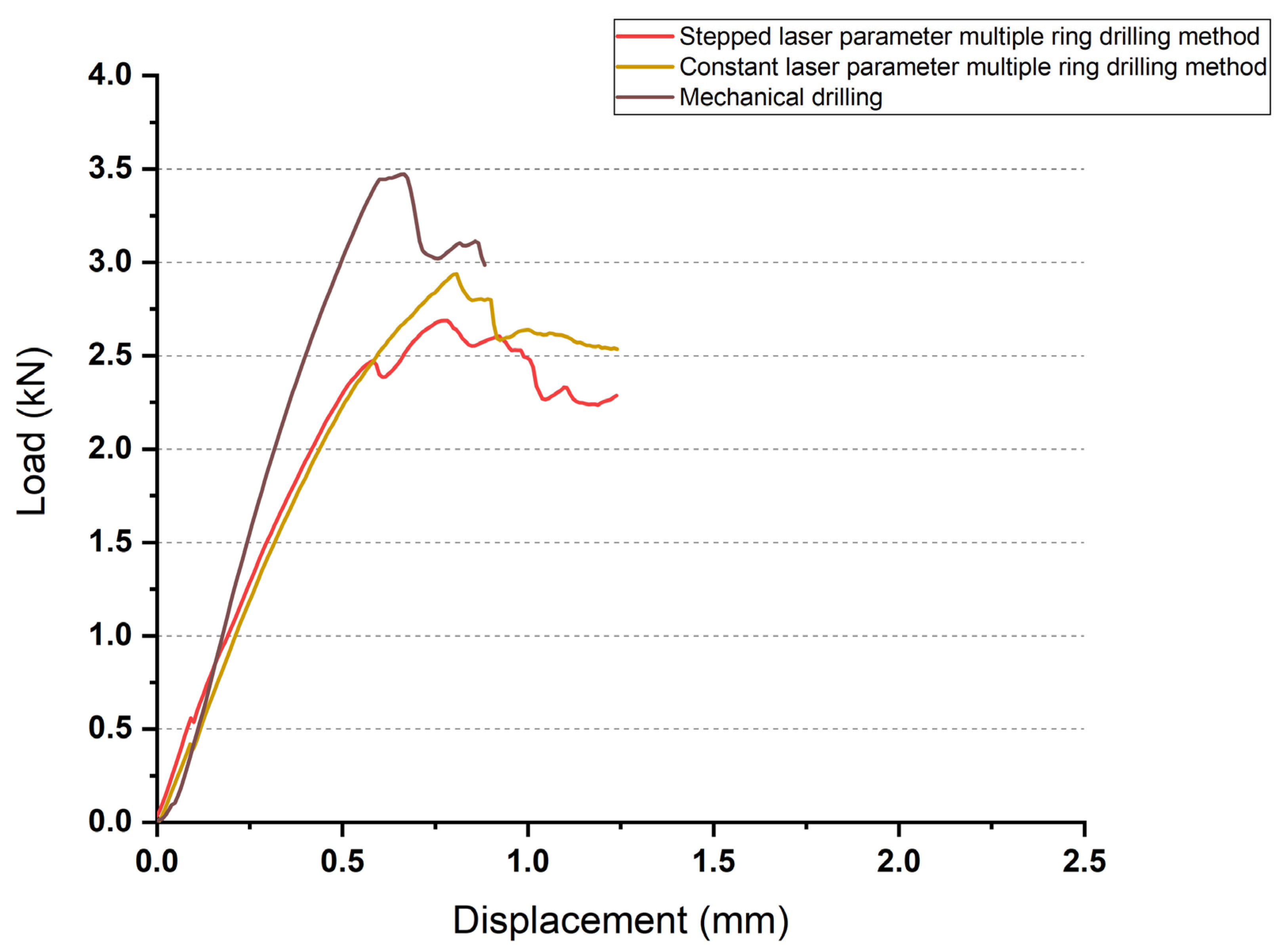
- Mechanical bearing response test shows that a laser drilled hole via stepped laser parameter multiple-ring drilling method has similar maximum failure load and load–displacement trend as that of samples drilled via constant laser parameter multiple-ring drilling method, but lower than that drilled mechanically.
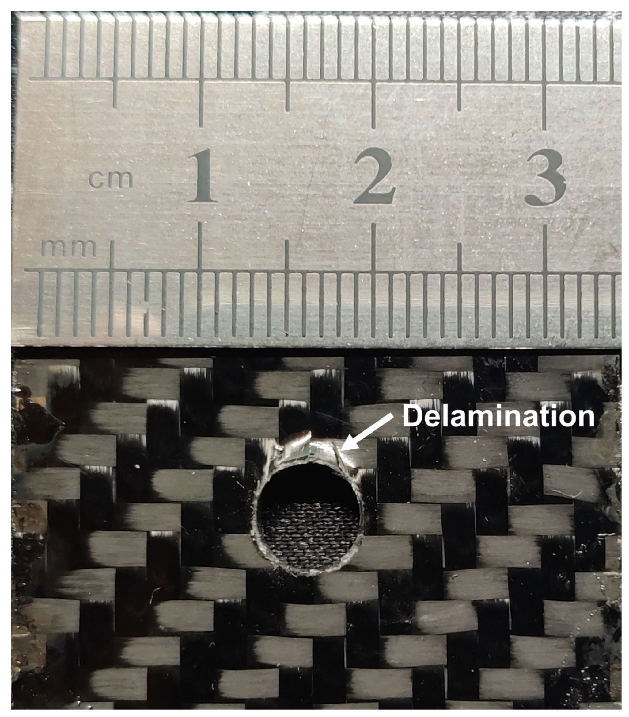
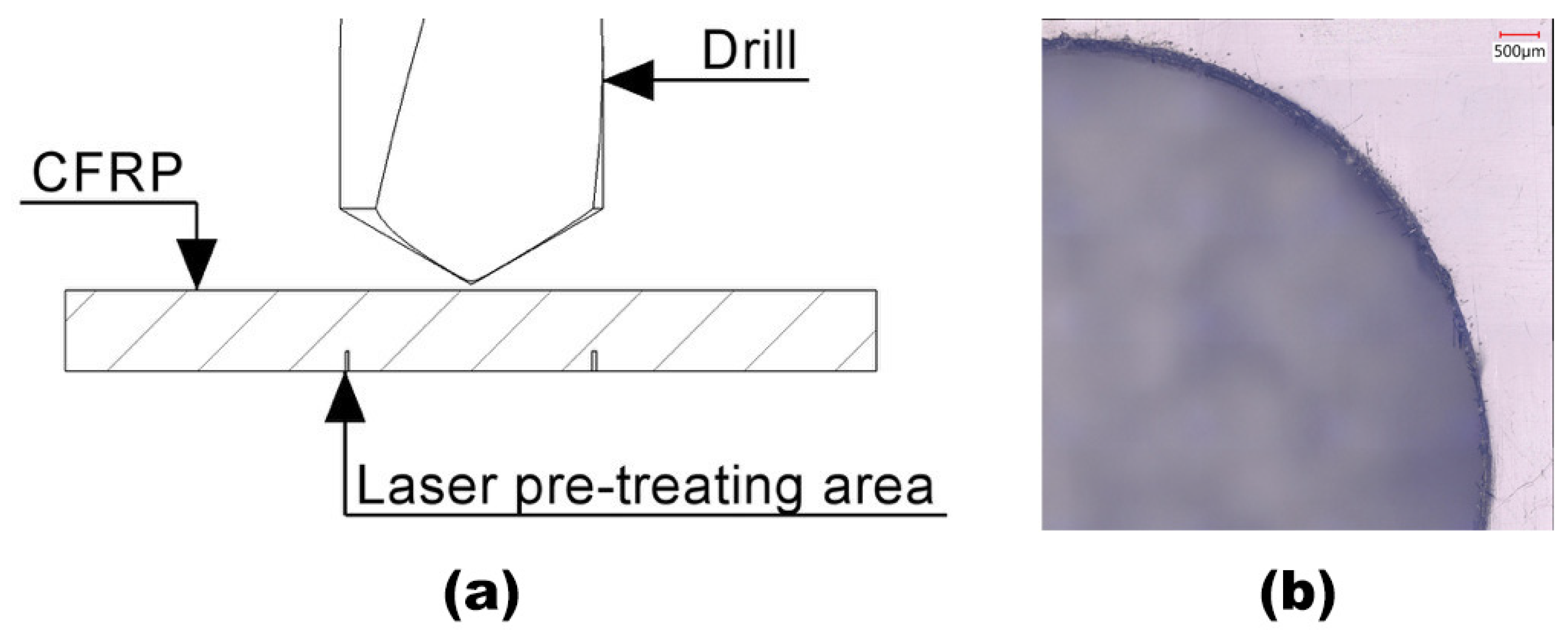
- The mechanical finishing process shows that a reversed-feed drilling strategy was able to suppress delamination at the hole exit without using supporting material and a specially designed drilling tool.
- With this new method, one can simultaneously minimise the drilling time and reduce environmental impact without sacrificing much on the drilling quality.
- A new combined rapid laser pre-scribing followed by mechanical hole drilling has been briefly demonstrated to avoid fibre delamination at the hole exit.
- The current study shows that laser drilling time (53 s) is still considerably longer than that for mechanical drilling (about 2 s), although the laser drilling eliminates the tool wear and fibre delamination at the hole exit. With the availability of high-power picosecond and femtosecond lasers, both drilling time and drilling quality can be further improved.
Author Contributions
Funding
Institutional Review Board Statement
Informed Consent Statement
Data Availability Statement
Acknowledgments
Conflicts of Interest
References
- Geng, D.; Liu, Y.; Shao, Z.; Lu, Z.; Cai, J.; Li, X.; Jiang, X.; Zhang, D. Delamination formation, evaluation and suppression during drilling of composite laminates: A review. Compos. Struct. 2019, 216, 168–186. [Google Scholar] [CrossRef]
- Staehr, R.; Bluemel, S.; Jaeschke, P.; Suttmann, O.; Overmeyer, L. Laser cutting of composites—Two approaches toward an industrial establishment. J. Laser Appl. 2016, 28, 022203. [Google Scholar] [CrossRef]
- Ebewele, R.O. Polymer Science and Technology; CRC Press: Boca Raton, FL, USA, 2000; ISBN 9781420057805. [Google Scholar]
- Pastuszak, P.D.; Muc, A. Application of composite materials in modern constructions. Key Eng. Mater. 2013, 542, 119–129. [Google Scholar] [CrossRef]
- Chung, D.D.L. Carbon Fiber Composites; Elsevier: Amsterdam, The Netherlands, 2012; ISBN 0750691697. [Google Scholar]
- Sheikh-Ahmad, J.Y. Machining of Polymer Composites; Springer: New York, NY, USA, 2009; ISBN 9780387355399. [Google Scholar]
- Salama, A.; Li, L.; Mativenga, P.; Whitehead, D. TEA CO2 laser machining of CFRP composite. Appl. Phys. A Mater. Sci. Process. 2016, 122, 497. [Google Scholar] [CrossRef] [Green Version]
- John, K.M.; Kumaran, S.T.; Kurniawan, R.; Moon Park, K.; Byeon, J.H. Review on the methodologies adopted to minimize the material damages in drilling of carbon fiber reinforced plastic composites. J. Reinf. Plast. Compos. 2019, 38, 351–368. [Google Scholar] [CrossRef]
- Kalla, D.; Sheikh-Ahmad, J.; Twomey, J. Prediction of cutting forces in helical end milling fiber reinforced polymers. Int. J. Mach. Tools Manuf. 2010, 50, 882–891. [Google Scholar] [CrossRef]
- Martin, H. Aerospace in Focus: Drilling and Milling CFRP Composites. 2018. Available online: https://www.mscdirect.com/betterMRO/metalworking/aerospace-focus-drilling-and-milling-cfrp-composites (accessed on 23 December 2021).
- Khan, Z. A Study of the Drilling of Advanced Carbon Fibre Composites. Ph.D. Thesis, University of Salford, Salford, UK, 1991. [Google Scholar]
- Hocheng, H.; Tsao, C.C. The path towards delamination-free drilling of composite materials. J. Mater. Process. Technol. 2005, 167, 251–264. [Google Scholar] [CrossRef]
- Jia, Z.; Fu, R.; Niu, B.; Qian, B.; Bai, Y.; Wang, F. Novel drill structure for damage reduction in drilling CFRP composites. Int. J. Mach. Tools Manuf. 2016, 110, 55–65. [Google Scholar] [CrossRef]
- Tsao, C.C.; Hocheng, H.; Chen, Y.C. Delamination reduction in drilling composite materials by active backup force. CIRP Ann.—Manuf. Technol. 2012, 61, 91–94. [Google Scholar] [CrossRef]
- Yu, Z.; Li, C.; Kurniawan, R.; Park, K.M.; Ko, T.J. Drill bit with a helical groove edge for clean drilling of carbon fiber-reinforced plastic. J. Mater. Process. Technol. 2019, 274, 116291. [Google Scholar] [CrossRef]
- Su, F.; Wang, Z.; Yuan, J.; Cheng, Y. Study of thrust forces and delamination in drilling carbon-reinforced plastics (CFRPs) using a tapered drill-reamer. Int. J. Adv. Manuf. Technol. 2015, 80, 1457–1469. [Google Scholar] [CrossRef]
- Feito, N.; Díaz-Álvarez, J.; López-Puente, J.; Miguelez, M.H. Experimental and numerical analysis of step drill bit performance when drilling woven CFRPs. Compos. Struct. 2018, 184, 1147–1155. [Google Scholar] [CrossRef]
- Li, W.; Zhang, G.; Huang, Y.; Rong, Y. Drilling of CFRP plates with adjustable pulse duration fiber laser. Mater. Manuf. Process. 2021, 36, 1256–1263. [Google Scholar] [CrossRef]
- El-Hofy, M.; Helmy, M.O.; Escobar-Palafox, G.; Kerrigan, K.; Scaife, R.; El-Hofy, H. Abrasive Water Jet Machining of Multidirectional CFRP Laminates. Procedia Cirp 2018, 68, 535–540. [Google Scholar] [CrossRef]
- Rao, S.; Sethi, A.; Das, A.K.; Mandal, N.; Kiran, P.; Ghosh, R.; Dixit, A.R.; Mandal, A. Fiber laser cutting of CFRP composites and process optimization through response surface methodology. Mater. Manuf. Process. 2017, 32, 1612–1621. [Google Scholar] [CrossRef]
- Islam, M.M.; Li, C.P.; Won, S.J.; Ko, T.J. A deburring strategy in drilled hole of CFRP composites using EDM process. J. Alloys Compd. 2017, 703, 477–485. [Google Scholar] [CrossRef]
- El-Hofy, M.H.; El-Hofy, H. Laser beam machining of carbon fiber reinforced composites: A review. Int. J. Adv. Manuf. Technol. 2019, 101, 2965–2975. [Google Scholar] [CrossRef]
- Li, Z.L.; Zheng, H.Y.; Lim, G.C.; Chu, P.L.; Li, L. Study on UV laser machining quality of carbon fibre reinforced composites. Compos. Part A Appl. Sci. Manuf. 2010, 41, 1403–1408. [Google Scholar] [CrossRef]
- Salama, A.; Yan, Y.; Li, L.; Mativenga, P.; Whitehead, D.; Sabli, A. Understanding the self-limiting effect in picosecond laser single and multiple parallel pass drilling/machining of CFRP composite and mild steel. Mater. Des. 2016, 107, 461–469. [Google Scholar] [CrossRef]
- Salama, A.; Li, L.; Mativenga, P.; Sabli, A. High-power picosecond laser drilling/machining of carbon fibre-reinforced polymer (CFRP) composites. Appl. Phys. A Mater. Sci. Process. 2016, 122, 73. [Google Scholar] [CrossRef]
- Negarestani, R.; Sundar, M.; Sheikh, M.A.; Mativenga, P.; Li, L.; Li, Z.L.; Chu, P.L.; Khin, C.C.; Zheng, H.Y.; Lim, G.C. Numerical simulation of laser machining of carbon-fibre-reinforced composites. Proc. Inst. Mech. Eng. Part B J. Eng. Manuf. 2010, 224, 1017–1027. [Google Scholar] [CrossRef]
- Negarestani, R.; Li, L.; Sezer, H.K.; Whitehead, D.; Methven, J. Nano-second pulsed DPSS Nd: YAG laser cutting of CFRP composites with mixed reactive and inert gases. Int. J. Adv. Manuf. Technol. 2010, 49, 553–566. [Google Scholar] [CrossRef]
- Tagliaferri, V.; Visconti, I.C.; Di Ilio, A. Machining of fibre reinforced materials with laser beam: Cut quality evaluation. In Proceedings of the Sixth International Conference on Composite Material, London, UK, 20–24 July 1987. [Google Scholar]
- Tagliaferri, V. Laser cutting of reinforced materials. In Handbook of Ceramics and Composites; Marcel Dekker: New York, NY, USA, 1990; pp. 451–467. [Google Scholar]
- Leone, C.; Genna, S. Heat affected zone extension in pulsed Nd:YAG laser cutting of CFRP. Compos. Part B Eng. 2018, 140, 174–182. [Google Scholar] [CrossRef]
- Goeke, A.; Emmelmann, C. Influence of laser cutting parameters on CFRP part quality. Phys. Procedia 2010, 5, 253–258. [Google Scholar] [CrossRef] [Green Version]
- Lawrence, J.; Pou, J.; Low, D.K.Y.; Toyserkani, E. Advances in Laser Materials Processing: Technology, Research and Application; Woodhead Publishing: Sawston, UK, 2010; ISBN 9781845694746. [Google Scholar]
- Li, M.; Li, S.; Yang, X.; Zhang, Y.; Liang, Z. Fiber laser cutting of CFRP laminates with single- and multi-pass strategy: A feasibility study. Opt. Laser Technol. 2018, 107, 443–453. [Google Scholar] [CrossRef]
- Tamrin, K.F.; Sheikh, N.A.; Sapuan, S.M. Laser drilling of composite material: A review. In Hole-Making and Drilling Technology for Composites; Woodhead Publishing: Sawston, UK, 2019. [Google Scholar]
- Song, Y.S.; Youn, J.R.; Gutowski, T.G. Life cycle energy analysis of fiber-reinforced composites. Compos. Part A Appl. Sci. Manuf. 2009, 40, 1257–1265. [Google Scholar] [CrossRef]
- Ouyang, J.; Mativenga, P.T.; Liu, Z.; Li, L. Energy consumption and process characteristics of picosecond laser de-coating of cutting tools. J. Clean. Prod. 2021, 290, 125815. [Google Scholar] [CrossRef]
- Double-Sided Carbon Fibre Sheet; 0.25 mm, 0.5 mm, 1 mm, 2 mm, 3 mm—Easy Composites. Available online: https://www.easycomposites.co.uk/double-sided-high-strength-carbon-fibre-sheet (accessed on 2 September 2021).
- Jeswiet, J.; Kara, S. Carbon emissions and CESTM in manufacturing. CIRP Ann.—Manuf. Technol. 2008, 57, 17–20. [Google Scholar] [CrossRef]
- American Society for the Testing and Materials. ASTM Standard Test Method for Open-Hole Compressive Strength of Polymer Matrix Composite Laminates 1. ASTM Compass 2018, 15.03, 1–31. [Google Scholar] [CrossRef]
- Geier, N.; Davim, J.P.; Szalay, T. Advanced cutting tools and technologies for drilling carbon fibre reinforced polymer (CFRP) composites: A review. Compos. Part A Appl. Sci. Manuf. 2019, 125, 105552. [Google Scholar] [CrossRef]
- 5 mm Economy Carbide Stub Drill—D5405 (YG-1)|Cutwel—Carbide Drill Supplier Cutwel Ltd. Available online: https://www.cutwel.co.uk/6-5mm-economy-uncoated-carbide-stub-drill-d5405-yg-1-d5405065 (accessed on 5 November 2021).
- 6 mm Economy Carbide Stub Drill—D5405 (YG-1)|Cutwel—Carbide Drill Supplier Cutwel Ltd. Available online: https://www.cutwel.co.uk/6mm-economy-uncoated-carbide-stub-drill-d5405-yg-1-d5405060 (accessed on 5 November 2021).
- Fysikopoulos, A.; Stavropoulos, P.; Salonitis, K.; Chryssolouris, G. Energy efficiency assessment of laser drilling process. Phys. Procedia 2012, 39, 776–783. [Google Scholar]


| Stepped Laser Parameter Multiple-Ring Drilling Method | ||||||||
|---|---|---|---|---|---|---|---|---|
| Sample No. | 1st Ring | 2nd Ring | 3rd Ring | Feed Rate | Laser Spot Size | Hatch Distance | Hole Diameter | |
| S1 | Laser power | 150 W | 200 W | 200 W | 70 mm/s | 130 μm | H1 = H2 = 100 μm | 6 mm |
| Pulse frequency | 100 Hz | 200 Hz | 200 Hz | |||||
| S2 | Laser power | 150 W | 300 W | 300 W | ||||
| Pulse frequency | 100 Hz | 200 Hz | 200 Hz | |||||
| S3 | Laser power | 150 W | 400 W | 400 W | ||||
| Pulse frequency | 100 Hz | 200 Hz | 200 Hz | |||||
| S4 | Laser power | 150 W | 500 W | 500 W | ||||
| Pulse frequency | 100 Hz | 200 Hz | 200 Hz | |||||
| Constant Laser Parameter Multiple Ring Drilling Method | ||||||||
|---|---|---|---|---|---|---|---|---|
| Sample No. | 1st Ring | 2nd Ring | 3rd Ring | Feed Rate | Laser Spot Size | Hatch Distance | Hole Diameter | |
| S5 | Laser power | 200 W | 200 W | 200 W | 70 mm/s | 130 μm | H1 = H2 = 100 μm | 6 mm |
| Pulse frequency | 100 Hz | 100 Hz | 100 Hz | |||||
| S6 | Laser power | 300 W | 300 W | 300 W | ||||
| Pulse frequency | 100 Hz | 100 Hz | 100 Hz | |||||
| S7 | Laser power | 400 W | 400 W | 400 W | ||||
| Pulse frequency | 100 Hz | 100 Hz | 100 Hz | |||||
| S8 | Laser power | 500 W | 500 W | 500 W | ||||
| Pulse frequency | 100 Hz | 100 Hz | 100 Hz | |||||
| Single Ring Drilling Method | ||||||
|---|---|---|---|---|---|---|
| Sample No. | 1st Ring | Feed Rate | Laser Spot Size | Hatch Distance | Hole Diameter | |
| S9 | Laser power | 300 W | 70 mm/s | 130 μm | H1 = H2 = 0 μm | 6 mm |
| Pulse frequency | 100 Hz | |||||
| S10 | Laser power | 400 W | ||||
| Pulse frequency | 100 Hz | |||||
| S11 | Laser power | 500 W | ||||
| Pulse frequency | 100 Hz | |||||
| Parameter | Actual Dimension (mm) |
|---|---|
| Hole diameter, D | 6 ± 0.02 |
| Material thickness, h | 2 ± 0.06 |
| Length, L | 135 ± 0.5 |
| Width, w | 36 ± 0.5 |
| Edge distance, e | 18 ± 0.4 |
| Countersink | None |
| Stepped Laser Parameter Multiple Ring Drilling Method (S3) | Constant Laser Parameter Multiple Ring Drilling Method (S5) | Rate of Improvement between S3 and S5 | |
|---|---|---|---|
| Drilling time (s) | 53.00 | 247.00 | 78.54% |
| Material removal (mg) | 19.00 (±1.70) | 18.95 (±3.18) | —— |
| Specific material removal rate (kg/s) | 3.58 × 10⁻⁷ | 7.67 × 10⁻⁸ | 78.58% |
| Material removal rate (mm3/s) | 0.2439 | 0.0522 | 78.60% |
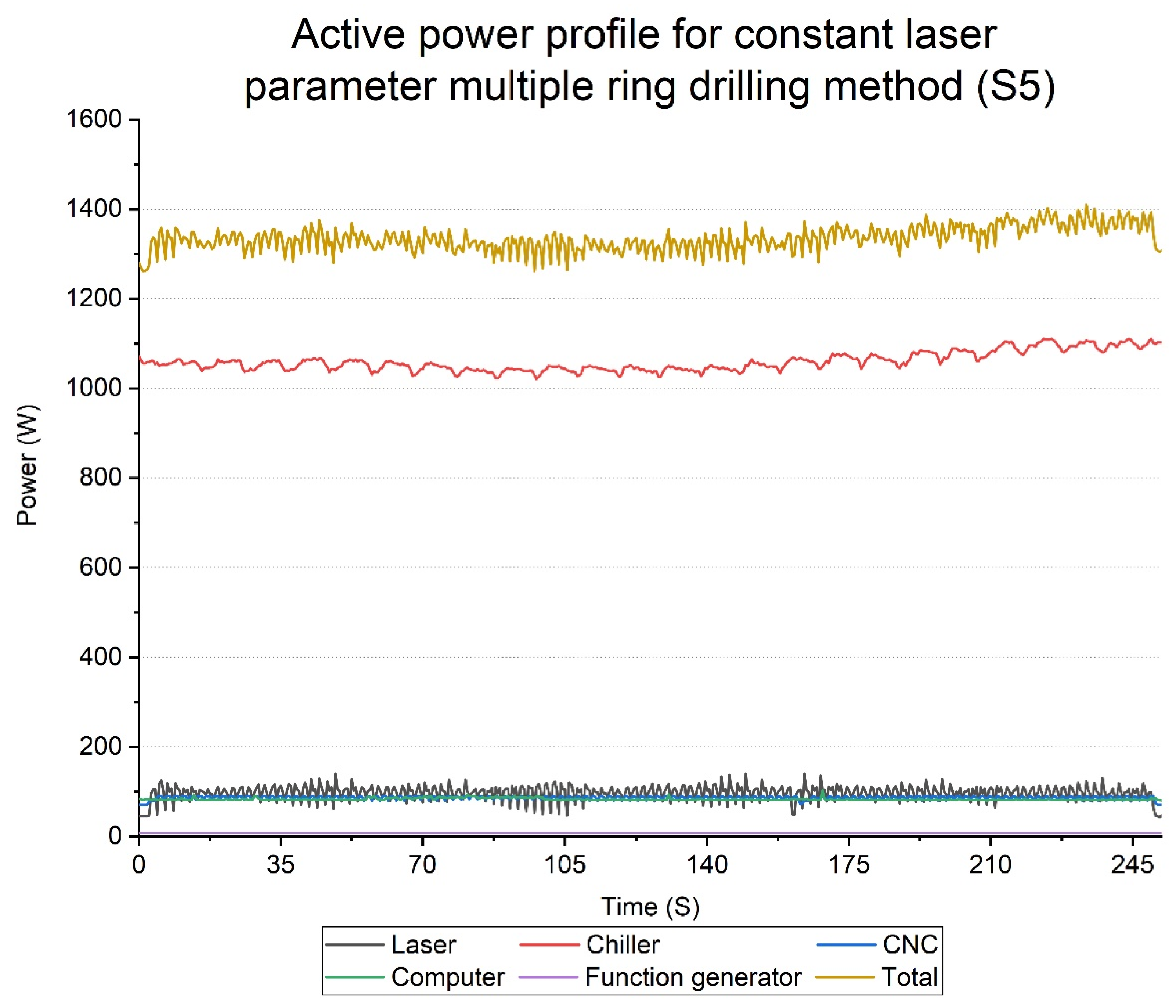
| Total energy consumption (J) | 72,547.00 | 331,223.00 | 78.10% |
| Specific energy consumption for removing 1 kg CFRP (J/kg) | 3.82 × 10⁹ | 1.75 × 10¹⁰ | 78.17% |
| Carbon emission (gCO2) | 5.15 | 23.52 | 78.10% |
Publisher’s Note: MDPI stays neutral with regard to jurisdictional claims in published maps and institutional affiliations. |
© 2022 by the authors. Licensee MDPI, Basel, Switzerland. This article is an open access article distributed under the terms and conditions of the Creative Commons Attribution (CC BY) license (https://creativecommons.org/licenses/by/4.0/).
Share and Cite
Zhu, M.; Wei, C.; Guo, W.; Zhang, Z.; Ouyang, J.; Mativenga, P.; Li, L. Significant Reduction in Energy Consumption and Carbon Emission While Improving Productivity in Laser Drilling of CFRP Sheets with a Novel Stepped Process Parameter Parallel Ring Method. J. Manuf. Mater. Process. 2022, 6, 7. https://doi.org/10.3390/jmmp6010007
Zhu M, Wei C, Guo W, Zhang Z, Ouyang J, Mativenga P, Li L. Significant Reduction in Energy Consumption and Carbon Emission While Improving Productivity in Laser Drilling of CFRP Sheets with a Novel Stepped Process Parameter Parallel Ring Method. Journal of Manufacturing and Materials Processing. 2022; 6(1):7. https://doi.org/10.3390/jmmp6010007
Chicago/Turabian StyleZhu, Menghui, Chao Wei, Wei Guo, Zhizhou Zhang, Jinglei Ouyang, Paul Mativenga, and Lin Li. 2022. "Significant Reduction in Energy Consumption and Carbon Emission While Improving Productivity in Laser Drilling of CFRP Sheets with a Novel Stepped Process Parameter Parallel Ring Method" Journal of Manufacturing and Materials Processing 6, no. 1: 7. https://doi.org/10.3390/jmmp6010007
APA StyleZhu, M., Wei, C., Guo, W., Zhang, Z., Ouyang, J., Mativenga, P., & Li, L. (2022). Significant Reduction in Energy Consumption and Carbon Emission While Improving Productivity in Laser Drilling of CFRP Sheets with a Novel Stepped Process Parameter Parallel Ring Method. Journal of Manufacturing and Materials Processing, 6(1), 7. https://doi.org/10.3390/jmmp6010007