Article

Selective Laser Sintering Induced Residual Stresses: Precision Measurement and Prediction

1
School of Aerospace, Transport and Manufacturing, Cranfield University, Cranfield MK43 0AL, UK
2
School of Engineering, Indian Institute of Technology Mandi, Mandi 175005, India
*
Author to whom correspondence should be addressed.
J. Manuf. Mater. Process. 2021, 5(3), 101; https://doi.org/10.3390/jmmp5030101
Submission received: 5 August 2021 / Revised: 14 September 2021 / Accepted: 15 September 2021 / Published: 18 September 2021
(This article belongs to the Special Issue Advances in Micro and Nanomanufacturing)

Abstract

:
Additive Manufacturing presents unique advantages over traditional manufacturing processes and has the potential to accelerate technical advancement across multiple sectors, permitting far greater freedom in design than conventional manufacturing. However, one barrier which blocks wide adoption is residual stresses, which could seriously affect the materials’ behaviour during and after production. Selective laser sintering (SLS), a process with high energy input to the workpiece material, induces high temperature gradients, further affecting the final residual stress distribution. Within the present paper, three different methods for the assessment of the residual stresses’ distribution are presented and compared: a non-destructive method based on neutron diffraction, a destructive method known as the contour method, and a theoretical approach based on Finite Element Analysis. The aim is to examine the suitability and reliability of the application of these methods in predicting residual stresses distribution in additive manufacturing-built parts.

1. Introduction

Additive Manufacturing (AM) presents unique advantages over traditional manufacturing processes and has the potential to accelerate technical advancement across multiple sectors, permitting far greater freedom in design [1,2,3] than conventional manufacturing. High end manufacturers seek to use these revolutionary AM processes to build their products intending to save money and resources. However, one barrier which blocks wide adoption of the technique is unfavourable residual stresses, which could seriously affect the materials’ behaviour during and after production [4,5]. This unpredictability costs industry millions of pounds in time and materials due to the slow and iterative approach needed to design and build parts. It is therefore necessary to predict and determine the distribution of residual stresses in AM built parts, especially when required in high-reliability areas, to have the residual stresses under control. Although research has been reported in simulating the processes for predicting the residual stresses profiles [1,2,6], the precise and accurate measurement of such residual stresses profiles has still not been thoroughly investigated.
The aim of this paper is to examine the suitability and reliability of the application of neutron diffraction in measuring residual stresses distribution in AM built parts. Furthermore, the most significant factors which could affect residual stresses distribution are determined. The residual stresses of a sample prepared with selective laser sintering from 316 stainless steel were measured with two different methods: a non-destructive method using neutron diffraction and a destructive one, known as the contour method. Finally, a simple Finite Element Analysis (FEA) model was built to interpret residual stress evolution during and after the AM process.

2. Literature Review

Residual stress is classified as the stress that persists in a material at equilibrium with the environment following manufacturing operations [7]. These stresses can be quite damaging to the strength of a product [8]. Conversely, in certain situations, desirable residual stress is purposely applied [9]. Residual stress may add to, or detract from, the applied stress; thus, when a failure occurs, it may be because the residual stress is dramatically coupled with the applied stress, or because, along with the occurrence of unobserved defects, the applied stress under which the failure occurs is greatly reduced [10]. Throughout the manufacturing of any product, residual stresses must be considered for reasonable and reliable estimates of the characteristics and for determining the product’s life [11]. In addition, concerning additive manufactured products, whilst residual stresses can be removed by post-process heat treatment, significant residual stress accumulation can contribute to severe distortion, which may lead to manufacturing failure [12]. It is therefore important to consider the residual stress in the materials processes and products and understand the generation mechanisms.
Residual stresses are generally defined by the size at which they function [7,9]. Type I residual stresses are macro-stresses generated in multiple grains, and a shift in the residual stress equilibrium of type I would result in a reduction in the macroscopic properties. Indeed, any manufacturing procedure or method that induces an inhomogeneous spread of strains creates type I residual stresses. Type II residual stresses are the micro-stresses generated in single grains, and are generally seen in martensitic steel formation. The concentration of martensite becomes greater than that of austenite during processing, and this disparity results in type II residual stress. Type III residual stresses occur at the sub-micro level, typically across several atomic distances. Crystalline defects, such as dislocations or vacancies, result in type III residual stress formation. Type I residual stress is usually addressed in research with respect to AM parts and is thus the only form mentioned in the remainder of this study.
Bartlett and Li [12] discuss a simple case to describe the mechanism of residual stress generation. Consider a part in which all the layers of material are melted instantly: the part then undergoes uniform cooling in the Z-direction. Once a new layer is introduced and heated well above the temperature of the preceding layer, the new layer undergoes a uniform expansion. This expansion is constrained by a substantially cooler underlying layer, which results in compressive and tensile stress generation in the new and the underlying layer, respectively. When the heat source is withdrawn, the new layer cools rapidly, expanding at a greater rate than the cooled part below can tolerate, resulting in tensile stress in the new layer and compressive stress in the lower part.
Mercelis and Kruth [13] discuss the mechanism of residual stress in selective laser sintering and consider that the new layers are neither instantly nor evenly heated. Thus, stress generation and distribution are more complex. They identified two mechanisms that lead to the generation of residual stresses in any AM process. The first one is from the significant thermal gradient around the laser spot. Due to a high heat input on the top layer and relatively low heat conduction beneath, a large thermal gradient appears, and thus the expansion of the top layers is much bigger than the bottom ones and elastic compressive strains are generated. According to a typical stress-strain curve, when the yield strength is reached, plastic strains are induced. After cooling and shrinking on the top layers, the elastic compressive strains tend to disappear whilst plastic ones remain, thus residual stresses are generated. The second mechanism works when the top layers are melted. The deformation is restricted by the layers beneath, thus tensile stresses are induced on the top and compressive stress below. The in-plane residual stresses are usually greater than the normal residual stress [14,15].
Since residual stresses significantly affect the performance of components and structures, various methods have been developed [16,17] and used to measure residual stresses. This is particularly the case for type I stress in structures, since these have the most significant effects on the mechanical properties of a structure. There are two main techniques identified in literature to measure the residual stresses in selective laser sintered parts, namely, (a) distortion-based (destructive) and, (b) diffraction methods (non-destructive). It is important to understand the underlying principles of the destructive measurement techniques. Residual stress in a material remains at static equilibrium, and thus the cumulative amount of stress normal to the plane must be zero for every cut plane in the material. When sections with intrinsic residual stress are removed, the new surface must deform to reallocate the stress in such a way that the net stress at the surface becomes zero, such that the part stays in a static equilibrium. Surface deformation to allow stress redistribution is measured and is input into analytical models to approximate the original stress of the part. For these measurements, the precision of the residual stress calculation is implicitly dependent on the precision of the deformation measurements. There are two such methods identified and used in the literature, namely, the hole-drilling method [18,19] and the contour method [20,21]. The difference between these two methods is that, in some cases, when semi-destructive methods, such as hole-drilling, are applied, the specimens are still usable.
In the contour method, the stresses are measured over a cross section but in one direction only [22]. The basic principle of this technique relies on cutting the sample along a straight line, thus the stresses that are normal to the newly generated surface will be released and deformation appears. Measuring the deformation and feeding in the results as boundary conditions into an elastic finite element model, which allows determination of the initial residual stress released by the cutting. Normally wire electric discharge machining (EDM) is used for the sectioning since it has high accuracy, and no plastic deformation is induced when the cutting operation is performed properly. Measurements can be made either by using a laser scanner [20,23], a coordinate measuring machine [21,24] or using digital image correlation [25].
In comparison, non-destructive diffraction methods function on a different concept. Two main diffraction methods are discussed in the literature, namely, neutron diffraction [26,27] and X-ray diffraction (XRD) [28,29,30]. X-ray diffraction uses X-rays as probes for residual stress measurement. Due to a low penetration ability, only a thin layer (normally tens of micrometres) on the surface can be measured. The neutron diffraction method is very similar to the X-ray diffraction method, but with a larger penetration depth (up to 10 cm). Oliver et al. [31] applied neutron diffraction for studying stress induced structure transformation in Fe–Pd alloys, and Paradowska et al. [32] applied this technique to study the residual stress generated in welding processes.

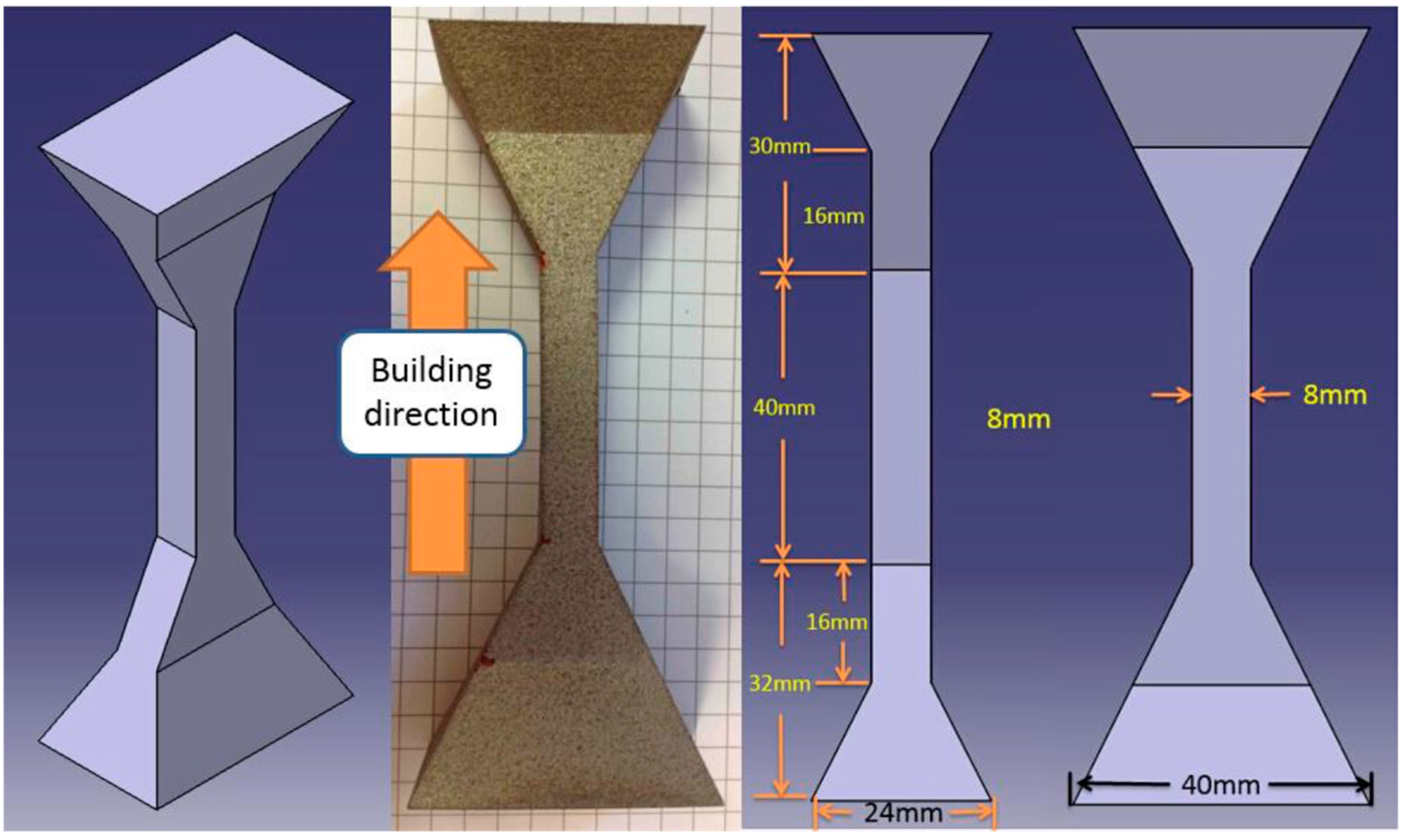
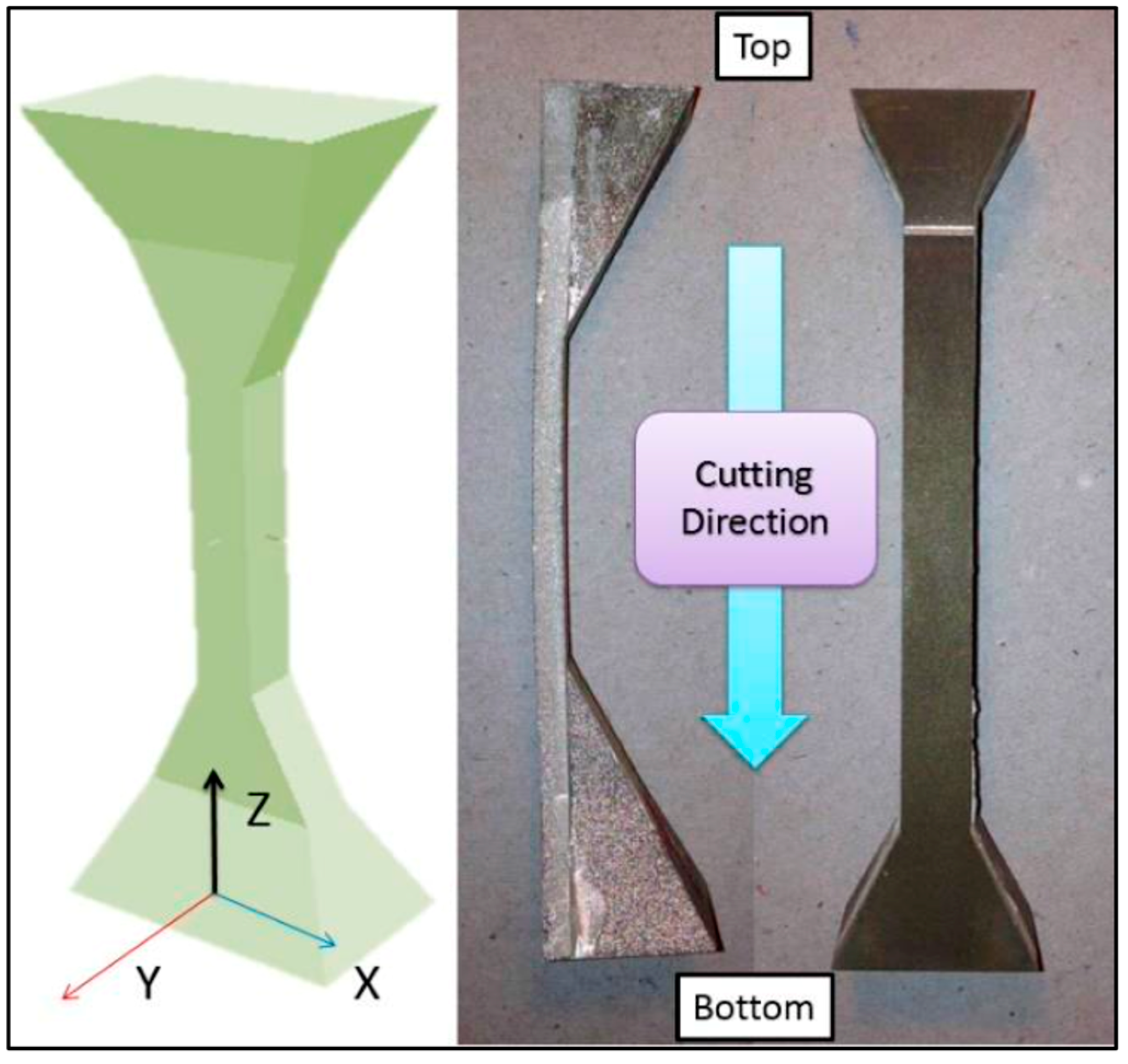
3. Materials and Methods

A test peg was built with a selective laser sintering (SLS) technique from 316 stainless steel, and then cut from the base plate with wire EDM. The sample geometry is shown in Figure 1. The geometry of the test peg was selected for its ease of building, its easy manipulation and fixing during the residual stresses measurement as well as to maximize the impact of the heat input on residual stresses and deformations. Gas atomized 316 L stainless steel powder with the average diameter of ~30 μm (particle size distribution of 15–45 μm) was used for preparing the specimen. The chemical composition of 316 L stainless steel powder is presented in Table 1. The experimental setup is presented in Table 2. The scanning strategy for the specimen was the zigzag scan mode, rotating 90° every two layers.

4. Residual Stresses Measurement

Residual stresses were measured with two different methods, using neutron diffraction and the contour method. The former is a non-destructive method whereas the latter is a destructive one. The following paragraphs will present in detail the measurement approach as well as the results.

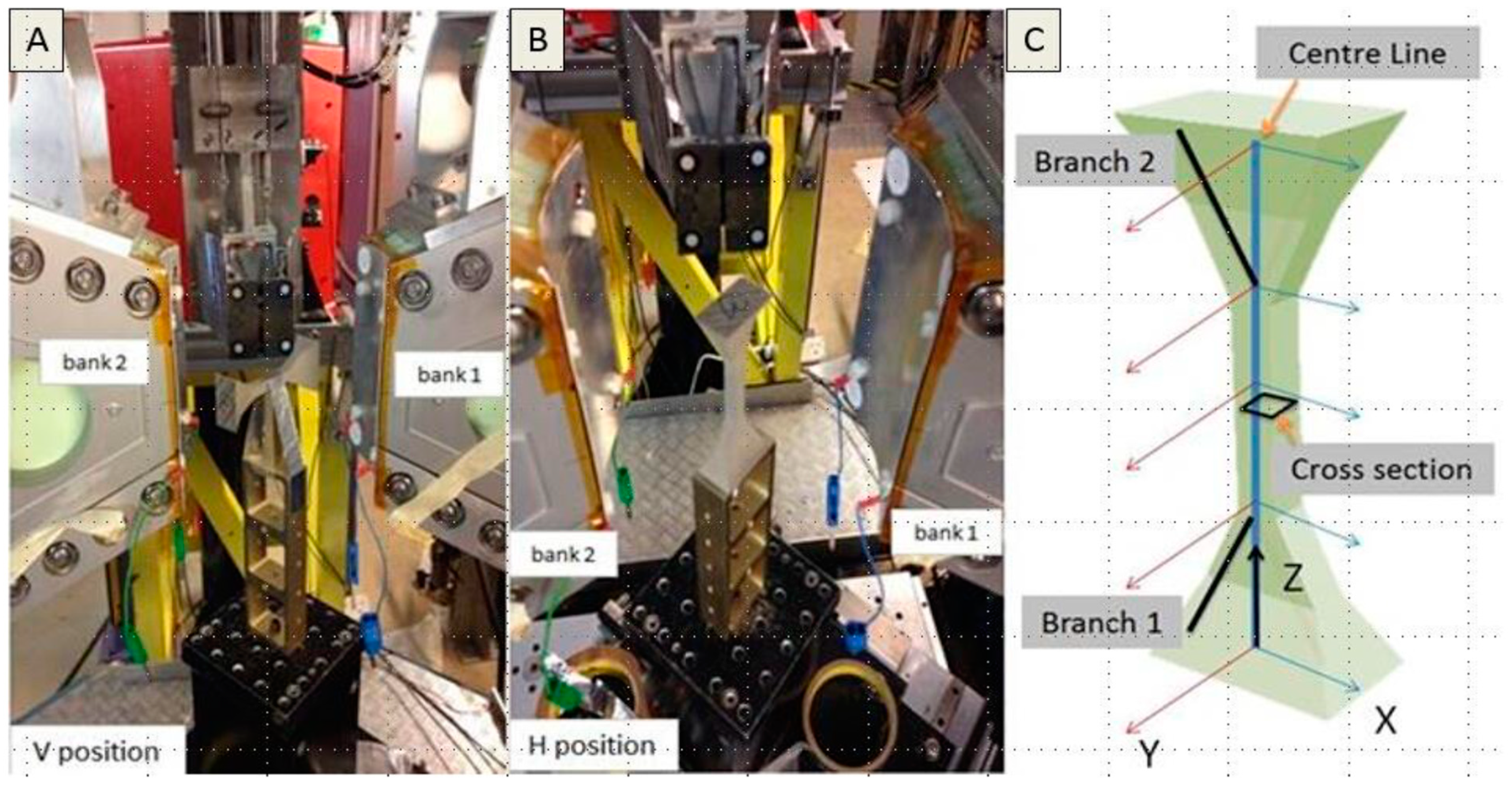
4.1. Non-Destructive Approach: Neutron Diffraction

Neutron diffraction is a widely used technique for measuring residual stresses deep within a material by detecting the diffraction of an incident neutron beam [33,34]. ENGIN-X, a dedicated neutron source engineering science facility at ISIS, Oxfordshire, is optimised for the measurement of strain, and thus stress, deep within a crystalline material, using atomic lattice planes as an atomic ‘strain gauge’; based on a time-of-flight (TOF) technique. In the TOF technique [35], the travelling time of neutrons between moderator and detector is recorded and generates a full diffraction spectrum. The strain can be determined by analysing individual peaks or the entire spectrum with Rietveld refinement [36]. The sample was placed on a positioning table with three orthogonal translation axes and a vertical rotation axis. Incident neutron beams from the moderator pass through a slit and are then diffracted by the sample, where only a fraction of diffracted neutrons can pass through the collimator and reach the detectors (Bank 1 and Bank 2). In ENGINE-X, slits together with collimator identify a small cubic volume called the gauge volume, which affects the resolution and experiment completion time. The data collection strategy and the experimental setup is illustrated in Figure 2. For each data point on the defined path, a TOF spectra is recorded by one detector. The spectrum afterwards is processed with Rietveld refinement indicating how well the measured data can match the reference data. Based on this analysis, a lattice parameter “A” can be estimated for each unit cell, allowing calculation of residual strains.
In Figure 3, residual strains along the centre line of the steel test peg are presented. Strains in the Z-direction are larger than those in other directions at the same positions; strain changes are associated with the change in cross section, and strains at the base near the base plate are much smaller than strains in the top of the sample.

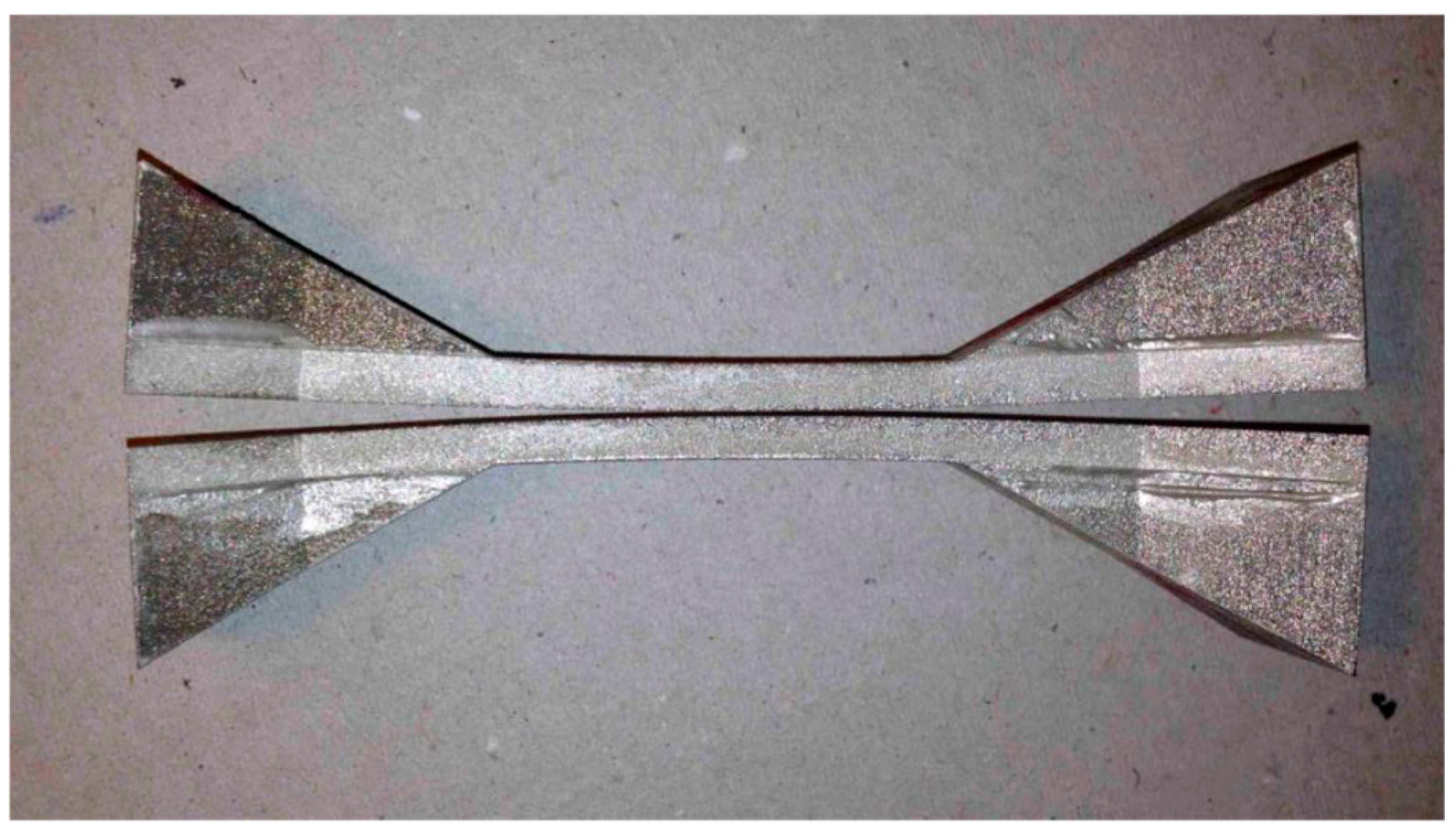
4.2. Destructive Approach: The Contour Method

The contour method is a relaxation method, and thus the test peg needs to be sectioned along the surface where the residual stresses are to be measured. The sample was cut from top to bottom in the YZ plane (Figure 4). The black surface caused by the material re-melting in wire EDM cutting, and the bright line on the surface was generated due to wire break.
In Figure 5, the stress distribution which corresponds to the normal stress in Z, X and Y directions in the sample’s coordinate system is shown. The stress maps show that residual stress in the top is bigger than the base, and that the stress distribution is regular where the geometry is simple.

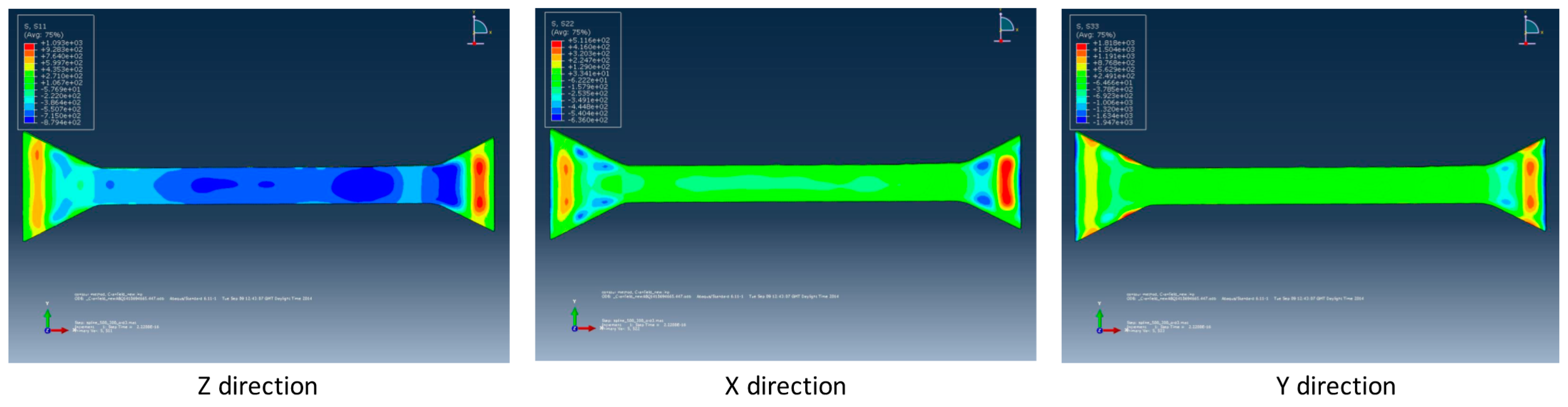
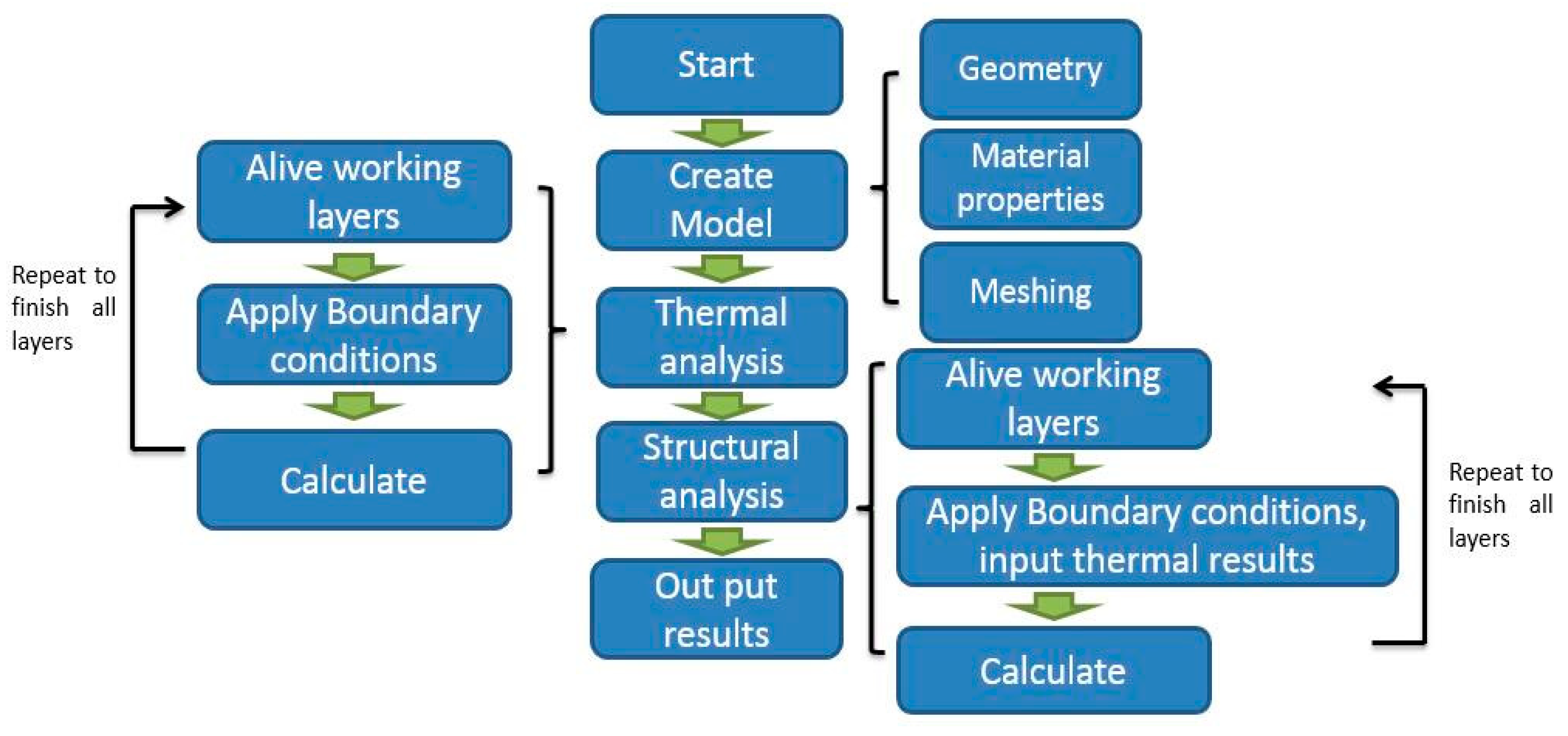
5. Prediction of Residual Stresses Using Finite Element Analysis

5.1. Modelling Approach

Finite element analysis (FEA) can be used for predicting residual stresses and structural distortions during and after the AM process. The objective of this work is to simulate the entire manufacturing process, which includes the building of layers, heat input and cooling. For the FEA solution, the model is considered coupled, solving initially the thermal problem and then through the coupling, solving the structural problem. The starting point is to calculate the resulting temperature field with the moving heat source and accumulation of molten material.
Assuming that the process is quasi-stationery, the temperature field can be determined as the solution of the following differential equation:
2 T x 2 + 2 T z 2 + u w a w T x = 0
where T is the temperature and aw the thermal diffusivity of the workpiece material. The boundary conditions that the solution should follow are defined by the heat source and the heat convection to the surrounding environment. For the solution of the differential equation, a FEA thermal model is developed. In this case, the heat transfer problem (Equation (1)) is described by the following equation:
[ C ( T ) ] { T ( t ) } + [ K ( T ) ] { T ( t ) } + { v } = { Q ( t ) }
where [K] is the conductivity matrix, [C] the specific heat matrix, {T} the vector of nodal temperatures, {T’} the vector of time derivative of {T}, {v} is the velocity vector, which is equal to zero as no mass transport is assumed in the current problem, and {Q} the nodal heat flow vector.
Subsequently, the residual stresses are estimated by entering the thermal results into the associated structural model. This is achieved by replacing the thermal elements with elastic–plastic elements attached to the same nodes. The resulting model undergoes a non-linear elastic–plastic structural analysis using temperature-dependent material properties and a multi-linear isotropic hardening model. The non-linear mechanical analysis problem is described by the following general finite element equation:
[ K ( T ) ] { u ( t ) } + { F ( t ) } + { F t h ( t ) } = 0
where [K(T)] is the temperature-dependent stiffness matrix, {F(t)} is the external load vector, {Fth(t)} is the temperature load vector and {u(T)} is the displacement vector.
For each load step, the nodal temperatures from the thermal analysis are read into the structural analysis. Nodal temperatures from thermal results continue to be read into the structural analysis until the time when the model temperature reaches ambient. The structural boundary conditions set to the workpiece are that all nodes at the bottom end of the workpiece are fixed in all directions. The non-linearity of material properties is considered through the von-Mises criterion, and plasticity is taken into consideration through a kinematic strain-hardening law.
For the problem solution, an element birth and death technique is used to simulate the accumulation of material. The modelling and simulation procedure is presented in Figure 6, like the approach proposed by Salonitis et al. [6]. Several assumptions were required for the process modelling, such as:
  • Material is considered homogeneous with isotropic properties.
  • New elements for adding material are considered as stress-free elements.
  • Residual stresses are generated due to temperature change, and no phase change during the process is considered.
  • Heat input is applied on the upper line/surface of each layer.
For simplicity, the model has 26 layers settled on a base plate. The material properties used in the model are presented in Table 3. The strain and stress distributions on specific paths corresponding to the results of the ENGIN-X neutron diffraction experiments are used. In addition to validating the model results with the experimental measurements, the FEA model was used for assessing a number of issues, such as the:
  • Impact of heat input to the residual stresses;
  • Importance of the base plate.
It was expected that due to the simplicity of having only 26 layers simulated, and thus the layer thickness used in the simulation is considerably thicker to the real layer thickness, the residual stresses predicted through the model cannot be of high accuracy. However, since the paper’s focus is not on the simulation model but rather on the comparison of the measurement techniques, the goal is to assess whether such a simplistic model can support this analysis by identifying the “hot-spots” and the relevant change of residual stresses along the geometry.

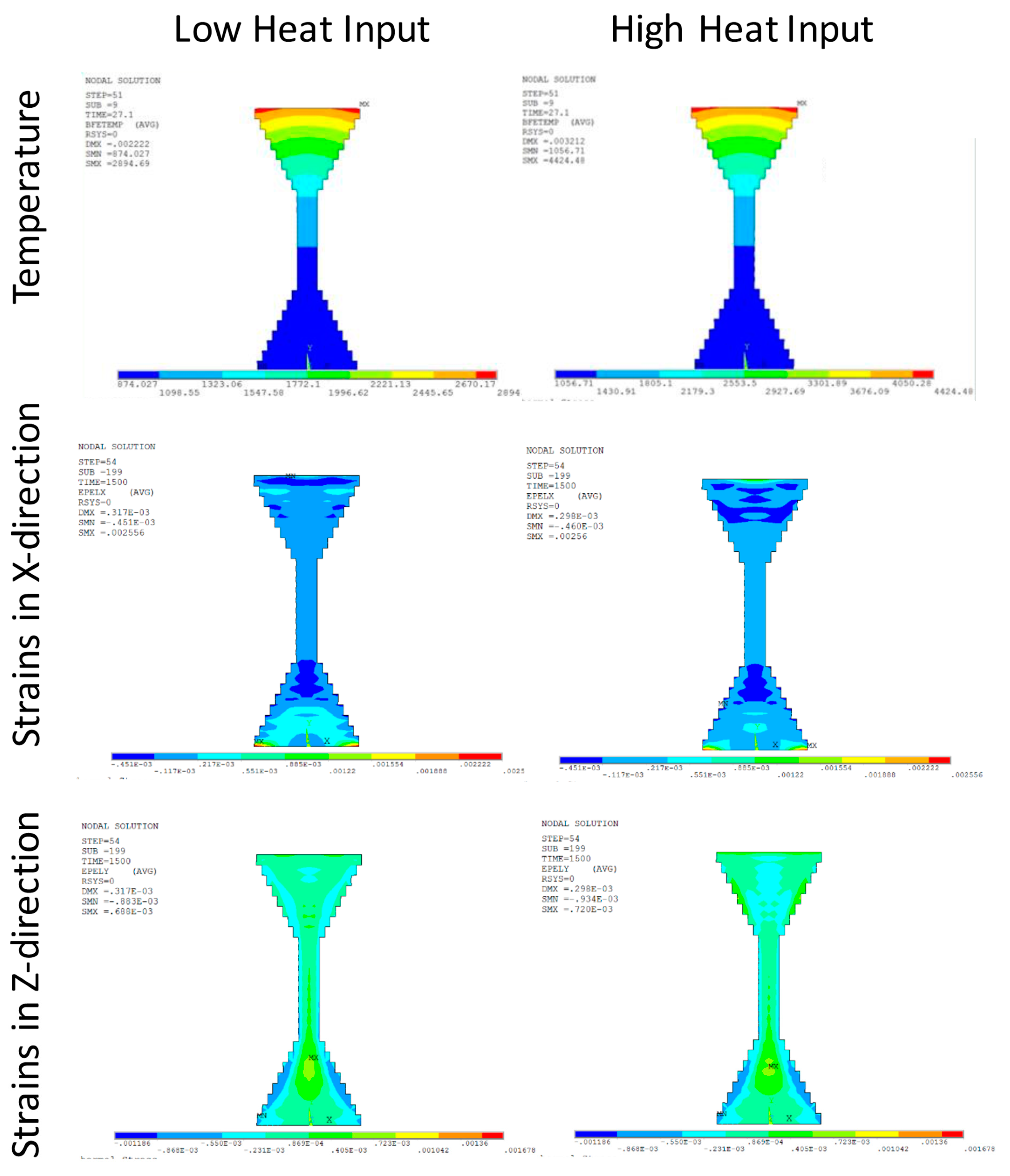
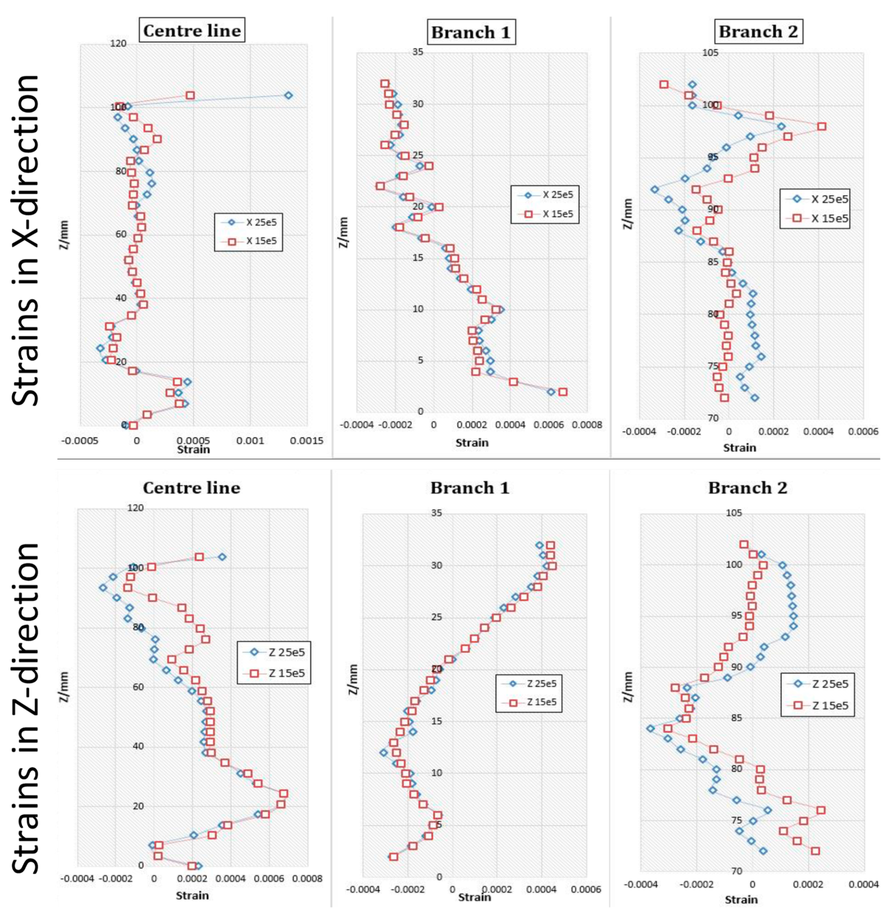
5.2. Heat Input Impact to Residual Stress

According to Ding et al. [37] the distortion and residual stresses in AM built parts are generated due to high power input, which is one of the few parameters that can be controlled in an AM process. The developed FEA model predicts similar behaviour. Two levels of heat input were used for the analysis (low 15.105 and high 25.105 W/m2). Figure 7 presents the corresponding temperature and strains predicted with the two heat inputs.
Figure 8 shows a comparison of strains with the high and low heat inputs; blue diamonds and red squares, respectively. In both X and Z directions, changes in heat input exhibit a minor effect on the base of the test peg. A relatively large influence is found at the top, which indicates that, in this case, heat input will mainly affect the strain distribution in parts near the top. This could be attributed to the heat transfer mechanism; heat is convected faster when machining parts near the base due to the higher heat conduction of the base plate. Conversely, heat will accumulate in the top and generate a heat gradient with a relatively smaller heat conduction.
For strains on branch 1 (at base) in both X and Z directions, there is almost no difference when changing heat input. When the heat input increases, strains near the top of branch 2 (at top) increase whilst strains at a lower position decrease. In the Z-direction, this trend is reversed. In this case, higher heat input contributes to a close strain distribution.

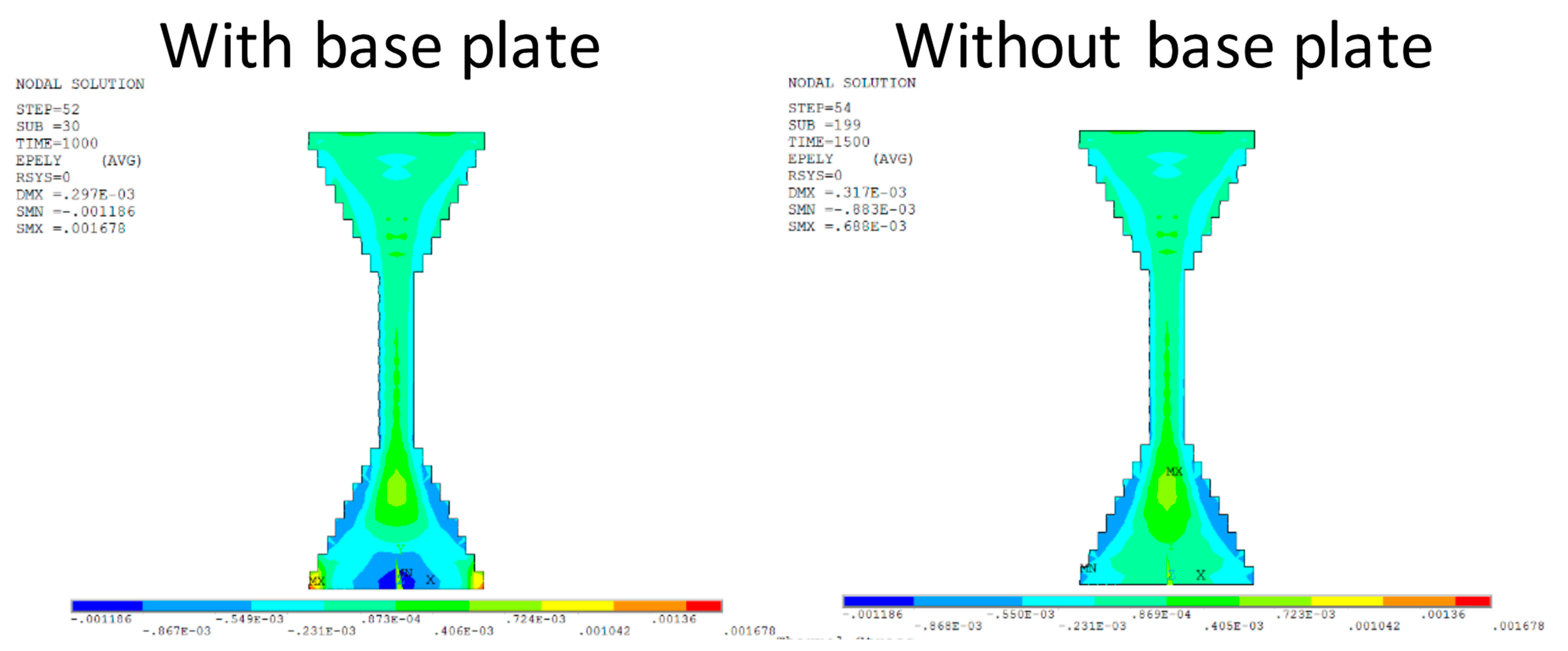
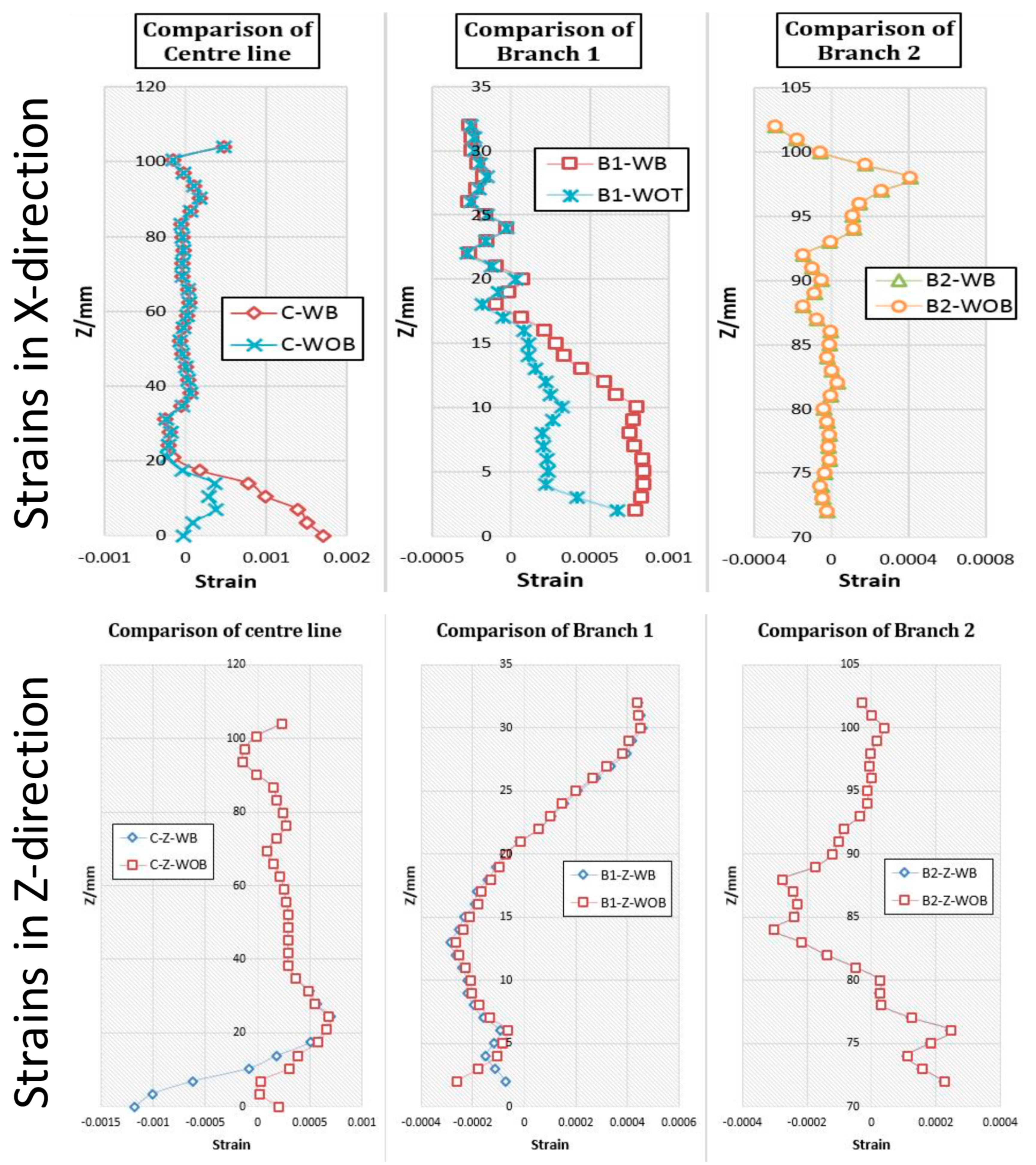
5.3. Base Plate Impact to Residual Stresses

Mercelis and Kruth [13] note that the base plate has a big influence on stress distribution. Indeed, the thicker the base plate, the smaller the residual stress in AM built parts after they are cut from the base plate. The FEA model developed predicts similar behaviour as seen in Figure 9. There is an apparent strain release near the base in both X and Z directions with the base plate removed. Material away from the base plate is not affected significantly with regards to strain distribution. Relatively low strains are exhibited.
Since the part being built is relatively small, stresses in the whole component are released when removed from the base plate. Figure 10 shows the change of strain distribution in FEA model with (WB) and without the base plate (WOB) removed. Strains in the range Z = 0 to Z = 20 mm are partly removed in both X and Z directions, and the range is relatively small compared to the height of the sample, so the base plate mainly effects strain distribution near the base.

6. Discussion

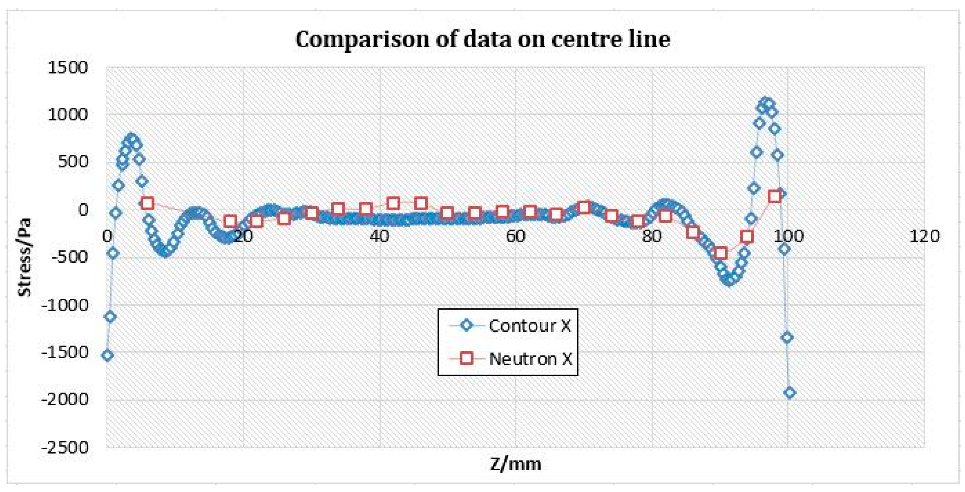
6.1. Comparison of Residual Stress Measurements

The neutro diffraction method provides a measurement of strains, whereas the contour method estimates stresses. For a comparison of the two methods, the measured strains are transformed to stresses. As the material properties for AM parts are not isotropic and cannot be confidently predicted, this might result in a difference in the absolute values, however, the trends should be expected to be similar.
Figure 11 shows the comparison of stress data in X-direction between the contour method and neutron diffraction. To a certain extent, the two sets of data fit each other well, the trend and absolute values are the same in a large range. However, neutron data do not have the range of detailed information at the two ends of the test peg, especially in the base. Deformation occurs after the sample is cut, which will reduce the reliability of the contour results (see Figure 12).

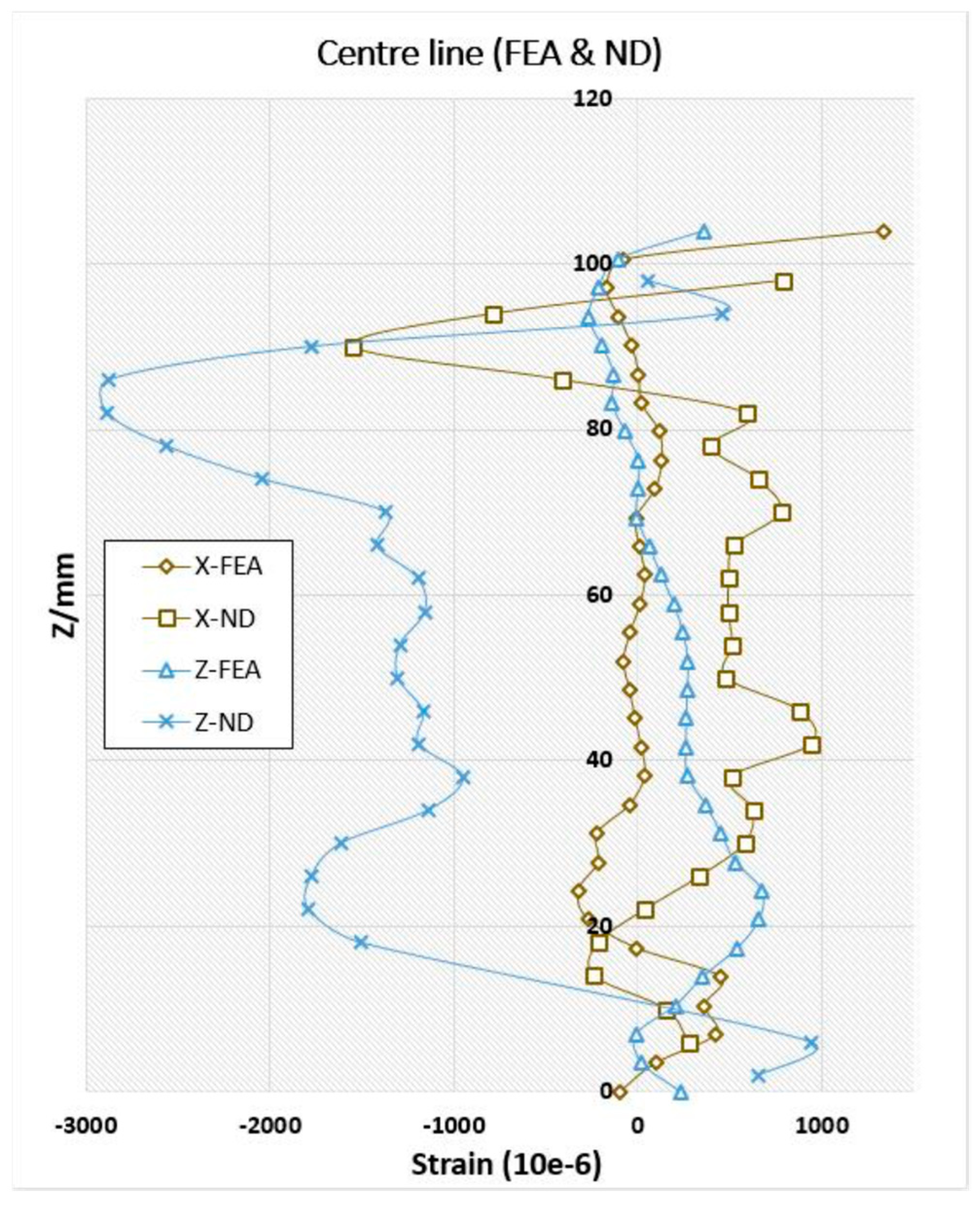
6.2. Validation of FEA Predictions with Neutron Diffraction Data

Figure 13 presents FEA model validation by comparing the predictions with neutron diffraction data. With regards to the X-direction, both FEA predictions and neutron diffraction measurements show two peaks towards the −X direction. One peak is visible at a height around Z = 20 mm, and the other around Z = 90~100 mm. The FEA and neutron diffraction measurements present similar trends. The difference in strains can be seriously affected by the process parameters selected during the building of the part.
With regards to the Z-direction, similar conclusions to the X-direction results can be drawn; although the trends are similar, the actual strains show higher difference, which can be attributed to the simplicity of the FEA model.
With regards to the FEA modelling, it is suggested that further studies on a range of standard test pegs might be fruitful to critique and compare AM processing factors and relate these to a range of components.

7. Conclusions

Additive Manufacturing (AM) presents unique advantages over traditional manufacturing processes and shows good repeatability, but residual stresses are generated in manufacturing processes, so post-treatments are required to release residual stresses.
Neutron diffraction is a good choice to measure residual stress in AM parts, as it can penetrate deep into components without any destruction. The contour method is another good technique which can map residual stress on the whole surface. Apart from these experimental methods, FEA modelling shows its advantages in analysing components both during and after the manufacturing process. The modelling results in this project demonstrate the reliability of a simplified FEA model in investigating the impact of AM manufacturing processes. Future work will focus on developing a more detailed FEA model, with a number of layers reflecting their actual number in the test parts in order to investigate whether a higher accuracy model can lead to significantly improved predictions.
Two main factors that affect residual stress distribution were investigated using FEA modelling. Heat input mainly affects the top of the part, whilst larger heat inputs lead to larger strains in top part. The base plate mainly affects the base of the part, whilst strains in the base can be partly released after removing base plate, and the thicker the base plate, the smaller the residual stress.
Other issues are identified: It is difficult to transfer strain into stress in AM built parts due to anisotropic material properties; in measuring large components with neutron diffraction, longer times are required for detailed data; in measuring small components, the with contour method, deformation appears when cutting with wire EDM and might need to be addressed in further studies.
This study has successfully demonstrated the suitability of neutron diffraction in measuring residual stress in AM built parts, and identified heat input as well as the effect of the base plate, which could significantly affect residual stresses in AM built parts using FEA modelling. Further critical analysis linking FEA modelling with studies on a range of standard test pegs might be fruitful to critique and compare AM processing factors and relate these to a range of components for greater understanding of residual stresses.

Author Contributions

Conceptualization, S.I. and K.S.; methodology, S.I. and K.S.; validation, S.I. and P.S.; formal analysis, S.I. and K.S.; resources, S.I. and K.S.; writing—original draft preparation, P.S. and K.S.; writing—review and editing, S.I., P.S. and K.S.; supervision, S.I. and K.S. All authors have read and agreed to the published version of the manuscript.

Funding

This research received no external funding.

Data Availability Statement

Data is contained within the article.

Acknowledgments

The authors gratefully acknowledge the research opportunity with provision of the steel test peg from Mike Curtis-Rouse for neutron measurements with Joe Kelleher at ISIS and support using the contour method with Sanjooram Paddea at the Open University. Experimental work and FEA modelling by Zhengkai Xu during his MSc at Cranfield University.

Conflicts of Interest

The authors declare no conflict of interest.

References

  1. Salonitis, K. Design for additive manufacturing based on the axiomatic design method. Int. J. Adv. Manuf. Technol. 2016, 87, 989–996. [Google Scholar] [CrossRef]
  2. Bikas, H.; Lianos, A.K.; Stavropoulos, P. A design framework for additive manufacturing. Int. J. Adv. Manuf. Technol. 2019, 103, 3769–3783. [Google Scholar] [CrossRef] [Green Version]
  3. Sivarupan, T.; Balasubramani, N.; Saxena, P.; Nagarajan, D.; El Mansori, M.; Salonitis, K.; Jolly, M.; Dargusch, M.S. A review on the progress and challenges of binder jet 3D printing of sand moulds for advanced casting. Addit. Manuf. 2021, 40, 101889. [Google Scholar]
  4. Schoinochoritis, B.; Chantzis, D.; Salonitis, K. Simulation of metallic powder bed additive manufacturing processes with the finite element method: A critical review. Proc. IMechE Part B J. Eng. Manuf. 2017, 231, 96–117. [Google Scholar] [CrossRef]
  5. Bikas, H.; Stavropoulos, P.; Chryssolouris, G. Additive manufacturing methods and modelling approaches: A critical review. Int. J. Adv. Manuf. Technol. 2015, 83, 389–405. [Google Scholar] [CrossRef] [Green Version]
  6. Salonitis, K.; D’Alvise, L.; Schoinochoritis, B.; Chantzis, D. Additive manufacturing and post-processing simulation: Laser cladding followed by high speed machining. Int. J. Adv. Manuf. Technol. 2016, 85, 2401–2411. [Google Scholar] [CrossRef]
  7. Dieter, G.E.; Bacon, D. Mechanical Metallurgy; McGraw-Hill: New York, NY, USA, 1986; Volume 3. [Google Scholar]
  8. Lyu, D.; Hu, W.; Ren, B.; Pan, X.; Wu, C. Numerical Prediction of Residual Deformation and Failure for Powder Bed Fusion Additive Manufacturing of Metal Parts. J. Mech. 2020, 36, 623–636. [Google Scholar] [CrossRef]
  9. Withers, P.J.; Bhadeshia, H.K.D.H. Residual stress. Part 1—Measurement techniques. Mater. Sci. Technol. 2001, 17, 355–365. [Google Scholar] [CrossRef]
  10. Withers, P.J. Residual stress and its role in failure. Rep. Prog. Phys. 2007, 70, 2211–2264. [Google Scholar] [CrossRef] [Green Version]
  11. Duboeuf, F.; Lemaire, E.; Remouchamps, A.; Eekelen, T.V.; Chary, C.; François, M.; Vargalui, A.; Rodrigues, G. Integration of AM process in design cycle of metallic parts: Application to space components. In Proceedings of the 24th International Conference on Material Forming, Liège, Belgium, 14–16 April 2021. [Google Scholar] [CrossRef]
  12. Bartlett, J.L.; Li, X. An overview of residual stresses in metal powder bed fusion. Addit. Manuf. 2019, 27, 131–149. [Google Scholar] [CrossRef]
  13. Mercelis, P.; Kruth, J.-P. Residual stresses in selective laser sintering and selective laser melting. Rapid Prototyp. J. 2006, 12, 254–265. [Google Scholar] [CrossRef]
  14. Hussein, A.; Hao, L.; Yan, C.; Everson, R. Finite element simulation of the temperature and stress fields in single layers built without-support in selective laser melting. Mater. Des. 2013, 52, 638–647. [Google Scholar] [CrossRef]
  15. Li, C.; Liu, J.F.; Fang, X.Y.; Guo, Y.B. Efficient predictive model of part distortion and residual stress in selective laser melting. Addit. Manuf. 2017, 17, 157–168. [Google Scholar] [CrossRef]
  16. Xie, D.; Lv, F.; Liang, H.; Shen, L.; Tian, Z.; Zhao, J.; Song, Y.; Shuai, C. Towards a comprehensive understanding of distortion in additive manufacturing based on assumption of constraining force. Virtual Phys. Prototyp. 2021, 16, 1–13. [Google Scholar] [CrossRef]
  17. Cheng, L.; To, A. Part-scale build orientation optimization for minimizing residual stress and support volume for metal additive manufacturing: Theory and experimental validation. Comput. Aided Des. 2019, 113, 1–23. [Google Scholar] [CrossRef]
  18. Vangi, D. Residual Stress Evaluation by the Hole-Drilling Method with Off-Center Hole: An Extension of the Integral Method. J. Eng. Mater. Technol. 1997, 119, 79–85. [Google Scholar] [CrossRef]
  19. Flaman, M.T.; Manning, B.H. Determination of residual-stress variation with depth by the hole-drilling method. Exp. Mech. 1985, 25, 205–207. [Google Scholar] [CrossRef]
  20. Pagliaro, P.; Prime, M.B.; Swenson, H.; Zuccarello, B. Measuring Multiple Residual-Stress Components using the Contour Method and Multiple Cuts. Exp. Mech. 2010, 50, 187–194. [Google Scholar] [CrossRef]
  21. Prime, M.B. Cross-sectional mapping of residual stresses by measuring the surface contour after a cut. J. Eng. Mater. Technol. 2001, 123, 162–168. [Google Scholar] [CrossRef] [Green Version]
  22. Sun, J.; Hensel, J.; Köhler, M.; Dilger, K. Residual stress in wire and arc additively manufactured aluminum components. J. Manuf. Process. 2021, 65, 97–111. [Google Scholar] [CrossRef]
  23. Prime, M.B.; Sebring, R.J.; Edwards, J.M.; Hughes, D.J.; Webster, P.J. Laser surface-contouring and spline data-smoothing for residual stress measurement. Exp. Mech. 2004, 44, 176–184. [Google Scholar] [CrossRef]
  24. Zhang, Y.; Ganguly, S.; Edwards, L.; Fitzpatrick, M.E. Cross-sectional mapping of residual stresses in a VPPA weld using the contour method. Acta Mater. 2004, 52, 5225–5232. [Google Scholar] [CrossRef]
  25. Wu, A.S.; Brown, D.W.; Kumar, M.; Gallegos, G.F.; King, W.E. An Experimental Investigation into Additive Manufacturing-Induced Residual Stresses in 316L Stainless Steel. Metall. Mater. Trans. A 2014, 45, 6260–6270. [Google Scholar] [CrossRef]
  26. Allen, A.J.; Hutchings, M.T.; Windsor, C.G.; Andreani, C. Neutron diffraction methods for the study of residual stress fields. Adv. Phys. 1985, 34, 445–473. [Google Scholar] [CrossRef]
  27. Van Acker, K.; Root, J.; Van Houtte, P.; Aernoudt, E. Neutron diffraction measurement of the residual stress in the cementite and ferrite phases of cold-drawn steel wires. Acta Mater. 1996, 44, 4039–4049. [Google Scholar] [CrossRef]
  28. Anderoglu, O. Residual Stress Measurement Using X-ray Diffraction; Texas A&M University: College Station, TX, USA, 2005. [Google Scholar]
  29. Fitzpatrick, M.E.; Fry, A.T.; Holdway, P.; Kandil, F.A.; Shackleton, J.; Suominen, L. Determination of Residual Stresses by X-ray Diffraction, 2005. Available online: https://eprintspublications.npl.co.uk/2391/ (accessed on 10 August 2021).
  30. Prevey, P.S. X-ray diffraction residual stress techniques. ASM Int. ASM Handb. 1986, 10, 380–392. [Google Scholar]
  31. Oliver, E.C.; Mori, T.; Daymond, M.R.; Withers, P.J. Neutron diffraction study of stress-induced martensitic transformation and variant change in Fe–Pd. Acta Mater. 2003, 51, 6453–6464. [Google Scholar] [CrossRef]
  32. Paradowska, A.M.; Price, J.W.H.; Finlayson, T.R.; Lienert, U.; Ibrahim, R. Residual Stress Measurements of Welded Components Using Synchrotron and Neutron Diffraction; Argonne National Laboratory: Lemont, IL, USA, 2007.
  33. Goel, S.; Neikter, M.; Capek, J.; Polatidis, E.; Colliander, M.H.; Joshi, S.; Pederson, R. Residual stress determination by neutron diffraction in powder bed fusion-built Alloy 718: Influence of process parameters and post-treatment. Mater. Des. 2020, 195, 109045. [Google Scholar] [CrossRef]
  34. Pant, P.; Sjöström, S.; Simonsson, K.; Moverare, J.; Proper, S.; Hosseini, S.; Luzin, V.; Peng, R. A Simplified Layer-by-Layer Model for Prediction of Residual Stress Distribution in Additively Manufactured Parts. Metals 2021, 11, 861. [Google Scholar] [CrossRef]
  35. Carpenter, K.; Tabei, A. On residual stress development, prevention, and compensation in metal additive manufacturing. Materials 2020, 13, 255. [Google Scholar] [CrossRef] [Green Version]
  36. Webster, G.A.; Wimpory, R.C. Non-destructive measurement of residual stress by neutron diffraction. J. Mater. Process. Technol. 2001, 117, 395–399. [Google Scholar] [CrossRef]
  37. Ding, J.; Colegrove, P.; Mehnen, J.; Ganguly, S.; Sequeira Almeida, P.M.; Wang, F.; Williams, S. Thermo-mechanical analysis of Wire and Arc Additive Layer Manufacturing process on large multi-layer parts. Comput. Mater. Sci. 2011, 50, 3315–3322. [Google Scholar] [CrossRef] [Green Version]
Figure 1. Sample geometry of the 316 L stainless steel test peg with dimensions.
Jmmp 05 00101 g001
Figure 2. (A) and (B) measurement setup of ENGIN-X and (C) data collection strategy from the steel test peg.
Jmmp 05 00101 g002
Figure 3. Neutron diffraction residual strains measured along the centre line of the sample.
Jmmp 05 00101 g003
Figure 4. Test peg preparation and cuts for the contour method.
Jmmp 05 00101 g004
Figure 5. Residual stress maps from the test peg based on the contour method.
Jmmp 05 00101 g005
Figure 6. Sequence of simulation analysis steps, commencing at Start.
Jmmp 05 00101 g006
Figure 7. Temperature and strain distribution predicted by FEA associated with two heat inputs.
Jmmp 05 00101 g007
Figure 8. Residual strains calculated through FEA.
Jmmp 05 00101 g008
Figure 9. Simulation results from the FEA model, with and without the base plate.
Jmmp 05 00101 g009
Figure 10. FEA simulation of strain distribution with base (WB) and without the base (WOB).
Jmmp 05 00101 g010
Figure 11. Comparison of residual stress measurements with the contour method (blue) and neutron diffraction (red).
Jmmp 05 00101 g011
Figure 12. Deformation of the sample after cutting.
Jmmp 05 00101 g012
Figure 13. Comparison of the predicted strains from the FEA model with neutron diffraction (ND) by way of model validation in the X and Z directions.
Jmmp 05 00101 g013
Table 1. Chemical composition of 316 L stainless steel powder.
ElementCrNiMoMnSi
wt%16.0–18.010.0–14.02.0–3.02.0 max1.0 max
ElementPSCFe
wt%0.04 max0.03 max0.03 maxBal
Table 2. Process parameters.
Process ParameterUnitsValue
Laser powerW180
Hatch spacingμm70
Laser beam diameterμm60
Powder layer thicknessμm40
Laser scan speedmm/s500
Table 3. Material properties used in the simulation model.
Material PropertyTemperature (°C)Value
Thermal conductivity (W/mK)2012.1
10014.3
50021.4
Specific heat (J/kgK)-449
Elastic modules (GPa)20195
200187
400172
600157
Poisson ratio (-)-0.27
Density (kg/m3)-7930
Thermal expansion (1 °C−1 × 10⁻⁶)2014.3
20015.6
40016.9
60017.7
Publisher’s Note: MDPI stays neutral with regard to jurisdictional claims in published maps and institutional affiliations.

