Article

Investigation of the Influence of Tool Rake Angles on Machining of Inconel 718

1
School of Mechanical Engineering, Tongji University, Shanghai 201804, China
2
Institute of Aerospace Technology, University of Nottingham, Nottingham NG7 2RD, UK
3
Division of Production and Materials Engineering, Lund University, Box 118, SE-221 00 Lund, Sweden
4
Faculty of Engineering, University of Nottingham, Nottingham NG7 2RD, UK
*
Authors to whom correspondence should be addressed.
J. Manuf. Mater. Process. 2021, 5(3), 100; https://doi.org/10.3390/jmmp5030100
Submission received: 20 July 2021 / Revised: 28 August 2021 / Accepted: 1 September 2021 / Published: 15 September 2021

Abstract

:
It is essential for superalloys (e.g., Inconel 718) to obtain an anticipated surface integrity after machining, especially for safety critical areas (e.g., aerospace). As one of the main characteristics for cutting tools, the rake angle has been recognized as a key factor that can significantly influence the machining process. Although there are large research interests and outcomes in the machining of nickel-based superalloys, most of them focus on the surface integrity and macroscale temperature observation, whereas the temperature distribution in the tool rake face is not clear. Thus, it is necessary to investigate the basic role of rake angles and the tool–workpiece interaction mechanism to determine the machining condition variations and surface integrity. In the present study, both experimental and numerical methods are employed to explore the cutting force, thermal distribution, and shear angles during the process and the metallurgy characteristics of the subsurface after machining, as well as the mechanical properties. The research has emphasized the importance of rake angles on both the cutting process and machined surface integrity, and has revealed the microscale temperature distribution in the tool rake face, which is believed to have a close relationship with the tool crater wear. In addition, it is clearly presented that the surface generated with positive rake angle tools generates the minimum subsurface deformation and less strain hardening on the workpiece.

1. Introduction

The performance of an aeroengine is tightly related to the innovation design and high strength materials used in the engine [1,2,3]. To achieve a more powerful engine and aircraft, high strength materials (e.g., nickel-based superalloy; Inconel 718) [4] are widely used in the practical application because of their excellent performance in extremely high temperature and pressure conditions. However, it is difficult to cut these materials into the required geometry with a satisfactory finish at low costs [5], simply because of its characteristics; Hiroo has presented the difficult properties of this kind of material and the mechanism [6]. Thus, it has been an attractive topic, since these kinds of materials have been developed and introduced into industries, and much research has been carried out to study the machinability of superalloys.
As the main component in the cutting process, the cutting tool performance has been treated as an important investigation target. The cutting process with different tool materials (e.g., CBN, solid carbide, coated or uncoated etc.) has been studied by exploring both the tool tip wear and reaction between workpiece and tool [7,8]. Apart from the employed cutting tool, the material itself shows a significantly different cutting performance even if using the same cutting inserts. For example, researchers have carried out many investigations on the machinability of aeroengine alloys (Inconel 718) because of their dominance of a typical engine [9]. Obviously, in the cutting process, a large amount of heat is generated, which damages the machine surface integrity and accelerates the tool wearing, thus the coolant method has also been referred in order to study the cutting process and influence on tool life [10].
In addition, surface integrity has become more critical, with the component quality requirement increasing and the appearance of a harsher working environment (higher temperature and pressure) [11,12]. Jawahir [13] and his colleagues gave an illustration on the development of surface integrity and state of art technology in materials processing, in which the evaluation method of surface integrity is described and composite materials are considered as well. In particular, Liao [14] presented the characteristics of the machined surface integrity of difficult-to-cut materials (mainly the superalloys; e.g., Inconel 718) regarding the microstructure, mechanical properties, and fatigue performance etc., while the detective techniques are explained in details. Zhou [15] studied the comparative surface integrity methods for AD730 and Inconel 718 superalloy in the high-speed turning processes; Tobias specifically studied the microstructure and microhardness in the drilling of Inconel 718 [16]. As there are many kinds of materials and every one of them has unique properties, it is difficult to study the cutting performance of them in a general view. For each kind of material and each combination of cutting parameters, the cutting force, chip morphology, surface integrity, etc., have to be investigated separately, which makes the investigation of the machinability of materials become an extensive work.
At the same time, numerical methods have been found as a powerful tool to reduce the experimental times when investigating the cutting process. Many researchers have employed the simulation methods to study the cutting forces [17], residual stress [18], temperature distribution [19], chip shapes [20], etc. In the investigation of this aspect, part of the research focused on the simulation method itself, e.g., mesh methods and the boundary definition [21,22]; the other part is to analyze the cutting process and variables that could not be directly observed or acquired from the experimental investigation, e.g., the materials deformation process and residual stress evolution [23,24]; while there are also studies trying to build the model for the cutting process that cannot be implemented in the experimental scenarios, e.g., massive cutting tests. In summary, the simulation has also become an attractive method to study the cutting process and can provide the information that cannot easily be acquired from experiments; however, for now, it is still working as a supplementary for practical experimental investigations.
Up to now, many of the studies have focused on a combination of massive cutting parameters or aspects of the cutting process. Although it did provide abundant resources and information for academic and industrial sectors, it also introduced confusion and contradictions when readers were flooded by the above information. In fact, for the cutting process, it is the interaction between the cutting tool and target materials that determines the cutting performance and, in this process, the cutting force and cutting temperature are the most important aspects that will not only influence the cutting tool wear but also the machined surface integrity. Although there are many kinds of target materials, tool materials, and cutting parameter combinations, most of the cutting phenomenon occurred in the cutting process could be simplified to orthogonal cutting with defined tool geometry. In this simplified situation, the cutting mechanism variation is more related to the changing of tool geometry when the other cutting parameters are kept constant. It is well known that, in the orthogonal cutting process, all of the cutting tools could be classified as negative, neutral (0°), and positive, and that normally the cutting mechanism will have an obvious variation when transitioning among these three kinds of cutting conditions. Thus, it will be more efficient and quicker to have an overview understanding of the material removal mechanism by studying the influence of the tool rake on the machining process.
In the present research, an investigation of the influence of tool rake angles on the machining of Inconel 718 is proposed in order to specifically study the cutting mechanism or phenomenon variation between the cutting tool geometry transformations. It investigates the thermal field distribution along the rake face of the cutting tool and fundamentally explains the tool wear/failure mechanism (e.g., crater wear). Experiments with three representative kinds of tool inserts, including different rake angles, are implemented, and the cutting process is monitored by acquiring the cutting force and thermal distribution. A numerical method is also introduced to study the cutting process variation with the tool rake angle changing continuously. The good coherence between the experiment and simulation validates the accuracy of the numerical model and builds the foundation for the further studying of Inconel 718 machining. On the other hand, this paper studies the mechanical characterization of the subsurface areas and provides a reference for workpiece working performance investigation. Based on the analysis of the acquired experimental results, the cutting process changing caused by the tool rake angle could be clearly illustrated.

2. Materials and Methods

2.1. Materials Properties and Workpiece

All workpiece prepared with the same process for the orthogonal cutting tests (Figure 1) were machined on a CNC machine (SMT 500 CNC lathe). The main chemical composition, characteristics, and properties of employed nickel-based superalloy (Inconel 718) are presented in Table 1 and Table 2. Customized solid carbide cutting tool inserts with different geometry conditions are used in the implemented tests and part of the properties are shown in Table 2.

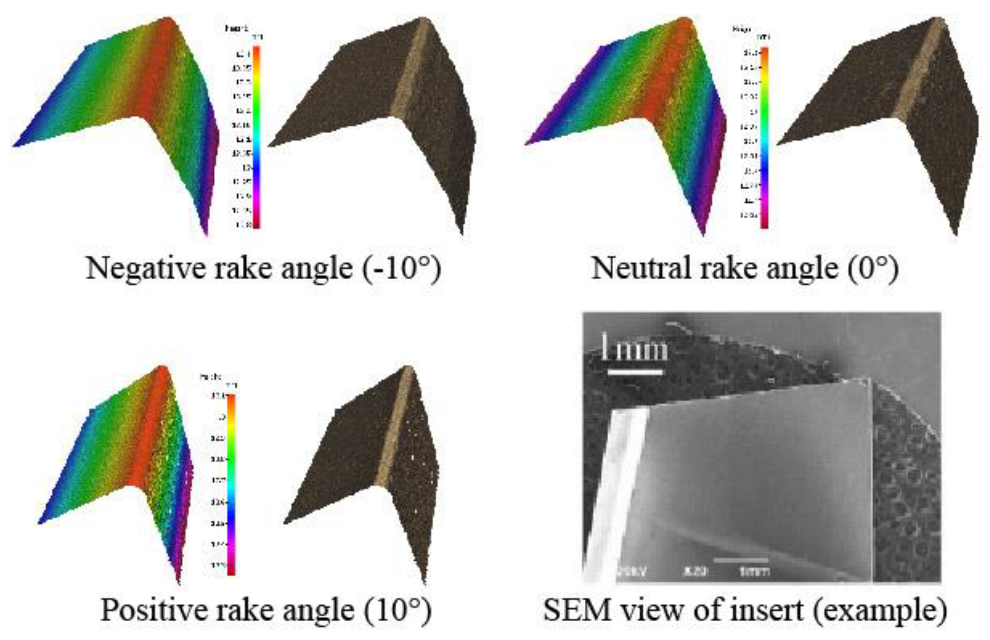
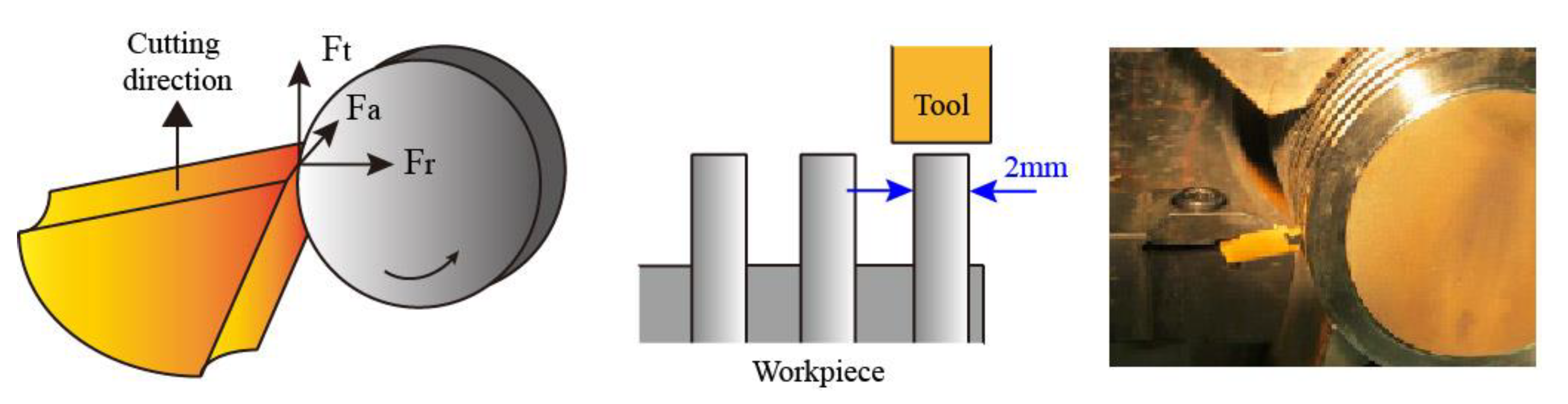
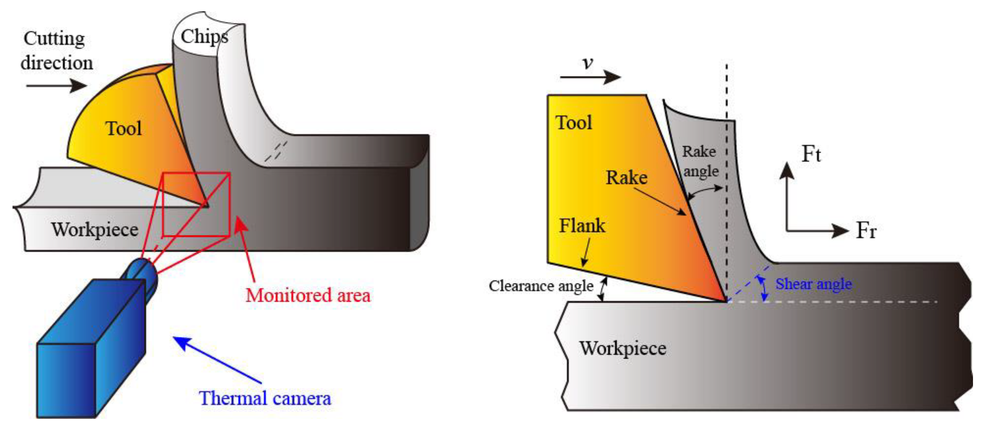
2.2. Experiment and Investigation Setup

Three kinds of cutting tools (rake angle: −10°, 0°, 10°; customized and provided by SECO tools) were utilized to machine the materials in order to study the cutting process with different rake angles, and the detail geometry of employed cutting inserts can be found in Table 3. Three-dimensional geometry of cutting edges, including tool radius, for the cutting tools were measured with Alicona (Figure 1) and a side SEM view example of the used insert is presented as well. Orthogonal cutting tests with arrangements as shown in Figure 2 were carried out following the experimental cutting parameters in Table 3. As seen, a 2 mm width slice was prepared on the cylinder workpiece with a cutting depth of 70 μm to avoid the same value level as radius (45 μm) in the cutting speed of 50 m/min.
An infrared thermal camera FLIR X6580sc (frame rates of 650 Hz) was used to monitor the cutting temperature during the cutting process (Figure 3) and the cutting forces were measured with the Kistler force dynamometer for analysis. The emissivity of Inconel 718 was determined to be 0.2 in this study [25], and the thermography during test was continuously recorded by an IR camera. SEM images in the subsurface area of machined workpiece were acquired to identify the influence from machining operation using a JEOL6490 scanning electron microscopy (SEM), and the nano-hardness profile in the subsurface areas were acquired with indenter experiments (Micro Materials Ltd.), while the loading and unloading history were captured as well for detail investigation.

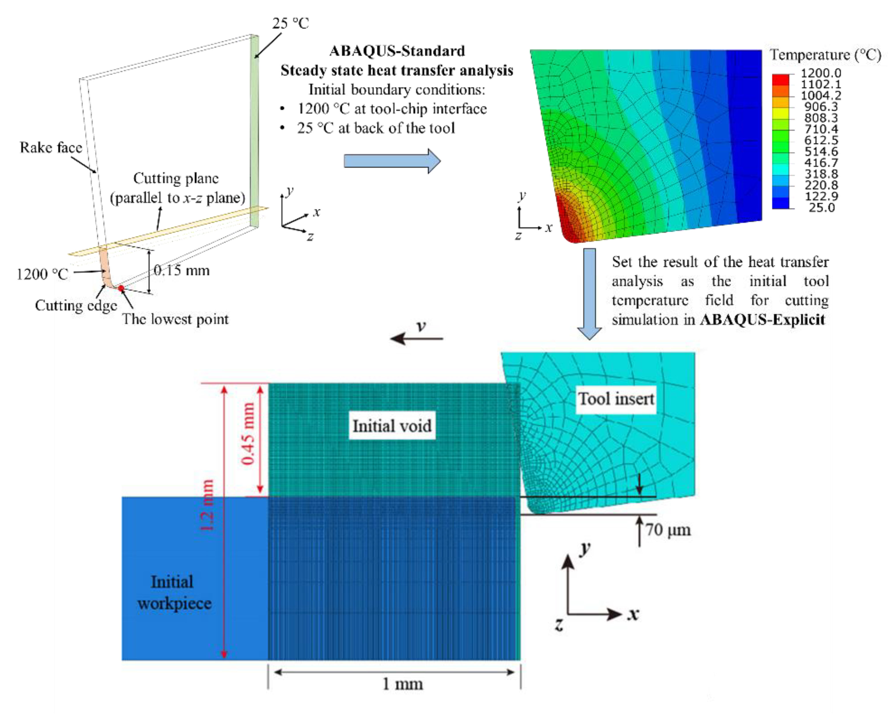
3. Numerical Prediction of Cutting Force and Temperature

A thermal–mechanical model of orthogonal cutting was developed based on ABAQUS/Explicit 6.14-2 using the technology of CEL [26] to replicate the experimental cutting process and study the aspects that cannot be directly acquired from the experiments. To achieve the steady-state thermal conditions at the tool–chip interface, the tool was heated prior to the cutting simulation. Specifically, a steady-state heat transfer analysis of the tool was first carried out in Abaqus/Standard to calculate the tool’s initial temperature distribution, followed by the metal cutting simulation, which was performed in Abaqus/Explicit with the CEL technique. The boundary conditions for the steady-state heat transfer analysis are shown in Figure 4. It was reported [27,28] that the measured tool side face temperature was 10–30% less than the mid-plane tool temperature. Therefore, the boundary conditions for the contact area of the tools were set to 900 °C, 950 °C, and 1200 °C for the rake angle of 10°, 0°, and −10°, respectively, according to the experimentally measured temperature distribution. In addition, the high temperature region included the tool edge and the bottom region of the rake face, and the height of this region was set to 0.15 mm for all of the simulated tools. The boundary condition of 25 °C was applied to the back face of the tool. The element type used in the tool in the heat transfer analysis was an 8-node linear heat transfer brick element (DC3D8). The Euler part was initially filled with a workpiece material in the crossed region of the two parts, whereas the rest of the Euler space, where the chip was formed, was regarded as void (initial void area). It has been reported [29] that the Euler space should be meshed into square elements in order to avoid the element orientation effect and that the mesh width has no influence on the results in a two-dimensional simulation. In the cutting simulation process, the mesh was refined to smaller square elements (5 μm) [29] in the area forming chips and near the machined surface in order to obtain a precise chip morphology and describe a better subsurface deformation performance. Only one element, with a width of 0.03 mm, was applied in the width of the model in order to have a tridimensional model as close as possible to a bidimensional one [26]. The element type used in the workpiece is an 8-node thermally coupled linear Eulerian brick element (EC3D8RT) and the element type used in the tool is an 8-node thermally coupled brick element (C3D8T). Generally speaking, three steps are implemented in the metal cutting simulation: first, simulate the cutting process; then, remove the tool from the contact with the workpiece; and finally, cool down the machined workpiece to room temperature.
The Johnson–Cook constitutive model, Johnson–Cook damage model, and Hillerborg’s fracture energy model were adopted to predict the flow stress and damage evolution of Inconel 718. The parameters of these models and the physical proprieties of the tool and workpiece were taken from [23,30]. The combination of the Coulomb’s and shear friction model was adopted to capture both the sticking and the sliding behavior at the tool–chip interface, as defined by
τf = min (μσn, τy)
where τf is the frictional stress, σn is the interface pressure, τy is the yield shear stress of the workpiece material, and μ is the friction coefficient that is defined as
μ = F t t a n γ + F r F t F r t a n γ
where Ft and Fr are, respectively, the mean cutting force and mean feed force that can be obtained in the experiment. The fraction of the heat converted from plastic deformation work in the cutting process was set to 0.9 and the heat generated by friction was considered to be totally absorbed by the material; thus, the percentage was set to 1.0. The thermal conductance between the tool and workpiece is the heat conduction through the tool–chip contact face from the chip with a higher temperature to the tool with a lower temperature during the cutting process. This conduction heat transfer is calculated as:
q = h(P)(TaTb)
where q is the heat flux per unit of area crossing the interface from point a on the workpiece to point b on the tool; Ta and Tb are the temperature of the points on the surfaces; h(P) is the heat conduction coefficient, and defined as a function of the pressure according to [5]. In the cutting process, the simulation time was too short to allow the convection heat transfer to occur, and, therefore, this heat transfer was often ignored. In the cooling down step, the convection heat transfer occured between different surfaces and the ambient. The convection coefficient was set to be 10 W/m 2 °C, according to the study [31].

4. Results

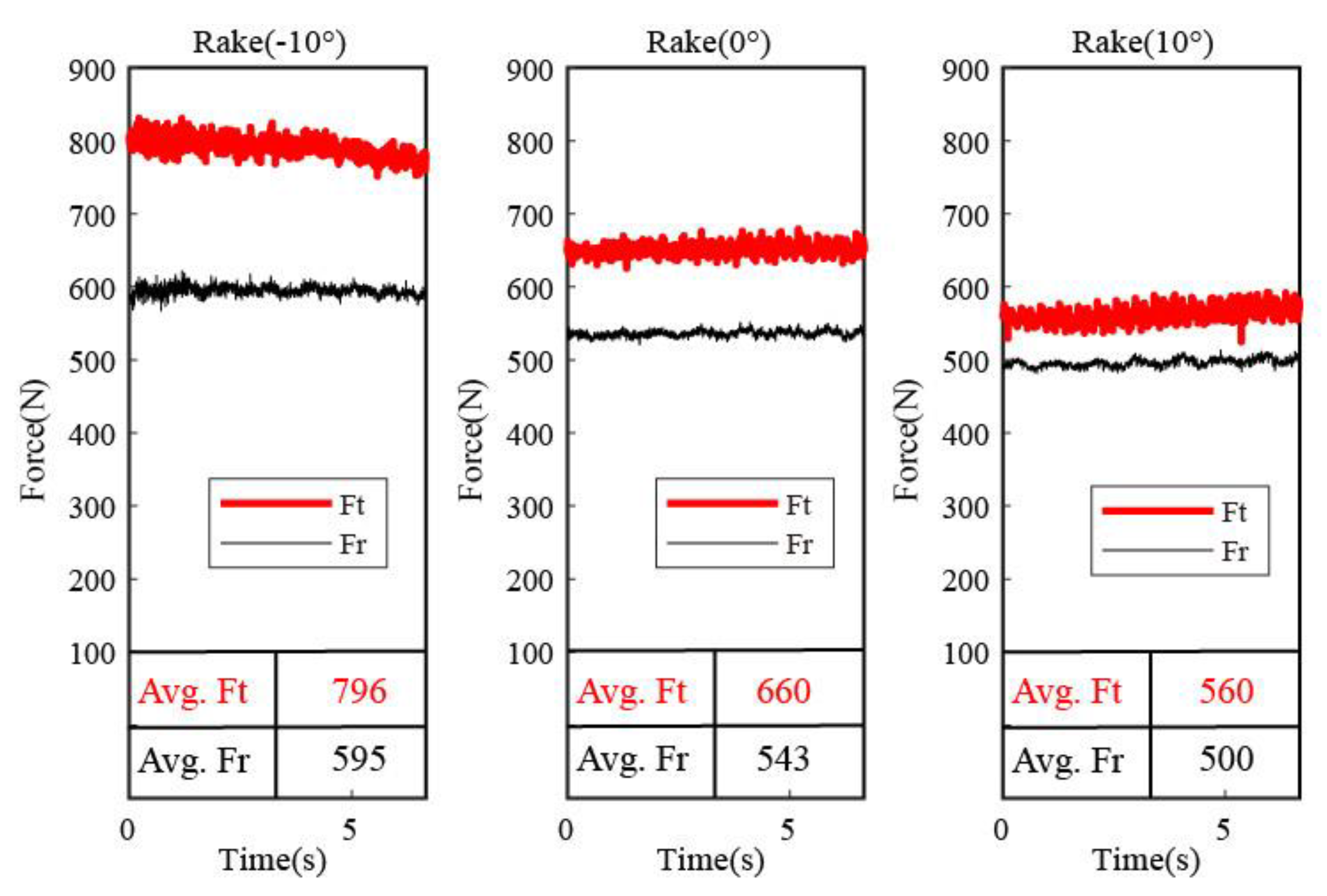
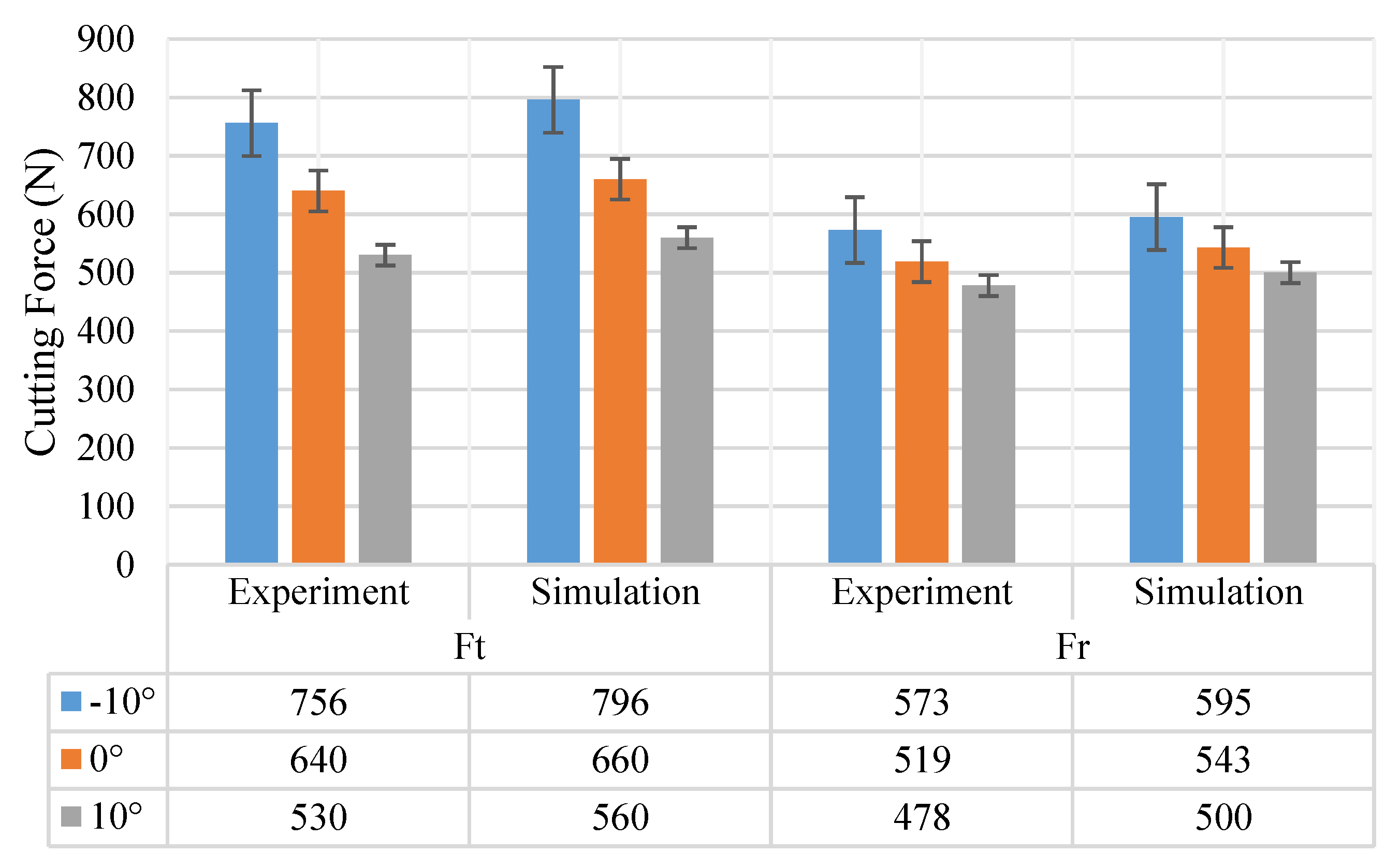
4.1. Influence of Tool Rake Angles on Cutting Force Variation

The cutting force during the machining processes are monitored in both orthogonal directions to analyze the influence of the tool rake angle difference on the cutting performance. As is shown in Figure 5, it is clear that the cutting process with a negative rake angle tool (−10°) presents the highest cutting force (Ft = 796 N and Fr = 595 N) in both directions. As a comparison, the tool with a positive rake angle (+10°) shows the minimum cutting force (Ft = 560 N and Fr = 500 N), whereas the cutting with a neutral rake angle (0°) displays a cutting force (Ft = 660 N and Fr = 543 N) in between the above two cutting conditions. It is obvious that the cutting force component of Ft expresses a larger variation extent when the rake angles of the cutting tool change from negative to positive (796 N to 560 N), compared to the changing of Fr (595 N to 500 N). Similarly, the simulated cutting force (Figure 6) presents almost the same trends, where the cutting force decreases from 796 N to 560 N when the rake angle increases. This is because the rake angle changing causes the variation of cutting force decomposition on the rake face, which can significantly influence the cutting force distribution and changing of the Ft, mainly because of the shear angle increasing (from 30° to 44.5°) during the cutting process (Figure 7), which leads to the cutting force decreasing, as presented in the simulated cutting process with the built FEM model. As seen, a shear angle of 30° is observed in the cutting process with a negative rake angle, and the shear increases to 36° and 44.5°, respectively, when the rake angle increases to 0° and 10°. The results have clearly emphasized that the rake angle increasing can significantly decrease the cutting force during the machining of Inconel 718, which is consistent with the former observation, and that the built model could appropriately replicate the cutting process for further analysis.

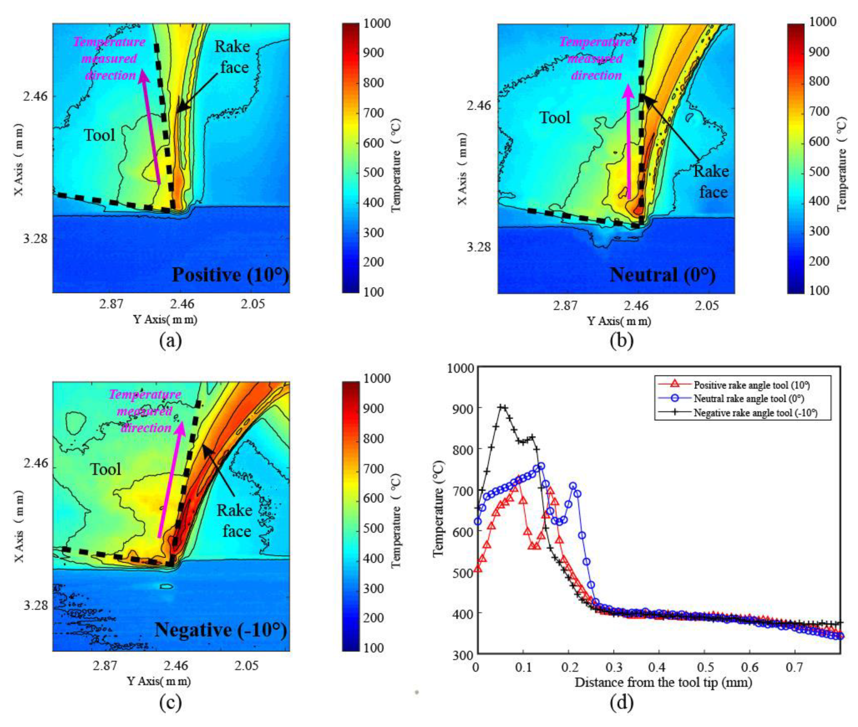
4.2. Temperature Distribution Gradient in Cutting Process

As mentioned in the introduction, it is important to understand the thermal distribution in the cutting areas during the machining process, as it has a significant influence on the material deformation and generated surface integrity, as well as its properties.
The thermal distribution map in the cutting process with different rake angle inserts is first captured (Figure 8), in which the obvious difference can be noticed. As expected the main thermal concentration is located in the front of the tool rake face and the tip areas of the inserts because of the friction in the chip–tool interaction and the tool–workpiece interaction. When comparing the thermal distribution in these different cutting conditions (Figure 8a–c), it is clear that the cutting with the negative rake angle tools shows the highest cutting temperature in the rake face area of the insert, while the maximum temperature decreased continuously following the rake angle increasing (−10° to 0° and then 10°). This observation has been documented well and could be explained by suggesting that when the tool rake angle varies from −10° to 10°, it is harder to remove the materials (proved by the decreasing of the rake angles), thus needs more energy to accomplish the cutting process, as well as larger frictions in the rake face. In addition, from an overall point of view, the chips in all three conditions present a relatively high temperature when compared with the surrounding areas (tool, workpiece, air, etc.), proving that most of the heat has been taken away by the removal of the chips.
Specifically, take the temperature values along the rake face of the inserts (as indicated in the Figure 8a–c: temperature-measured direction) from the tip area as examples for each cutting condition to analyzes and compare the temperature difference caused by the tool rake angle variation. It can be seen from the results (Figure 8d) that the maximum temperature for cutting with a negative rake tool is around 900 ℃, and the values are 750 ℃ and 700 ℃ for neutral and positive rake angle tools. Considering the temperature variation curve for negative tools (Figure 8d), it is worth noting that the temperature does not decrease continuously and linearly along the rake face from the tool tip. Interestingly, the maximum temperature appears at the tip of the tool, which is common sense; however, instead of continuously decreasing from the tip, the temperature achieves another peak after the valley and then decreases to a low temperature. This is because when the chip flows along the rake face, the tightest contact area is not at the cutting edge but at a distance above the cutting edge. At this contact area, the chip implements the highest stress on the rake face and leads to rapid wear, which corresponds to the well-known crater wear in the rake face. The second temperature peaks found in the temperature curves in Figure 8d proves that this contact area experienced an obvious higher temperature than its surroundings, and the same phenomenon could be found for all three curves for the different rake angle tools. The difference in position of the second peak in the temperature curve of the rake face indicates that, for different cutting conditions, the harshest contact area varies as well.
In addition, the simulation results (Figure 9) of the thermal distribution with the employed FEM model presents similar temperature variation trends, where the highest temperature is found with negative rake tools and the lowest one with positive rake tools.

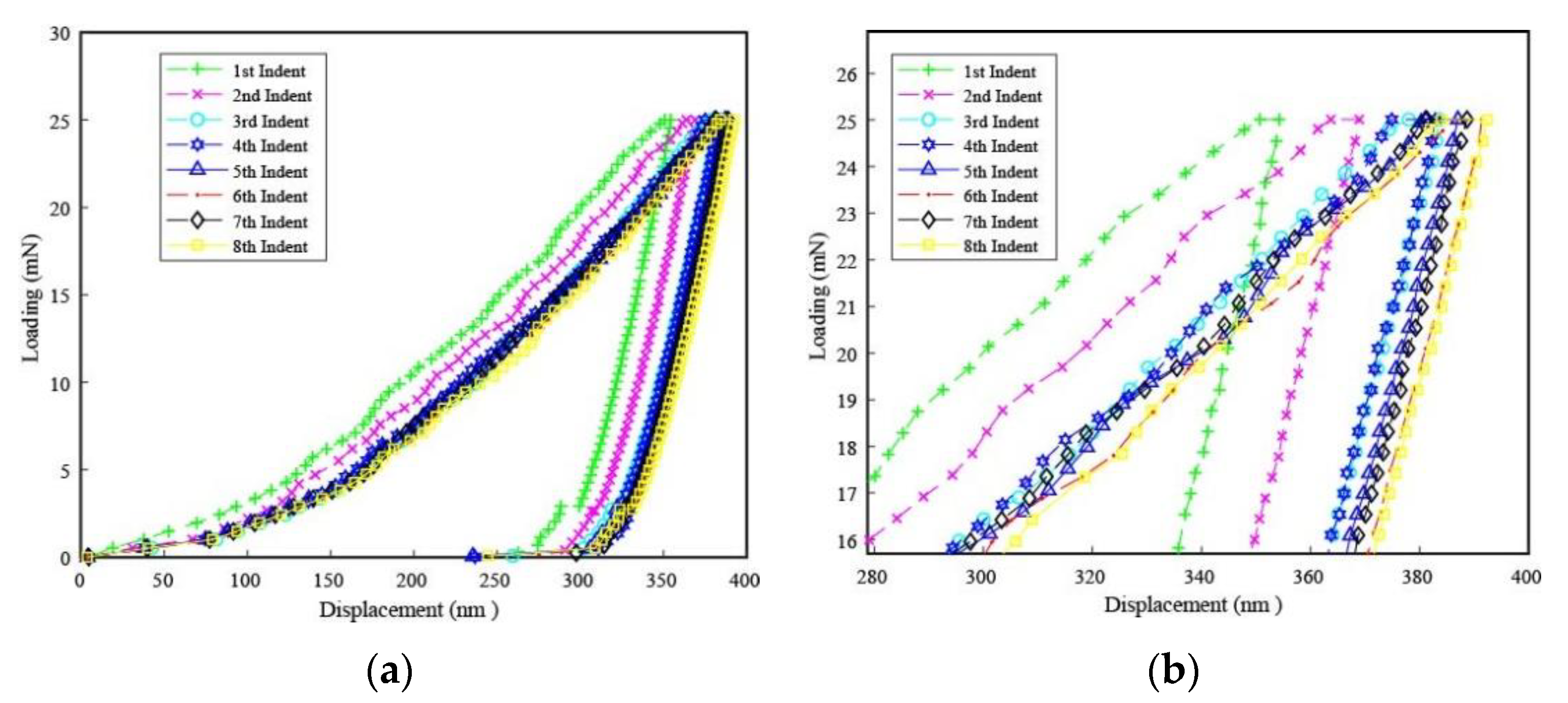
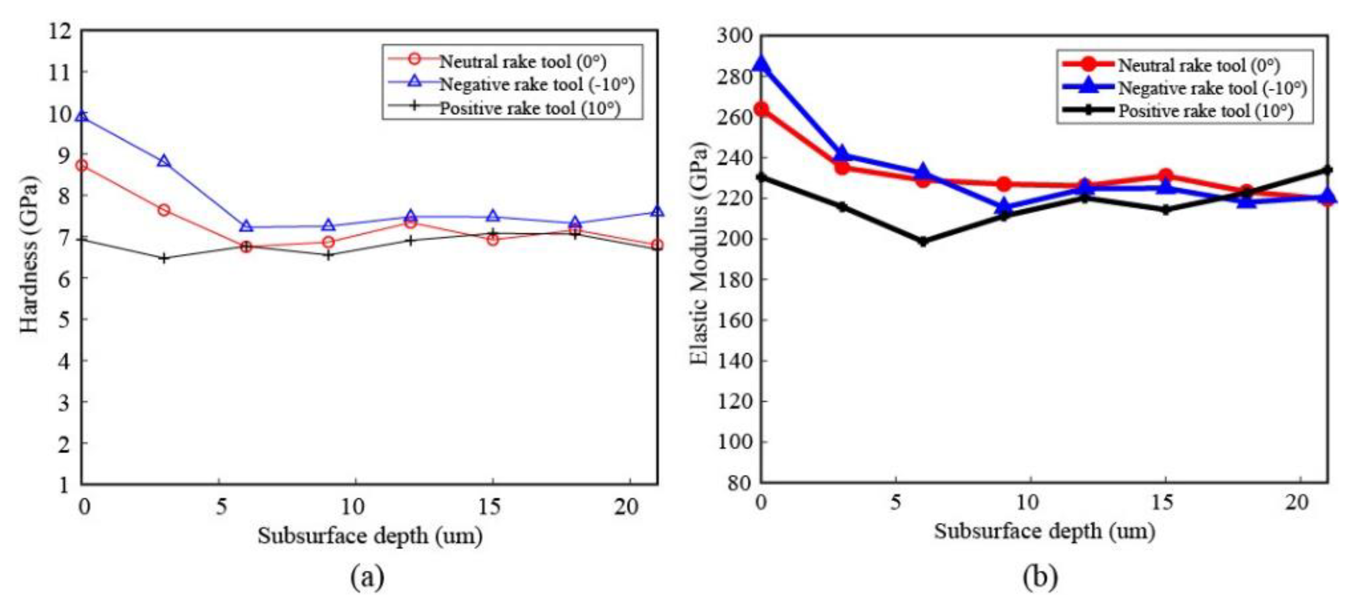
4.3. Subsurface Deformation and Its Mechanical Properties

As is known, the surface integrity of the machined workpiece is the most important aspect that relates to its work performance in the later service period. Thus, the generated surface with different rake angle tools is investigated after the analysis of the cutting process to study its influence on the workpiece quality. For the experimental acquired surface, as seen in Figure 10, the largest deformation depth (10 μm; material drag) is found for the workpiece machined with negative rake angle tools, and a white layer with around 2 μm is also found in the top surface area. As a comparison, the deformation depth of the workpiece for cutting with a neutral rake angle tool presents a deformation depth of a 6-μm- and a 1-μm-thick white layer. Regarding the machined surface generated with the positive rake angle tool, there is almost no clear deformation (less than 1μm) in the subsurface area showing the best surface integrity in the aspect of deformation depth. This is consistent with the above facts that, in the cutting with the positive rake angle tools, the shear angle is larger (easier to remove materials) and the cutting temperature is lower, leading to a better machinability in the cutting condition with positive rake angle tools.
At the same time, the generated subsurface deformation is also simulated by the employed model and the equivalent plastic strain (PEEQ), which stands for the sum of the absolute value of the plastic strains induced by the thermal–mechanical load, and is used to describe the deformation. As seen in Figure 11, the maximum PEEQ value is also found on the surface machined with the negative rake angle tool, showing that, in this cutting condition, the machined surface experienced significant larger deformation loading. There is no doubt that the PEEQ value from the cutting with the positive rake angle tool is the smallest in these three scenarios, which corresponds well with the experimental results.
Apart from the metallurgy properties of the machined workpiece, which is an important indicator for the subsurface deformation, the mechanical characteristics of the subsurface is more critical to the work performance of the machined parts. Nano-indentation is a widely used method to evaluate the material’s hardness or elastic modulus properties, which play significant roles in determining its mechanical characteristics. Thus, nano-indentations are implemented on the machined workpiece in the subsurface areas in order to study the mechanical property variation after machining. As presented in Figure 12a, indentations are carried out by employing a loading controlled method with a loading/unloading speed of 10 mN/s, and an example SEM view of the indentation is shown in Figure 12b.
In particular, the tracked and monitored loading–unloading data of indentations, until a depth of around 24 μm (eight indentations with a 3 μm gap between each two indents) for the workpiece machined with negative rake angle tools, are presented in detail as examples (Figure 13). It is clear that, in the surface area (first indent), the indentation depth is the smallest one, while a larger depth follows (second indent), and then the depths of the next several indentations approach a stable state at the deep area, which is believed to be a bulk material region. A clearer and distinguishable difference in the implemented indentations can be found in the enlarged view (Figure 13b). From the results, it can be assumed that in the near-surface area of the machined workpiece with a positive area, the material is harder to deform when compared with the bulk materials, thus presenting a smaller indentation depth in the same loading levels. This is because the machining process has caused a clear strain-hardening phenomenon on the machined workpiece surface and has less of an influence in the deeper areas.
Comparing the indentations carried out on workpieces machined with different rake angle tools, the nano-hardness profile of subsurface areas (Figure 14a) shows that the cutting with negative rake angles leads to a highest hardness value (around 10 GPa) in the surface area. The workpiece with a neutral rake angle tool displays a smaller value than the negative one, whereas the positive rake angle tool generates a machined surface with almost no significant hardness variation when compared with the bulk material state (around 7 GPa). In the investigation of the corresponding elastic modulus, it shows a similar phenomenon, which also shows a good coherence with the observed deformation in SEM images and the simulated subsurface PEEQ results, where the near-surface area experienced a more severe deformation, and was more obvious when cutting with negative rake angle tools.

5. Conclusions

It has been crucial to study the machining performance of Inconel 718, especially for those workpieces employed in the safety critical areas. As is well known, the rake angles used for cutting tools significantly influence the cutting process, including, but not limited to, the cutting force, temperature, chips formation, and the surface integrity, which is one of the main concerns for manufacturers. However, the understanding of the rake angles variation on the machining process changing is still not clear, especially for the thermal gradient distribution in the cutting areas and the corresponding surface integrity. In the present study, we specifically carried out the influence investigation of rake angles on the cutting process with orthogonal cutting in both experimental and numerical ways. The cutting force variation, thermal gradient distribution changing, and subsurface deformation, as well as the mechanical properties of the machined workpiece, are explored and analyzed. With this investigation, the importance of rake angles on the cutting process has been emphasized, as well as the surface integrity. The good coherence of various factors between the experiment and simulation suggests the possibility of studying the machining process by using numerical methods that can provide more visible results, instead of carrying out massive experiments. The main findings can be summarized as follows:
(1)
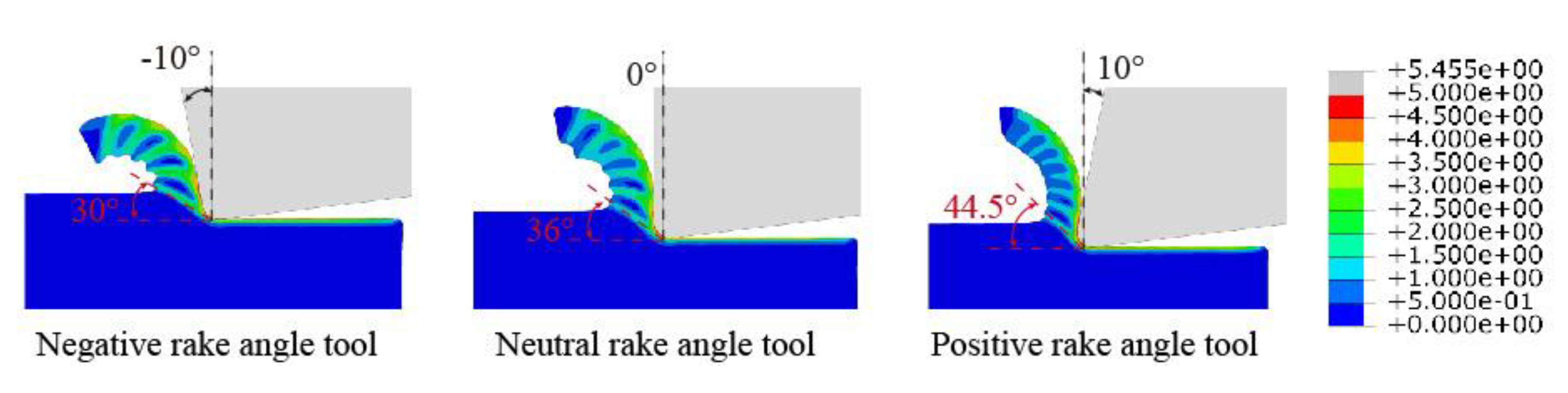
In the comparison of different rake angles, the smallest cutting force and largest shear angles in the cutting process are found. The results have clearly emphasized that the rake angle plays significant roles in determining the cutting force by influencing the rake angles during cutting processes. The increasing of rake angles has a tendency to decrease the cutting force during the machining of Inconel 718, which is consistent with the former observation, and the numerical simulation presents a good coherence with the experimental analysis;
(2)
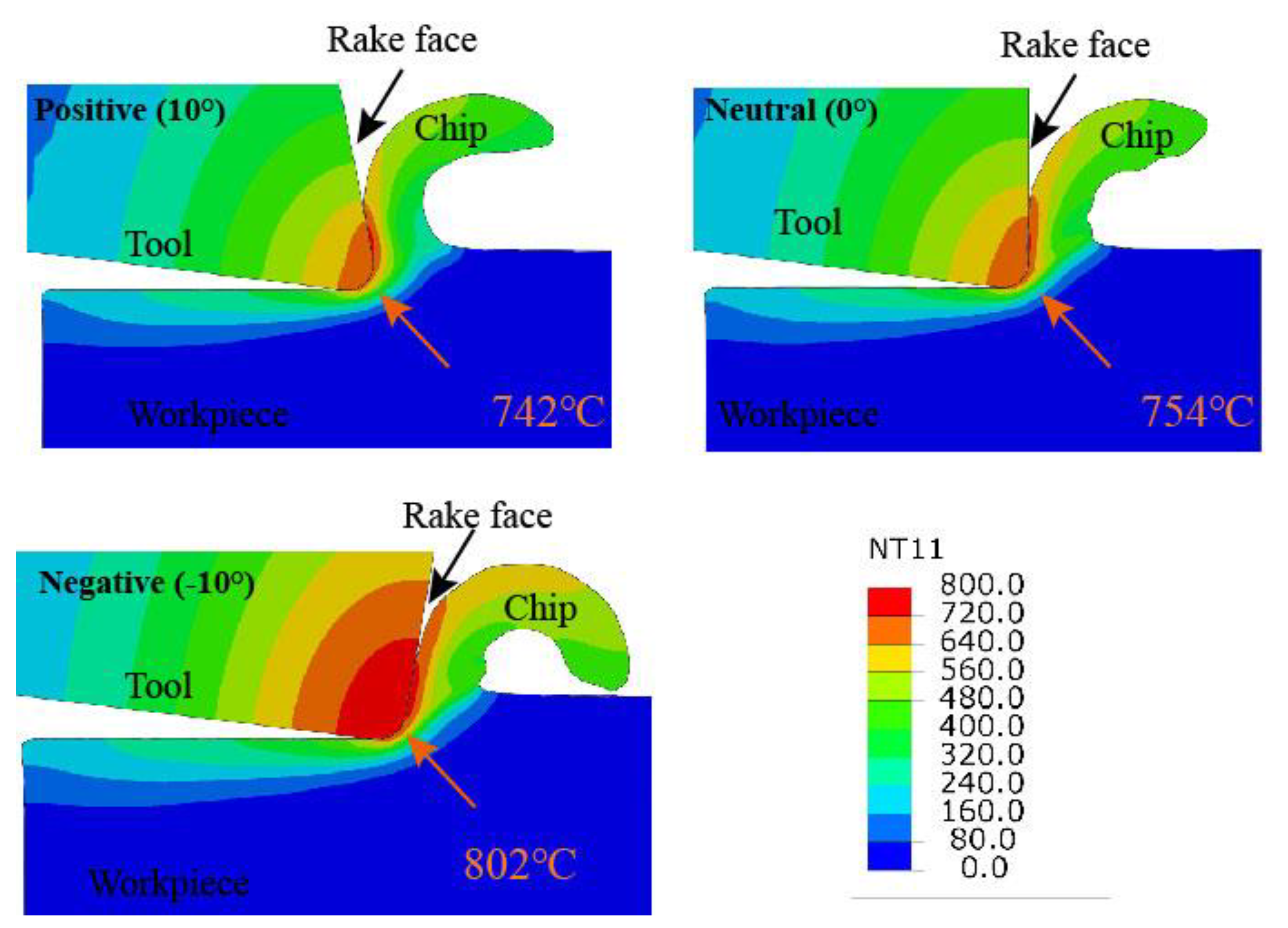
It is clear that the rake angle variation has led to a difference in the thermal map distribution in several presented cutting scenarios, and the negative tool has the trend to increase the cutting temperature. However, it is also worth noting that the temperature in the rake face does not decrease monotonically but achieves another temperature summit in a small distance from the tool tip, which is a clear indication of the reason for crater wear, which has been widely observed;
(3)
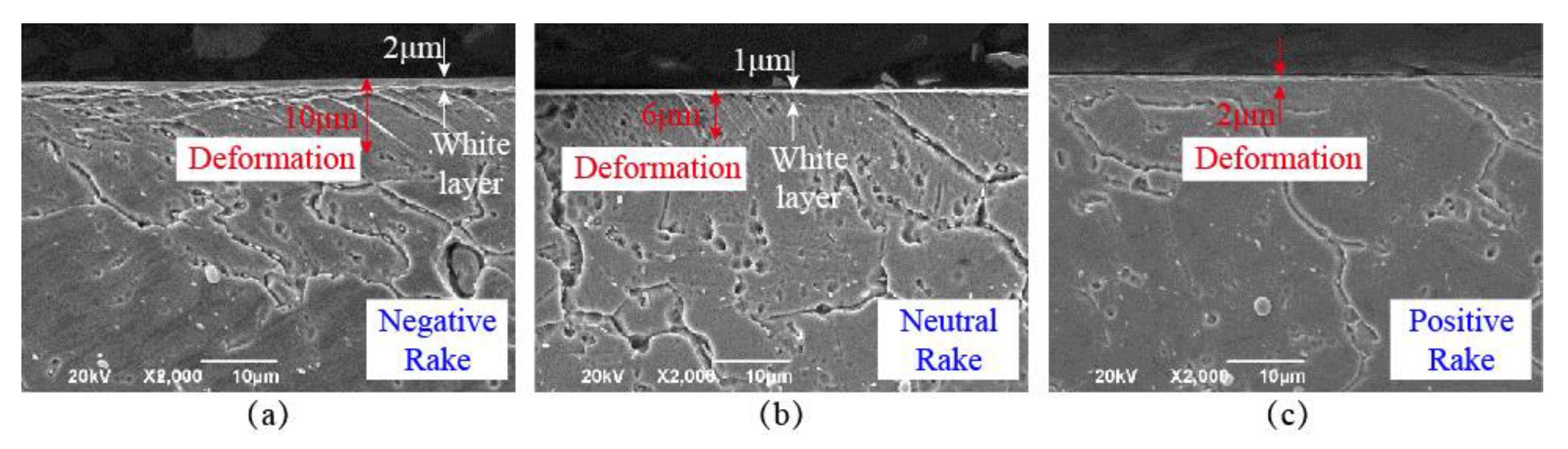
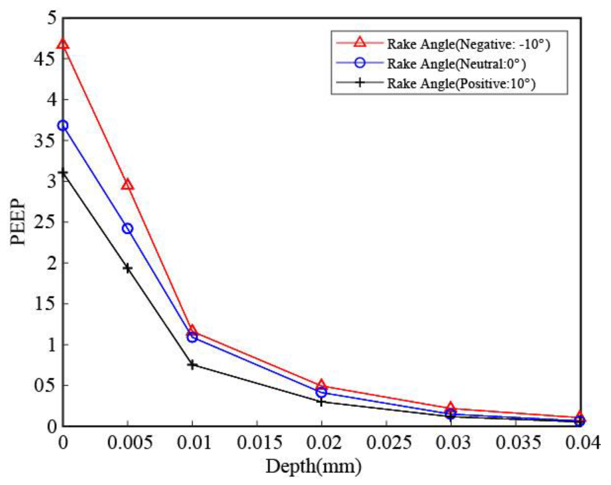
With respect to the surface integrity, the smallest deformation depth is no doubt found for the workpiece generated from positive rake angle tools, and there is no white layer observed when comparing with the neutral and negative rake angle tools, where a clear white layer over 1 μm is noticed. In addition, the mechanical property investigation shows that the strain hardening effect is also the smallest in the subsurface of the workpiece machined from positive rake angle tools, which can be validated from the non-varied hardness and elastic modulus.

Author Contributions

Conceptualization, D.X. and Z.L.; methodology, D.X. and Y.L.; software, Y.L.; validation, D.X., Z.L. and Y.L.; formal analysis, D.X. and L.D.; resources, J.Z.; data curation, D.X. and Y.L.; writing—original draft preparation, D.X., Z.L. and L.D.; writing—review and editing, D.X., Z.L. and Y.L.; funding acquisition, D.X. All authors have read and agreed to the published version of the manuscript.

Funding

This research was funded by MARIE SKŁODOWSKA-CURIE ACTIONS (H2020-MSCA-COFUND-2014): The Integration of Novel Aerospace Technologies “INNOVATIVE” (No: 665468) and and Sichuan Science and Technology Project (2020YFSY0004). The authors want to thank the support from SECO tools on the experimental as well.

Conflicts of Interest

The authors declare no conflict of interest.

References

  1. Miller, S. Advanced materials mean advanced engines. Interdiscip. Sci. Rev. 1995, 20, 117–129. [Google Scholar]
  2. Xu, D.; Liao, Z.; Axinte, D.; Hardy, M. A novel method to continuously map the surface integrity and cutting mechanism transition in various cutting conditions. Int. J. Mach. Tools Manuf. 2020, 151, 103529. [Google Scholar] [CrossRef]
  3. Shang, Z.; Liao, Z.; Sarasua, J.A.; Billingham, J.; Axinte, D. On modelling of laser assisted machining: Forward and inverse problems for heat placement control. Int. J. Mach. Tools Manuf. 2019, 138, 36–50. [Google Scholar] [CrossRef] [Green Version]
  4. M’Saoubi, R.; Axinte, D.; Soo, S.L.; Nobel, C.; Attia, H.; Kappmeyer, G.; Engin, S.; Sim, W.-M. High performance cutting of advanced aerospace alloys and composite materials. CIRP Ann. Technol. 2015, 64, 557–580. [Google Scholar] [CrossRef]
  5. de Garmo, E.P.; Black, J.T.; Kohser, R.A.; Klamecki, B.E. Materials and Process in Manufacturing; Prentice Hall: Hoboken, NJ, USA, 1997. [Google Scholar]
  6. Shizuka, H.; Sakai, K.; Yang, H.; Sonoda, K.; Nagare, T.; Kurebayashi, Y.; Hayakawa, K. Difficult cutting property of NiTi alloy and its mechanism. J. Manuf. Mater. Process. 2020, 4, 124. [Google Scholar]
  7. Shintani, K.; Kato, H.; Fujimura, Y.; Yamamoto, A.; Maeda, T. Cutting performance of CBN tools in machining of nickel based superalloy. Seimitsu Kogaku Kaishi 1992, 58, 1685–1690. [Google Scholar]
  8. Bushlya, V.; Zhou, J.; Ståhl, J.-E. Effect of cutting conditions on machinability of superalloy Inconel 718 during high speed turning with coated and uncoated PCBN tools. Procedia CIRP 2012, 3, 370–375. [Google Scholar] [CrossRef] [Green Version]
  9. Ezugwu, E.O.; Bonney, J.; Yamane, Y. An overview of the machinability of aeroengine alloys. J. Mater. Process. Technol. 2003, 134, 233–253. [Google Scholar] [CrossRef]
  10. Ezugwu, E.O. Key improvements in the machining of difficult-to-cut aerospace superalloys. Int. J. Mach. Tools Manuf. 2005, 45, 1353–1367. [Google Scholar] [CrossRef]
  11. Ulutan, D.; Ozel, T. Machining induced surface integrity in titanium and nickel alloys: A review. Int. J. Mach. Tools Manuf. 2011, 51, 250–280. [Google Scholar] [CrossRef]
  12. Liang, X.; Liu, Z.; Wang, B. State-of-the-art of surface integrity induced by tool wear effects in machining process of titanium and nickel alloys: A review. Meas. J. Int. Meas. Confed. 2019, 132, 150–181. [Google Scholar] [CrossRef]
  13. Jawahir, I.S.; Brinksmeier, E.; M’saoubi, R.; Aspinwall, D.K.; Outeiro, J.C.; Meyer, D.; Umbrello, D.; Jayal, A.D. Surface integrity in material removal processes: Recent advances. CIRP Ann. Technol. 2011, 60, 603–626. [Google Scholar] [CrossRef]
  14. Liao, Z.; la Monaca, A.; Murray, J.; Speidel, A.; Ushmaev, D.; Clare, A.; Axinte, D.; M’Saoubi, R. Surface integrity in metal machining-Part I: Fundamentals of surface characteristics and formation mechanisms. Int. J. Mach. Tools Manuf. 2020, 162, 103687. [Google Scholar] [CrossRef]
  15. Zhou, J.; Chen, Z.; Persson, H.; Peng, R.L.; M’Saoubi, R.; Gustasson, D. Comparative assessment of the surface integrity of AD730® and IN718 superalloys in high-speed turning with a CBN tool. J. Manuf. Mater. Process. 2019, 3, 73. [Google Scholar] [CrossRef] [Green Version]
  16. Wolf, T.; Iovkov, I.; Biermann, D. Influence of a Discontinuous Process Strategy on Microstructure and Microhardness in Drilling Inconel 718. J. Manuf. Mater. Process. 2021, 5, 43. [Google Scholar]
  17. Ozel, T.; Llanos, I.; Soriano, J.; Arrazola, P.-J. 3D finite element modelling of chip formation process for machining Inconel 718: Comparison of FE software predictions. Mach. Sci. Technol. 2011, 15, 21–46. [Google Scholar] [CrossRef]
  18. Pu, Z.; Umbrello, D.; Dillon, O.W., Jr.; Jawahir, I.S. Finite element simulation of residual stresses in cryogenic machining of AZ31B Mg alloy. Procedia CIRP 2014, 13, 282–287. [Google Scholar] [CrossRef] [Green Version]
  19. Ducobu, F.; Rivière-Lorphèvre, E.; Filippi, E. Numerical contribution to the comprehension of saw-toothed Ti6Al4V chip formation in orthogonal cutting. Int. J. Mech. Sci. 2014, 81, 77–87. [Google Scholar] [CrossRef]
  20. Calamaz, M.; Coupard, D.; Girot, F. A new material model for 2D numerical simulation of serrated chip formation when machining titanium alloy Ti-6Al-4V. Int. J. Mach. Tools Manuf. 2008, 48, 275–288. [Google Scholar] [CrossRef] [Green Version]
  21. Nasr, M.N.A.; Ng, E.-G.; Elbestawi, M.A. A modified time-efficient FE approach for predicting machining-induced residual stresses. Finite Elem. Anal. Des. 2008, 44, 149–161. [Google Scholar]
  22. Nasr, M.N.A.; Ng, E.-G.; Elbestawi, M.A. Modelling the effects of tool-edge radius on residual stresses when orthogonal cutting AISI 316L. Int. J. Mach. Tools Manuf. 2007, 47, 401–411. [Google Scholar] [CrossRef]
  23. Liu, Y.; Agmell, M.; Xu, D.; Ahadi, A.; Stahl, J.E.; Zhou, J. Numerical contribution to segmented chip effect on residual stress distribution in orthogonal cutting of Inconel 718. Int. J. Adv. Manuf. Technol. 2020, 109, 993–1005. [Google Scholar] [CrossRef]
  24. Xu, D.; Liao, Z.; Axinte, D.; Sarasua, J.A.; M’Saoubi, R.; Wretland, A. Investigation of surface integrity in laser-assisted machining of nickel based superalloy. Mater. Des. 2020, 194, 108851. [Google Scholar] [CrossRef]
  25. Thakur, D.G.; Ramamoorthy, B.; Vijayaraghavan, L. Study on the machinability characteristics of superalloy Inconel 718 during high speed turning. Mater. Des. 2009, 30, 1718–1725. [Google Scholar] [CrossRef]
  26. Ducobu, F.; Rivière-Lorphèvre, E.; Filippi, E. Application of the Coupled Eulerian-Lagrangian (CEL) method to the modeling of orthogonal cutting. Eur. J. Mech. A/Solids. 2016, 59, 58–66. [Google Scholar] [CrossRef]
  27. Arrazola, P.-J.; Aristimuno, P.; Soler, D.; Childs, T. Metal cutting experiments and modelling for improved determination of chip/tool contact temperature by infrared thermography. CIRP Ann. 2015, 64, 57–60. [Google Scholar] [CrossRef]
  28. Agmell, M.; Bushlya, V.; M’Saoubi, R.; Gutnichenko, O.; Zaporozhets, O.; Laakso, S.V.A.; Ståhl, J.-E. Investigation of mechanical and thermal loads in pcBN tooling during machining of Inconel 718. Int. J. Adv. Manuf. Technol. 2020, 107, 1451–1462. [Google Scholar] [CrossRef] [Green Version]
  29. Ducobu, F.; Rivière-Lorphèvre, E.; Filippi, E. Mesh influence in orthogonal cutting modelling with the Coupled Eulerian-Lagrangian (CEL) method. Eur. J. Mech. A/Solids. 2017, 65, 324–335. [Google Scholar] [CrossRef]
  30. Chen, L.; Mi, G.; Zhang, X.; Wang, C. Numerical and experimental investigation on microstructure and residual stress of multi-pass hybrid laser-arc welded 316L steel. Mater. Des. 2019, 168, 107653. [Google Scholar] [CrossRef]
  31. Sartori, E. Convection coefficient equations for forced air flow over flat surfaces. Sol. Energy 2006, 80, 1063–1071. [Google Scholar] [CrossRef]
Figure 1. Measured three-dimensional geometry of employed cutting inserts edge.
Jmmp 05 00100 g001
Figure 2. Employed orthogonal cutting test arrangement with customized tool inserts.
Jmmp 05 00100 g002
Figure 3. The arrangements for temperature capturing and the indication of the tool–workpiece interaction.
Jmmp 05 00100 g003
Figure 4. Flow chart of the simulation approach, and the initial geometry and boundary conditions for the heat transfer and cutting simulation with a rake angle of −10°.
Jmmp 05 00100 g004
Figure 5. Monitored cutting force and comparison between inserts with different rake angles.
Jmmp 05 00100 g005
Figure 6. Comparison of simulated cutting force and experimental cutting force.
Jmmp 05 00100 g006
Figure 7. Simulated cutting process employing cutting inserts with different rake angles.
Jmmp 05 00100 g007
Figure 8. The IR image obtained in the orthogonal cutting of Inconel 718 with different rake angle tools. (a) Thermal distribution for positive rake angles, (b) thermal distribution for neutral rake angles, (c) thermal distribution for negative rake angles and (d) the temperature gradient along rake face of different geometry tools.
Jmmp 05 00100 g008
Figure 9. The simulated thermal map distribution in the orthogonal cutting of Inconel 718 with different rake angle tools.
Jmmp 05 00100 g009
Figure 10. SEM images revealing the subsurface deformation for workpiece machined with different rake angle tools.
Jmmp 05 00100 g010
Figure 11. Simulated subsurface deformation of workpiece machined with different rake angle tools.
Jmmp 05 00100 g011
Figure 12. Loading–time curves for the indents carried out in the surface areas of machined workpiece (a) and examples of SEM images of indents (b).
Jmmp 05 00100 g012
Figure 13. Loading–displacement curves of nano-indents in the subsurface areas of workpiece machined with negative (−10°) rake angles. (a) The full view of loading displacement curves and (b) corresponding enlarge view of top areas.
Jmmp 05 00100 g013
Figure 14. Nano-hardness and elastic modulus variation profile in the subsurface area of machined workpiece. (a) The measured hardness in subsurface areas of machined workpiece and (b) the corresponding elastic modulus in subsurface areas.
Jmmp 05 00100 g014
Table 1. Main chemical composition of employed Inconel 718, %.
TiCrCuMoNbNiCoMnAlFe
1.0518.500.213.104.9552.180.760.170.41Balance
Table 2. Main properties of employed materials in orthogonal cutting tests.
PropertiesWorkpiece (Inconel 718)Tool (Uncoated Cemented Carbide)
Thermal conductivity (W/m °C)12 (20 °C)
24 (900 °C)
82
Density (kg/m3)822114860
Young’s modulus E (GPa)212600
Poisson’s ratio v 0.2940.2
Expansion (°C−1)1.2 × 10⁻⁵ (20 °C)
1.7× 10⁻⁵ (900 °C)
5.2
Inelastic heat fraction0.9-
Specific heat (J/Kg °C)440 (20 °C)249.8
680 (900 °C)
Troom (°C)25 25
Tmelt (°C)1344-
VB-200 um
Johnson–Cook constantsA (Mpa) B (Mpa) Cnm
(Inconel 718)13771243.50.00450.67671.2
Table 3. Implemented cutting test parameters and conditions.
TestRake Angle
(°)
Edge Radius (um)Vc
(m/min)
Depth of Cut (mm)Cutting Width (mm)
1−1045500.072
2045500.072
31045500.072
Publisher’s Note: MDPI stays neutral with regard to jurisdictional claims in published maps and institutional affiliations.

