Article

Electrohydraulic Forming of Low Volume and Prototype Parts: Process Design and Practical Examples

by
Alexander V. Mamutov
1,*,
Sergey F. Golovashchenko
1,
Nicolas M. Bessonov
2 and
Viacheslav S. Mamutov
3
1
Mechanical Engineering Department, School of Engineering and Computer Science, Oakland University, Rochester, MI 48309, USA
2
Institute for Problems in Mechanical Engineering of the Russian Academy of Sciences, 199178 St. Petersburg, Russia
3
Peter the Great St. Petersburg Polytechnic University, Institute of Machinery, Materials, and Transport, 195251 St. Petersburg, Russia
*
Author to whom correspondence should be addressed.
J. Manuf. Mater. Process. 2021, 5(2), 47; https://doi.org/10.3390/jmmp5020047
Submission received: 30 March 2021 / Revised: 5 May 2021 / Accepted: 10 May 2021 / Published: 13 May 2021
(This article belongs to the Special Issue Impulse-Based Manufacturing Technologies)

Abstract

:
Electro-Hydraulic Forming (EHF) is a high rate sheet metal forming process based on the electrical discharge of high voltage capacitors in a water-filled chamber. During the discharge, the pulsed pressure wave propagates from the electrodes and forms a sheet metal blank into a die. The performed literature review shows that this technology is suitable for forming parts of a broad range of dimensions and complex shapes. One of the barriers for broader implementation of this technology is the complexity of a full-scale simulation of EHF which includes the simulation of an expanding plasma channel, the propagation of waves in a fluid filled chamber, and the high-rate forming of a blank in contact with a rigid die. The objective of the presented paper is to establish methods of designing the EHF processes using simplified methods. The paper describes a numerical approach on how to define the shape of preforming pockets. The concept includes imposing principal strains from the formed blank into the initial mesh of the flat blank. The principal strains are applied with the opposite sign creating compression in the flat blank. The corresponding principal stresses in the blank are calculated based upon Hooke’s law. The blank is then virtually placed between two rigid plates. One of the plates has windows into which the material is getting bulged driven by the in-plane compressive stresses. The prediction of the shape of the bulged sheet provides the information on the shape of the preforming pockets. It is experimentally demonstrated that using these approaches, EHF forming is feasible for forming of a fragment of a decklid panel and a deep panel with complex curvature.

1. Introduction

The trend of creating global vehicle architecture in automotive industry described by Ferreira and Kaminski [1] is broadly spreading among automotive manufacturers. Sharing components between different platforms and vehicles leads to overall increase in production volumes and generates a need for high productivity manufacturing processes. In stamping of sheet metal components, servopress equipment becomes more popular due to increased productivity compared to the mechanical presses broadly used in industry. However, the automotive industry has a strong demand for low volume technologies, which would enable low cost production of prototype parts. Sheet metal forming processes where one side of the stamping die (typically a punch) is replaced by pressure were described in a number of publications and reference books on metal forming [2]. These processes have the strong advantages of lower tool cost due to elimination of the need to cast and machine one side of the die as well as due to no further need for accurate alignment of matching portions of the die. These simplifications also shorten the tool development cycle. This group of metal forming processes are typically employed for deep drawing and stretch drawing of sheets and forming of tubular blanks by applying forming pressure from inside the tubes. Among them are: (a) quasistatic processes, such as superplastic forming (SPF), hydroforming (HF), rubber/polyurethane forming (RF), and (b) high rate forming processes, such as electromagnetic forming (EMF), electrohydraulic forming (EHF) and explosive forming (EF). EMF, EHF, and EF belong, according to Wilson [3], to the group of high velocity forming technologies.
Quasistatic processes are simpler for analysis and experimental tryout, since they are similar to traditional sheet metal forming operations where stamping presses are utilized. A major drawback of these processes is usually in the significant force required to form the blank: pressure that is needed to form the smallest radius of the die cavity defines the pressure that has to be applied to the overall surface of the blank inside the die cavity. This condition leads to significant investments for forming equipment required to implement these processes. The need to manufacture the prototype parts motivated broad usage of hydroforming processes employing a polyurethane sheet as a membrane to separate the sheet metal blank from the fluid. This technology is known as the flexform process [4]. The term of crush forming is often utilized for these processes because no binder is being used to control sheet metal flow into the forming die.
The high speed forming technologies were mentioned for industrial applications starting from 1960s [5], and more extensively in early 1970s [6], mainly due to several advantages which these processes have compared to quasistatic processes. The most impressive advantage was in the capability to form parts with dimensions of several meters. Forming such parts was impossible during that stage of development of metal forming technology and equipment. Callender [7] reported the results of EHF with a net of wire bridges to form a dish component 3 m in diameter. Epoxy lined dies were used in these experiments which started showing degradation after forming twelve blanks. Felts [8] demonstrated EHF forming of dish components with flanged holes from Aluminum 6016-T0 as well as deep drawing box type shapes from deep drawing quality steel. A variety of die materials starting from steel-reinforced concrete, chopped glass-fiber-reinforced epoxy resin and, in some configurations, tool steel were used.
Hanley [9] carried out a very detailed review of applications of high speed forming technologies at General Dynamics Corporation: EHF was considered the most efficient method for forming of tubular blanks with potential punching of holes in the same operation as forming the shape of the part. A typical diameter of tubular blanks was 30-0 mm. The electrode system employed in studies reviewed in [9] was based upon wire bridges, which had to be replaced after each high-voltage discharge. The dies were designed consisting of two halves based upon the clam shell approach. Implementation of EHF allowed a reduction in the number of manufacturing steps and eliminated the need to subdivide one part into several independently stamped and further joined smaller parts. The production cycle for the EHF processes described in [9] was reported as several minutes. Feddersen [10] illustrated a number of applications of tube expansion by EHF including one case where a window was pierced in the tubular component.
Callender [7] also described experiments on EHF of a conical shape welded blank into an ogival shape. Schrom [11] demonstrated a laboratory EHF process for bulging sheet metals and expanding thin cylindrical shells indicating that Aluminum foil of 12.7 mm width can substantially increase the efficiency of the process compared to other bridge materials and no-bridge tooling configuration. The attempt to study the efficiency of energy transfer in EHF was made by Duncan and Johnson [12] for both sheet forming and tube forming. Duncan and Johnson [12] demonstrated forming of a dish with a lot of fine features which certainly increased the complexity of the EHF operation compared to previous cases.
Bruno [5] illustrated several examples of duct parts from special alloys for aerospace applications: various shapes were formed by electric discharges inside cylindrical shells. This type of part is difficult to make by other methods. Similarly, Davies, and Austin [6] illustrated an application of the EHF process for the piercing and flanging of holes in the tubular thin walled extrusion made of pure aluminum. However, very limited details of the studied EHF process were disclosed. Most of the applications belonged to the defense industry which limited publishing of technical details. More importantly, the methodologies of formability analysis were in their infancy: the initial ideas on Forming Limit Diagram development were published several years later for biaxial stretching by Keeler [13] and for stretching–compression by Goodwin [14].
During the last twenty-five years, a number of experimental studies illustrated that the very significant improvement in sheet metal formability can be attributed to high strain rate, low friction, and the coining effect. This effect is based upon through thickness compression during high velocity impact between the blank and the die surface. In [15] a significant improvement of formability was observed for AA6061-T4. Imbert et al. reported visible improvement in formability for two aluminum alloys: 6111-T4 and 5754 [16]. Authors [17] reported formability improvements for AA5182. Dariani et al. [18] indicated an extension of formability for 1045 steel and 6061-T6 aluminum alloy. Golovashchenko et al. [19] quantified formability improvements for four dual phase steels: DP500, DP590, DP780, and DP980. Analysis of microstructure and porosity development in quasistatic and EHF processes [20] indicated that both high velocity impact and high strain rate create favorable conditions for DP780 and DP500. Jenab et al. [21] arrived to similar conclusions for AA5182. In addition, calibration of the formed part is provided in the same tool, minimizing springback. In a traditional stamping process, either a restrike die would be needed to minimize springback, adjustment of the die surface to compensate for springback, or additional stretching of the blank using a lockbead at the very end of the forming process to minimize springback.
Even though explosive forming processes provide nearly unlimited capabilities from the perspective of achievable pressure and impact speeds, the safety implications often limit its application for industrial processes. A review of more recent results on EF processes was published by Mynors and Zhang [22].
The intention to achieve similar benefits without safety issues motivated studies of EHF and EMF forming technologies. Psyk et al. [23] performed a very detailed analysis on various aspects of EMF processes. These aspects included coil designs, details on forming and joining processes, and recently developed numerical and analytical models. The major limitation of EMF technology is in a significant reduction in forming pressure applied to the sheet when it moves further away from the inductor generating electromagnetic field as well as in the requirement of good electrical conductivity for the material of the blank and for the material of the coil. A typical EMF coil includes insulation material which, in most cases, limits the structural strength of the coil. A reduction in pulsed pressure as a result of the blank getting further away from the coil limits the application of EMF processes to either rather shallow shapes or the shapes where the final forming is possible without backing pressure.
Recent studies on EHF mostly concentrate on the improved formability demonstrated in free bulging, for example by Maris et al. [24] and the forming of a sheet into very simple shapes such as conical or V-shape, for example, by Cheng et al. [25]. The general trend is that substantial improvement can be achieved for the forming of Aluminum alloys, dual phase steels and a variety of other materials.
Based upon experimental study performed by Golovashchenko et al. [26], EHF technology has the strongest potential among pulsed forming processes to be applied to forming deep cavities with sharp corners and shapes that are more complex. Authors [26] demonstrated that a sheet metal blank can be formed by sequential discharges of several pairs of electrodes with no specific requirement to the parameters of grain structure (as for SPF), or high electrical conductivity (as in EMF processes). Employment of several pairs of electrodes enables the pressure distribution applied to the sheet metal blank to be tailored in a broad range: several discharges generated by multiple electrodes may create a more favorable mechanism of sheet metal flow into the cavity of the die.
Another opportunity for formability improvement was discussed in [26] where the blank was preformed into a shape which utilized formability of the adjacent portions of the blank to fill the corners of the die shape. Authors [27] demonstrated that EHF has a better capability to form sharp corners than quasistatic hydroforming described in [28] and also requires a lower clamping force employing the inertia of the tool and the clamping press, which requires a much smaller capital investment. A reconfigurable EHF tool comprising of several small size chambers can be assembled together for the forming of various shapes, as suggested by Golovashchenko [29]. The downside of the EHF process is in the necessity to evacuate and refill at least some portion of the EHF chamber with water for every formed part.
A very important advancement which started changing the sheet metal forming industry in the late 1980s was the developing capability to simulate sheet metal forming processes. The explicit integration procedures initially developed for simulation of explosions in defense applications very naturally fit into high velocity forming processes. The models considering EHF process as dynamic hydroforming with uniformly applied pressure were developed in the late 1980s, for example by Vagin et al. [30]. The dynamics of pressure distribution in the EHF chamber were studied in [30] experimentally by: (a) inserting piezo sensors capable of surviving such a high level of dynamic pressure in the chamber and (b) by using a membrane method as proposed by Cole [31] accounting for the pressure level on the surface of the membrane by the local displacement of the membrane in a small diameter hole. Knyazev and Zhovnovatuk [32] performed similar measurements for a multi-electrode chamber. Such experimental measurements provided the justification for applying the dynamic pressure to the surface of the blank.
Melander et al. [33] analyzed formation of a conical shape and also free bulging of the blank into an open die cavity. Simplifying assumptions regarding pressure distribution in the chamber and percentage of reflection of pressure from the walls of the chamber were employed. Rohatgi et al. [17] approximated the pressure distribution on the surface of the round blank with a linear function along the radius of the blank assuming the exponential decay of pressure as a function of time. Hassannejadasl et al. [34] assumed hydrodynamic pressure in the model as an acceleration of fluid particles on a spherical surface inside the chamber. The model was calibrated using the experimental data on free bulging of the blank. The time function for the acceleration was selected as a half of a sinusoid. In this case, the pressure on the sheet metal blank was not considered a uniform or constant distribution: it was calculated from the hydrodynamic analysis. The simplifying assumption regarding the spherical impact as a method of energy deposition worked well for the analysis of sheet metal forming into a conical die. However, in order to design an EHF chamber of a more complex shape, more realistic energy deposition accounting for the shape of the chamber is needed.
Vohnout et al. [35] analyzed pressure heterogeneity in a cylindrical EHF chamber by using a membrane penetration method. The numerical simulation was performed using CTH code simulating explosions. The equivalence between the explosion and EHF processes was not very clearly established; however, the dynamic pressure distribution could be similar with the exception that EHF provides substantially slower energy deposition compared to a chemical explosion. Based on the performed analysis, it was concluded that pressure distribution is very sensitive to changes in the location of the energy source (explosion in the case of the performed theoretical analysis).
Mamutov et al. [36] described a more general algorithm based upon LS-DYNA commercial code capable of predicting pressure wave formation as a result of a high voltage discharge in a water filled chamber. This algorithm is capable of analyzing the blank formation for a general configuration of the electrode system. The drawback of this approach is that, at current computational capabilities, many hours of computations on a multiprocessor supercomputer are required to predict multi discharge formation of the blank. However, without pre-existing chamber design, these calculations might show that (a) a different configuration of the EHF chamber is needed, (b) the blank has insufficient formability to fill the required shape, and (c) the available equipment cannot provide a sufficient discharge current. If any of these situations occur, there may be a need to run multiple other configurations of the EHF chamber and sheet metal forming process. In this study, a simplified approach is proposed which is expected to assist in a much faster design of the EHF chamber configuration capable of forming the desired shape from the targeted sheet material.
Woo et al. [37] studied formation of pressure pulses in the EHF chamber by employing an ALE numerical approach in LS-DYNA, illustrating that this powerful approach enables a detailed study of wave reflection and propagation in EHF chamber. Woo et al. [38] simulated the EHF free forming process into an open round window and used the model described in [37] to identify the material parameters of Aluminum sheet 6061-T6 which would have the best correlation with experimental data in free forming conditions.
Jenab et al. [39] described a simplified methodology of EHF process analysis by assuming that the EHF load is applied as a pressure pulse similar to an explosive load known from the literature instead of taking into account the history of pressure wave propagation through the EHF chamber. Authors [39] concentrated on studying the details of AA5182 sheet forming into an open round window or into a conical die analyzing different material models and neural algorithms accounting for material high rate behavior.
A tryout study was performed experimentally in [40] to demonstrate the overall feasibility to form various sheets with EHF using a pulse generator assembled by researchers from high voltage capacitors. This study confirmed that the EHF technology can be employed as a very simple process for forming tryout.
Xiong et al. [41] developed a simplified engineering model predicting pulse pressure parameters as a function of distance from the discharge location in an electrohydraulic chamber and applied it to the analysis of impact cracking test conducted on cement samples.
As it can be seen in the presented literature review, the overall advantages of the EHF processes is in extended material formability due to high strain rates, coining effects, and no friction on one side of the die. However, an additional advantage of redistributing strains in a formed blank based upon flexible loading in media forming processes compared to traditional stamping in two-sided dies has not been explored in significant detail.
The idea of preforming the sheet in a traditional stamping die and then applying the pulsed pressure to form the material into a sharp radius was discussed by Daehn et al. [42] as electromagnetic forming of a door inner part where sheet metal blank was originally preformed in two-sided dies, and then a restrike electromagnetic forming operation was applied. An idea of preforming a sheet by gaining the metal in the pockets adjacent to the areas of excessive strains was introduced by Golovashchenko et al. [43]. The initial concept was to form the preform shape similarly to the final shape of the part with the exception of the areas with sharp corners, which would be supplemented with donor pockets minimizing stretching of sheet in these areas. The cost of such a preforming die would be similar to the cost of the die with the final shape of the part. Overall, this technology would require an incremental increase in the cost of the dies. In this paper a further advancement of this concept in the direction of significantly simplifying the shape and minimizing the cost of the preform die [44] will be discussed.
The objective of this paper is to introduce a simplified methodology of design for EHF processes and to illustrate a low-cost preform concept for the case where extended formability of EHF process is not sufficient to make the targeted shape. Therefore, the proposed concept can be viewed as a further step to enable usage of higher strength, lighter and less formable materials in the automotive industry.

2. Proposed Method of Developing EHF Processes

This paper represents an attempt to formulate the necessary and optional steps to develop the EHF prototype process for a new application where benefits of this pulsed forming technology can be substantial either due to a simpler tooling design, due to the capability of the EHF method produce more deformation from a deformed sheet without fracture, or take advantage of the soft application of the forming load compared to stamping in traditional rigid dies. The authors admit that the proposed method is still in an early phase of development and will further mature with broader implementation of EHF processes in production.
There are following important questions which need to be answered at the development stage of the prototype EHF process:
(a)
whether the part can be formed using the EHF process from the sheet material proposed by the product designer;
(b)
if the sheet material candidate does not provide sufficient formability even with extra formability offered by EHF, decide whether the preforming process lowering the maximum strains can help to fill the shape without fracture;
(c)
whether the available pulsed equipment and the EHF chamber provide a sufficient amount of pulsed pressure to fill all the details of the formed shape;
(d)
if a new EHF chamber is being developed, decide where the electrodes should be positioned to achieve required pressures in the most difficult to form areas of the part, which are typically in the areas of sharper corners at the bottom of the formed cavity.
Numerical simulation or experimental tryout can be selected to execute these steps, and the specific actions strongly depend on accumulated experience and necessary efforts to successfully achieve the goal taking into account the existing experience in EHF technology at a particular organization, the timeline and available resources. An important point of this paper is the selection of quick and efficient simplified approaches not requiring lengthy development and very significant computational efforts. The following sequence of steps addresses the questions listed above.
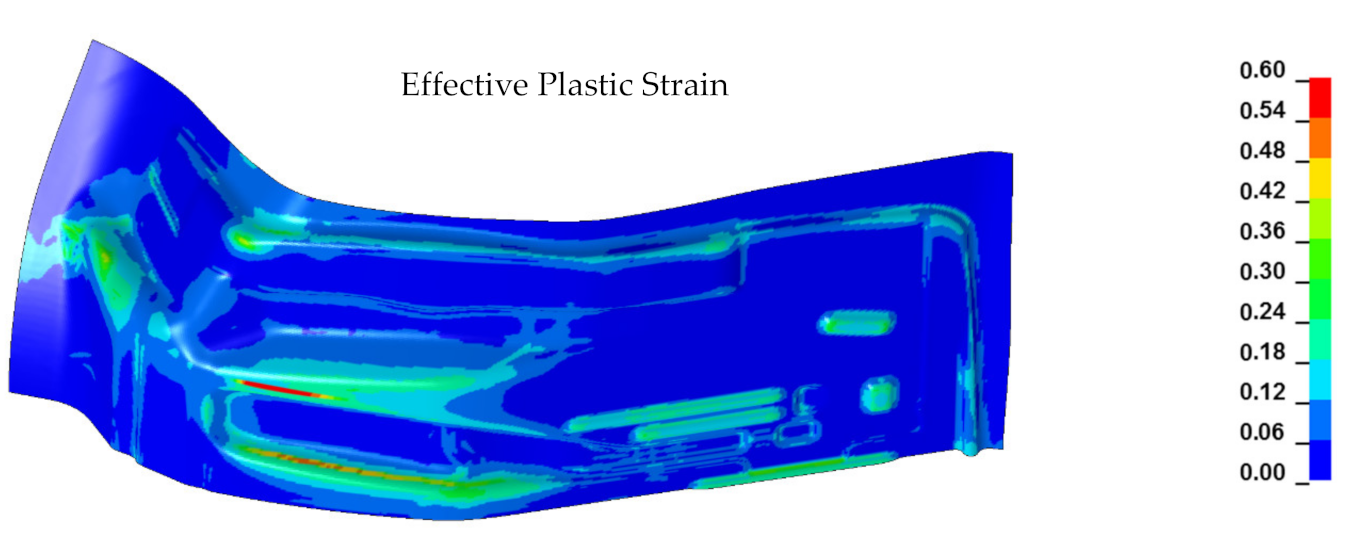
  • Identify the areas of the part that are the most difficult to fill and require the largest pressure. A simplified numerical approach assuming a uniform pressure forming load in quasi static formulation is capable to achieve this goal. The areas of the cavity which are filled last require the largest pressure. Usually it occurs at the sharp corners located at the bottom of the die cavity. The deformation of the blank in these areas is usually the largest, since the rest of the cavity is already filled, and filling of the corners is achieved by local stretching of the material. The locations of these difficult to fill cavities will indicate where to place the electrodes and, potentially, how many electrodes are needed. This step can use various commercial software suitable for media forming processes. Based on these simulation results and available data on sheet metal formability in EHF processes reviewed in the Introduction, it is possible to define whether the part can be formed using the EHF process without any preforming.
  • Develop the preforming process to enable the redistribution of the peak strains in a formed part. This step is optional and is needed only in case when direct application of EHF will not be enough to manufacture the part without fracture. It can be also applied for further weight reduction of the component and using higher strength and less formable material. The concept of this step will be explained later in this chapter.
  • Analyzing the pressure distribution in the chamber and configuring the chamber design and the electrode system to provide sufficient pressure to fill the most difficult areas. This step is optional and can be very useful if it is anticipated to build a new chamber, or if the available energy is not sufficient for the initial tryout. This step would be beneficial to further improve the process, lower the discharge energy and extend the life of the electrodes. However, for the initial tryout or low volume production, using an existing chamber might be more economical. This analysis can be done based on the Lagrangian model described by Mamutov et al. [36] where only a hydrodynamic model is used without accounting for blank deformation. However, if this technology is not available, it is possible to use simplified methods for relative comparison estimating pressure based upon the distance from the discharge channel. This approach was employed in early publications analyzing pressure distribution during an explosion in water or early EHF analysis reviewed by Mamutov et al. [36].
  • Validate the developed process and chamber design using the full methodology for EHF analysis, accounting for pressure pulse propagation through the water filled chamber. This step is certainly optional but can be very helpful if this technology is readily available to the user. LS-DYNA software has all the necessary capabilities to perform this step. The details of such a detailed simulation are described in Mamutov et al. [36]. However, it is very computationally intensive and requires lengthy simulation on a supercomputer.
The step 2 described above is a unique step not previously described in the technical literature on EHF. In this case, a solution to the split issue was to introduce a preforming operation in which the material is bulged in the areas of low strain to provide additional metal to the areas of high strain, as suggested by Golovashchenko [43]. The overall concept of preforming of gaining pockets is known in literature, typically in the area of stretch flanging [44]. In this case, the preforming pockets are attempting to increase the length of the trim line before the trimming operation while stretch flanging occurs after trimming; therefore, minimizing the amount of stretching along sheared edges.
For corner filling processes, defining the geometry of the preforming pockets is much more challenging because the pocket needs to provide sufficient, but not extra, material to spread along the surface rather than along the trim line. The overall idea is based upon a non-uniform distribution of strains in the parts with local features. Sharp corners are the areas of high concentration of strains while the rest of the blank has significantly smaller strains. Designing the process in which the strains are spread through larger areas and the peak strains are significantly reduced is the major step towards achieving this goal. The problem is how to identify the location and the shape of the preforming pocket. The following steps were made to achieve this goal:
2.1.
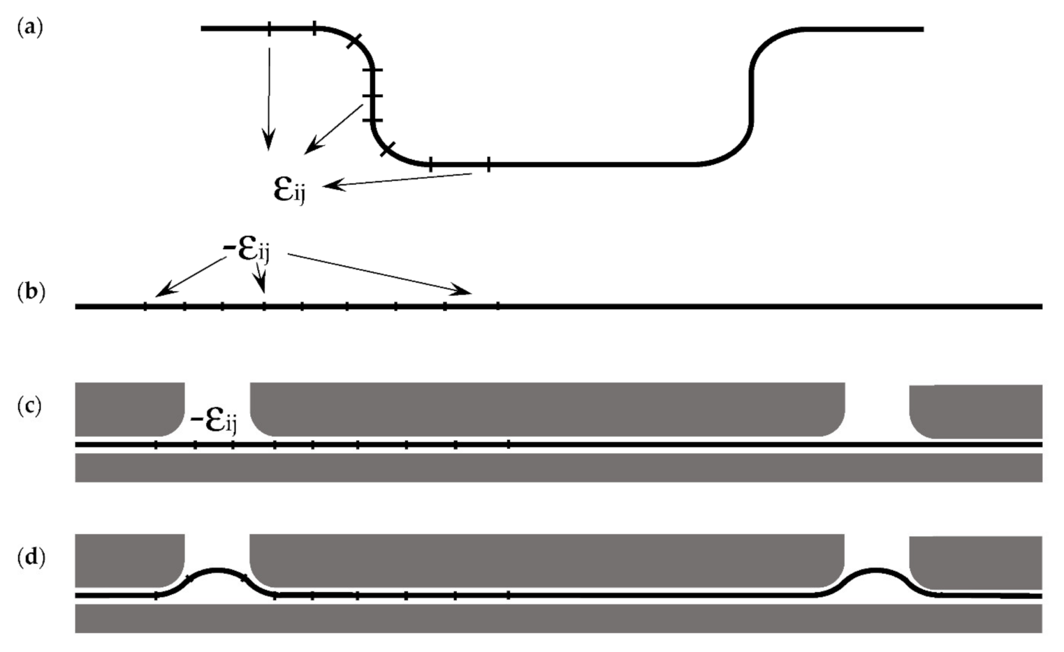
The forming process was simulated based upon uniformly distributed pressure, as described in step 1 of the overall methodology. From this model, the principal strain tensor components from the mid-surface of the sheet were extracted from each element and assigned to the corresponding elements of the initial sheet metal blank with an opposite sign meaning that stretching is replaced by compression as shown in Figure 1a,b.
2.2.
The initial sheet metal blank with the same Lagrangian mesh as at the beginning of the forming process in step 2.1 was positioned between two flat rigid plates as shown in Figure 1c. One of the plates had windows in which the strained sheet could bulge out. These windows were positioned above the elements which were insufficiently stretched in the initial forming process and could tolerate more deformation safely. Selection of the size and position of the windows was defined by the iterations, but the model was providing the depth of bulging in each selected window opening.
2.3.
The deformation process of sheet metal bulging into specified windows (as shown in Figure 1d) was simulated in an elastic membrane formulation previously described by Golovashchenko et al. [26]. This process was simulated in explicit formulation with linear viscosity, so the bulging stopped after few cycles of vibration. The shape of the bulged blank was then considered to be the die surface for the preforming operation. The elastic formulation of this model allowed to have a proper amount of material bulged into the windows. The yield stress was considered nonexistent for this step of the analysis.
2.4.
The preforming process of the defined pockets was simulated in elastoplastic formulation applying uniform pressure to bulge the flat sheet into the shape defined in step 2.3. The blank was then moved to the die, identical to step 2.1, and the forming process continued. As a result, the maximum strains are expected to be lowered approximately by half.
The software used for simulation in steps 1, 3, and 4 in this Chapter was LS-DYNA 971 DP.

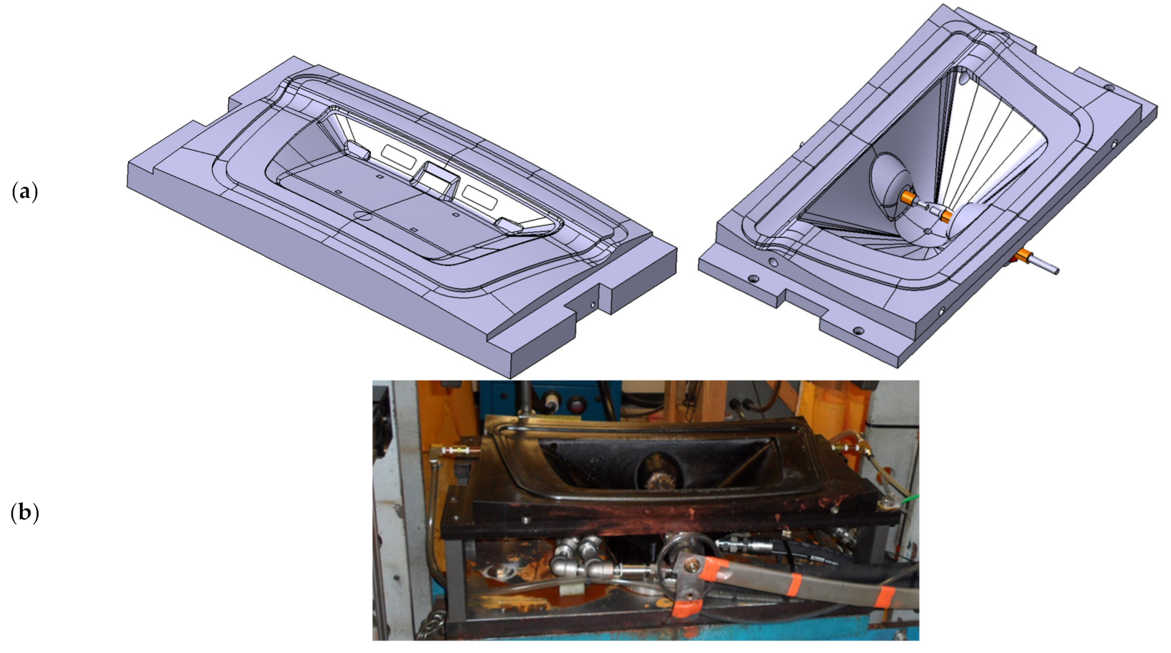
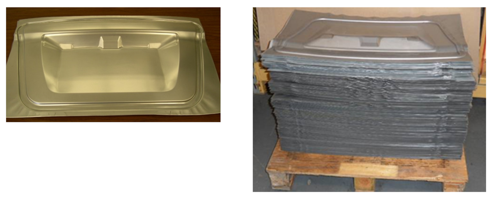
3. Case 1: Decklid Panel

3.1. Materials and Methods

The decklid panel is shown in Figure 2. The material used for this panel was an AA6111-T4 0.93 mm thick sheet.
The panel is formed using the EHF process. The perimeter of the part was initially locked by the lockbead during the binder closure. Therefore, no material inflow from outside the chamber occurred during the EHF process.
A full-scale simulation of the EHF process is a very computationally expensive tool. The most complicated and CPU-consuming part of such a model is simulating the expanding plasma bubble and simulating a water stream that moves the deformable metal sheet. Therefore, the major factor in time-saving will be eliminating one or more of these objects from consideration.
A feasibility study for the part would include the following tasks:
  • Identify the areas of the part that are most difficult to fill and require the largest pressure. Since the goal of the study is to develop a simplified, less computationally intensive approach, the simulation is performed assuming uniform pressure distribution. This approach allows to eliminate plasma and water from the model, which, combined, account for over 90% of the computational time. The resulting simplified model does not account for effects related to water–blank interaction, but the required result mostly depends on the blank–die interaction, so the simplification is justifiable and can be further refined during the final simulation step, where a more accurate model [36] can be employed.
The areas of the cavity which are filled last require the largest pressure. Usually it occurs at the sharp corners located at the bottom of the die cavity. The deformation of the blank in these areas is usually the largest, since the rest of the cavity is already filled, and filling of the corners is achieved by local stretching of the material. The locations of these difficult to fill cavities will indicate where to place the electrodes and, potentially, how many electrodes are needed.
2.
Analyzing the pressure distribution in the chamber and configuring the chamber design and the electrode system to provide sufficient pressure to fill the most difficult areas. This analysis can be done based on the Lagrangian model described by Mamutov et al. [36] where only a hydrodynamic model is used without accounting for blank deformation. It should be admitted that the duration of the process at the final discharge where almost all the cavity is filled is much shorter compared to the initial forming step where large deflections of the blank take place. It also allows the usage of Lagrangian approach vs the more computationally expensive Arbitrary Lagrangian–Eulerian (ALE) approach.
This simplified model allows for virtual movement of the electrodes at the simulation stage and modification of the shape of the chamber to provide sufficient pressure to fill the sharp corners in all necessary areas of the part.
3.
Conduct a formability study based on numerical or experimental verification of the decisions made in the previous two steps. During this step, the available data on pulse forming formability should be reviewed as well as expected loads on the die and on the electrode system.
4.
Perform the analysis to clarify whether a preforming step enabling the redistribution of the peak strains in a formed part is needed.
The simulation software used for all other numerical models was LS-DYNA 971 DP.

3.2. Results and Discussion

The strain distribution in the formed panel at the end of the simplified uniform pressure analysis is shown in Figure 3. The symmetry along the cross-section A-A was taken into account, so only the half of the panel was simulated. The results of numerical simulation indicated that the styling lines with sharper radii do not represent a problem, since the material can be pulled from the adjacent areas of the blank. The area of deep drawing and sharp corners shown in red and yellow in Figure 3 represent a problem from both the required pressure and formability perspectives. Similar results were received from a more detailed numerical model [36] where all the details of pulsed pressure propagation through the water filled chamber as well as dynamic deformation of the blank were taken into account: the corners shown in red were filled last and required higher voltage discharges to be completed. The quantitative comparison of simulation results using the simplified approach and the model [36] in the area of maximum strains in Figure 3 indicated that the simplified approach gives slightly higher strains in the area of corners: 0.25 major principal strain vs. 0.22 in the simulation using method [36]. It should be admitted, however, that in [36], the ALE Method was employed while in this study, the traditional Lagrangian mesh was used. It should be indicated that in both numerical models, friction was accounted for based upon Coulomb’s friction law using a constant coefficient of friction. In real forming conditions, the coefficient of friction may vary significantly depending on contact pressure and the possibility to squeeze the lubricant from the contact between the sheet and the die. This factor alone might lead to more significant uncertainty in major strains than the difference between the results obtained by both methods.
One of the major drawbacks of using the full-scale simulation approach described in [36] is significant hardware and CPU-time demand. This issue exists on multiple levels. First of all, the approach [36] requires simulation of the discharge channel, pressure transmitting water, and the sheet being deformed in contact with the die. The computational effort to simulate pressure propagation through the fluid takes over 90% of the computational time.
Second, the contact between the water and the sheet metal requires correlation between the element sizes of water and blank meshes: the Fluid Structure Interaction algorithm in LS-DYNA dictates that they must be about the same size. This leads to a cubic-power growth of the number of fluid elements with the refinement of sheet metal elements. As a result, even when using powerful cluster computers, the user has to select element size based not on the desired mesh size, but based on the available hardware resources.
Third, a typical EHF process is a multidischarge process, which means that three to four such simulations must be performed correlating to the actual number of performed EHF discharges in order to simulate a full forming process of a panel. One additional complication related to this is the need to prepare the models and transfer simulation data while simulating sequential discharges.
Comparison of required computations could be done based upon the following example: to simulate the EHF process in [36], 8–10 h of computation on a powerful cluster machine with 32 processors was required for each discharge. It required multiple days of simulation with just a small improvement in mesh quality.
Even though the growth of CPU power and available memory as well as software development will make the full scale approach eventually available for an engineer working on the design of sheet metal forming processes, it is still difficult to use the approach [36] outside of research facilities. Alternatively, using the simplified approach presented in this paper only requires a desktop PC and much shorter simulation time of under one hour, which opens the possibility to analyze multiple configurations of the EHF forming process and make practical design decisions.
Figure 4 shows the blank formed by quasistatic hydroforming with 2.1 MPa pressure of the fluid. The clamping force was provided by a 100 ton hydraulic Dake Dura press. It can be seen that the overall cavity is filled except the corners. This simplified analysis indicated that approximately 30 MPa of pressure is needed to fill the sharp corners. Taking into account the full area of the panel where the quasistatic pressure is applied, the maximum affordable pressure for a 100-ton clamping force is approximately 3 MPa. To form this panel quasistatically, a factor-of-10 larger clamping press would be needed. The next step is to design a chamber which can deliver this level of pulsed pressure using available energy from an existing pulse generator.
An example of such analysis for the part shown in Figure 2 is illustrated in Figure 5. Due to the limitations of the Lagrangian approach used in this simulation, the shape of the chamber is slightly simplified, and the shape of the electrodes is not taken into account. Since the volume of the electrodes is significantly smaller than the overall volume of the chamber, the introduced numerical error is negligible.
Based on this analysis, it was concluded that a single electrode chamber design is capable of providing the required pressure. The next step is to optimize the position of the electrodes and the size of the chamber using a purely hydrodynamic model. By minimizing the volume of the chamber, higher pressure can be accomplished from a very simple and approximate consideration that the energy of water compression can be understood as an integral of pressure by volume: a smaller volume of the chamber with the same level of discharged energy will result in a higher average pressure in the chamber.
At the initial stage of formulating the chamber design, the general considerations that the propagation of a shock wave initially has spherical symmetry, as it was admitted in early publications on the hydrodynamic analysis of explosions, for example by Cole [31], until the wave contacts the walls of the chamber, and reflections from the walls start influencing the pressure distribution. Therefore, positioning the electrodes closer to the most difficult to form locations might help to improve the efficiency of the chamber by utilizing the energy of the initial shock wave as well as minimizing the overall volume of the chamber. However, one important limitation needs to be taken into consideration: the initial position of the sheet metal blank in the chamber should be at a distance sufficient enough to avoid arcing on the blank. For the prototype conditions, in addition to just increasing the distance from the electrodes to the sheet metal blank, the conductive wire can be placed between the electrodes for the first discharge.
Alternatively, a moveable electrode head proposed by Golovashchenko [29] can be used to keep the volume of the chamber small and have a capability to adjust the distance between the discharge channel and the blank at each following discharge. The resulting die and the chamber design for making the part is shown in Figure 6a,b.
The next step in the proposed algorithm is formability analysis. Making a decision based upon a traditional Forming Limit Diagram (FLD) and simulation results is safe but might be too conservative. As indicated in Figure 3, the major strain in the corner filling operation was 0.25 with approximately the same level of minor strain. Based upon formability studies performed by Graf and Hosford [45] and Chow et al. [46], the equibiaxial stretching of this level is marginal to fracture.
However, EHF brings visible improvement in formability due to high strain rate and coining effects, especially for corner filling operations, as it was discussed in multiple publications quantifying formability in pulsed forming. The existing data on formability improvement should be taken with caution, especially when applied to parts of complex geometry when multiple discharges are necessary for successful filling of the die cavity. Based upon studies of formability for AA6111-T4 and AA5754 by Imbert et al. [16], AA5182 by Rohatghi et al. [17], and steels DP500, DP600, DP780, and DP980 by Golovashchenko et al. [19], a relative formability improvement of 50% is achievable. A higher percentage of improvement could be achieved with higher energies and higher forming velocities in exchange for a risk of damaging the die, especially if a low cost die material were used for prototype applications. The experimental results published by Golovashchenko et al. [47] indicated that this panel is safe to form with EHF. Therefore, no preforming step was necessary.
The tryout experiments for the part illustrated in Figure 2 were performed successfully employing an EHF chamber with 11 liters of volume. The air from the described chamber between the blank and the water as well as from the area between the sheet and the surface of the die was removed before starting the EHF process. In order to minimize impact loading on the surface of the die and extend the life of the electrodes, the EHF forming process was done in three discharges of 8 kV, 9 kV, and 13 kV using a Magnepress pulse generator which had 200 μF capacitance and 200 nH internal inductance. The process started from closing the binder followed by air evacuation from the chamber and from the die. The next step was EHF forming itself, which included three discharges. In order to estimate forming results without opening the die, the amount of water added to the chamber was measured experimentally. After the last discharge, the amount of added water was approximately 20 mL to compensate for the displacement of the blank towards the die cavity. This indicated that the process was successfully completed. At the tryout stage, an extra discharge of 13 kV was performed with nearly no water added to the chamber. The formed parts from AA6111-T4 material of 0.93 mm thickness are shown in Figure 7. For this application, no preforming step is needed.

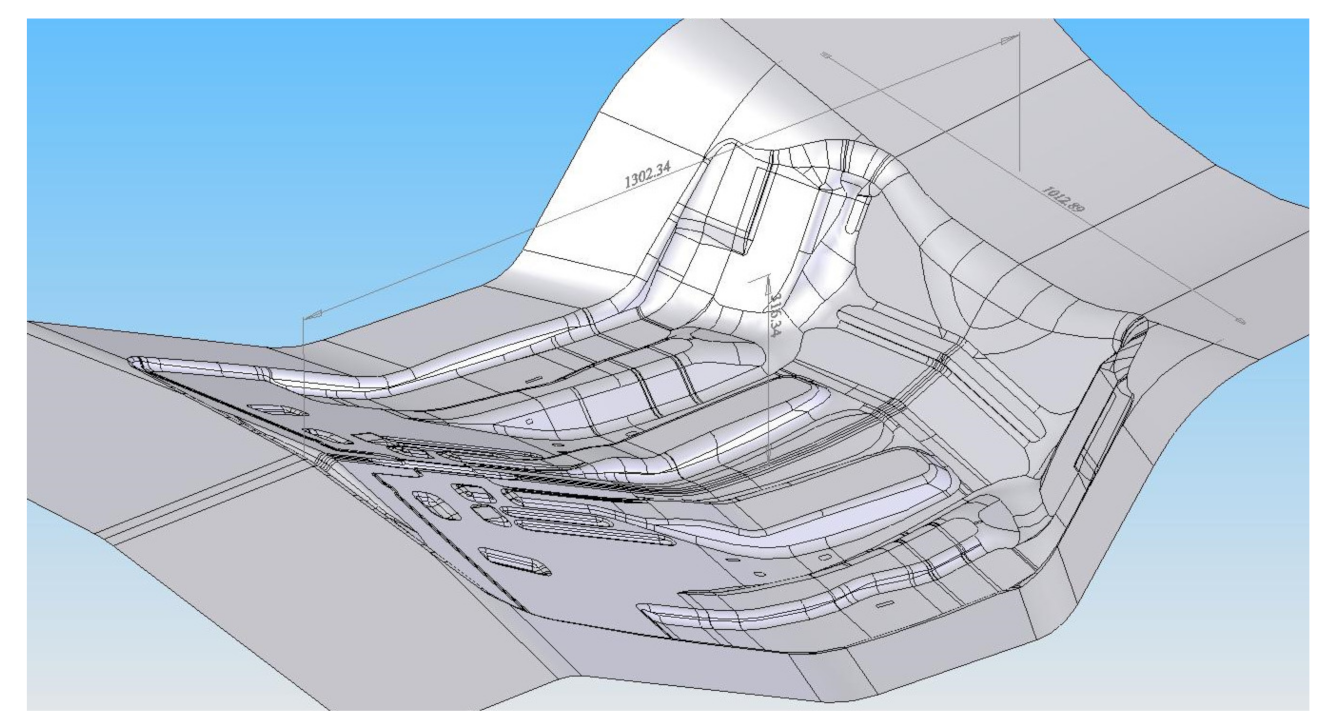
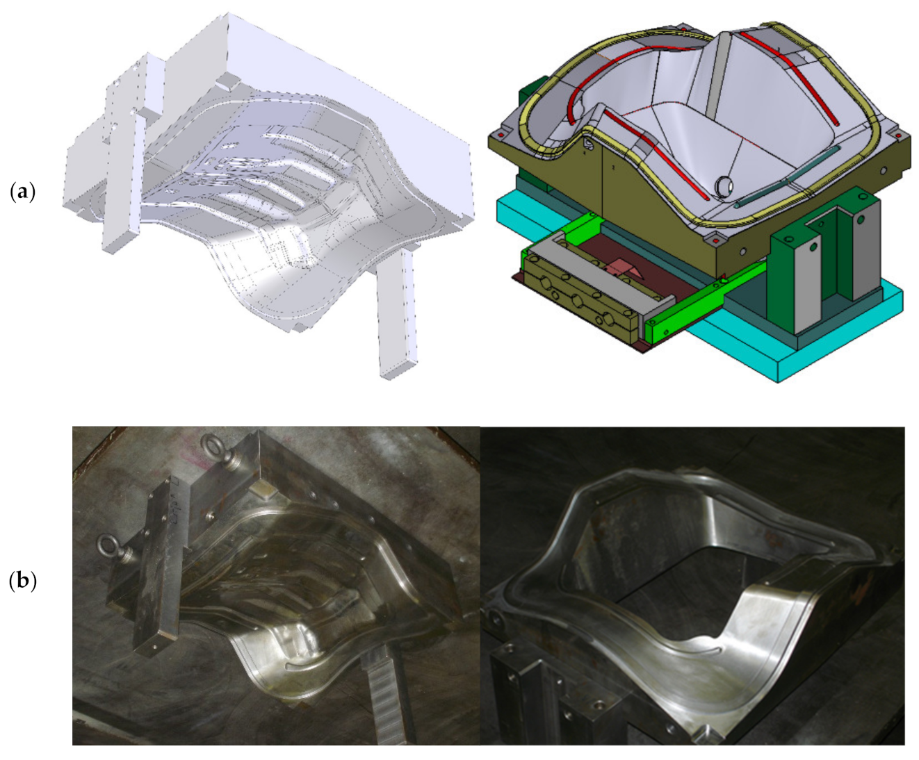
4. Case 2: Complex Automotive Panel

4.1. Materials and Methods

In order to demonstrate another possible scenario to form a prototype part, a part with deep local cavities but relatively dull radii is illustrated in Figure 8.
The die and the chamber design for making the part is shown in Figure 9a,b.
This part has multiple channels and a deep cavity with curvatures of the flange in two directions. This part was formed as a prototype in 40% scale: every dimension was reduced by a factor of 2.5. The in-plane dimensions of the EHF formed part were 521 mm (instead of 1302) × 448 mm (instead of 1012 mm), and the maximum depth of the cavity was 126 mm (instead of 315 mm). The sheet material used for this prototype process was 0.55 mm DP500 steel. The experimental results on sheet metal behavior at high strain rates for numerical simulation were taken from the study by Baumer et al. [48], and the experimental results on formability of DP500 were used from the experimental work by Golovashchenko et al. [19].

4.2. Results and Discussion

To reduce the simulation computational costs and speed-up the design process, the simulation was performed using a simplified approach. Instead of using a costly full-scale approach, which included simulating the discharge channel, water, and blank deforming at high velocity, a simplified approach was used such that the blank was deformed by uniform pressure. The result of such a simulation is shown in Figure 10.
Some material inflow was observed during the forming process which helped to form the peripheral channels. The maximum strain in the simulation was observed in the central elongated channel with a true strain of 1.21. In this case, the benefits of extended formability would not be sufficient. A split in the blank was predicted in the form of a strain localization in simulation results in Figure 10. This split was observed in experimental tryout shown in Figure 11, which confirmed the original expectations. Please note that even though the simulation was performed in simplified form, it was able to predict this split and its location.
In this case a solution to the split issue was to introduce the preforming operation in which the material is bulged in the areas of low strain to provide additional metal inflow to the areas of high strain, as suggested by Golovashchenko [43]. In order to define where these pockets should be, the principal strains of the mid-surface of the sheet obtained from the initial numerical simulation were numerically imposed as the initial condition in the initial mesh of the flat blank with opposite signs. In other words, since the strains of the mid surface of the formed part were always tensile, they were imposed into the initial flat blank as compressive strains, which led to compressive elastic stresses in the flat sheet restrained between the two rigid plates.
At this stage the sheet was assumed to be purely elastic, similar to the approach earlier suggested by Golovashchenko et al. [26]. The blank was fully clamped at the edges between the two flat rigid plates. In order to identify the necessary pockets and their depth, the cavities on the upper flat plate were open in specified areas of the flat blank, allowing the material to bulge. These specified areas were selected in the groups of elements which would experience low strain in the formed final shape, but being adjacent to the areas of the flat blank which would experience high strain during forming of the targeted shape. These boundary conditions permitted only in-plane displacement of the areas corresponding to high strain and free flow into the open windows where the strain was low.
Driven by elastic compressive internal stresses, the sheet was bulged into these open cavities. The depth of bulging was defined by the level of internal compressive stresses assigned to each element of the mesh in accordance with the amount of strain the material received during the forming step. Overall, this process had multiple iterations and multiple bulged cavities were observed and analyzed.
At the next step, the initial flat blank was formed into the designed pockets in a traditional elasto-plastic formulation which led to stretching in the areas of otherwise low strain. This preformed blank then was virtually placed in a simplified model of the EHF process where uniform pressure was applied to the preformed blank, and the deformation process of EHF forming into the shape shown in Figure 9 was further continued. During the forming of prebulged blanks, the material would flow from the preformed pockets to the areas of higher strain lowering the maximum level of strain. The strain distribution was analyzed from the perspective of peak strain. The best configuration, which had the minimum peak strain, was selected for the experimental validation.
The most successful pockets configuration is shown in Figure 12. The pockets were formed with flexform process using a one sided tool. They also could be formed through an EHF process.
One can note that the maximum strain of 0.7 shown by the simplified simulation approach is significantly less than in the configuration without preforming pockets, but is still larger than that realistically achievable in a typical forming process. The purpose of this simulation was not to achieve formable conditions in the simulation result but rather to find the way to reduce the final strain. The ultimate feasibility in this case was proven experimentally. As a result of introducing the preforming step, the part was formed without splits using the same die and chamber design shown in Figure 9a,b. The successful panel was formed using a Magnepress pulse generator with the following sequence of nine discharges: 9 kV, 9 kV, 10 kV, 11 kV, 12 kV, 13 kV, 14 kV, 14.5 kV, and 14.5 kV. The last discharge was to confirm that the blank is fully formed, and no more water is added to the EHF chamber. Forming blanks with multiple discharges permits the forming of more complex parts and avoid fracture due to reduced friction: when the blank moves in several steps with unloading, the local areas of metal-to-metal contact typically leading to increases in friction are getting separated. This effect needs more thorough study in future work.
The results of simulation using the same simplified approach are shown in Figure 13.
This study validated another advantage of EHF technology: due to “soft” applications of pressure, the blank can have pockets of material which enable redistribution of strain in sheet metal by allowing an easier flow of material from the pockets to heavily strained areas. By tracking the heavily strained elements and low strained elements, the areas of high strain and low strain can be projected on the initial blank. In this case, the pockets can be formed on the flat blank which make the preforming die simple and inexpensive. A preforming step with a very shallow preform can be added to the process if a traditional EHF approach does not provide sufficient formability to successfully form the part. A similar effect is difficult to achieve in a conventional die set, because the rigid upper die tends to crush pockets before they can spread.

5. Conclusions

  • Based upon performed demonstrations, the electrohydraulic forming process is a viable technology for prototype and low volume production of sheet metal components formed from flat sheets.
  • A simplified simulation based on quasistatic forming of the blank under uniformly distributed pressure helps to identify critical areas of the part. Such a simulation is significantly less computationally-demanding than a full-scale model, yet is able to provide information about potential splits and difficult to form areas. This simplified approach helps to understand which areas of the die are filled last and require the highest pressure, which enables designing the EHF chamber in a way that sufficient pressure would be provided, to make decisions on electrodes configuration, and also makes preforming analysis possible.
  • A simplified simulation based on a purely hydrodynamic model, which does not include the blank, helps to analyze pressure distribution at the last discharge and enables optimization of the chamber’s shape and volume.
  • Preforming sheet metal blanks in order to redistribute the strains involving areas of low strain is a low cost additional process, which can help if insufficient formability occurs in local areas of the formed blank.

Author Contributions

Conceptualization, methodology, validation, investigation, A.V.M., S.F.G., N.M.B. and V.S.M.; software, formal analysis, A.V.M.; resources, data curation, S.F.G.; writing—original draft preparation, writing—review and editing, A.V.M. and S.F.G.; visualization, A.V.M.; supervision, project administration, and funding acquisition, S.F.G. All authors have read and agreed to the published version of the manuscript.

Funding

This material is based upon work supported by the Advanced Manufacturing Office of the United States Department of Energy under Award Number DE-FG36-08GO18128 and Ford Research and Advanced Engineering.

Institutional Review Board Statement

Not applicable.

Informed Consent Statement

Not applicable.

Data Availability Statement

Data is contained within the article.

Acknowledgments

Authors would like to acknowledge Andrey Ilinich and Georgji Demirasi for their contribution at the initial stage of the project.

Conflicts of Interest

The authors declare no conflict of interest. The funders had no role in the design of the study; in the collection, analyses or interpretation of data; in the writing of the manuscript or in the decision to publish the results.

References

  1. Ferreira, C.d.S.; Kaminski, P.C. Global Vehicle Architectures Development in the Automotive Industry. SAE Tech. Pap. Ser. 2007, 1, 2575. [Google Scholar] [CrossRef]
  2. Lange, K. Handbook of Metal Forming; McGraw-Hill Book company: New York, NY, USA, 1985; pp. 27.1–30.11. [Google Scholar]
  3. Wilson, F.W. High-Velocity Forming of Metals; Prentice-Hall Inc.: Englewood Cliffs, NJ, USA, 1964. [Google Scholar]
  4. Altan, T.; Tekkaya, A.E. Sheet Metal Forming: Processes and Applications; ASM International: Materials Park, OH, USA, 2012; pp. 160–167. [Google Scholar]
  5. Bruno, E.J. High-Velocity Forming of Metals. American Society of Tool and Manufacturing Engineers; Prentice Hall, Inc.: Dearborn, MI, USA, 1964. [Google Scholar]
  6. Davies, R.; Austin, E.R. Development in High Speed Metal Forming; Industrial Press Inc.: New York, NY, USA, 1970. [Google Scholar]
  7. Callender, E.M. Electric Hydroforming by Wire Vaporization. In Proceedings of “Advanced High Energy Rate Forming”, Creative Manufacturing Seminars; ASME: Detroit, MI, USA, 1961–1962; paper SP62–81; pp. 1–21. [Google Scholar]
  8. Felts, R. Application of Electrohydraulic Effect to Metal Forming. In Proceedings of “Advanced High Energy Rate Forming”, Creative Manufacturing Seminars; ASME: Detroit, MI, USA, 1961–1962; paper SP62–08; pp. 1–10. [Google Scholar]
  9. Hanley, F. High Energy Rate Forming at General Dynamics/Fort Worth. In Proceedings of “Advanced High Energy Rate Forming”, Creative Manufacturing Seminars; ASME: Detroit, MI, USA, 1961–1962; paper SP62–15; pp. 1–22. [Google Scholar]
  10. Feddersen, E.W. Electrohydraulic Process of High Energy Rate Forming. In Proceedings of “Advanced High Energy Rate Forming”, Creative Manufacturing Seminars; ASME: Detroit, MI, USA, 1961–1962; paper SP60–164; pp. 1–9. [Google Scholar]
  11. Schrom, E.C. Metal Forming with Capacitor Discharge Electro-Spark. In Proceedings of “Advanced High Energy Rate Forming”, Creative Manufacturing Seminars; ASME: Detroit, MI, USA, 1961–1962; paper SP62–80; pp. 1–9. [Google Scholar]
  12. Duncan, J.L.; Johnson, W. Electrohydraulic Forming. In Proceedings of the NATO Seminar “High Rate Working of Metals”, Sandefjord, Norway, 24–25 September 1964; pp. 107–118. [Google Scholar]
  13. Keeler, S.P. Determination of Forming Limits in Automotive Stampings. SAE Tech. Pap. Ser. 1965, 1–9. [Google Scholar] [CrossRef]
  14. Goodwin, G.M. Application of Strain Analysis to Sheet Metal Forming Problems in the Press Shop. SAE Tech. Pap. Ser. 1968, 1968, 1–8. [Google Scholar] [CrossRef]
  15. Balanethiram, V.; Daehn, G.S. Hyperplasticity: Increased forming limits at high workpiece velocity. Scr. Met. Mater. 1994, 30, 515–520. [Google Scholar] [CrossRef]
  16. Imbert, J.M.; Winkler, S.L.; Worswick, M.J.; Oliveira, D.A.; Golovashchenko, S.F. The effect of tool-sheet interac-tion on damage evolution in electromagnetic forming of aluminum alloy sheet. J. Eng. Mater. Technol. 2005, 127, 145–153. [Google Scholar] [CrossRef]
  17. Rohatgi, A.; Soulami, A.; Stephens, E.V.; Davies, R.W.; Smith, M.T. An investigation of enhanced formability in AA5182-O Al during high-rate free-forming at room-temperature: Quantification of deformation history. J. Mater. Process. Technol. 2014, 214, 722–732. [Google Scholar] [CrossRef]
  18. Dariani, B.M.; Liaghat, G.H.; Gerdooei, M. Experimental investigation of sheet metal formability under various strain rates. Proceedings of the Institution of Mechanical Engineers. J. Eng. Manuf. 2009, 223, 703–712. [Google Scholar] [CrossRef]
  19. Golovashchenko, S.F.; Gillard, A.J.; Mamutov, A.V. Formability of dual phase steels in electrohydraulic forming. J. Mater. Process. Technol. 2013, 213, 1191–1212. [Google Scholar] [CrossRef]
  20. Samei, J.; Green, D.E.; Golovashchenko, S.; Hassannejadasl, A. Quantitative Analysis of Microstructure Defor-mation Improvement in Dual Phase Steels Subject to Electrohydraulic Forming. J. Mater. Eng. Perform. 2012, 22, 2080–2088. [Google Scholar] [CrossRef]
  21. Jenab, A.; Green, D.; Alpas, A. Microscopic investigation of failure mechanisms in AA5182-O sheets subjected to elec-tro-hydraulic forming. Mater. Sci. Eng. A 2017, 691, 31–41. [Google Scholar] [CrossRef]
  22. Mynors, D.; Zhang, B. Applications and capabilities of explosive forming. J. Mater. Process. Technol. 2002, 125–126, 1–25. [Google Scholar] [CrossRef]
  23. Psyk, V.; Risch, D.; Kinsey, B.L.; Tekkaya, A.E.; Kleiner, M. Electromagnetic forming–A review. J. Mater. Process. Technol. 2011, 211, 787–829. [Google Scholar] [CrossRef]
  24. Maris, C.; Hassannejadasl, A.; Green, D.E.; Cheng, J.; Golovashchenko, S.F.; Gillard, A.J.; Liang, Y. Comparison of quasi-static and electrohydraulic free forming limits for DP600 and AA5182 sheets. J. Mater. Process. Technol. 2016, 235, 206–219. [Google Scholar] [CrossRef]
  25. Cheng, J.; Green, D.E.; Golovashchenko, S.F. Formability enhancement of DP600 steel sheets in electro-hydraulic die forming. J. Mater. Process. Technol. 2017, 244, 178–189. [Google Scholar] [CrossRef]
  26. Golovashchenko, S.F.; Bessonov, N.M.; Ilinich, A.M. Two-step method of forming complex shapes from sheet metal. J. Mater. Process. Technol. 2011, 211, 875–885. [Google Scholar] [CrossRef]
  27. Homberg, W.; Beerwald, C.; Probsting, A. Investigation of the Electrohydraulic Forming Process with Respect to the Design of Sharp Edged Contours. In Proceedings of the 4th International Conference on High Speed Forming, Columbus, OH, USA, 9–10 March 2010; pp. 58–64. [Google Scholar]
  28. Singh, H. Fundamentals of Hydroforming; Society of Manufacturing Engineers: Dearborn, MI, USA, 2003; pp. 29–35. [Google Scholar]
  29. Golovashchenko, S.F. Electrohydraulic Forming Process with Electrodes that Advance within a Fluid Chamber towards a Workpiece. U.S. Patent 8,844,331B2, 30 September 2014. [Google Scholar]
  30. Vagin, V.A.; Zdor, G.N.; Mamutov, V.S. Methods of Research of High-Speed Deformation of Metals; Nauka I Technika: Minsk, Belarus, 1990. (In Russian) [Google Scholar]
  31. Cole, R.H.; Weller, R. Underwater Explosions. Phys. Today 1948, 1, 35. [Google Scholar] [CrossRef]
  32. Knyazev, M.K.; Zhovnovatuk, Y.S. Measurements of Pressure Fields with Multi-Point Membrane Gauges at Elec-Trohydraulic Forming. In Proceedings of the 4th International Conference on High Speed Forming, Columbus, OH, USA, 9–10 March 2010; pp. 75–82. [Google Scholar]
  33. Melander, A.; Delic, A.; Bjorkblad, A.; Juntunen, P.; Samek, L.; Vadillo, L. Modelling of electrohydraulic free and die forming of sheet steels. Int. J. Mater. Form. 2013, 6, 223–231. [Google Scholar] [CrossRef]
  34. Hassannejadasl, A.; Green, D.E.; Golovashchenko, S.F.; Samei, J.; Maris, C. Numerical Modeling of Electrohydrau-lic Free-Forming and Die-Forming of DP590 steel. J. Manuf. Process. 2014, 16, 391–404. [Google Scholar] [CrossRef]
  35. Vohnout, V.J.; Fenton, G.; Daehn, G.S. Pressure heterogeneity in small displacement electrohydraulic forming process. In Proceedings of the 4th International Conference on High Speed Forming, Columbus, OH, USA, 9–10 March 2010; pp. 65–74. [Google Scholar]
  36. Mamutov, A.V.; Golovashchenko, S.F.; Mamutov, V.S.; Bonnen, J.J. Modeling of electrohydraulic forming of sheet metal parts. J. Mater. Process. Technol. 2015, 219, 84–100. [Google Scholar] [CrossRef] [Green Version]
  37. Woo, M.; Lee, K.; Song, W.; Kang, B.; Kim, J. Numerical Estimation of Material Properties in the Electrohydraulic Forming Process Based on a Kriging Surrogate Model. Math. Probl. Eng. 2020, 2020, 1–12. [Google Scholar] [CrossRef]
  38. Jenab, A.; Green, D.E.; Alpas, A.T.; Golovashchenko, S.F. Experimental and numerical analyses of formability im-provement of AA5182-O sheet during electro-hydraulic forming. J. Mater. Process. Technol. 2018, 255, 914–926. [Google Scholar] [CrossRef]
  39. Woo, M.; Song, W.-J.; Kang, B.-S.; Kim, J. Evaluation of formability enhancement of aluminum alloy sheet in elec-trohydraulic forming process with free-bulge die. Int. J. Adv. Manuf. Technol. 2019, 101, 1085–1093. [Google Scholar] [CrossRef]
  40. Zhang, F.; Zhang, J.; He, K.; Hang, Z. Application of Electro-hydraulic Forming (EHF) Process with Simple Dies in Sheet Metal Forming. In Proceeding of the International Conference on Information and Automation, Wuyi Mountain, China, 11–13 August 2018; pp. 401–405. [Google Scholar]
  41. Xiong, L.; Liu, Y.; Yuan, W.; Huang, S.; Li, H.; Lin, F.; Pan, Y.; Ren, Y. Cyclic shock damage characteristics of electrohydraulic discharge shockwaves. J. Phys. D Appl. Phys. 2020, 53, 185502. [Google Scholar] [CrossRef]
  42. Daehn, G.S.; Vohnout, V.J.; Dubois, L. Improved Formability with Electro-Magnetic Forming: Fundamentals and Practical Example. In Proceedings of the TMS Symposium “Sheet Metal Forming Technology”, San-Diego, CA, USA, 28 February–4 March 1999; Demeri, M.Y., Ed.; pp. 105–115. [Google Scholar]
  43. Golovashchenko, S.F. Method and Apparatus for Making a Part by First Forming an Intermediate Part that Has Donor Pockets in Predicted Low Strain Areas Adjacent to Predicted High Strain Areas. U.S. Patent 9,522,419B2, 20 December 2016. [Google Scholar]
  44. Chen, X.; Hsiung, C.-K.; Schmid, K.; Du, C.; Zhou, D.; Roman, C. Evaluation of Metal Gainers for Advanced High Strength Steel Flanging. SAE Tech. Pap. Ser. 2014. [Google Scholar] [CrossRef]
  45. Graf, A.; Hosford, W. The influence of strain-path changes on forming limit diagrams of AL 6111 T4. Int. J. Mech. Sci. 1994, 36, 897–910. [Google Scholar] [CrossRef] [Green Version]
  46. Chow, C.; Yu, L.; Tai, W.; Demeri, M. Prediction of forming limit diagrams for AL6111-T4 under non-proportional loading. Int. J. Mech. Sci. 2001, 43, 471–486. [Google Scholar] [CrossRef]
  47. Golovashchenko, S.F.; Mamutov, V.S.; Dmitriev, V.V.; Sherman, A.M. Formability of Sheet Metal with Pulsed Electromagnetic and Electrohydraulic Technologies. In Proceedings of the TMS symposium “Aluminum-2003”, San-Diego, CA, USA, 2–6 March 2003; pp. 99–110. [Google Scholar]
  48. Bäumer, A.; Jiménez, J.A.; Cugy, P. Investigation of the Strain-Hardening Behavior of Modern Lightweight Steels Considering the Forming Temperature and Forming Rate; Directorate-General for Research and Innovation, European Commission: Brussel, Belgium, 2004; pp. 78, 90. [Google Scholar]
Figure 1. Schematic illustrating the steps of building a preforming shape: (a)—simulation of forming under uniform pressure, (b)—applying the obtained opposite sign field of strains to the initial flat blank, (c)—placing the prestressed blank within the restraining shape, (d)—identifying the preforming geometry by simulating the bulging process.
Jmmp 05 00047 g001
Figure 2. Design of the part formed by EHF.
Jmmp 05 00047 g002
Figure 3. Results of quasistatic numerical simulation of forming a sheet metal blank with uniformly distributed pressure.
Jmmp 05 00047 g003
Figure 4. Aluminum 6111-T4 panel formed by quasistatic hydroforming using 2.1 MPa of pressure.
Jmmp 05 00047 g004
Figure 5. Distribution of pressure in the EHF chamber along the cross-section A-A for the last discharge when the die cavity is completely filled with the blank.
Jmmp 05 00047 g005
Figure 6. Design of the die-chamber tool set (a), and experimental chamber (b).
Jmmp 05 00047 g006
Figure 7. EHF formed prototype part from Aluminum Alloy 6111-T4.
Jmmp 05 00047 g007
Figure 8. Design of the part for the prototype process.
Jmmp 05 00047 g008
Figure 9. Die and chamber design (a), and fabricated die and chamber (b).
Jmmp 05 00047 g009
Figure 10. Results of numerical simulation based upon the assumption of uniformly distributed pressure. Maximum strain is 1.21.
Jmmp 05 00047 g010
Figure 11. EHF formed part with splits in the areas of maximum strain.
Jmmp 05 00047 g011
Figure 12. Preform shape.
Jmmp 05 00047 g012
Figure 13. Simulation of two-step forming process: (a) preforming step, maximum strain is 0.213; (b) fully formed part, maximum strain is 0.7.
Jmmp 05 00047 g013
Publisher’s Note: MDPI stays neutral with regard to jurisdictional claims in published maps and institutional affiliations.

