Article

Passive Chatter Suppression of Thin-Walled Parts by Means of High-Damping Lattice Structures Obtained from Selective Laser Melting

Polytechnic Department of Engineering and Architecture, University of Udine, Via Delle Scienze 206, 33100 Udine, Italy
*
Author to whom correspondence should be addressed.
J. Manuf. Mater. Process. 2020, 4(4), 117; https://doi.org/10.3390/jmmp4040117
Submission received: 25 November 2020 / Revised: 6 December 2020 / Accepted: 7 December 2020 / Published: 10 December 2020
(This article belongs to the Special Issue Machine Tool Dynamics)

Abstract

:
Chatter vibrations arising during machining operations are detrimental for cutting process performance, since they may cause poor surface quality of the machined part and severe damages to machine tool elements. Passive approaches for chatter suppression are based on the integration of special mechanical components with high-damping properties within the machining system. They represent a good solution to this problem thanks to their intrinsic simplicity. Recently, the application of metallic lattice structures inside 3D printed parts obtained from the Selective Laser Melting technology have proven superior damping properties with respect to the same full density material. Here, this idea is further explored by considering the novel configuration where the unmelted powder grains are retained inside the lattice structure by an external shell, acting as a multiplicity of microscopic mechanical dampers. This concept is applied for passive chatter suppression of thin-walled parts that are of particular relevance for industry. Preliminary experimental investigation was first carried out on simple beam-like specimens, and then on thin-walled benchmarks that were identified through modal analysis and tested under real cutting conditions. The main conclusion is that the novel proposed configuration (lattice plus unmelted powder) has higher damping properties with respect to the full density and lattice alternatives. Accordingly, it may be successfully applied for passive chatter suppression in real machining operations.

1. Introduction

Milling operations of thin-walled geometries, typical of slender parts like compressor and turbine blades, require particular attention. Unstable phenomena that often manifest in the form of self-excited vibrations are easily triggered by the low bending stiffness of thin-walled parts.
Regenerative chatter vibrations can cause undesired surface undulations/marks, accelerated tool wear, and severe mechanical failures of machine tool elements such as the spindle bearings.
Therefore, avoidance of cutting process instabilities is fundamental for successfully performing industrial machining operations on slender parts [1,2].
When adopting preventive-predictive strategies, the so-called stability lobe diagrams (SLD) are determined through the stability analysis of a set of Delay Differential Equations (DDEs) representing milling dynamics linearized around a given stable, T-periodic (where T is the spindle revolution period) relative motion between tool tip and workpiece. Nowadays, the most common methods for carrying out this difficult task are the Multi-Frequency Method (MFM) [3]), the Semi-Discretization Method (SDM) [4], the Full-Discretization variants (FDM) (e.g., see [5]), the Improved Chebyshev Collocation Method [6,7], and others.
Nevertheless, this approach requires a preliminary, accurate identification of the modal parameters of the machining system, which is not always feasible in industrial environments. In addition, the dynamic behavior of slender parts depends on many unknown factors, and it can vary due to the material removal process. Process damping [8] or rapid tool wear [9] may further hinder the application of predictive strategies.
To overcome the disadvantages of process parameters optimization by means of SLD, it is possible to apply semi-active, active or passive chatter suppression techniques.
Tuned mass dampers (TMDs) can be considered semi-active devices that suppress mechanical vibrations by introducing a properly tuned antiresonance close to the original system resonance. In the last decade, special TMDs were developed for an efficient chatter suppression, such as multiple TMDs [10], self-tunable TMDs, and variable stiffness TMDs [11,12].
However, TMDs may interfere with the machine tool elements, they may reduce the available working space, and they may be ineffective when machining system dynamic properties vary considerably. Thus, their application is justified only for specific applications [9].
Alternatively, viscous fluids can be adopted for dissipating undesired machining system vibrations. For example, Zhang et al. [13] demonstrated an effective chatter suppression by submerging the whole milling system in a viscous fluid.
Active control of machine tool vibrations through advanced actuators is another possibility. For instance, Wan et al. [14] developed a spindle system with an integrated electromagnetic actuator that achieved a satisfactory chatter suppression. Butt et al. [15] designed a two-degree-of-freedom apparatus that exploits non-contact eddy current damping to enhance process stability. Munoa et al. [9] designed a tunable clamping table for regulating mode coupling dynamics with the aim of chatter suppression in milling of thin-walled parts.
Although active control of chatter may reach outstanding results, it requires major upgrades or modifications of current machine tools, thus it is generally complex to implement in existing equipment and generally expensive.
Therefore, development of novel passive chatter suppression systems is still an interesting research topic due to their simplicity and reliability compared to active systems.
Several tools with variable pitch/variable helix [16,17] or serrated cutting edge geometries [18,19] have been developed in the last decade for passive chatter suppression. Recently, Itoh et al. [20] demonstrated that process stability can be significantly improved by means of cutter geometry optimization.
Chatter reduction can also be achieved by means of part, tool, and machine tool stiffness enhancement, for example by exploiting tailor-made fixtures designed to strengthen weaker parts (e.g., thin-walled) [21,22].
Wan et al. [23] proposed another method for increasing process stability that consisted in the application of a tensile pre-stress to the thin-walled workpiece.
In the last few years, metallic lattice structures obtained through Selective Laser Melting (SLM) have been applied for increasing the resistance to weight ratio as well as for vibrations damping in innovative mechanical components.
In detail, AlSi10Mg and AISI 316L lattices have recently showed promising damping properties in comparison with the full density reference material having the same global static stiffness [24,25].
Filling the lattice structure with polymeric materials may further enhance the capability of attenuating mechanical vibrations and reducing acoustic noise in advanced engineering applications, as it was recently illustrated in [26,27,28].
In this work, the idea of filling the lattice structure with a material that may increase the dissipation of mechanical energy was further explored. In this case, the unmelted metallic powder filling the lattice voids during the SLM process was retained within the lattice structure by means of a metallic shell. The lattice shell was 3D printed together with the lattice structure.
By doing so, the powder was densely packed and also partially melted close to the lattice beams and joints. Accordingly, powder grains were expected to act as microscopic mechanical dampers. The interaction between lattice structure and powder grains was supposed to be stronger than that obtained by filling the lattice structure with any kind of powder only after the 3D printing process.
This innovative internal configuration was tested for passive chatter suppression of thin-walled parts. This concept was experimentally studied in two phases: a first preliminary experimental campaign by using simple, beam-like specimens (already studied in [25]) and an advanced experimental campaign on thin-walled parts that were tested by performing both modal analysis and cutting tests.

2. Preliminary Experimental Campaign

2.1. Design of Experiments and Specimens Design

On the basis of the promising results obtained with AISI 316L lattice structures in [25], here the same stainless steel and specimens design were adopted. Accordingly, beam-like specimens were designed having a square cross section of 21 × 21 mm and a total axial length of 130 mm. The specimens shape was subdivided into three parts: a lower base of 30 mm axial length that was clamped by a vice, a central region of 60 mm axial length that was filled with one of the three different material configurations, and an upper base of 40 mm axial length that was hit by an impact hammer and inspected by a displacement probe during modal analysis. As done in [24,25], the dynamic bending behavior of specimens under cantilever clamping conditions was assessed by means of pulse tests that will be illustrated in the next subsection.
A cubic unit cell with FBCCZ topology, 2 mm cell size, and 0.4 mm strut diameter was chosen because it exhibited the highest damping capacity among the other cell types investigated in [25]. In addition, this lattice type was compatible with the manufacturing limits of the SLM technique [29]. The cross section geometry of the central part of the specimens was adapted in order to obtain a similar static compliance among the three tested variants: full density, lattice, and lattice plus trapped powder. The design phase consisted of iterative use of CAD/FEA tools within the SolidWorks Simulation environment.
As shown in Figure 1A, two out of four faces of the specimen lower base were constrained in order to simulate vice clamping condition. Planar symmetry was taken into account reducing FE model size by a factor of approximately two, lowering computational effort.
Hence, the static compliance was calculated as the ratio of the average displacement u to the distributed load (F = 1) applied on the small surface on the upper edge of the specimen:
G = 1 k = u F μ m N
First, resonance frequency estimation was performed with FE modal analysis considering the clamping condition mentioned before (see Figure 1B). Tetrahedral mesh optimization was carried out by means of local mesh refinement for small features or stress concentration prone locations and mesh convergence analysis.
Eventually, the cross sections illustrated in Table 1 were chosen that assured a similar static compliance among the three specimen types.
As represented in Figure 1C, a single harmonic oscillator was adopted to capture the global dynamic behavior of the system
W j ω = 1 m j ω 2 + c j ω + k = G j ω ω n , 1 2 + 2 ξ j ω ω n , 1 + 1
where m, c, and k are the modal mass, damping, and stiffness coefficients, respectively; G [μm/N] is the static compliance, ω n , 1 [rad] is the natural pulsation and ξ [ ] is the damping ratio.
Afterwards, CAD models of the specimens were exported in STL format. The manufacturing process preparation comprising STL fixing operations, positioning into the virtual build volume, supports generation, and slicing was carried out with Materialise Magics software. Beam specimens were positioned vertically in order to exploit the self supporting characteristics of FBCCZ cell topology. At the same time, this choice allowed for minimizing the layer cross section area and hence the residual thermal stresses.
The SLM manufacturing process was carried out in an inert gas atmosphere (Argon) by means of a Concept Laser M2 Cusing machine. Gas-atomized AISI 316L powders with the following chemical composition were used: 17.7% Cr, 12.9% Ni, 2.39% Mo, 1.31% Mn, 0.66% Si, 0.016% C, balance Fe. The particle size distribution (PSD) was as follows: d 10 = 19.8 μm, d 50 = 29.9 μm, d 90 = 45.1 μm. The island exposure strategy was selected while relevant SLM process parameters were set as recommended by the powder manufacturer: laser power P = 180 W, scan speed v = 600 mm/s, spot diameter d s = 120 μm, layer thickness t = 25 μm. The specimens were heat treated before separation from the build platform. The stress relieving heat treatment was set maintaining 550 °C for six hours with subsequent gradual cooling to room temperature. In order to reduce the influence of specimens positioning on the build platform and other stochastic phenomena that could affect microstructure and mechanical properties, three replicates of each specimen were produced—together with those studied in [25]—by adopting a different random distribution of specimens on each build platform. The first and second replicates are shown in Figure 2.
As shown in Figure 3, no macroscopic deformations or cracks were visible in the lattice by visual inspecting through an optical microscope. Nevertheless, inclined struts diameter was larger than expected probably due to the staircase effect, poor heat conduction typical of overhanging surfaces leading to bigger heat affected zone (HAZ) and unwanted adhesion of partially melted powders. The aforementioned phenomena were responsible for dimensional errors and lattice porosity reduction. A detailed analysis of lattice structure quality and dimensional accuracy is reported in [25].

2.2. Experimental Modal Analysis

Pulse tests were executed by clamping the lower base of each specimen by using a vice of a Haas VF-2TR CNC milling machine. The upper end of the specimen was hit by impact hammer Dytran 5800B4 (2.41 mV/N of sensitivity). Specimen vibration was measured by Micro Epsilon ES1 inductive probe, as shown in Figure 4. A Kistler 8763B triaxial accelerometer (sensitivity 50 mV/g) was attached near the specimen lower base in order to assess the influence of the vice dynamic compliance. Signals were acquired by means of National Instrument NI9215 modules with a sampling rate equal to 20 kHz and then they were elaborated within the MathWorks MATLAB environment.
As illustrated in Figure 4B, the modal parameters were extracted from the Empirical Transfer Function Estimate as follows: the static compliance G was calculated as the mean value of the amplitude between 100 ÷ 150 Hz, and the natural frequency was derived from the first resonance peak location ω n ω r and the damping ratio ξ was estimated by using the simple formula:
ξ G 2 W j ω r
The obtained modal parameters are shown in Figure 5, where they are normalized by using the average values of the three replicates of the reference, full density specimen (type A).
The first row of a statistical boxplot of Figure 5 was obtained by analyzing the specimens as shown in Figure 4, while the second row was obtained by fixing additional masses to the specimens’ upper base. Additional masses allowed dynamic behavior analysis under different natural pulsations that changed because of modal mass variation.
As already pointed out in [25], the compliance of the full cross-section reference specimens is in good agreement with FE simulations, whereas lattice specimens are stiffer than expected due to larger inclined struts diameter and SLM process-related issues already mentioned before. As a consequence, the natural frequencies of the lattice specimens were slightly higher than that of the full density reference.
The damping coefficients (i.e., damping ratio ξ and modal damping c) are shown on the right side, by assuming logarithmic scales. Damping of lattice specimens (types B and C) is significantly higher when compared to the reference specimen A when no additional masses are attached.
Damping is still significantly higher when attaching the additional mass only in the case of lattice filled with powder, while the difference between lattice and full density is no longer significant under these new conditions.
Thus, the novel proposed internal lattice configuration filled with powder is the best candidate for enhancing the damping properties of thin-walled parts.

3. Application of Lattice Structures for Passive Chatter Suppression When Milling Thin-Walled Parts

No studies investigated the application of lattice structures to reduce chatter occurrence in the milling of thin-walled parts. Thus, here, innovative thin-walled parts integrating lattice structures made of AISI 316L were designed and tested to assess their performance for passive chatter suppression.

3.1. Thin-Walled Blade-Like Specimens Design

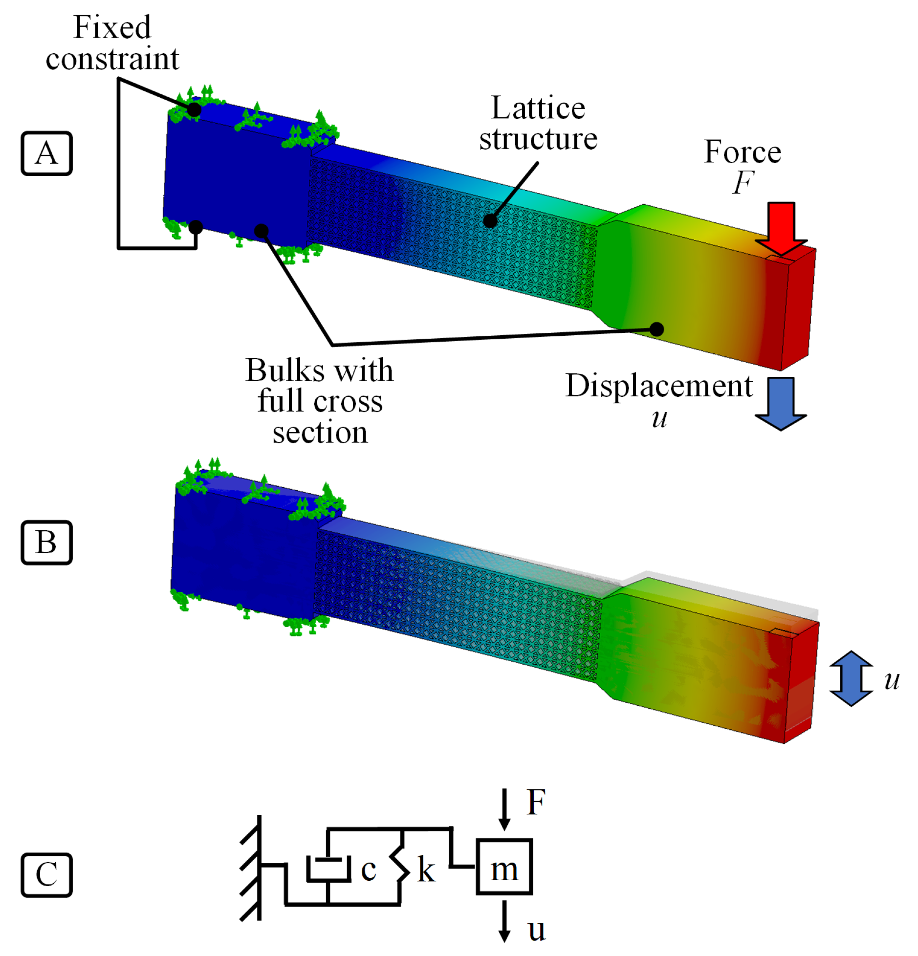
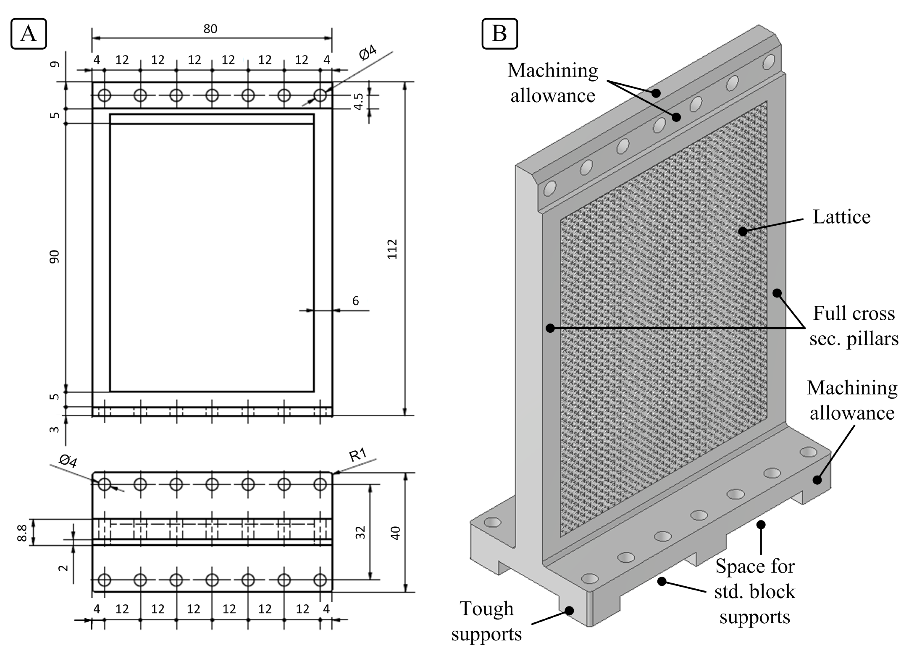
The blade-like thin-walled parts consisted of a lower base that could be easily clamped on a special platform dynamometer, a central section filled as specimens A, B, and C of Figure 2 and an upper base allowing mechanical clamping of the expendable workpiece to be milled. The central part was shaped including two full cross-section pillars positioned on both sides, ensuring mechanical toughness required to withstand SLM thermal stresses.
Orthogonal projections and an isometric view of the selected geometry are shown in Figure 6A, B, respectively. To obtain a slender but mechanically tough blade-like support, the geometry was designed in order to accommodate a lattice infill made of 34 × 4 × 45 unit cells (corresponding to blade type B).
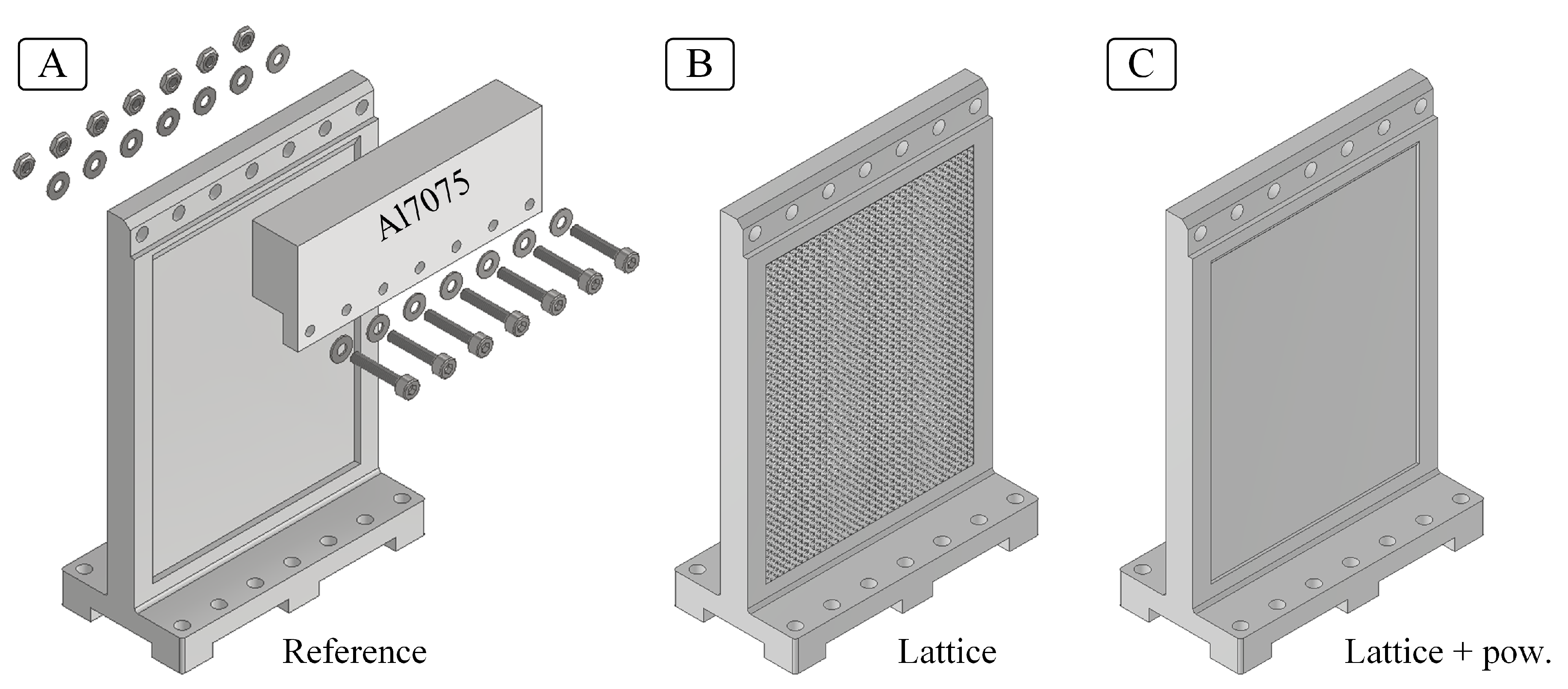
Applying the same procedure seen before, three blade-like supports variants were designed: the first with full density central region (denoted by A, acting as a reference), the second with an (open) lattice structure (B) and the third with a lattice structure closed by a metallic shell that retained the unmelted powder inside the structure (C). The design phase was carried out iteratively by using FE linear elastic analysis with Ansys Mechanical.
FE simulation was set by taking into account that lattice inclined beams diameter was bigger than expected due to the SLM manufacturing limitations. Therefore, inclined beams diameter was increased by 0.2 mm considering the systematic dimensional errors highlighted in [25].
Accurate numerical results in a reasonable computation time were obtained by using a mixed mesh composed of
  • tetrahedral and hexahedral solid elements (SOLID186) for the bulk parts;
  • circular cross-section Timoshenko beam elements (BEAM189) with a non-uniform beam diameter, as proposed by Guo et al. in [30], for the lattice structure. In detail, the diameter of beams near lattice joints was increased by 40% to simulate the effective joint stiffness of the lattice structure. The overall mass density had to be tuned to ensure compliance with true value. For a thorough analysis of the meshing strategy, see also [25].
The FE model of the blade-like support is shown in Figure 7. The geometry was simplified by eliminating the bottom base, holes, and chamfers. On the right side of Figure 7, the non-uniform Timoshenko beam mesh is shown in detail.
The rigid body motions of the lower base were constrained and the static compliance was evaluated in two significant positions: near to the lateral pillars (blade edge corner) and in the center position, applying one at a time the forces F 1 and F 2 on the upper base. Hence, the support with lattice and raw metal powder filler and the reference one were designed iteratively by FE in order to have similar static compliance and first resonance frequency with respect to the lattice one. To satisfy these constraints, the blade type C embedding both lattice and raw metal powder included 34 × 3 × 45 elementary cells and an outer shell of thickness equal to 0.3 mm. In addition, the central cross-section thickness of the reference blade-like part type A was set equal to 5 mm. CAD models of reference, lattice, and lattice with raw metal powders supports are shown in Figure 8A–C, respectively.
Milling tests were carried out on an Al7075 workpiece bolted to the upper base, as shown in Figure 8A. Optimal contact between workpiece and blade-like support was assured by finishing the contact surfaces.

3.2. Additive Manufacturing of Stainless Steel Blades with Internal Lattice Structures

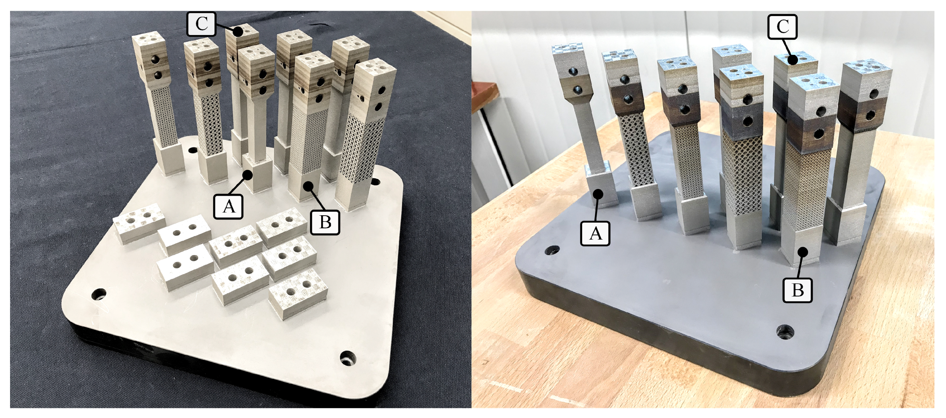
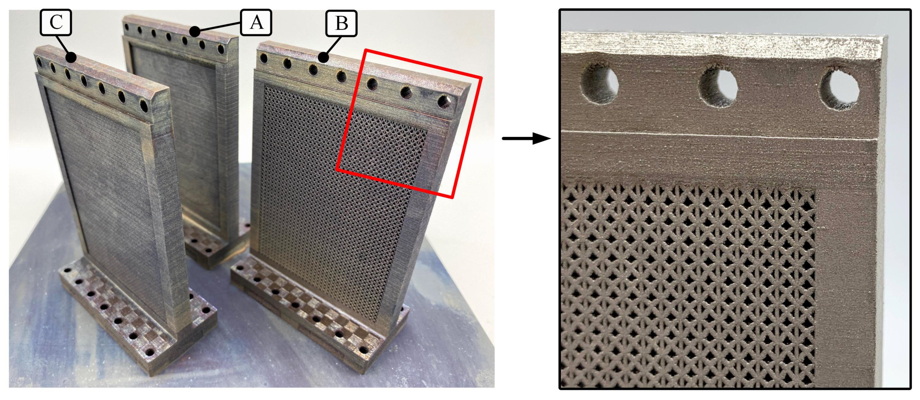
Additive manufacturing was carried out by positioning all three blade-like supports on the same build platform. A 45° orientation with respect to the coater blade was set in order to enhance re-coating phase powder spreading. The build process was designed by using the same equipment and process parameters adopted for the fabrication of the AISI 316L beam-like specimens.
Printing job was fulfilled in three and a half days. Hence, stress relieving heat treatment was applied (see Section 2.1) to reduce warping. Supports geometry was reproduced satisfactorily, without significant deformations or defects as shown in Figure 9. Lattice sections had no appreciable defects, cracking, or warping and dimensional accuracy was good as for beam-like specimens. As expected, the upper base holes were not circular due to the issues affecting overhanging surfaces derived from the SLM technique, but this was not a problem because an appropriate tolerance was foreseen during the design phase. The lower and upper parts of the blade-like support were re-machined in order to ensure an optimal contact with the dynamometer and with the workpiece.

3.3. Experimental Modal Analysis of Blades

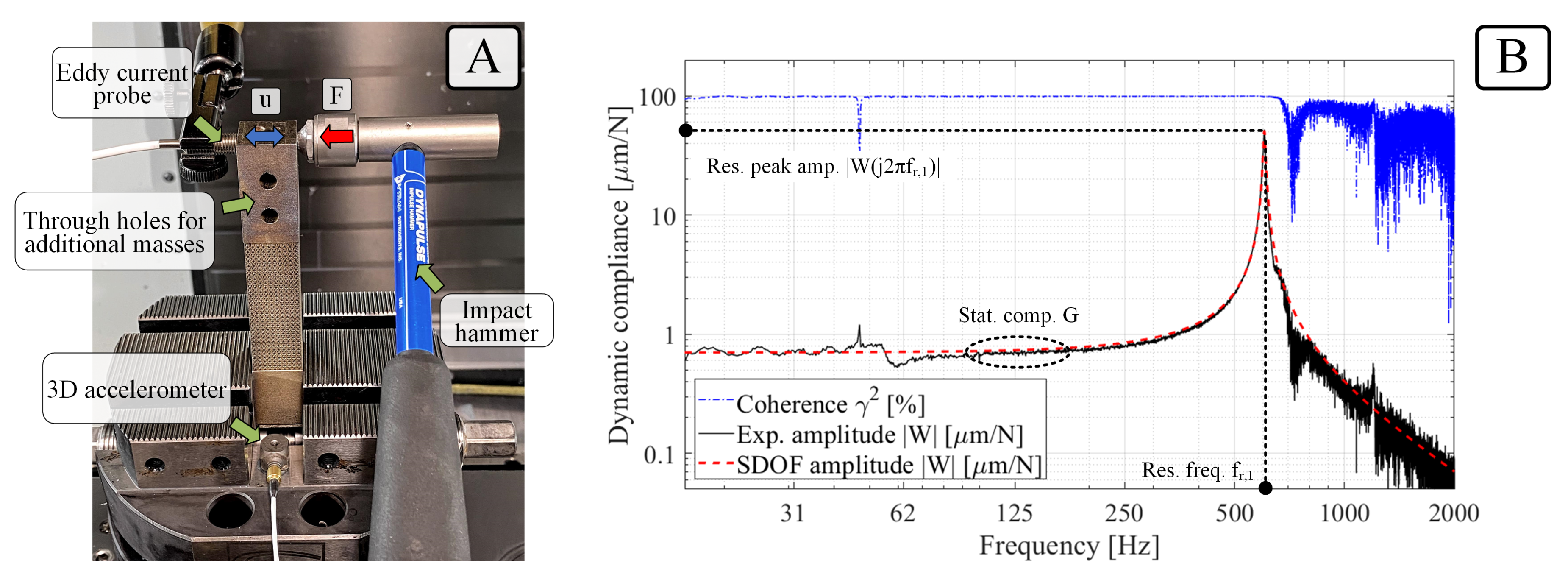
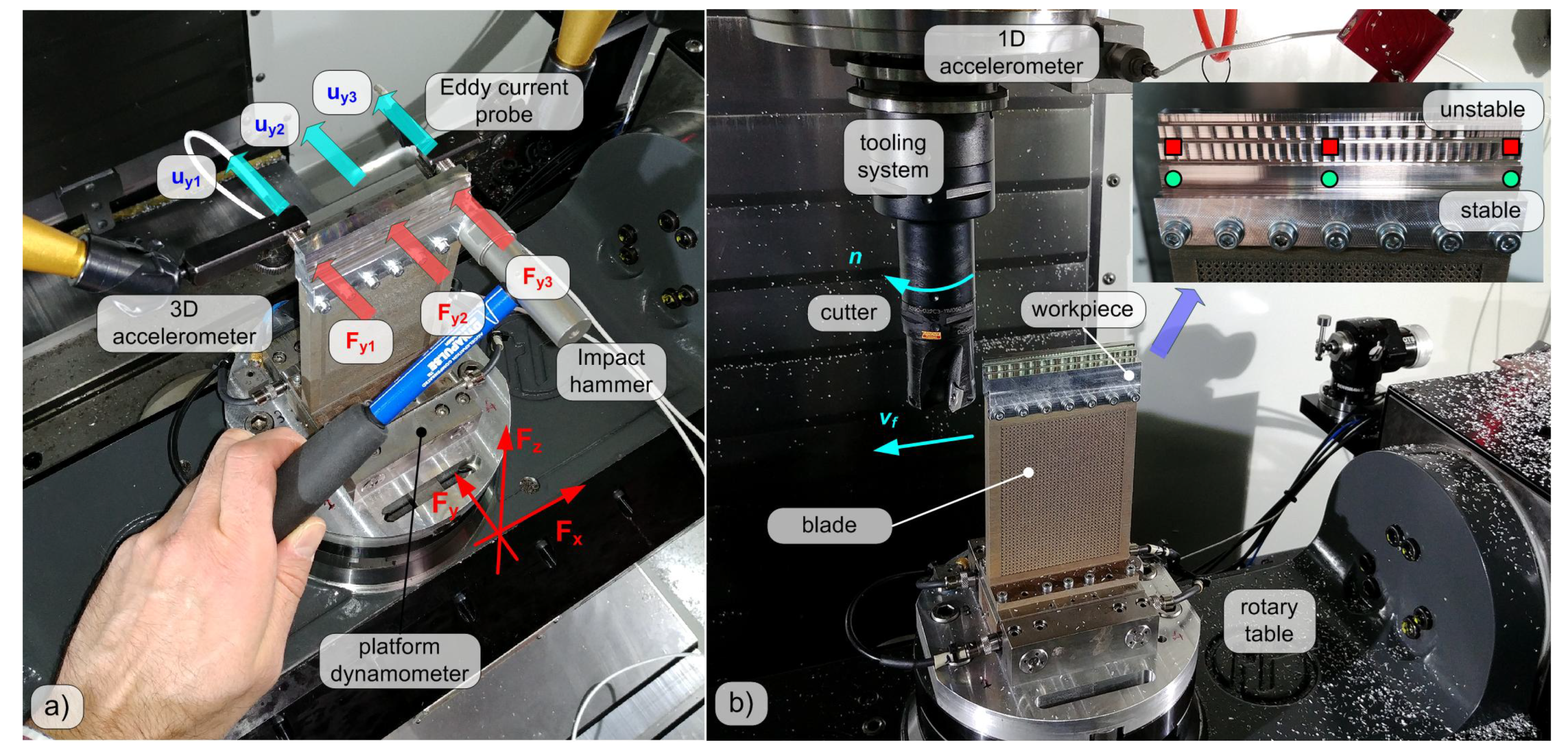
Experimental modal tests were carried out at the Laboratory for Advanced Mechatronics—LAMA FVG—Udine, Italy, on a five-axis CNC milling machine Haas VF-2TR, see Figure 10a. All sensor signals were sampled at 51.2 kHz by a National Instruments Data Acquisition device (cDAQ-9178 with NI9215 modules) and stored on a PC for further analysis, which was carried out in the MathWorks MATLAB environment.
First, each blade was clamped on a special platform dynamometer [31] embedding four triaxial high-sensitivity piezoelectric force cells Kistler 9016B4, similar to the Kistler Minidyn 9256C2 architecture. An Al7075 workpiece (approx. weight 78 g and hardness 150 HB, main shearing cutting pressure k c s 1000 MPa, normal shearing cutting pressure k n s 500 MPa) was fixed on the top of the blade by means of seven M3 fasteners.
Workpiece vibrations were also monitored by a triaxial accelerometer attached on the dynamometer base (Kistler 8764B50 having a sensitivity of about 100 mV/g).
Two eddy current displacement probes (Micro-Epsilon type ES1 with sensitivity—on the ERGAL workpiece—of about 30 mV/μm) were used for detecting blade tip transversal vibrations along the feed perpendicular Y direction.
Impulse forces were applied on the workpiece tip along the Y direction by using an instrumented impact hammer Dytran 5800B4 (sensitivity 2.41 mV/N). Three different locations were hit in order to stimulate both the bending and torsional vibrations modes of the blade, as illustrated in Figure 10a.
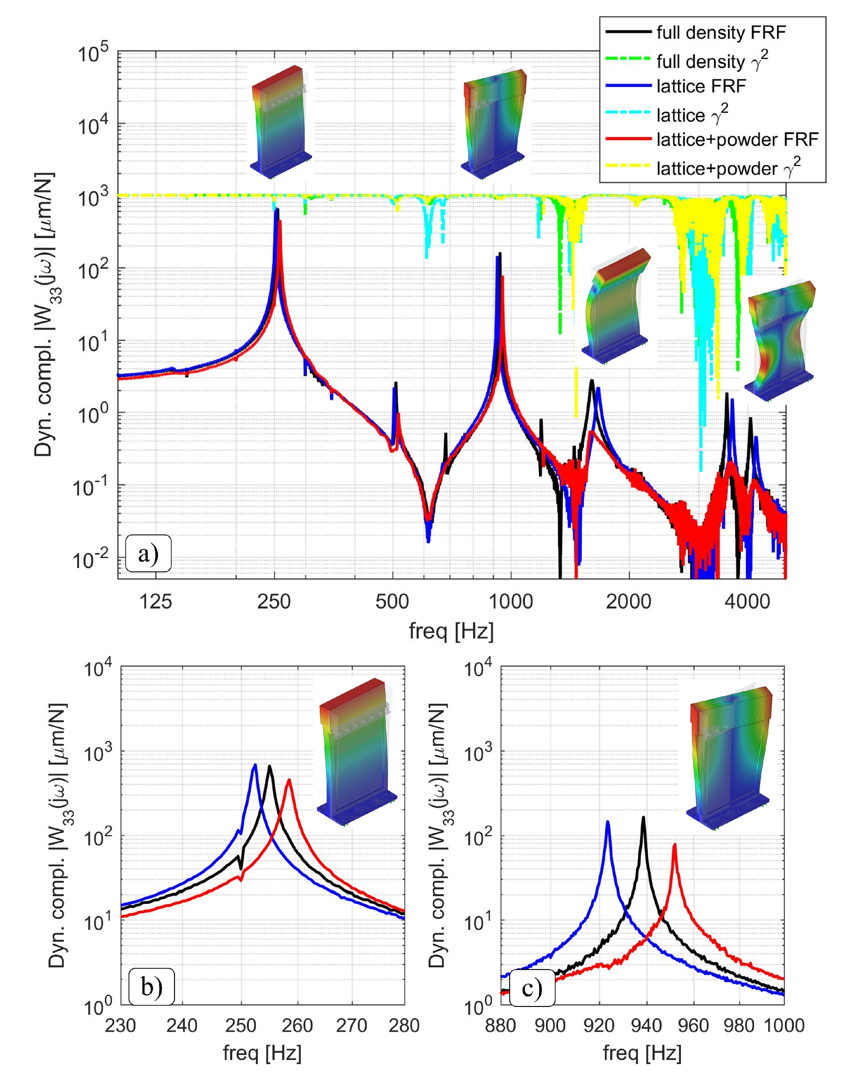
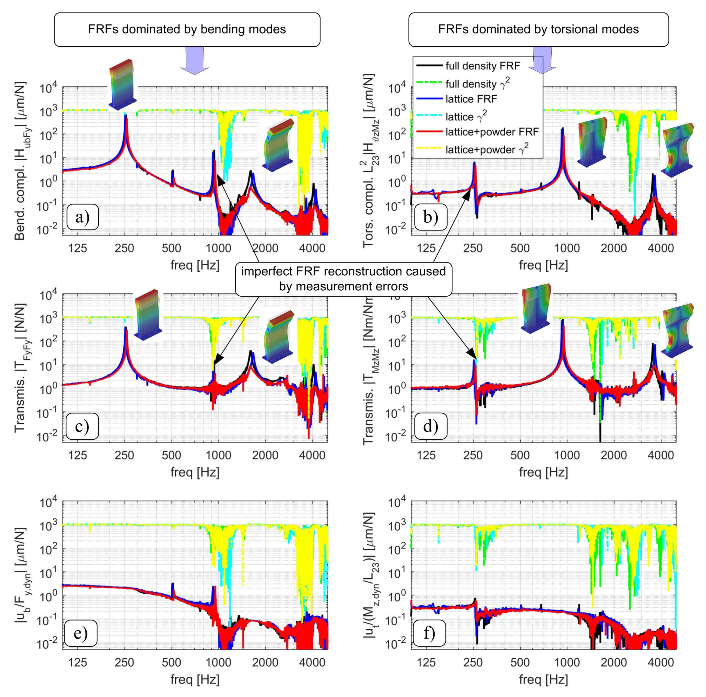
By doing so, the blade tip dynamic compliance W 33 j ω = u y 3 j ω / F y 3 j ω [μm/N] was determined, see Figure 11.
The experimental modal analysis procedure was repeated multiple times during the chatter tests, in order to take into account the variations of workpiece modal parameters due to the progressive material removal.
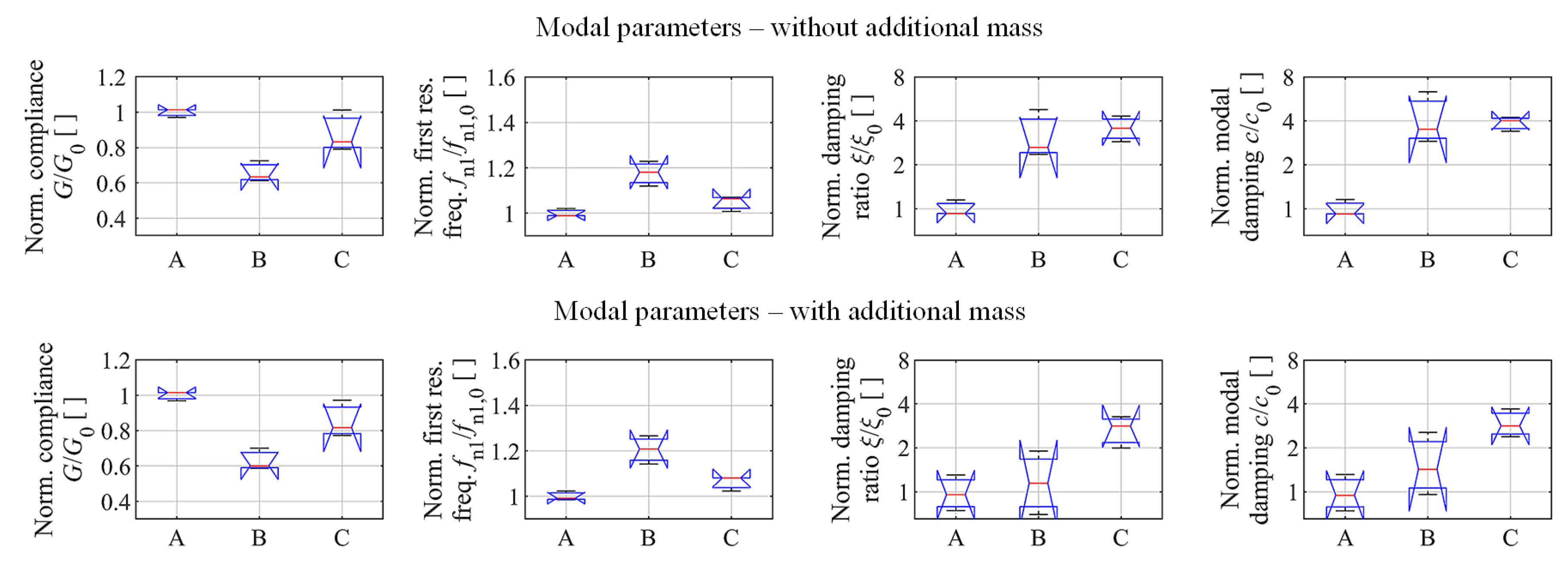
The results of modal analysis are reported in Figure 11 and Figure 12, and the obtained modal parameters are given in Table 2.
The blade embedding the lattice structure without powder presented damping properties similar to the full density case, thus suggesting that lattice structure alone is not capable of increasing damping of thin-walled mechanical components.
On the other side, the blade with lattice structure filled with powder exhibited a significantly higher damping. This result was also confirmed by the Rayleigh coefficients β i .
Bending modes were slightly influenced by the presence of powder. Torsional modes were much more attenuated by the presence of powder inside the lattice structure. However, the reasons of this behavior are still not clear and may deserve further investigations in the future.
The transverse vibrations at node 3 can be decomposed as follows:
u y 3 = u y 3 + u y 1 2 u b + u y 3 u y 1 2 u t
where u b u y 2 is the transverse vibration associated with the bending vibrations modes, while
u t = ϑ z L 23
is the term associated with the torsion ϑ z of blade tip around its vertical axis of symmetry. In this case, bending only depends on the F y force component, independently from force location, while torsion only depends on the torque M z , i.e., here they are dynamically decoupled. In other words,
u b j ω ϑ z j ω = H u b F y j ω 0 0 H ϑ z M z j ω F y j ω M z j ω
where H u b F y and H ϑ z M z are the dynamic compliances estimated from modal tests. When focusing on the blade corner at node 3, the torque will be given by M z = F y 3 L 23 . Thus,
u t j ω = L 23 ϑ z j ω = L 23 H ϑ z M z j ω M z j ω = L 23 2 H ϑ z M z j ω F y 3 j ω
In order to estimate both bending and torsional vibrations during the cutting process without a direct measurement through displacement probes, they were derived from dynamometer signals.
For this purpose, a quasi-static calibration procedure was first carried out in order to determine the linear combinations of load cell signals F y , d y n and M z , d y n approximating the effective F y and M z components. Their dynamic relation to the inputs is given by
F y , d y n j ω M z , d y n j ω T F y F y j ω 0 0 T M z M z j ω F y j ω M z j ω
where T F y F y and T M z M z are the direct transmissibilities that were also determined from modal analysis. Cross transmissibilites are negligible since the bending and torsional directions are decoupled.
Due to the inertial disturbances affecting dynamometer dynamics [32], the above transmissibilites are very sensitive to the bending and to the torsional vibration modes of the system, respectively. Accordingly, they can be exploited to detect them. By focusing on the first, dominant vibration modes, the bending vibrations u b are proportional to the measured F y , d y n component, i.e.,
u b j ω F y , d y n = u b j ω F y j ω H u b F y j ω F y j ω F y , d y n j ω T F y F y 1 j ω cost
and similarly the torsional vibrations u t are proportional to the measured torque M z , d y n , as follows:
u t j ω M z , d y n j ω M z , d y n j ω L 23 L 23 = L 23 2 ϑ z j ω M z j ω H ϑ z M z j ω M z j ω M z , d y n j ω T M z M z 1 j ω cost
This approximation is justified by observing the bottom of Figure 12. Thus, this practical result was exploited for estimating the blade edge vibrations close to the corner at node 3 that was also the entry point during each milling pass. Attention was focused on such blade corner because it was the most flexible point on blade top edge that was affected by both bending and torsional vibrations.

3.4. Chatter Tests

After modal analysis, some cutting tests were also executed by using a modular Sandvik Coromant tooling system composed of a spindle adapter (C5-390B.140-40 040), an intermediate adapter (C5-391.02-32 060A), and a face shoulder cutter (R390-032C3-11M050) with external diameter D = 32 mm. A single cutting insert ( Z = 1 ) Sandvik R390-11T304E-NL H13A with nose radius r ε = 0.4 mm, lead angle χ 1 = 90 ° and axial rake angle γ a 15 ° was mounted on the cutter in order to avoid the effects of run-out.
Spindle housing vibrations along the feed perpendicular direction Y were also measured during the cutting tests by a monoaxial accelerometer Kistler 8704B50 having a sensitivity of about 100 mV/g.
As explained din the previous subsection, the blade tip vibrations (at node 3) were derived from dynamometer signals.
Down milling tests with tool-workpiece lateral immersion a L / D = 0.63 % mm ( a L = 0.2 ) were performed according to a full factorial Design of Experiments, see Table 3.
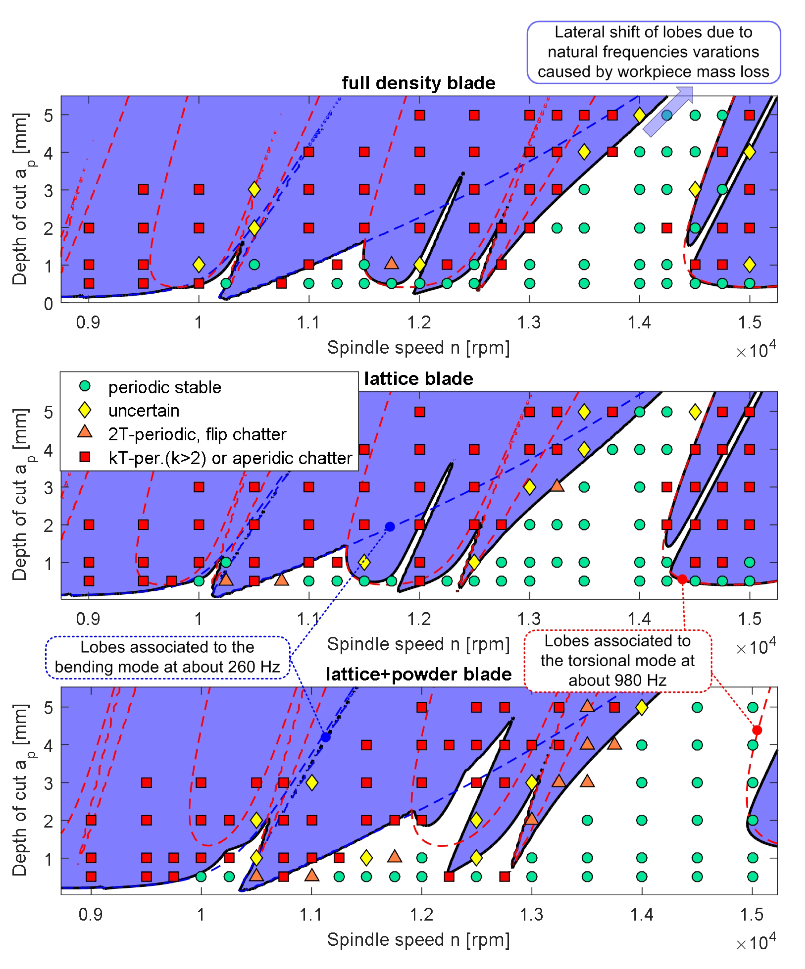
For each blade type and combination of cutting parameters, a complete milling pass was executed in order to assure stationary cutting conditions along blade edge. Another replicate of each test was executed in a different moment, with a different workpiece. After the execution of the two replicates, the cutting process was classified as shown in Figure 13. Specifically, it was classified as periodic stable when both replicates were stable, uncertain in the presence of one stable and one unstable result, flip in case of two flip (period doubling or 2 T -periodic) chatter outcomes, k T -periodic (with k 2 ), or aperiodic chatter otherwise.
Stability analysis was subsequently carried out by using the Improved Chebyshev Collocation Method [6,7]. The cutting tool was approximated as rigid, since its compliance was one order of magnitude smaller than that of the workpiece (in the feed perpendicular direction). The workpiece was assumed rigid along the feed direction as well.
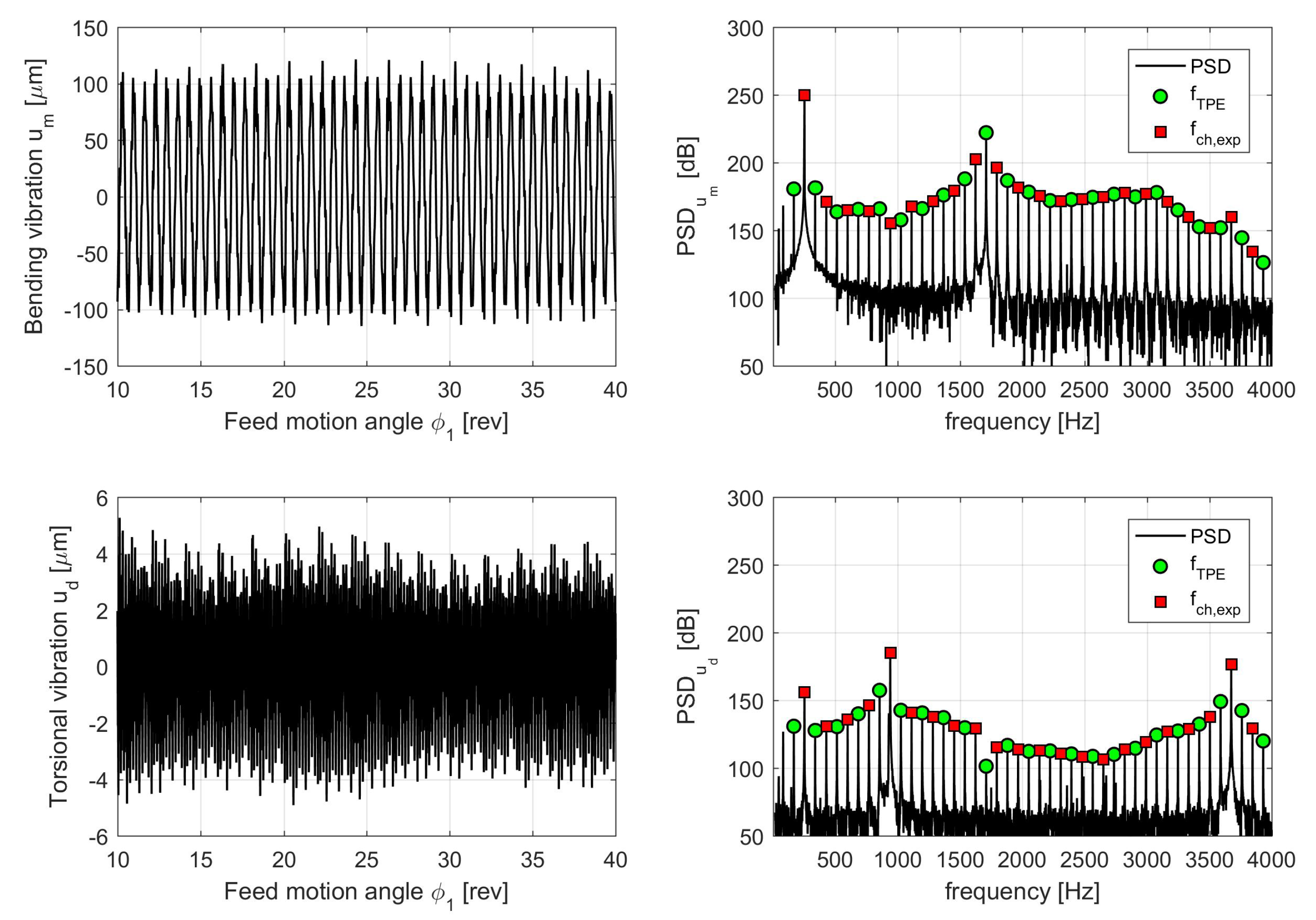
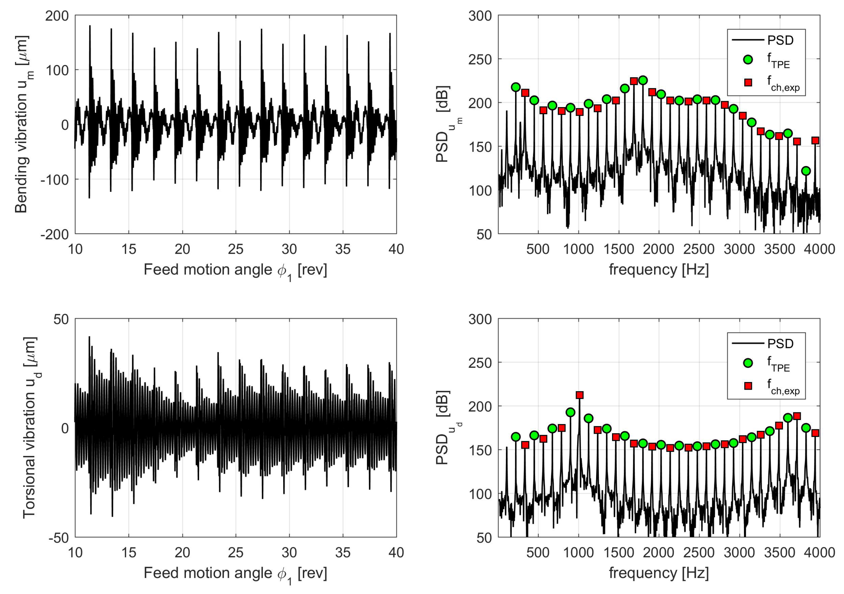
The predicted stability lobes were found in a very good agreement with the experimental points. As expected, they corresponded to the union of the stability lobes associated with the first bending mode and those associated with the first torsional mode, as illustrated in Figure 13. Due to the low immersion conditions, each mode gave rise to both Hopf and flip bifurcations, depending on the selected spindle speed level. Specifically, the occurrence of flip lobes associated with different vibrations modes was correctly predicted by the stability analysis, as is visible in Figure 14 and Figure 15 where bending vibrations u b or torsional vibrations u t were dominant.
Stability border obtained with full density blade and lattice blade are very similar because of their similar modal parameters. On the contrary, stability borders obtained with the blade embedding both lattice structure and powder were significantly different. In detail, the lobes associated with the first torsional mode were located at considerably higher depths of cut owing to the higher damping ratio. They were also shifted at higher spindle speeds because of the slightly different natural frequency of the first torsional mode. The combinations of both effects gave rise to wider stable regions, especially between 14,000 and 15,000 rpm.
Accordingly, only the lattice structure filled with unmelted powder is a promising solution for enhancing the damping properties and for passive chatter suppression of thin-walled structures.

4. Conclusions

In the light of the results found above, we may draw the following conclusions.
The analysis of literature evidenced that metallic lattice structures—made of AISI 316L and 3D printed by means of the Selective Laser Melting technique—may be a good candidate for attenuating mechanical vibrations of advanced parts.
Here, a novel idea was further tested, i.e., retaining the unmelted powder within the lattice structure by means of a 3D printed external shell. The powder grains should act as microscopic local dampers. The enhanced damping properties of such novel combination of lattice structure and filler type was investigated here for passive chatter suppression of thin-walled parts in milling.
A preliminary experimental study was first carried out on simple specimens, in order to assess the damping properties of the new lattice configuration filled with unmelted powder in comparison to the empty lattice and full density alternatives, for a given static compliance.
Measurements confirmed the higher damping properties of the proposed configuration, whereas the presence of lattice structures alone did not have a significant effect on damping with respect to the full density configuration, contrary to the results found in [25]. One possible reason is that here thin-walled lattice regions were investigated, while thicker lattice regions were considered in [25].
A blade-like benchmark representing a possible thin-walled workpiece or workpiece fixture was designed, in order to investigate the effects of the proposed internal structure (lattice filled with unmelted powder) for passive chatter suppression.
Each blade was clamped on a special platform dynamometer and an additional ERGAL workpiece was further clamped on the top of the blade. Experimental and numerical modal analysis was carried out on the assembled system. As a result, the most important bending and torsional vibration modes were identified at the blade corner that was recognized as the most flexible and critical point.
Modal analysis confirmed that only the lattice filled with unmelted powder configuration has enhanced damping properties. While damping increase regarding bending modes was moderate, the torsional modes were greatly attenuated in comparison to the other alternatives (full density and empty lattice).
A simple procedure was developed for estimating blade top edge vibrations during the cutting process from dynamometer signals alone, without the use of displacement probes. Bending and torsional vibrations were found to be proportional to the measured, raw (unfiltered) force F y , d y n and to the raw torque M z , d y n , thus their estimation was straightforward.
Eventually, chatter tests confirmed that the lattice with unmelted powder configuration may increase milling process stability in comparison to the full density and empty lattice configurations, thus allowing higher material removal rates.
From the perspective of an industrial application of the presented ideas, it is important to recall that the unmelted metallic powder is potentially inflammable, explosive, and toxic for humans. When machining the 3D printed part, the risk of powder ignition is negligible until it is retained inside the lattice structure by the external metallic shell, and cutting fluid is also used for cooling the cutting process. On the other side, the risk that the powder is released when the 3D printed part is under operative conditions cannot be in general neglected and it should be preliminarily evaluated case by case. For example, this wouldn’t be acceptable in biomedical applications.
However, the proposed internal configuration of 3D printed parts is promising and potentially advantageous for increasing the damping properties of the final mechanical component or for passive chatter suppression. It would be of further interest to investigate industrial applications that may benefit from the presented ideas.

Author Contributions

F.S.: Conceptualization, methodology, software, validation, investigation, data curation, writing—original draft preparation, visualization, and project administration. G.T.: conceptualization, methodology, software, validation, formal analysis, investigation, resources, data curation, writing—original draft preparation, visualization, and funding acquisition. E.V.: methodology, investigation, validation, writing—review and editing, supervision. M.S.: validation, resources, writing—review and editing, supervision, project administration and funding acquisition. All authors have read and agreed to the published version of the manuscript.

Funding

This research received no external funding.

Acknowledgments

The Laboratory for Advanced Mechatronics—LAMA FVG—of the University of Udine is gratefully acknowledged for technical support. LAMA FVG is an international research center for product and process innovation where the three Universities of Friuli Venezia Giulia Region (Italy) synergically cooperate for promoting R&D activities at the academic and industrial level.

Conflicts of Interest

The authors declare no conflict of interest.

References

  1. Yue, C.; Gao, H.; Liu, X.; Liang, S.; Wang, L. A review of chatter vibration research in milling. Chin. J. Aeronaut. 2019, 32, 215–242. [Google Scholar] [CrossRef]
  2. Zhu, L.; Liu, C. Recent progress of chatter prediction, detection and suppression in milling. Mech. Syst. Signal Process. 2020, 143, 106840. [Google Scholar] [CrossRef]
  3. Merdol, S.D.; Altintas, Y. Multi frequency solution of chatter stability for low immersion milling. J. Manuf. Sci. Eng. Trans. ASME 2004, 126, 459–466. [Google Scholar] [CrossRef]
  4. Insperger, T.; Stépán, G. Updated semi-discretization method for periodic delay-differential equations with discrete delay. Int. J. Numer. Methods Eng. 2004, 61, 117–141. [Google Scholar] [CrossRef]
  5. Ding, Y.; Zhu, L.; Zhang, X.; Ding, H. A full-discretization method for prediction of milling stability. Int. J. Mach. Tools Manuf. 2010, 50, 502–509. [Google Scholar] [CrossRef]
  6. Totis, G.; Albertelli, P.; Sortino, M.; Monno, M. Efficient evaluation of process stability in milling with Spindle Speed Variation by using the Chebyshev Collocation Method. J. Sound Vib. 2014, 333, 646–668. [Google Scholar] [CrossRef]
  7. Totis, G.; Insperger, T.; Sortino, M.; Stépán, G. Symmetry breaking in milling dynamics. Int. J. Mach. Tools Manuf. 2019, 139, 37–59. [Google Scholar] [CrossRef]
  8. Budak, E.; Tunc, L. Identification and modeling of process damping in turning and milling using a new approach. CIRP Ann. 2010, 59, 403–408. [Google Scholar] [CrossRef]
  9. Munoa, J.; Sanz-Calle, M.; Dombovari, Z.; Iglesias, A.; Pena-Barrio, J.; Stepan, G. Tuneable clamping table for chatter avoidance in thin-walled part milling. CIRP Ann. 2020, 69, 313–316. [Google Scholar] [CrossRef]
  10. Yang, Y.; Muñoa, J.; Altintas, Y. Optimization of multiple tuned mass dampers to suppress machine tool chatter. Int. J. Mach. Tools Manuf. 2010, 50, 834–842. [Google Scholar] [CrossRef]
  11. Burtscher, J.; Fleischer, J. Adaptive tuned mass damper with variable mass for chatter avoidance. CIRP Ann. 2017, 66, 397–400. [Google Scholar] [CrossRef]
  12. Munoa, J.; Iglesias, A.; Olarra, A.; Dombovari, Z.; Zatarain, M.; Stepan, G. Design of self-tuneable mass damper for modular fixturing systems. CIRP Ann. 2016, 65, 389–392. [Google Scholar] [CrossRef]
  13. Zhang, Z.; Li, H.; Liu, X.; Zhang, W.; Meng, G. Chatter mitigation for the milling of thin-walled workpiece. Int. J. Mech. Sci. 2018, 138–139, 262–271. [Google Scholar] [CrossRef]
  14. Wan, S.; Li, X.; Su, W.; Yuan, J.; Hong, J.; Jin, X. Active damping of milling chatter vibration via a novel spindle system with an integrated electromagnetic actuator. Precis. Eng. 2019, 57, 203–210. [Google Scholar] [CrossRef]
  15. Butt, M.; Yang, Y.; Pei, X.; Liu, Q. Five-axis milling vibration attenuation of freeform thin-walled part by eddy current damping. Precis. Eng. 2018, 51, 682–690. [Google Scholar] [CrossRef]
  16. Zatarain, M.; Muñoa, J.; Peigne, G.; Insperger, T. Analysis of the influence of mill helix angle on chatter stability. CIRP Ann. 2006, 55, 365–368. [Google Scholar] [CrossRef]
  17. Iglesias, A.; Dombovari, Z.; Gonzalez, G.; Munoa, J.; Stepan, G. Optimum selection of variable pitch for chatter suppression in face milling operations. Materials 2018, 12, 112. [Google Scholar] [CrossRef] [Green Version]
  18. Koca, R.; Budak, E. Optimization of serrated end mills for reduced cutting energy and higher stability. Procedia CIRP 2013, 8, 570–575. [Google Scholar] [CrossRef] [Green Version]
  19. Stepan, G.; Munoa, J.; Insperger, T.; Surico, M.; Bachrathy, D.; Dombovari, Z. Cylindrical milling tools: Comparative real case study for process stability. CIRP Ann. 2014, 63, 385–388. [Google Scholar] [CrossRef]
  20. Itoh, M.; Hayasaka, T.; Shamoto, E. High-efficiency smooth-surface high-chatter-stability machining of thin plates with novel face-milling cutter geometry. Precis. Eng. 2020, 64, 165–176. [Google Scholar] [CrossRef]
  21. Munoa, J.; Beudaert, X.; Dombovari, Z.; Altintas, Y.; Budak, E.; Brecher, C.; Stepan, G. Chatter suppression techniques in metal cutting. CIRP Ann. 2016, 65, 785–808. [Google Scholar] [CrossRef]
  22. Zeng, S.; Wan, X.; Li, W.; Yin, Z.; Xiong, Y. A novel approach to fixture design on suppressing machining vibration of flexible workpiece. Int. J. Mach. Tools Manuf. 2012, 58, 29–43. [Google Scholar] [CrossRef]
  23. Wan, M.; Gao, T.; Feng, J.; Zhang, W. On improving chatter stability of thin-wall milling by prestressing. J. Mater. Process. Technol. 2019, 264, 32–44. [Google Scholar] [CrossRef]
  24. Sortino, M.; Totis, G.; Scalzo, F.; Vaglio, E. Preliminary investigation of static and dynamic properties of SLM lattice structures for robotic applications. In Mechanisms and Machine Science; Springer: Cham, Switzerland, 2019; Volume 66, pp. 260–267. [Google Scholar] [CrossRef]
  25. Scalzo, F.; Totis, G.; Vaglio, E.; Sortino, M. Experimental study on the high-damping properties of metallic lattice structures obtained from SLM. engrXiv 2020. [Google Scholar] [CrossRef]
  26. Murray, G.; Gandhi, F.; Hayden, E. Polymer-filled honeycombs to achieve a structural material with appreciable damping. J. Intell. Mater. Syst. Struct. 2012, 23, 703–718. [Google Scholar] [CrossRef]
  27. Ramadani, R.; Belsak, A.; Kegl, M.; Predan, J.; Pehan, S. Topology Optimization Based Design Of Lightweight In addition, Low Vibration Gear Bodies. Int. J. Simul. Model. 2018, 17, 92–104. [Google Scholar] [CrossRef]
  28. Wang, R.; Shang, J.; Li, X.; Luo, Z.; Wu, W. Vibration and damping characteristics of 3D printed Kagome lattice with viscoelastic material filling. Sci. Rep. 2018, 8. [Google Scholar] [CrossRef]
  29. Mazur, M.; Leary, M.; McMillan, M.; Sun, S.; Shidid, D.; Brandt, M. Mechanical properties of Ti6Al4V and AlSi12Mg lattice structures manufactured by Selective Laser Melting (SLM). In Laser Additive Manufacturing: Materials, Design, Technologies, and Applications; Woodhead Publishing: Sawston, UK, 2016; pp. 119–161. [Google Scholar] [CrossRef]
  30. Guo, H.; Takezawa, A.; Honda, M.; Kawamura, C.; Kitamura, M. Finite element simulation of the compressive response of additively manufactured lattice structures with large diameters. Comput. Mater. Sci. 2020, 175, 109610. [Google Scholar] [CrossRef]
  31. Totis, G.; Dombovari, Z.; Sortino, M. Upgraded Kalman filtering of cutting forces in milling. Sensors 2020, 20, 5397. [Google Scholar] [CrossRef]
  32. Totis, G.; Adams, O.; Sortino, M.; Veselovac, D.; Klocke, F. Development of an innovative plate dynamometer for advanced milling and drilling applications. Measurement 2014, 49, 164–181. [Google Scholar] [CrossRef]
Figure 1. Specimen design and SDOF model: longitudinal section view of the beam-like specimen under linear static FEA (A) and under modal FEA (B); equivalent single harmonic oscillator model (C).
Jmmp 04 00117 g001
Figure 2. SLM-manufactured 316L specimens: first (left) and second (right) replicates.
Jmmp 04 00117 g002
Figure 3. Images of the three replicates of lattice structure type B acquired by a digital microscope, for quality and dimensional inspection.
Jmmp 04 00117 g003
Figure 4. Identification of the global dynamic behavior of the lattice structures: experimental setup for pulse testing.
Jmmp 04 00117 g004
Figure 5. Specimens’ modal parameters.
Jmmp 04 00117 g005
Figure 6. Blade-like benchmark geometry: dimensioned orthogonal view (A) and isometric view of the raw part after 3D printing (B).
Jmmp 04 00117 g006
Figure 7. Blade like support mesh, constraints, and loads.
Jmmp 04 00117 g007
Figure 8. Blade like supports CAD models.
Jmmp 04 00117 g008
Figure 9. SLM 3D printed supports: reference (A), lattice (B), and lattice + powder (C).
Jmmp 04 00117 g009
Figure 10. Experimental setup used for modal analysis (a) and chatter tests (b).
Jmmp 04 00117 g010
Figure 11. Blade dynamic compliance inspected at node 3. The lower resonance peaks of the blade embedding lattice structures and powder are visible in the enlarged views in the bottom of the figure.
Jmmp 04 00117 g011
Figure 12. Dynamic behavior of blade top edge derived from modal analysis: bending compliance (a) and torsional compliance (b). Dynamometer’s transmissibilities along the F y (c) and M z (d) directions. Dynamic relation between the bending vibration u b and the measured feed perpendicular force F y , d y n (e). Dynamic relation between the torsional vibration u t (evaluated at blade corner—node 3) and the measured torque M z , d y n acting on the workpiece with respect to the blade vertical axis of symmetry (f).
Jmmp 04 00117 g012
Figure 13. Comparison between experimental and predicted stability lobes, when adopting the full density blade (top) the blade with lattice structure (middle) and the blade embedding both lattice structure and unmelted powder (bottom).
Jmmp 04 00117 g013
Figure 14. Behavior in time and frequency domain of blade tip vibrations under flip chatter type, dominated by the first bending vibration mode. Blade type: lattice (without powder). Cutting parameters: n = 10,250 rpm, a p = 0.5 mm. Blade vibrations are derived from dynamometer signals. TPE = tooth pass excitation harmonics.
Jmmp 04 00117 g014
Figure 15. Behavior in time and frequency domain of blade tip vibrations under flip chatter type, dominated by the first torsional vibration mode. Blade type: lattice filled with powder. Cutting parameters: n = 13,500 rpm, a p = 4 mm. Blade vibrations are derived from dynamometer signals. TPE = tooth pass excitation harmonics.
Jmmp 04 00117 g015
Table 1. Summary of specimens’ geometrical features characteristics.
TypeFull Cross Sec. (A)Lattice (B)Latt. with pow. (C)
Central sec. typeFull cross sectionFBCCZFBCCZ
Cell size [mm]12 × 12 × 6022
Strut diameter [mm]-0.40.4
Cells along X & Y-108
Cells number along Z-3030
Cross section view Jmmp 04 00117 i001 Jmmp 04 00117 i002 Jmmp 04 00117 i003
Table 2. Modal parameters.
ParameterFull DensityLatticeLattice + Powder
Initial nat. freq. f n 1 [Hz]253.6251.9257.5
Final nat. freq. f n 1 [Hz]279.5278.8282.5
Initial nat. freq. f n 2 [Hz]935.6922.7953.0
Final nat. freq. f n 2 [Hz]983.0971.1996.8
Average damping ratio ξ 1 [ ]0.0025190.0023560.002968
Average damping ratio ξ 2 [ ]0.0007500.0007780.001368
Average static compl. G 1 [μm/N]2.3242.4381.966
Average static compl. G 2 [μm/N]0.2540.2630.146
Rayleigh damping coeff. β 1 = 2 ξ 1 / ω n 1 [μs]3.0082.8263.499
Rayleigh damping coeff. β 2 = 2 ξ 2 / ω n 2 [μs]0.2490.2620.447
Table 3. Design of experiments for the final chatter tests.
FactorLevelsValues
Blade type3full density, lattice, lattice+powder
Spindle speed n 13 ÷ 20 from 9000 to 15,000 rpm with steps of 250 or 500 rpm
Depth of cut a p 60.5, 1, 2, 3, 4, 5 mm
Replicates2-
Publisher’s Note: MDPI stays neutral with regard to jurisdictional claims in published maps and institutional affiliations.

