Article

A Rapid Throughput System for Shock and Impact Characterization: Design and Examples in Compaction, Spallation, and Impact Welding

Department of Materials Science and Engineering, The Ohio State University, Columbus, OH 43210, USA
*
Author to whom correspondence should be addressed.
J. Manuf. Mater. Process. 2020, 4(4), 116; https://doi.org/10.3390/jmmp4040116
Submission received: 15 November 2020 / Revised: 3 December 2020 / Accepted: 8 December 2020 / Published: 10 December 2020
(This article belongs to the Special Issue Impulse-Based Manufacturing Technologies)

Abstract

:
Many important physical phenomena are governed by intense mechanical shock and impulse. These can be used in material processing and manufacturing. Examples include the compaction or shearing of materials in ballistic, meteor, or other impacts, spallation in armor and impact to induce phase and residual stress changes. The traditional methods for measuring very high strain rate behavior usually include gas-guns that accelerate flyers up to km/s speeds over a distance of meters. The throughput of such experiments is usually limited to a few experiments per day and the equipment is usually large, requiring specialized laboratories. Here, a much more compact method based on the Vaporizing Foil Actuator (VFA) is used that can accelerate flyers to over 1 km/s over a few mm of travel is proposed for high throughput testing in a compact system. A system with this primary driver coupled with Photonic Doppler Velocimetry (PDV) is demonstrated to give insightful data in powder compaction allowing measurements of shock speed, spall testing giving fast and reasonable estimates of spall strength, and impact welding providing interface microstructure as a function of impact angle and speed. The essential features of the system are outlined, and it is noted that this approach can be extended to other dynamic tests as well.

1. Introduction

Equation of state (EOS) describes the states and thermodynamic properties of the material, and its measurement is of immediate interest in military, automobile, aerospace, and other several manufacturing applications [1]. Numerous approaches have been developed for obtaining the EOS of a variety of materials through dynamic shock wave compression [2], static compression [3] and static coupled with dynamic compression techniques [4]. To investigate material behavior under dynamic loading, dedicated facilities such as gas guns, rail guns, shock guns, electrothermal gun accelerators, laser driven flyer impacts and even explosives have been used effectively [5,6,7,8,9,10]. The present work attempts to formalize and standardize new techniques that can make dynamic studies more accessible and improve throughput dramatically. Vivek et al. [11] have developed the Vaporizing Foil Actuator (VFA) technique for many impulse and impact processes, such as impact welding [12,13], forming and embossing [14], shearing [15], and high-energy rate metalworking [16]. In this method, the pressure created from the electrically driven rapid vaporization of a thin aluminum (Al) foil is used to generate an immense transient pressure that can be used to launch projectiles to velocities well in excess of 1 km/s. Flyer speeds can be accurately measured with a laser-based technique, Photonic Doppler Velocimetry (PDV), the working principles for which can be found elsewhere [17]. In the present work, three critical dynamic material phenomena are shown as examples of the utility of this system: powder compaction, spallation, and impact welding.
Dynamic powder compaction (DPC) can reach higher densities than static compaction [18] and offers near-net-shape part fabrication by which subsequent finishing operations are minimized or eradicated, resulting in cost-effective manufacturing [19]. All consolidation processes including conventional hydraulic pressing, forging, hot/cold isostatic pressing, triaxial compaction [20] retain residual porosity, which during the sintering process leads to dimensional changes. Several DPC techniques using explosive compaction, gun-type units, hydraulic impact, spring-loaded hammers, and electromagnetic impulse units have been reported to improve the green density of compacts [21]. Green compacts with low defects and uniform density are essential for the fabrication of a high strength with little and uniform shrinkage. For DPC, higher densification is ascribed to the passage of the shock wave through the powder when the impact source hits the powder mass. Sethi et al. [22] demonstrated that DPC yields better green strength of the compact compared to the conventional compaction technique. Wang et al. [23] carried out DPC by high-energy impact delivered by a hammer with a mass of 135 kg traveling at speeds of 7–10 m/s. The result showed that the green density and bending strength of compacts increase with an increase in impact velocity due to an increase in shock wave pressure. Sometimes, multiple impacts have also been used to increase green density [24,25] In the past, particular interest has been given to DPC of metallic powders using explosives [26,27]. Though very high densities have been achieved, there have been issues with reflected shock waves producing cracking after initial consolidation [26,27].
Spallation is one of the significant modes of material failure during high-velocity impact. During impact, the interaction of the incident and reflected shock waves inside the material causes an internal fracture and separation of the outer surface. Knowledge of the spall strength of the material is essential in designing armor, military vehicles, and aircraft structures [28,29,30]. In this regard, Forbes [31] indicated that the Hugoniot Elastic Limit (HEL) is dependent on the thickness of the specimen and ultimately affects the spall strength of the component. Apart from these, it was concluded that the spall strength depended on several factors, including the processing route of material, anisotropy of the material and directional distribution of the second phases. In recent years, significant advances have been made to generate high tensile stress at high strain rates, which led to the generation of the database for known strategic materials [32,33,34]. Copper has been used as a common model material to study incipient spall strength and its correlation to microstructure and crystal orientation [35,36]. Hence, considering the vast amount of data available, the polycrystalline copper material (Cu110) was chosen for the present work.
Impact welding is a high strain rate, solid-state joining process. It is complex and involves high pressure and high local strains. These cause removal of the initial surfaces by jetting and the high pressure produces intimate contact. High transient temperatures can also cause melting and the formation of brittle intermetallic compounds. Furthermore, the process can cause wave formation dominated by fluid dynamics. Several groups have studied these phenomena and supporting microstructural representation can be found in the literature by Lee et al. [37]. Kuzmin and Lysak [38] experimentally proved that successful collision welds depend not only on the impact velocity but also on the collision angle. Zhang et al. [39] reported that successful collision welds are generally obtained when the collision velocity is between 150 and 1500 m/s and the collision angle is between 5° and 20°. With optimal welding parameters, melting can be favorably suppressed and localized or eliminated, creating minimal to no intermetallic formation. Metals that are difficult or impossible to join using conventional welding methods are therefore able to be joined using collision welding technique. In this regard, different welding technologies viz. explosive welding [40,41], magnetic pulse welding [42], underwater explosion [43] and laser impact welding [44] have been extensively used in the past, and the limitations of these techniques are mentioned by Ngaile et al. [45]. Recently, vaporizing foil actuator welding (VFAW) techniques have been extensively used to weld the target with varying oblique angles for a different class of materials including AA1100-O to AISI1018 [46], 15-5 PH SS [47], Cu110 to CP-Ti [48,49], OFHC copper to Grade 2 Ti [50] and many more combinations of exotic materials. A versatile tool based on the vaporizing foil actuator is described here, and the first results from the aforementioned three experiments are presented.

2. Materials and Methods

In the present work, the VFA technique assisted projectile acceleration and the impact drove impulse-based dynamic characterization experiments in powder compaction, spallation, and collision welding of inclined target samples. A similar approach using electric gun technology at Lawrence Livermore Laboratory discusses problems of interest to shock-wave researchers [51,52]. For this purpose, a chamber for dynamic processing and characterization was designed and fabricated at the Impulse Manufacturing Laboratory at The Ohio State University (http://iml.osu.edu). A schematic CAD model and fabricated chamber with details are depicted in Figure 1. The chamber is equipped with an automated pneumatic control pedestal system to transmit and control energy. The base structure of the operational level inside of the chamber is electrically insulated using Garolite G-10 material (glass-fiber-reinforced epoxy) material. The chamber has ports to allow entry to focusing probes from a time-domain multiplexed 16-channel PDV system. This PDV system is built with standard arrays of 4 × 4 probes that allow measurement of workpiece velocity, position, and acceleration and its essential construction is described in greater depth elsewhere [17]. The 16-channel PDV system allows for a more accurate and higher resolution measurement of deformation fields generated by VFA launch or impact.
The measurement of impactor speed is carried out separately from material characterization experiments. Figure 2a depicts the schematic of the dynamic experimental setup with the PDV probe for the measurement of impact velocity. A tool steel (S7 steel) barrel with a total length of 30 mm and an inner bore diameter of 12.8 mm was used to house the projectile. Aluminum (Al 6061-T6) projectiles with 12.5 mm diameter with different lengths of 10 mm and 5 mm were used to understand its effect on the impact velocity. Additionally, a composite projectile consisting of a 1-mm-thick steel impactor (AISI 1018) backed by a 4-mm-thick aluminum puck (Al 6061-T6) was used in order to increase the impact pressure. An industrial adhesive (J-weld) was used to join the impactor and puck. Furthermore, graphite-based lubricant or motor oil was used to reduce friction from the bore wall and increase projectile speed. A thin piece of polyvinyl chloride (PVC) and an aluminum sheet (6061-T6) of 1 mm was placed at the bottom of the barrel to increase the stability and efficiency of the plasma-driven acceleration of the projectile, separating the projectile from two-layered aluminum foils. Two layers of aluminum foils (Al1100) with a thickness of 0.0762 mm were connected to the copper terminals. The copper terminals are connected to the terminals of the capacitor bank.
For all experiments, a current with an amplitude around 200 kA was rapidly discharged from the capacitor bank through the terminals to the aluminum foils, causing nearly instant vaporization of the foil, as has been detailed elsewhere [11,53]. The generated impulse plasma pressured and sheared the PVC and aluminum sheets through the barrel, accelerating the projectile to a high velocity traveling along the barrel. The input energy was set to be 14 kJ. The capacitor bank is a 16-kJ commercial Magneform system with a total capacitance of 462 μF, short circuit current rise time of 12 μs, an inductance of 100 nH, and resistance of 10 mΩ. All the conductive parts of the fixture were insulated with KaptonTM tape to avoid alternate current paths other than through the foil. A piece of transparent polycarbonate was placed at the top of the barrel, and a steel backing block with a hole pattern was positioned on top of the polycarbonate to secure and protect the PDV probe. A 25 mm focuser probe was used to measure the projectile velocity and a collimator was used to measure the velocity of free surfaces.
After determining projectile velocity, the same experimental setup was used for powder compaction, spallation, and collision welding of inclined target samples as shown in Figure 2b–d, respectively. For carrying out powder compaction experiments, commercially pure titanium (CP-Ti) powder was filled inside the upper barrel as depicted in Figure 2b. Detailed material description of the used CP-Ti powder can be found elsewhere [15]. Thin steel foil (SS304) just above the lower barrel was used to hold the powder, and the steel foil (SS304) at the top was used to measure the free surface velocity of the compacted powder. For spallation experiments, a 4 mm thick copper target (Cu110) was kept at the top of the lower barrel and backed by an upper barrel as presented in Figure 2c. Polycarbonate was kept at the top of the barrel to capture the spalled fragments. In order to study impact welding, a specific angle of 20° was machined into a 4mm thick copper target plate as shown in Figure 2d. This inclined target provides the collision angle required for impact welding. Finally, the PDV data collected was exported to MATLAB to analyze the speed resulting from initial projectile velocity and subsequent experiments. The voltage and current traces from the corresponding experiments were also collected using a 1000:1 BK PR28A voltage divider and a 50 kA: 1 V Rogowski coil, respectively.

3. Result and Discussion

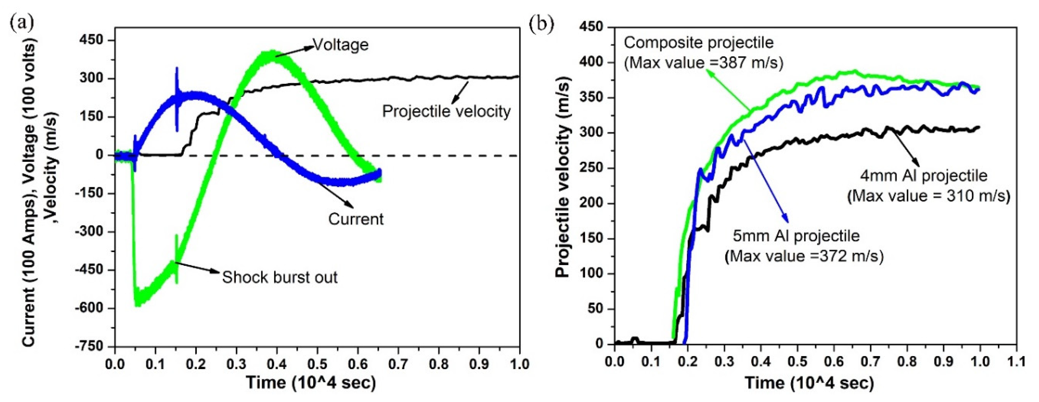
3.1. Effect of Projectile Configuration on Impact Velocity

As discussed earlier, VFA experiments using different projectile lengths and masses were used to understand their effect on impact velocity. The output of time-based evolution of current, voltage, and velocity using an aluminum projectile with 10 mm length at 14 kJ energy input is shown in Figure 3a. The voltage profile showed a sudden pop-in trace around 15 µs, and the instance is usually referred to as the shock burst out time. This kink in voltage is due to foil vaporization into high-pressure plasma [15]. Subsequently, an increase in voltage and a decrease in current was observed. At the same instance, the projectile started to gain its momentum, and the projectile approached a stagnation velocity of 310 m/s at about 40 µs. The velocity trace of different projectile configuration with 14 kJ input energy is shown in Figure 3b. It can be observed that the impact velocities were 310 m/s, 387 m/s and 372 m/s for an aluminum projectile with a 10 mm length, 5 mm length, and a composite projectile, respectively. Similarly, it is evident from the figure that the higher mass in the composite projectile led to a lower velocity compared to the 5 mm aluminum projectile. Repeatability was confirmed by testing two specimens at each condition.

3.2. Effect of Lubrication on Projectile Velocity

Graphite-based lubricant or motor oil was applied between projectile and barrel surfaces to reduce the sliding friction. Prior to each experiment, the barrel was cleaned with extreme care using acetone to avoid any external resistance from the scale produced from the previous experiment. It was observed that the usage of different lubrication had no mitigating difference in impact velocity. However, motor oil was used for further analysis due to consistency in results. Figure 4 presents the comparison of projectile velocity for both unlubricated and lubricated cases. The maximum impact velocity using lubricated 5 mm aluminum and the composite projectile showed an approximate increase by 2.5 and 1.7 times with respect to the unlubricated condition. Lubricated conditions had a significant effect on impact velocity compared to experiments without lubrication. Repeatability was ensured by carrying out two experiments at each conditions. Henceforth, projectiles with motor oil lubrication were considered for the different case studies discussed in the subsequent sections.

3.3. Case Studies

3.3.1. Powder Compaction of CP-Ti

An example of using this system for powder compaction and its relevant diagnostics follow. The CP-Ti powder was loaded into the 30 mm barrel and found to be compressed to 11.4 mm and 8.7 mm lengths when the 5 mm aluminum and the composite projectiles was used, respectively. The corresponding compacts are shown in Figure 5a. The setup data and results of the two experiments are consolidated in Table 1. Subsequently, the densities of both of the compacts were determined using the Archimedes principle. It can be seen that the compact obtained using the composite projectile showed a higher relative density of 88% compared to the 74% dense compact using the 5 mm aluminum projectile. The higher densification is postulated to be because a higher pressure is imparted into the powder body by the composite projectile which as a steel tip, which has a higher shock impedance [54]. A similar result was found for compacting CP-Ti powder using a VFA assisted sheared flyer [15].
DPC involves propagation of a compressive shock wave through a powder to cause its densification as mentioned by Vogler and coworkers [18,55,56]. The work details planar shock experiments on porous powders consolidation on a stepped die provided by a gun-driven impactor. The experiment is further identified with shock arrival time measurements on the sample impact and rear surfaces using velocity interferometry (VISAR) probes to obtain an accurate measurement of shock velocity and, consequently, determine the EOS or shock Hugoniot state. A similar approach using PDV was adopted to estimate flyer velocity, free surface velocity, and shock velocity through composite projectile impact as depicted in Figure 5b. The maximum flyer velocity and free surface velocity were found to be around 885 m/s and 190 m/s, respectively. The reduction in velocity is due to the energy expended for powder compaction. The movement of the flyer starts at a time of 1.06 × 10⁻⁴ s, whereas the free surface motion was encountered around 1.6 × 10⁻⁴ s. From this, the average shock speed was estimated to be approximately 555 m/s. By measuring the shock velocity, the impact pressure can be determined for a material for which EOS is known [57,58]. Moreover, by repeating this procedure for different impact velocities and measuring shock pressures using gauges such as manganin [59] and attenuator material [60], empirical for EOS can be determined for unknown material.

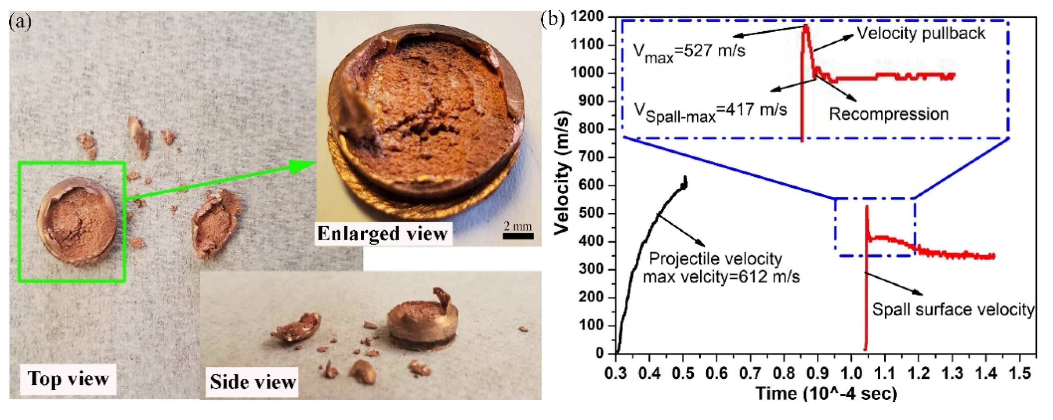
3.3.2. Spallation in Copper

In the present work, the copper sample resulting in spall with a large spalled top surface with one piece along with several smaller shards was collected as presented in Figure 6a. Figure 6b shows the PDV velocity traces of the composite projectile and free surface near the shock wave breakout. The impactor speed before colliding with the target was is estimated at 612 m/s. The resulting initial breakout speed of the spalled sample was found to be approximately 527 m/s. The spall speed being lower than impactor speed is expected given the lower density of the steel impactor compared to the copper target. The voltage traces obtained from the experiments confirm the initiation of impactor movement and spall. The velocity profile shows the clear spall signatures that consist of a release into tension represented by velocity pullback; furthermore, the occurrence of spall at the velocity minimum as presented in Figure 6b. In the same instance, recompression waves propagate in both directions from near the spall plane denoted by a small spike in the velocity profile. Subsequently, recompression appears as a velocity increase after spall, and it is followed by ringing in the spall scab. The deceleration in the curve observed after the first shock denotes continuing damage evolution until the spall scab completely separates from the bulk copper plate.
The data collected from the spall experiment was used to estimate the spall strength as per the commonly used procedure [33,61] and Equation (1).
σ spall = ρ C ( V max V Spall max ) 2
where ρ denoted the density of copper (8950 kg/m3) and C is bulk sound speed in copper material (4600 m/s). The strain rates were calculated by applying a classical acoustic approximation as given by Equation (2) [62].
ε ˙ = 0.5 ( V max V Spall max ) C Δ t
where Δt is the time difference between Vmax and VSpall-max, and was obtained from the velocity spectrogram plot as shown in Figure 6b. The average spall strength for the 4 mm thick copper sample was estimated to be approximately 2.26 GPa and the average strain rate was around −2 × 10⁴ s−1. The obtained spall strength and the average strain rate was in the range mentioned by Turley and coworkers [33,61]. Extensive studies by Remington et al. [62] concluded that decreasing sample thickness results in higher strain rates by almost 10 times and an increase in spall strength by 30% as compared to that of its counterparts. Furthermore, materials shocked by a high power laser show a rapid increase in the spall strength with the strain rate at about 107 s−1 [63]. Thus, a dependence of spall strength on strain rate and sample thickness for an unknown material can be established using this tool.

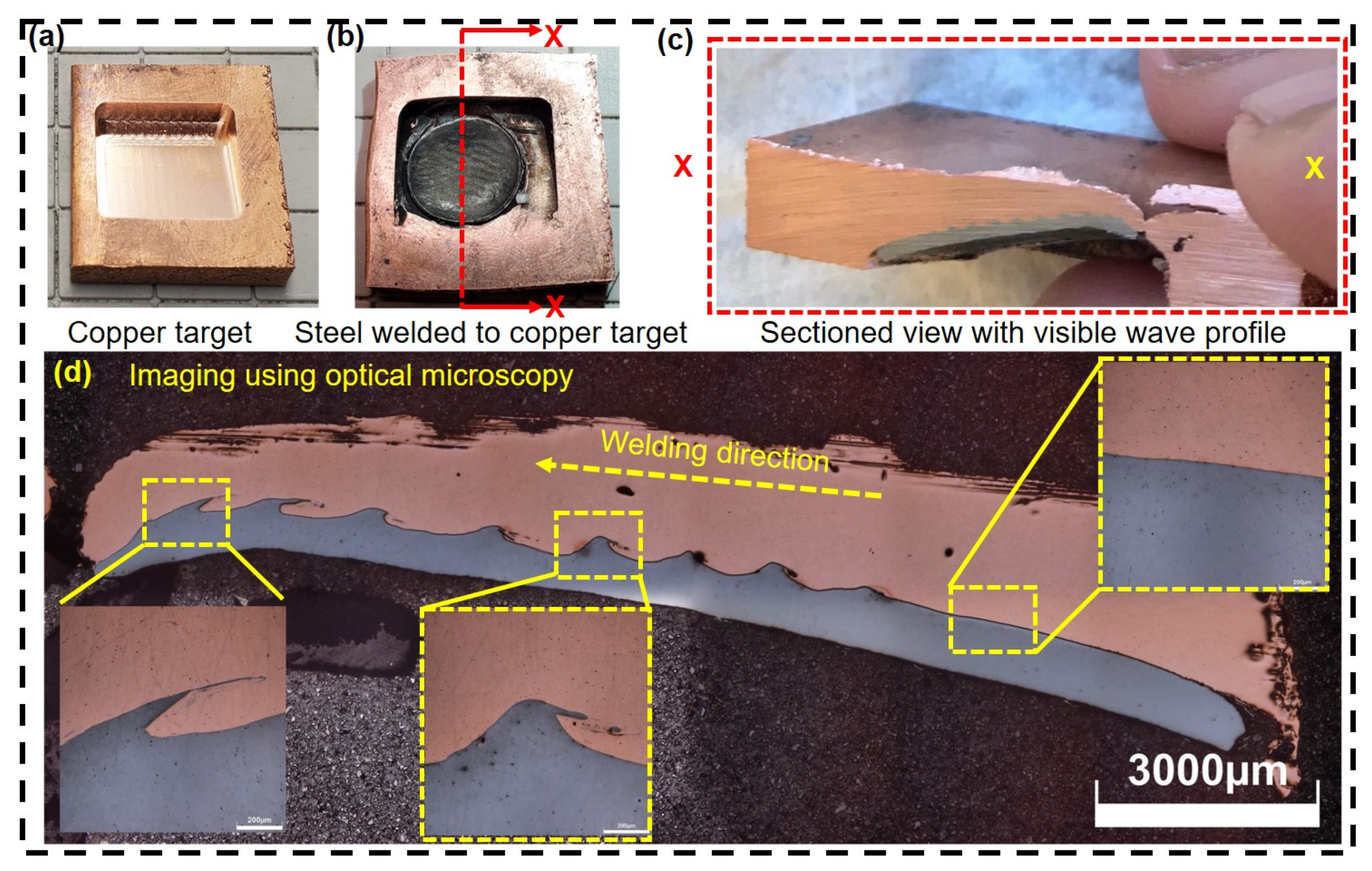
3.3.3. Collision Welding of Inclined Target

For collision welding, the lubricated composite projectile was launched at 14 kJ input energy level with an impact speed of 612 m/s (refer Section 3.2) to the copper target. The kinetic energy of steel tip of composite projectile was estimated to be 186.7 J. The copper target grooved with 20° inclination angle is shown in Figure 7a. The steel part became detached from the composite projectile and welded to the copper target as shown in Figure 7b. The detachment of steel from the aluminum might have occurred due to the generated reversal wave that had higher strength than the bonding strength of the material. Furthermore, the material was sectioned along an X–X contour for optical microscopy as shown in Figure 7c. A clear wave profile signifying a strong impact weld is visible even with unaided eyes. A work by Ngaile et al. [45] where a copper flyer mass of 14.82 gm was launched towards steel target using a chemically produced hydrogen energy-based impact technique. A similar wavy weld profile at the steel–copper interface was observed with an impact speed and kinetic energy of 637 m/s and 3000 J, respectively.
Figure 7d shows that an ungapped intimate contact weld interface was obtained over the entire length imaged using optical microscopy. The large consistent waves going along most of the welded interface are a testament to a constant impact angle during the welding process, which has not been previously obtained with VFAW [64]. The waviness of the interface starts a few mm after the start of welding. The weld’s bonding strength can be estimated using the micro-tensile test [65]. A similar phenomenon of delay in wave initiation was observed during explosive welding [66]. Szecket et al. demonstrated that the strong waves are commonly allied with the best-welded joints, although they are not a prerequisite [67].

4. Summary

This work’s objective was to present the new and rapid throughput experimental setup to do shock physics and impulse manufacturing experiments. Three applications, namely powder compaction, spallation, and impact welding experiments, were presented using the proposed facility. The first one deals with dynamic compaction of titanium powder and conventional measurement of free surface velocity to evaluate shock velocity through the compact loaded barrel. In the second part, the spall strength and strain rate of polycrystalline copper were estimated. The third application relates to metallurgical bonding between the steel and copper plate with a 20° inclined groove. The experimental results substantiate the potential of a powerful new tool to study dynamic material behavior and related processes.

Author Contributions

Conceptualization, K.S.P., Y.M., A.V.; methodology, K.S.P., Y.M., A.V.; software, Y.M.; formal analysis, K.S.P., Y.M.; investigation, K.S.P., Y.M.; resources, A.V., G.S.D.; data curation, K.S.P., Y.M., A.V.; writing—original draft preparation, K.S.P.; writing—review and editing, K.S.P., Y.M., A.V., S.R.N., G.S.D.; visualization, A.V., S.R.N., G.S.D.; supervision, A.V., G.S.D.; project administration, G.S.D. All authors have read and agreed to the published version of the manuscript.

Funding

This research received no external funding.

Acknowledgments

The authors are thankful to National Science Foundation (NSF) under a Major Research Instrument grant number: 1531785 for the funding received for carrying out this research work. The authors acknowledge Impulse Manufacturing Laboratory (IML) members for their valuable help in carrying out these experiments.

Conflicts of Interest

The authors declare no conflict of interest.

References

  1. Davison, L.; Graham, R.A. Shock compression of solids. Phys. Rep. 1979, 55, 255–379. [Google Scholar] [CrossRef]
  2. Wang, H.; Zhang, W.; Wan, Y.; Chu, G.; Chen, D. Study on equation of state and spall strength of sintered Nd-Fe-B magnets. J. Magn. Magn. Mater. 2020, 497, 166014. [Google Scholar] [CrossRef]
  3. Mao, H.; Hemley, R.J. Ultrahigh-pressure transitions in solid hydrogen. Rev. Mod. Phys. 1994, 66, 671. [Google Scholar] [CrossRef]
  4. Kimura, T.; Ozaki, N.; Okuchi, T.; Mashimo, T.; Miyanishi, K.; Endo, T.; Jitsui, T.; Hirose, A.; Ikoma, M.; Kakeshita, T.; et al. Static compression experiments for advanced coupling techniques of laser-driven dynamic compression and precompression target. J. Phys. Conf. Ser. 2010, 215, 12152. [Google Scholar] [CrossRef]
  5. Banishev, A.A.; Shaw, W.L.; Bassett, W.P.; Dlott, D.D. High-Speed Laser-Launched Flyer Impacts Studied with Ultrafast Photography and Velocimetry. J. Dyn. Behav. Mater. 2016, 2, 194–206. [Google Scholar] [CrossRef] [Green Version]
  6. Curtis, A.D.; Banishev, A.A.; Shaw, W.L.; Dlott, D.D. Laser-driven flyer plates for shock compression science: Launch and target impact probed by photon Doppler velocimetry. Rev. Sci. Instrum. 2014, 85, 043908. [Google Scholar] [CrossRef]
  7. Moshe, E.; Eliezer, S.; Henis, Z.; Werdiger, M.; Dekel, E.; Horovitz, Y.; Maman, S.; Goldberg, I.B. Experimental measurements of the strength of metals approaching the theoretical limit predicted by the equation of state. Appl. Phys. Lett. 2000, 76, 1555–1557. [Google Scholar] [CrossRef]
  8. Okada, A.; Aso, Y.; Hamada, K.; Yasunaga, K.; Kiritani, M. Ultra-high-speed deformation by impact of a projectile flying at speeds on the order of km s−1. Mater. Sci. Eng. A 2003, 350, 86–91. [Google Scholar] [CrossRef]
  9. Field, J.E.; Walley, S.M.; Proud, W.G.; Goldrein, H.T.; Siviour, C.R. Review of experimental techniques for high rate deformation and shock studies. Int. J. Impact Eng. 2004, 30, 725–775. [Google Scholar] [CrossRef]
  10. Han, R.; Zhou, H.; Liu, Q.; Wu, J.; Jing, Y.; Chao, Y.; Zhang, Y.; Qiu, A. Generation of Electrohydraulic Shock Waves by Plasma-Ignited Energetic Materials: I. Fundamental Mechanisms and Processes. IEEE Trans. Plasma Sci. 2015, 43, 3999–4008. [Google Scholar] [CrossRef]
  11. Vivek, A.; Hansen, S.; Liu, B.C.; Daehn, G.S. Vaporizing foil actuator: A tool for collision welding. J. Mater. Process. Technol. 2013, 213, 2304–2311. [Google Scholar] [CrossRef]
  12. Kapil, A.; Lee, T.; Vivek, A.; Bockbrader, J.; Abke, T.; Daehn, G. Benchmarking strength and fatigue properties of spot impact welds. J. Mater. Process. Technol. 2018, 255, 219–233. [Google Scholar] [CrossRef]
  13. Lee, T.; Mao, Y.; Gerth, R.; Vivek, A.; Daehn, G. Civilized explosive welding: Impact welding of thick aluminum to steel plates without explosives. J. Manuf. Process. 2018, 36, 550–556. [Google Scholar] [CrossRef]
  14. Vivek, A.; Brune, R.; Hansen, S.R.; Daehn, G. Vaporizing foil actuator used for impulse forming and embossing of titanium and aluminum alloys. J. Mater. Process. Technol. 2014, 214, 865–875. [Google Scholar] [CrossRef]
  15. Vivek, A.; DeFouw, J.D.; Daehn, G. Dynamic compaction of titanium powder by vaporizing foil actuator assisted shearing. Powder Technol. 2014, 254, 181–186. [Google Scholar] [CrossRef]
  16. Vivek, A.; Daehn, G. Vaporizing Foil Actuator: A Versatile Tool for High Energy-rate Metal Working. Procedia Eng. 2014, 81, 2129–2134. [Google Scholar] [CrossRef] [Green Version]
  17. Johnson, J.R.; Taber, G.; Vivek, A.; Zhang, Y.; Golowin, S.; Banik, K.; Fenton, G.K.; Daehn, G.S. Coupling Experiment and Simulation in Electromagnetic Forming Using Photon Doppler Velocimetry. Steel Res. Int. 2009, 80, 359–365. [Google Scholar] [CrossRef]
  18. Vogler, T.; Lee, M.; Grady, D. Static and dynamic compaction of ceramic powders. Int. J. Solids Struct. 2007, 44, 636–658. [Google Scholar] [CrossRef] [Green Version]
  19. Yamamoto, Y.; Kiggans, J.; Clark, M.B.; Nunn, S.D.; Sabau, A.S.; Peter, W.H. Consolidation Process in Near Net Shape Manufacturing of Armstrong CP-Ti/Ti-6Al-4V Powders. Key Eng. Mater. 2010, 436, 103–111. [Google Scholar] [CrossRef]
  20. Nagarathnam, K.; Renner, A.; Trostle, D.; Kruczynski, D.; Massey, D. Development of 1000-Ton combustion-driven compaction press for materials development and processing. Adv. Powder Metall. Part. Mater. 2007, 1, 3. [Google Scholar]
  21. Skoglund, P.; Kejzelman, M.; Hauer, I. High density P/M components by high velocity compaction. Adv. Powder Metall. Part. Mater. 2002, 4–85. Available online: https://www.hoganas.com/globalassets/download-media/technical-papers/pm/highdensitypmcomponentsbyhighvelocitycompaction.pdf (accessed on 9 December 2020).
  22. Sethi, G.; Hauck, E.; German, R. High velocity compaction compared with conventional compaction. Mater. Sci. Technol. 2006, 22, 955–959. [Google Scholar] [CrossRef]
  23. Wang, J.; Qu, X.; Yin, H.; Yi, M.; Yuan, X. High velocity compaction of ferrous powder. Powder Technol. 2009, 192, 131–136. [Google Scholar] [CrossRef]
  24. Yi, M.-J.; Yin, H.-Q.; Wang, J.-Z.; Yuan, X.-J.; Qu, X.-H. Comparative research on high-velocity compaction and conventional rigid die compaction. Front. Mater. Sci. China 2009, 3, 447–451. [Google Scholar] [CrossRef]
  25. Grigoriev, S.N.; Dmitriev, A.M.; Dmitriev, A.M.; Fedorov, S.V. A Cold-Pressing Method Combining Axial and Shear Flow of Powder Compaction to Produce High-Density Iron Parts. Technologies 2019, 7, 70. [Google Scholar] [CrossRef] [Green Version]
  26. Raming, T.P.; Van Zyl, W.E.; Carton, E.P.; Verweij, H. Sintering, sinterforging and explosive compaction to densify the dual phase nanocomposite system Y2O3-doped ZrO2 and RuO2. Ceram. Int. 2004, 30, 629–634. [Google Scholar] [CrossRef]
  27. Johnson, K.; Murr, L.E.; Staudhammer, K. Comparison of residual microstructures for 304 stainless steel shock loaded in plane and cylindrical geometries: Implications for dynamic compaction and forming. Acta Met. 1985, 33, 677–684. [Google Scholar] [CrossRef]
  28. Lenihan, D.; Ronan, W.; O’Donoghue, P.E.; Leen, S.B. A review of the integrity of metallic vehicle armour to projectile attack. Proc. Inst. Mech. Eng. Part L J. Mater. Des. Appl. 2018, 233, 73–94. [Google Scholar] [CrossRef] [Green Version]
  29. Li, W.; Yao, X. The spallation of single crystal SiC: The effects of shock pulse duration. Comput. Mater. Sci. 2016, 124, 151–159. [Google Scholar] [CrossRef]
  30. Montgomery, J.S.; Wells, M.G.H.; Roopchand, B.; Ogilvy, J.W. Low-cost titanium armors for combat vehicles. JOM 1997, 49, 45–47. [Google Scholar] [CrossRef]
  31. Forbes, J.W. Shock Wave Compression of Condensed Matter: A Primer; Springer Science & Business Media: Berlin/Heidelberg, Germany, 2013. [Google Scholar]
  32. Vignjevic, R.; Bourne, N.K.; Millett, J.C.F.; Devuyst, T. Effects of orientation on the strength of the aluminum alloy 7010-T6 during shock loading: Experiment and simulation. J. Appl. Phys. 2002, 92, 4342–4348. [Google Scholar] [CrossRef]
  33. Turley, W.D.; Fensin, S.J.; Hixson, R.S.; Jones, D.R.; La Lone, B.M.; Stevens, G.D.; Thomas, S.A.; Veeser, L.R. Spall response of single-crystal copper. J. Appl. Phys. 2018, 123, 055102. [Google Scholar] [CrossRef] [Green Version]
  34. Millett, J.C.F.; Whiteman, G.; Bourne, N.K. Lateral stress and shear strength behind the shock front in three face centered cubic metals. J. Appl. Phys. 2009, 105, 033515. [Google Scholar] [CrossRef]
  35. Xie, P.; Wang, Y.; Shi, T.; Wang, X.; Hu, C.; Hu, J.; Zhang, F. Damage evolution and spall failure in copper under complex shockwave loading conditions. J. Appl. Phys. 2020, 128, 055111. [Google Scholar] [CrossRef]
  36. Khomskaya, I.V.; Razorenov, S.V.; Garkushin, G.V.; Shorokhov, E.V.; Abdullina, D.N. Dynamic Strength of Submicrocrystalline and Nanocrystalline Copper Obtained by High-Strain-Rate Deformation. Phys. Met. Met. 2020, 121, 391–397. [Google Scholar] [CrossRef]
  37. Lee, T.; Nassiri, A.; Dittrich, T.; Vivek, A.; Daehn, G. Microstructure Development in Impact Welding of a Model System. SSRN Electron. J. 2019, 178, 203–206. [Google Scholar] [CrossRef]
  38. Kuzmin, S.V.; Lysak, V.I. Main regularities of transfer to waveless modes of joint formation in explosive welding. In Explosive Welding and Properties of Welded Joints; Inter-Departmental TransactionVolgograd Polytechnic Institute: Volgograd, Russia, 1991; pp. 29–38. [Google Scholar]
  39. Zhang, Y.; Babu, S.S.; Prothe, C.; Blakely, M.; Kwasegroch, J.; Laha, M.; Daehn, G.S. Application of high velocity impact welding at varied different length scales. J. Mater. Process. Technol. 2011, 211, 944–952. [Google Scholar] [CrossRef]
  40. Malakhov, A.Y.; Saikov, I.V.; Denisov, I.V.; Niyezbekov, N.N. AlMg6 to Titanium and AlMg6 to Stainless Steel Weld Interface Properties after Explosive Welding. Metals 2020, 10, 1500. [Google Scholar] [CrossRef]
  41. Carvalho, G.; Galvão, I.; Mendes, R.; Leal, R.; Loureiro, A. Aluminum-to-Steel Cladding by Explosive Welding. Metals 2020, 10, 1062. [Google Scholar] [CrossRef]
  42. Kapil, A.; Sharma, A. Magnetic pulse welding: An efficient and environmentally friendly multi-material joining technique. J. Clean. Prod. 2015, 100, 35–58. [Google Scholar] [CrossRef]
  43. Manikandan, P.; Lee, J.O.; Mizumachi, K.; Mori, A.R.; Raghukandan, K.; Hokamoto, K. Underwater explosive welding of thin tungsten foils and copper. J. Nucl. Mater. 2011, 418, 281–285. [Google Scholar] [CrossRef]
  44. Wang, K.; Wang, H.; Zhou, H.; Zheng, W.; Xu, A. Research Status and Prospect of Laser Impact Welding. Metals 2020, 10, 1444. [Google Scholar] [CrossRef]
  45. Ngaile, G.; Löhr, P.; Lowrie, J.; Modlin, R. Development of chemically produced hydrogen energy-based impact bonding process for dissimilar metals. J. Manuf. Process. 2014, 16, 518–526. [Google Scholar] [CrossRef]
  46. Vivek, A.; Hansen, S.R.; Benzing, J.; He, M.; Daehn, G. Impact Welding of Aluminum to Copper and Stainless Steel by Vaporizing Foil Actuator: Effect of Heat Treatment Cycles on Mechanical Properties and Microstructure. Met. Mater. Trans. A 2014, 46, 4548–4558. [Google Scholar] [CrossRef]
  47. Liu, B.; Palazotto, A.; Vivek, A.; Daehn, G.S. Impact welding of ultra-high-strength stainless steel in wrought vs. additively manufactured forms. Int. J. Adv. Manuf. Technol. 2019, 104, 4593–4604. [Google Scholar] [CrossRef]
  48. Nassiri, A.; Vivek, A.; Abke, T.; Liu, B.; Lee, T.; Daehn, G. Depiction of interfacial morphology in impact welded Ti/Cu bimetallic systems using smoothed particle hydrodynamics. Appl. Phys. Lett. 2017, 110, 231601. [Google Scholar] [CrossRef]
  49. Vivek, A.; Liu, B.; Hansen, S.R.; Daehn, G. Accessing collision welding process window for titanium/copper welds with vaporizing foil actuators and grooved targets. J. Mater. Process. Technol. 2014, 214, 1583–1589. [Google Scholar] [CrossRef]
  50. Gupta, V.; Lee, T.; Vivek, A.; Choi, K.S.; Mao, Y.; Sun, X.; Daehn, G. A robust process-structure model for predicting the joint interface structure in impact welding. J. Mater. Process. Technol. 2019, 264, 107–118. [Google Scholar] [CrossRef]
  51. Osher, J.E.; Barnes, G.; Chau, H.H.; Lee, R.S.; Lee, C.; Speer, R.; Weingart, R.S. Operating characteristics and modeling of the LLNL 100-kV electric gun. IEEE Trans. Plasma Sci. 1989, 17, 392–402. [Google Scholar] [CrossRef]
  52. Chau, H.H.; Dittbenner, G.; Hofer, W.W.; Honodel, C.A.; Steinberg, D.J.; Stroud, J.R.; Weingart, R.C.; Lee, R.S. Electric gun: A versatile tool for high-pressure shock-wave research. Rev. Sci. Instrum. 1980, 51, 1676–1681. [Google Scholar] [CrossRef]
  53. Hahn, M.; Tekkaya, A.E. Experimental and Numerical Analysis of the Influence of Burst Pressure Distribution on Rapid Free Sheet Forming by Vaporizing Foil Actuators. Metals 2020, 10, 845. [Google Scholar] [CrossRef]
  54. Sethi, G.; Myers, N.S.; German, R. An overview of dynamic compaction in powder metallurgy. Int. Mater. Rev. 2008, 53, 219–234. [Google Scholar] [CrossRef]
  55. Borg, J.P.; Vogler, T.J. Aspects of simulating the dynamic compaction of a granular ceramic. Model. Simul. Mater. Sci. Eng. 2009, 17, 45003. [Google Scholar] [CrossRef]
  56. Gluth, J.W.; Hall, C.A.; Vogler, T.J.; Grady, D.E. Dynamic Compaction of Tungsten Carbide Powder; No SAND2005-1510; Sandia National Laboratories: Albuquerque, NM, USA, 2005. [Google Scholar]
  57. Meyers, M.A. Dynamic Behavior of Materials; John Wiley & Sons: Hoboken, NJ, USA, 1994. [Google Scholar]
  58. Kerley, G.I. The linear us-up relation in shock-wave physics. arXiv 2013, arXiv:1306.6916. [Google Scholar]
  59. Tarver, C.M.; Forbes, J.W.; Garcia, F.; Urtiew, P.A. Manganin Gauge and Reactive Flow Modeling Study of the Shock Initiation of PBX 9501. AIP Conf. Proc. 2002, 620, 1043–1046. [Google Scholar]
  60. Watson, R.W. Gauge for Determining Shock Pressures. Rev. Sci. Instrum. 1967, 38, 978–980. [Google Scholar] [CrossRef]
  61. Turley, W.D.; Stevens, G.D.; Hixson, R.S.; Cerreta, E.K.; Daykin, E.P.; Graeve, O.A.; La Lone, B.M.; Novitskaya, E.; Perez, C.; Rigg, P.A.; et al. Explosive-induced shock damage in copper and recompression of the damaged region. J. Appl. Phys. 2016, 120, 085904. [Google Scholar] [CrossRef] [Green Version]
  62. Remington, T.; Hahn, E.N.; Zhao, S.; Flanagan, R.; Mertens, J.; Sabbaghianrad, S.; Langdon, T.G.; Wehrenberg, C.; Maddox, B.; Swift, D.; et al. Spall strength dependence on grain size and strain rate in tantalum. Acta Mater. 2018, 158, 313–329. [Google Scholar] [CrossRef] [Green Version]
  63. Turley, W.L.; Daykin, E.P.; Hixson, R.S.; LaLone, B.M.; Perez, C., Jr.; Stevens, G.D.; Veeser, L.; Ceretta, E.; Gray, G.T.; Rigg, P.; et al. Copper Spall Experiments with Recompression Using HE (Copper Spall Soft Recovery Experiments); Rep No DOE/NV/25946-2108; Nevada Test Site/National: Nye County, NV, USA, 2014. [Google Scholar]
  64. Li, J.; Panton, B.; Mao, Y.; Vivek, A.; Daehn, G. High strength impact welding of NiTi and stainless steel wires. Smart Mater. Struct. 2020, 29, 105023. [Google Scholar] [CrossRef]
  65. Benzing, J.; He, M.; Vivek, A.; Taber, G.A.; Mills, M.; Daehn, G.S. A Microsample Tensile Test Application: Local Strength of Impact Welds between Sheet Metals. J. Mater. Eng. Perform. 2017, 26, 1229–1235. [Google Scholar] [CrossRef]
  66. Szecket, A.; Mayseless, M. The triggering and controlling of stable interfacial conditions in explosive welding. Mater. Sci. Eng. 1983, 57, 149–154. [Google Scholar] [CrossRef]
  67. Szecket, A.; Inal, O.T.; Vigueras, D.J.; Rocco, J. A wavy versus straight interface in the explosive welding of aluminum to steel. J. Vac. Sci. Technol. A 1985, 3, 2588–2593. [Google Scholar] [CrossRef]
Figure 1. (a) A rendered CAD-model schematic and (b) actual photo of the chamber.
Jmmp 04 00116 g001
Figure 2. A schematic showing: (a) the experimental setup for the measurement of projectile velocity using the Photonic Doppler Velocimetry (PDV) probe, (b) powder compaction of commercial pure titanium (CP-Ti), (c) spalling of copper (Cu110) plate, and (d) 20° inclined collision welding between copper (Cu110) and steel (AISI 1018).
Jmmp 04 00116 g002
Figure 3. (a) Time-based evolution of voltage, current and velocity using an aluminum projectile with a 10 mm length, and (b) velocity comparison with different projectile configurations.
Jmmp 04 00116 g003
Figure 4. Graph showing the comparison of projectile velocity using lubrication and without lubrication for 5 mm aluminum and composite projectiles.
Jmmp 04 00116 g004
Figure 5. (a) Powder compaction results in terms of compact height (mm), relative density (kg/m3), and microhardness (HV) and (b) flyer and free surface velocity for estimation of shock velocity.
Jmmp 04 00116 g005
Figure 6. (a) Copper target showing large spalled top surface with one piece along with several smaller shards, and (b) velocity traces of composite projectile and copper free surface near shock wave breakout.
Jmmp 04 00116 g006
Figure 7. (a) Copper target grooved with 20° inclination, (b) steel welded to copper target, (c) sectional view of the welded part, and (d) optical image showing complete welding profile.
Jmmp 04 00116 g007
Table 1. Experimental setup parameters and the result obtained using different projectile configurations.
Projectile ConfigurationInitial Tap Density (g/cm3)Plunger Impact Speed (m/s)Plunger Kinetic Energy (J)Final Density (g/cm3)
5 mm Al projectile1.329537773.33
5 mm composite projectile1.326124423.96
Publisher’s Note: MDPI stays neutral with regard to jurisdictional claims in published maps and institutional affiliations.

