Influence of the CO2 Content in Shielding Gas on the Temperature of the Shielding Gas Nozzle during GMAW Welding


Abstract
:1. State-of-the-Art
2. Aim of the Study
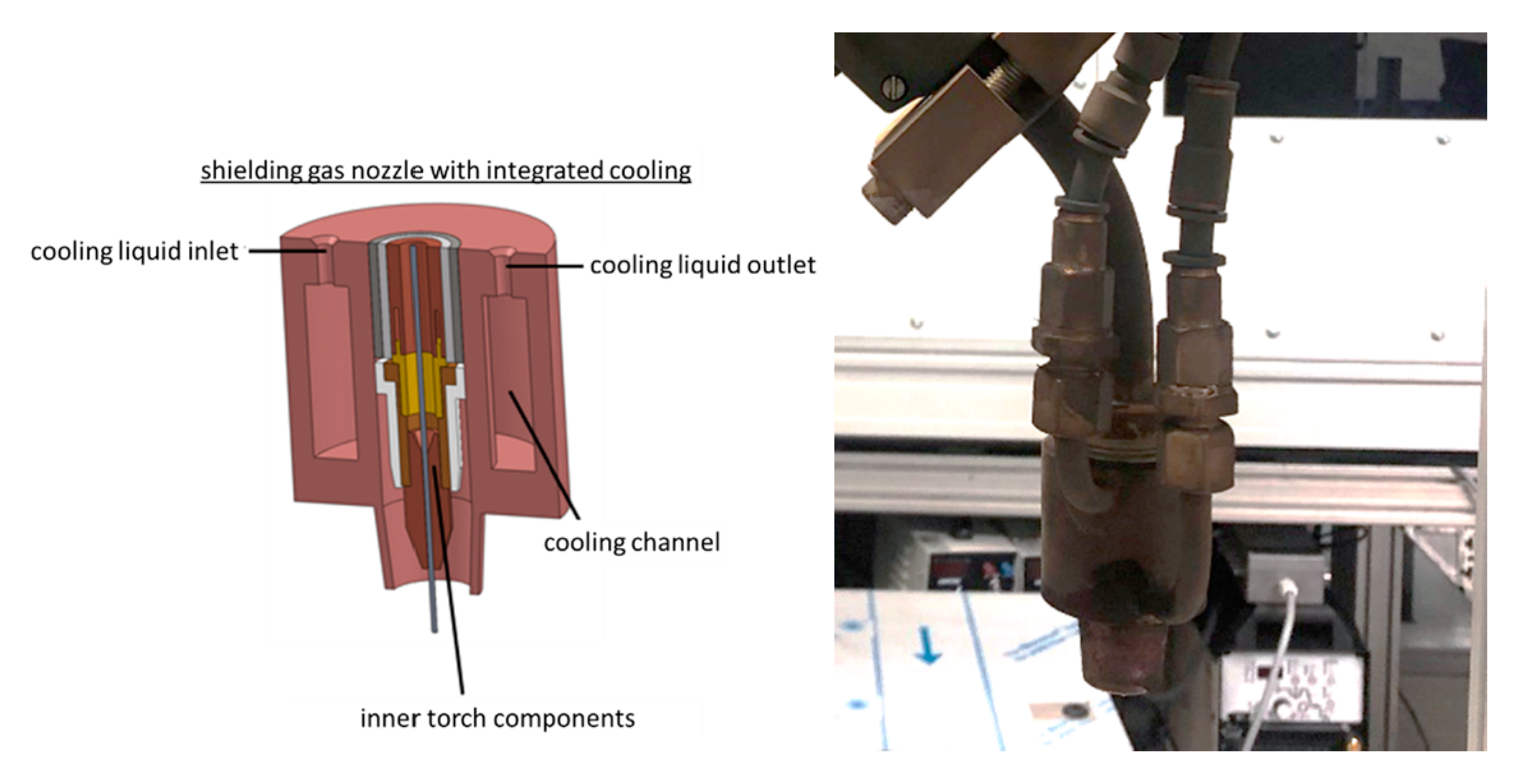
3. Experimental Setup
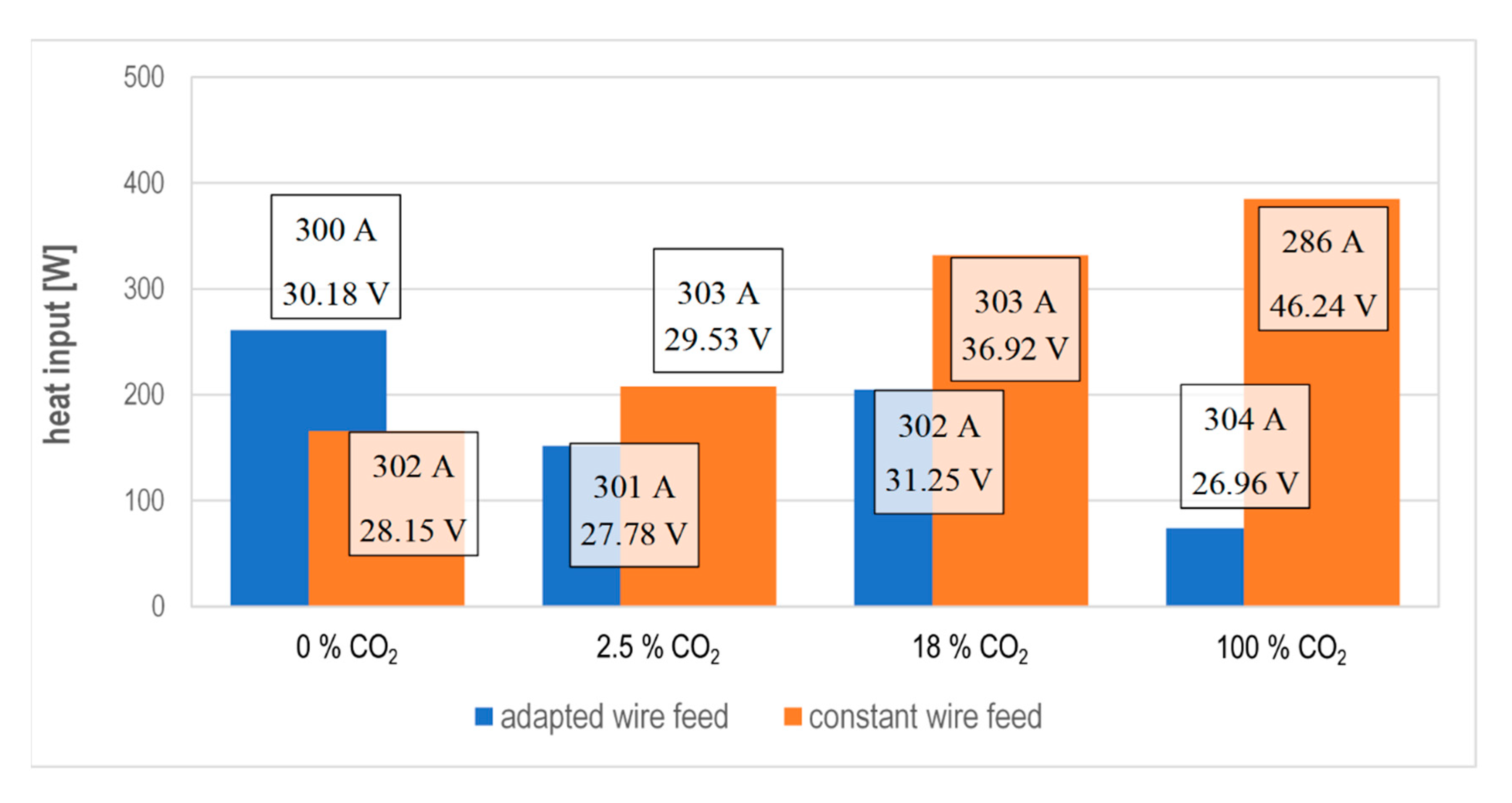
- Measurement series 1: adjusted wire feed (constant voltage correction);
- Measurement series 2: adjusted voltage correction (constant wire feed).
4. Heat Input with Adjusted Wire Feed Rate
4.1. Parameter
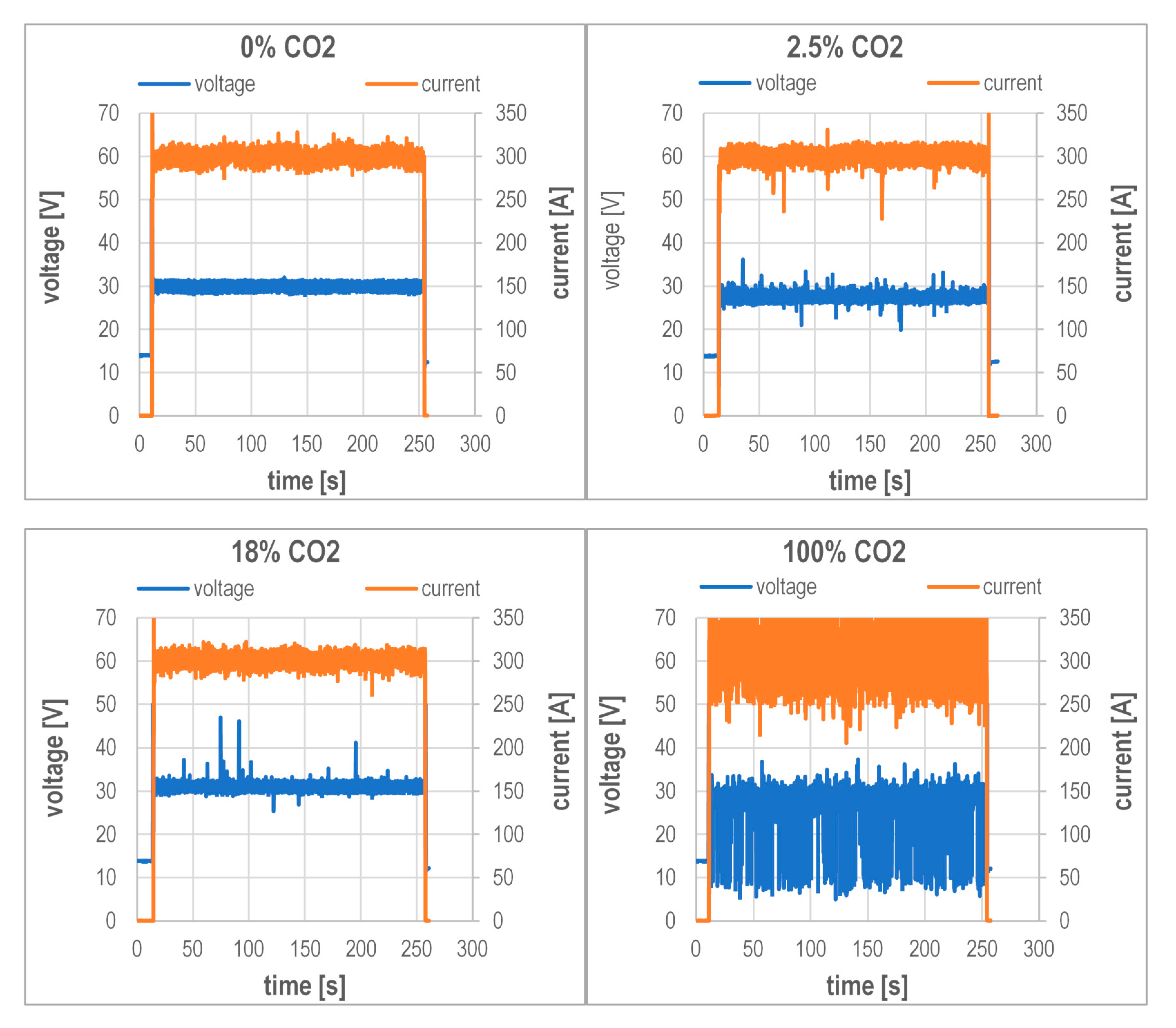
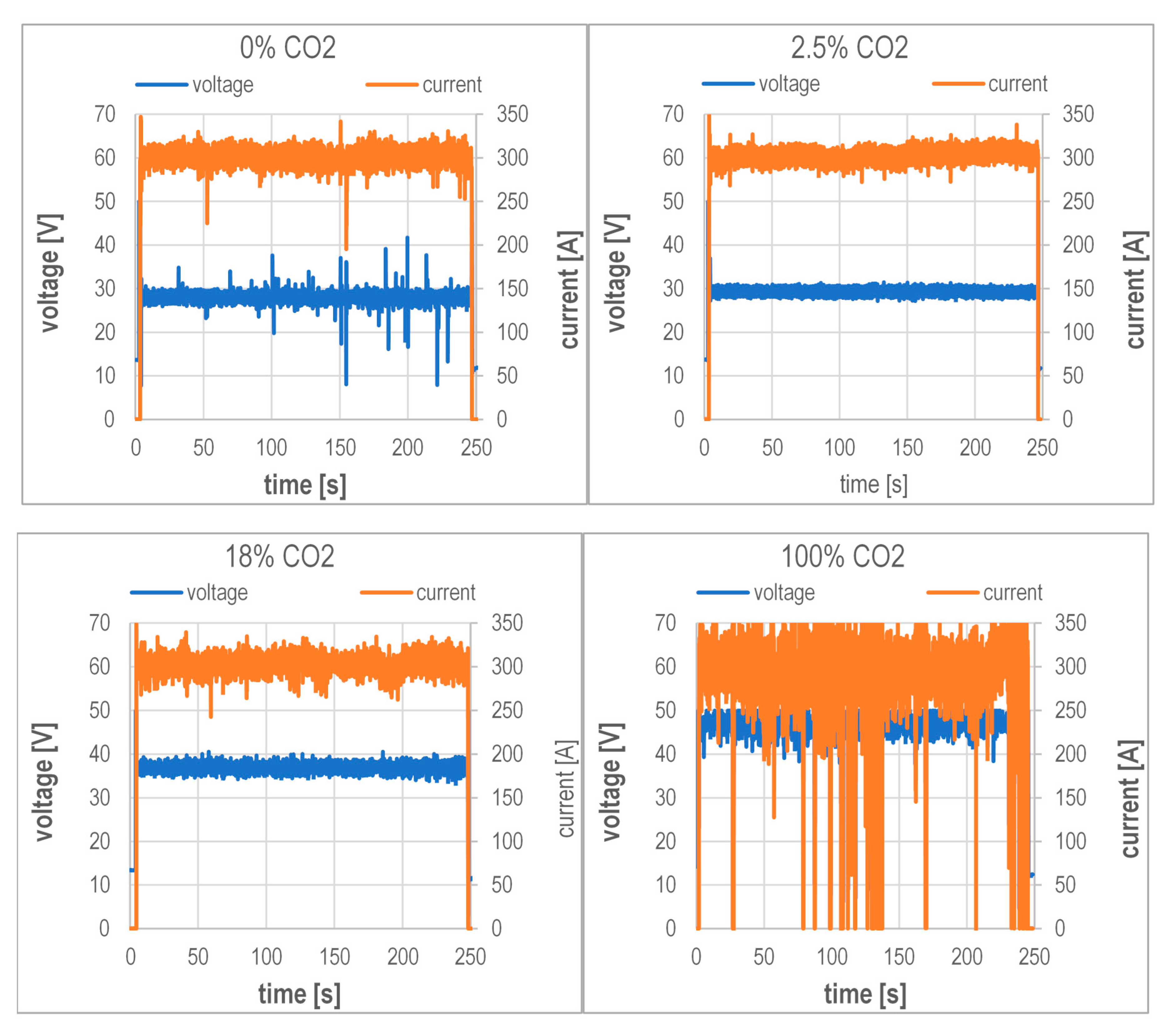
4.2. Current and Voltage Measurement
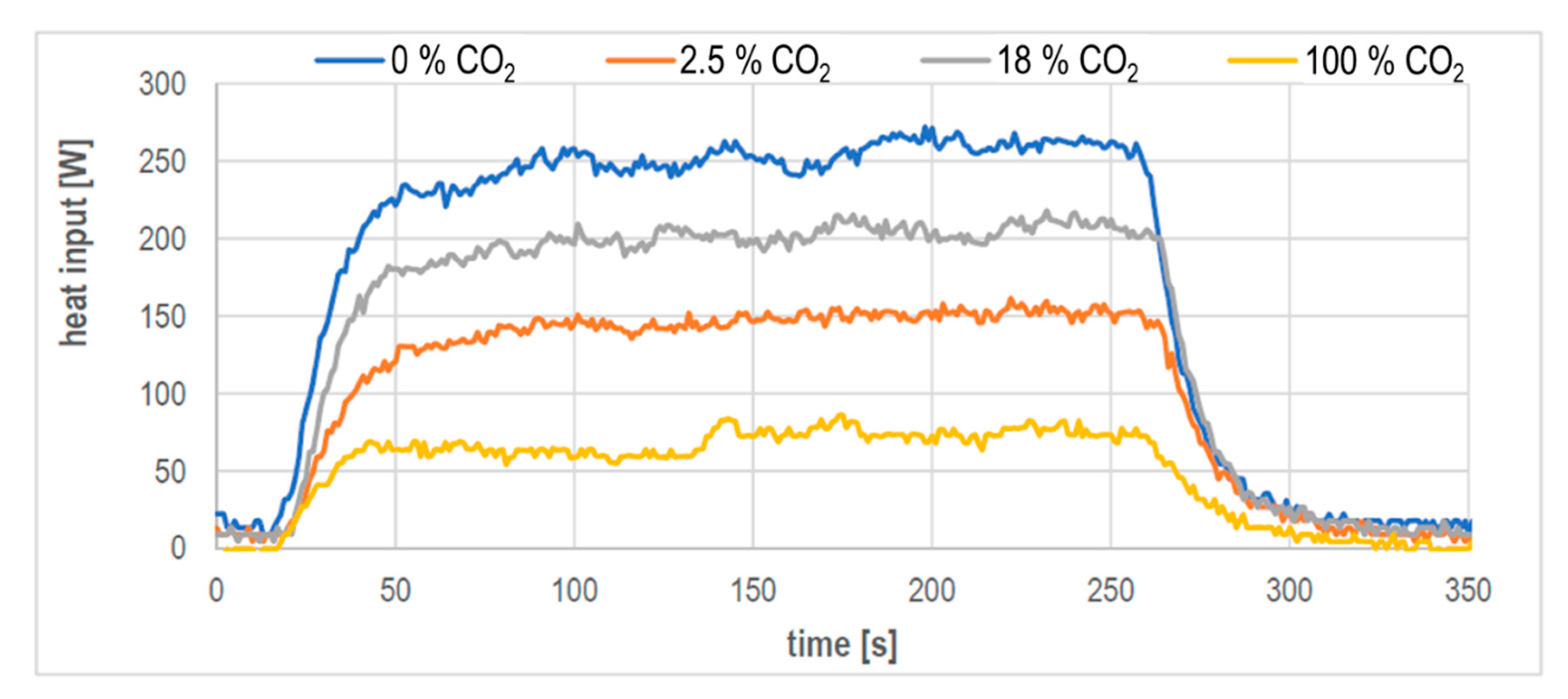
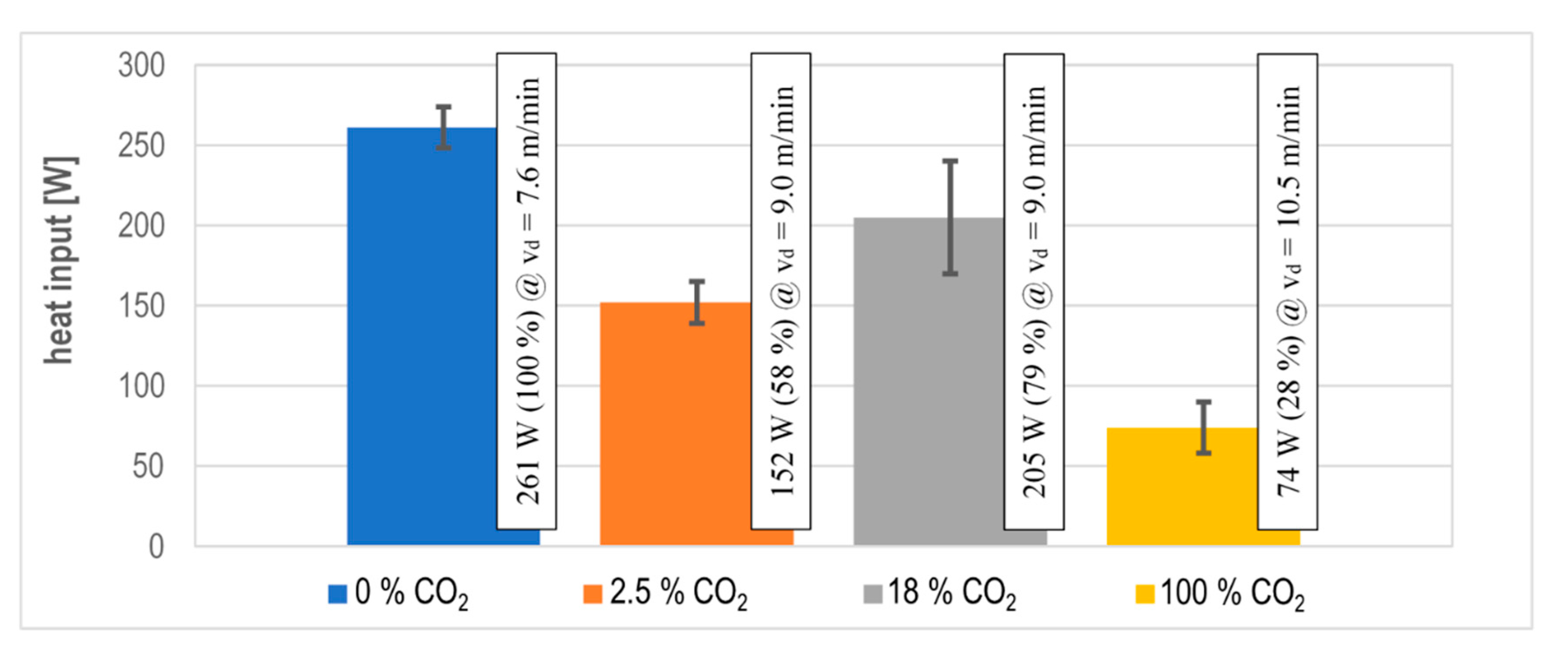
4.3. Heat Input Measurement
4.4. Interim Summary
5. Heat Input with Constant Wire Feed Rate
5.1. Parameter
5.2. Current and Voltage Measurement
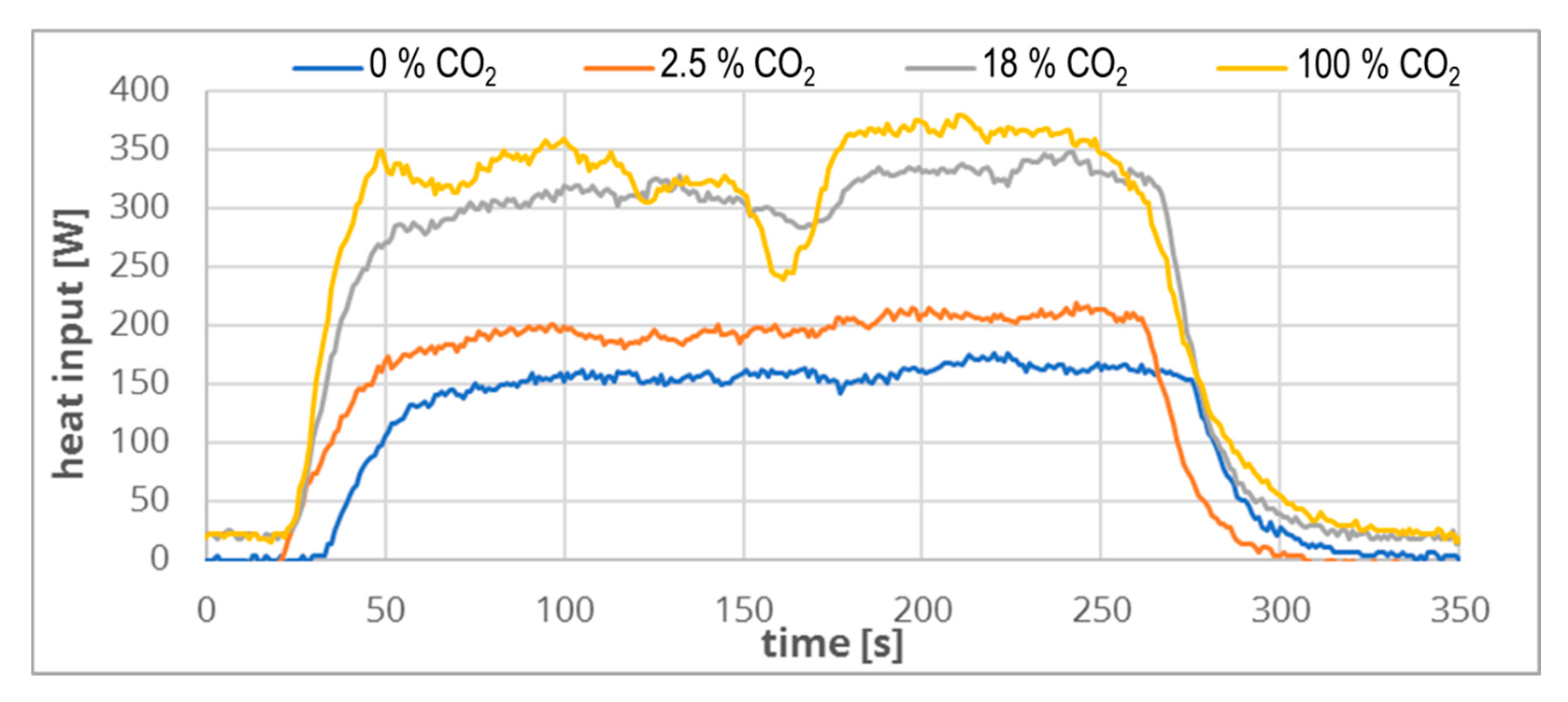
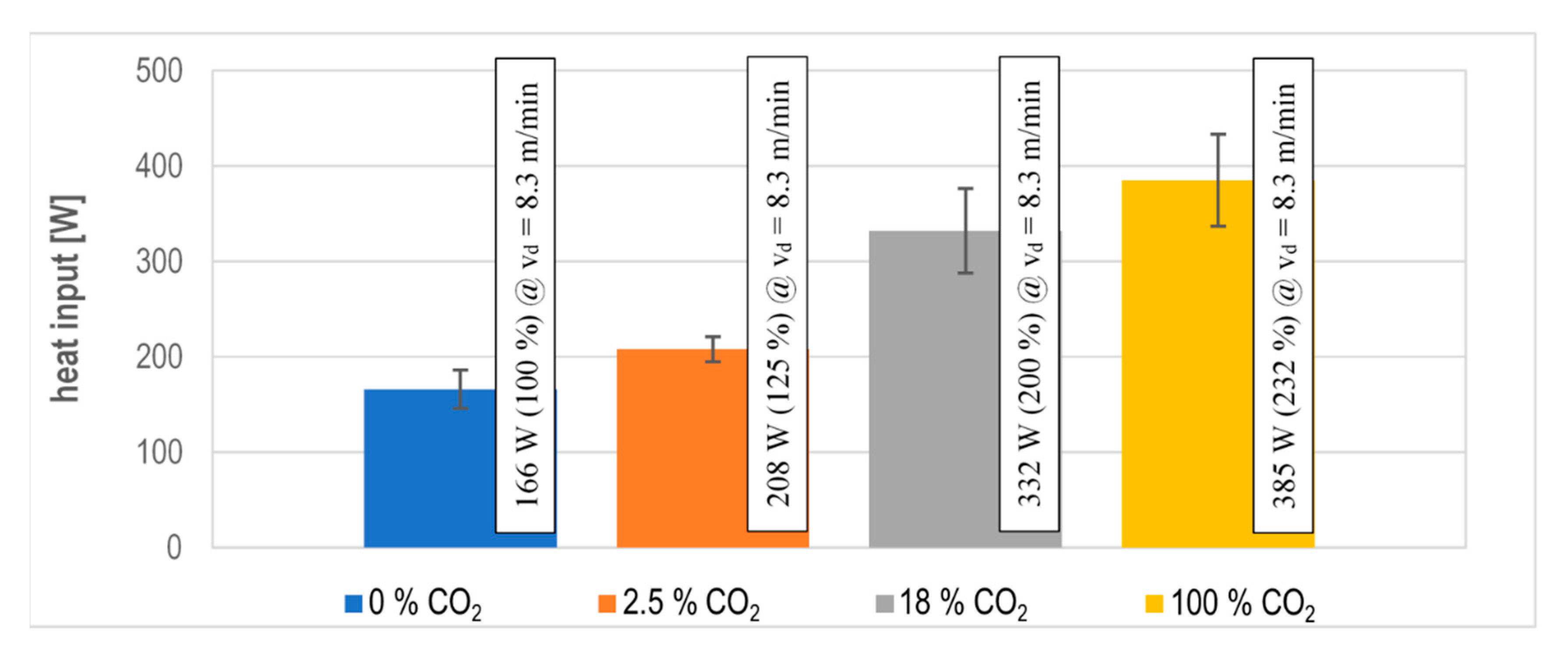
5.3. Heat Input Measurement
6. Summary
Author Contributions
Funding
Conflicts of Interest
References
- Bleck, W.; Moeller, E. (Eds.) Handbuch Stahl: Auswahl, Verarbeitung, Anwendung; Carl Hanser Verlag GmbH & Co. KG: München, Germany, 2017; p. 240. ISBN 978-3-446-44961-9. [Google Scholar] [CrossRef]
- Mvola, B.; Kah, P. Effects of Shielding gas Control: Welded Joint Properties in GMAW Process Optimization. Int. J. Adv. Manuf. Technol. 2017, 88, 2369–2387. [Google Scholar] [CrossRef]
- Matthes, K.-J.; Schneider, W. (Eds.) Schweißtechnik: Schweißen Von metallischen Konstruktionswerkstoffen, 6th ed.; Carl Hanser Verlag GmbH & Co. KG: München, Germany, 2016; ISBN 978-3-446-44561-1. [Google Scholar]
- Dilthey, U. Schweißtechnische Fertigungsverfahren 1: Schweiß-und Schneidtechnologien, 3rd ed.; Springer: Berlin, Germany, 2006; p. 68. ISBN 3-540-21673-1. [Google Scholar]
- Kah, P.; Martikainen, J. Influence of shielding gases in the welding of metals. Int. J. Adv. Manuf. Technol. 2013, 64, 1411–1421. [Google Scholar] [CrossRef]
- Füssel, U. Steigerung der Wirtschaftlichkeit der MSG-Schweißprozesse durch Konsequente Nutzung der Potentiale Von Schutzgasen; AiF Schlussbericht. IGF 17431 N/DVS-Nr. 03.106; TU Dresden: Dresden, Germany, 2014; Available online: https://tu-dresden.de/ing/maschinenwesen/if/fue/ressourcen/dateien/lichtbogenprozesse/projekte-_datei/AiF_17.431__Abschlussbericht_MSG_Schutzgase (accessed on 20 November 2020).
- Alexander Binzel Schweisstechnik GmbH & Co. KG. MIG/MAG-Schweißbrenner MB EVO PRO; Alexander Binzel Schweisstechnik GmbH & Co. KG: Buseck, Germany, 2020; Available online: https://www.binzel-abicor.com/DE/deu/produkte/manuell/migmag-schweissbrenner/schweissbrenner-mb-evo-pro/ (accessed on 2 July 2020).
- Alexander Binzel Schweisstechnik GmbH & Co. KG. MIG/MAG-Schweißbrenner MB ERGO; Alexander Binzel Schweisstechnik GmbH & Co. KG: Buseck, Germany, 2020; Available online: https://www.binzel-abicor.com/DE/deu/produkte/manuell/migmag-schweissbrenner/schweissbrenner-mb-ergo// (accessed on 9 September 2020).
- Haelsig, A.; Kusch, M.; Mayr, P. Calorimetric analyses of the comprehensive heat flow for gas metal arc welding. Weld. World 2015, 59, 191–199. [Google Scholar] [CrossRef]
- Murphy, A.B.; Arundelli, C.J. Transport coefficients of argon, nitrogen, oxygen, argon-nitrogen, and argon-oxygen plasmas. Plasma Chem. Plasma Process. 1994, 14, 1572–8986. [Google Scholar] [CrossRef]
- Yang, A.; Liu, Y.; Sun, B.; Wang, X.; Cressault, Y.; Zhong, L.; Rong, M.; Wu, Y.; Niu, P. Thermodynamic properties and transport coefficients of high-temperature CO2 thermal plasmas mixed with C2F4. J. Phys. D Appl. Phys. 2015, 48, 495202. [Google Scholar] [CrossRef]
- Kozakov, R.; Gött, G.; Schöpp, H.; Uhrlandt, D.; Schnick, M.; Häßler, M.; Füssel, U.; Rose, S. Spatial structure of the arc in a pulsed GMAW process. J. Phys. D Appl. Phys. 2012, 46, 224001. [Google Scholar] [CrossRef]
- Wilhelm, G.; Kozakov, R.; Gött, G.; Schöpp, H.; Uhrlandt, D. Behaviour of the iron vapour core in the arc of a controlled short-arc {GMAW} process with different shielding gases. J. Phys. D Appl. Phys. 2012, 45, 085202. [Google Scholar] [CrossRef]
- Hannachi, R.; Ben Nasr, S.; Cressault, Y.; Teulet, P.; Béji, L. Net emission coefficient of complex thermal plasmas used in {SWNT} synthesis. J. Phys. D Appl. Phys. 2018, 52, 095203. [Google Scholar] [CrossRef]
- Cressault, Y.; Teulet, P.; Gonzalez, J.J.; Gleizes, A.; Robin-Juan, P. Transport and radiative properties of CO2 arc plasma: Application for circuit-breaker modelling. In Proceedings of the XVIth Symposium on Physics of Switching Arc, Brno University of Technology, Brno, Česká Republika, 2005; pp. 46–49. Available online: https://www.researchgate.net/publication/261994037_Transport_and_radiative_properties_of_CO2_arc_plasma_Application_for_circuit-breaker_modelling/citations (accessed on 20 November 2020).
- Wagner, R.; Siewert, E.; Schein, J.; Hussary, N.; Jäckel, S. Shielding gas influence on emissions in arc welding. Weld. World 2018, 62, 647–652. [Google Scholar] [CrossRef]


| Welding Position According to DIN EN ISO 6947 | Flat Position | |
|---|---|---|
| type of welding | Overlap joint | |
| droplet transfer | mainly free of short circuits (determined short circuit time in the results) | |
| wire diameter | [mm] | 1.2 |
| welding current | [A] | 300 |
| voltage correction | [V] | 1 |
| wire feed | [m/min] | variable |
| wire material | G3Si1/DIN 8559: SG2/AWS: A5.18 | |
| power supply | direct current, not pulsed, wire positive | |
| contact tip distance | [mm] | 7 |
| welding speed | [mm/s] | 12 |
| welding time | [min] | ~4 |
| weld seam length | [m] | ~3 |
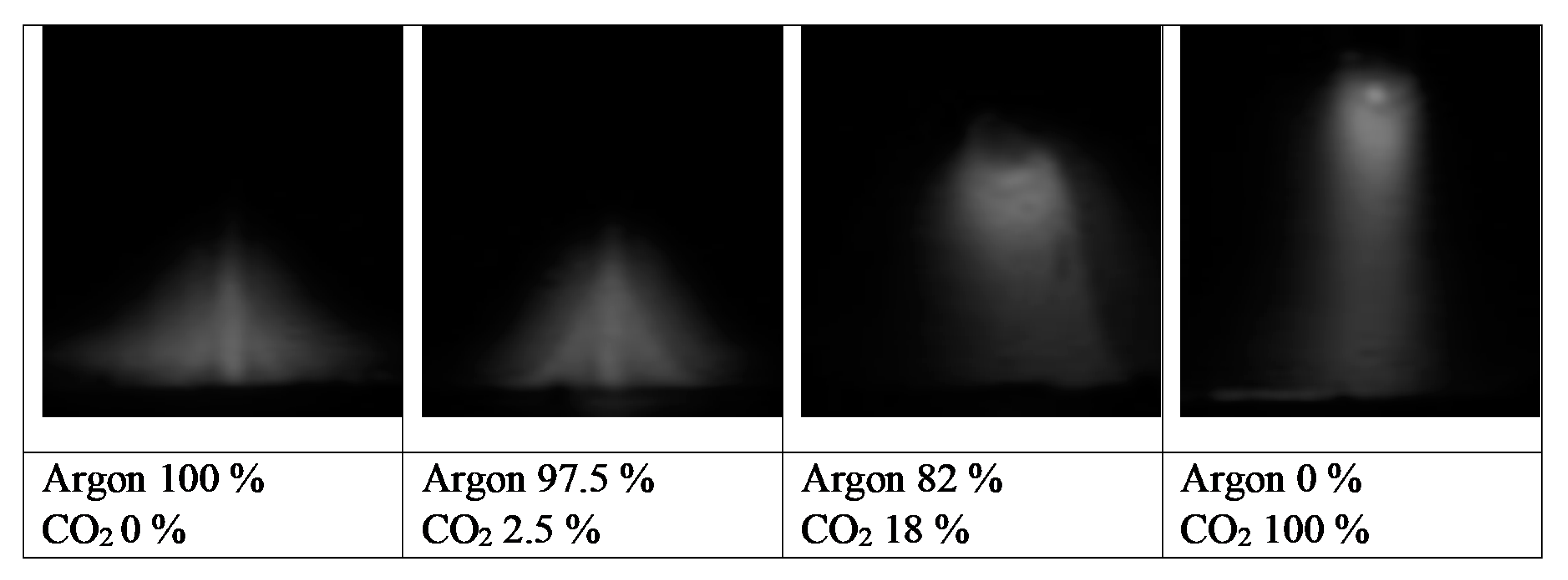
| shielding gas composition | 100% Argon | |
| Argon 97.5% CO2 2.5% | ||
| Argon 82% CO2 18% | ||
| 100% CO2 | ||
| flow rate of the shielding gas | [l/min] | 20 |
| flow rate of cooling water for calorimetry | [l/min] | 1.7 |
| Shielding Gas | Argon 100% CO2 0% | Argon 97.5% CO2 2.5% | Argon 82% CO2 18% | Argon 0% CO2 100% |
|---|---|---|---|---|
| Wire feed [m/min] | 7.6 | 9.0 | 9.0 | 10.5 |
| Short circuit time [%] | 0 | 0 | 0 | 10 |
| average current [A] | 300 | 301 | 302 | 304 |
| average voltage [V] | 30.18 | 27.78 | 31.25 | 26.96 |
| average power [W] | 9050 | 8360 | 9440 | 8200 |
| Shielding Gas | Argon 100% CO2 0% | Argon 97.5% CO2 2.5% | Argon 82% CO2 18% | Argon 0% CO2 100% |
|---|---|---|---|---|
| Voltage correction [V] | −4 | −2.5 | 4.9 | 14.9 |
| Wire feed [m/min] | 8.3 | 8.3 | 8.3 | 8.3 |
| Short circuit time [%] | 0 | 0 | 0 | 0 |
| average current [A] | 302 | 303 | 303 | 286 |
| average voltage [V] | 28.15 | 29.53 | 36.92 | 46.24 |
| average power [W] | 8500 | 8950 | 11,190 | 13,220 |
Publisher’s Note: MDPI stays neutral with regard to jurisdictional claims in published maps and institutional affiliations. |
© 2020 by the authors. Licensee MDPI, Basel, Switzerland. This article is an open access article distributed under the terms and conditions of the Creative Commons Attribution (CC BY) license (http://creativecommons.org/licenses/by/4.0/).
Share and Cite
Lohse, M.; Trautmann, M.; Füssel, U.; Rose, S. Influence of the CO2 Content in Shielding Gas on the Temperature of the Shielding Gas Nozzle during GMAW Welding. J. Manuf. Mater. Process. 2020, 4, 113. https://doi.org/10.3390/jmmp4040113
Lohse M, Trautmann M, Füssel U, Rose S. Influence of the CO2 Content in Shielding Gas on the Temperature of the Shielding Gas Nozzle during GMAW Welding. Journal of Manufacturing and Materials Processing. 2020; 4(4):113. https://doi.org/10.3390/jmmp4040113
Chicago/Turabian StyleLohse, Martin, Marcus Trautmann, Uwe Füssel, and Sascha Rose. 2020. "Influence of the CO2 Content in Shielding Gas on the Temperature of the Shielding Gas Nozzle during GMAW Welding" Journal of Manufacturing and Materials Processing 4, no. 4: 113. https://doi.org/10.3390/jmmp4040113
APA StyleLohse, M., Trautmann, M., Füssel, U., & Rose, S. (2020). Influence of the CO2 Content in Shielding Gas on the Temperature of the Shielding Gas Nozzle during GMAW Welding. Journal of Manufacturing and Materials Processing, 4(4), 113. https://doi.org/10.3390/jmmp4040113