Article

Localized Laser Dispersing of Titanium-Based Particles for Improving the Tribological Performance of Hot Stamping Tools

1
Institute of Manufacturing Technology, Friedrich-Alexander-Universität Erlangen-Nürnberg, Egerlandstraße 13, 91058 Erlangen, Germany
2
Federal Institute for Materials Research and Testing, Unter den Eichen 87, 12205 Berlin, Germany
3
Institute for Machine Tools and Factory Management, Technische Universität Berlin, Pascalstraße 8–9, 10587 Berlin, Germany
*
Author to whom correspondence should be addressed.
J. Manuf. Mater. Process. 2020, 4(3), 68; https://doi.org/10.3390/jmmp4030068
Submission received: 18 June 2020 / Revised: 2 July 2020 / Accepted: 3 July 2020 / Published: 8 July 2020

Abstract

:
Within the scope of this work, a new surface engineering technology named laser implantation has been investigated, in order to improve the tribological performance of hot stamping tools. This technique is based on manufacturing highly wear-resistant, separated, and elevated microfeatures by embedding hard ceramic particles into the tool surface via pulsed laser radiation. Hence, the topography and material properties of the tool are modified, which influences the thermal and tribological interactions at the blank-die interface. To verify these assumptions and to clarify the cause–effect relations, different titanium-based particles (TiB2, TiC, TiN) were laser-implanted and subsequently analyzed regarding to their geometrical shape and mechanical properties. Afterwards, quenching tests as well as tribological experiments were carried out by using titanium-diboride as the most promising implantation material for reducing the tribological load due to high hardness value of the generated implants. Compared to conventional tooling systems, the modified tool surfaces revealed a significantly higher wear resistance as well as reduced friction forces while offering the possibility to adjust the thermal interactions at the blank-die interface. Based on these results, a tailored tool surface modification can be pursued in future research work, in order to enhance the effectiveness of the hot stamping technology.

1. Introduction

1.1. Hot Stamping of Ultra High-Strength Steel

In recent years, lightweight design has become a major forward looking topic in the automotive industry, to meet the governmental CO2 emissions regulations as well as to fulfill the growing customers’ demands for fuel efficient vehicles with high safety standards. By substituting conventional steel grades with ultra-high-strength steel (UHSS), the sheet thickness and the weight of body-in-white parts can be decreased without affecting its crashworthiness [1]. However, high-strength materials are characterized by large springback and limited formability, which in turn requires the application of temperature-assisted forming operations [2]. Against this background, hot stamping has been established as a key technology for lightweight construction, allowing the fabrication of safety-related car body components, such as B-pillars or cross members, with a high strength-to-weight ratio [3]. Hot stamping is characterized as a non-isothermal forming process, which can be executed in two different ways [4]. In direct hot stamping, pre-cut sheets are initially heated above 850 °C for several minutes in an external furnace. Afterwards, the semi-finished parts are transferred to a water-cooled press and subsequently formed and quenched at the same time. In a final step, finishing operations, like cutting or sandblasting are carried out [5]. The indirect process route, in contrast, is characterized by an additional cold forming operation prior to the heat treatment step, to generate geometrical complex structures with superior dimensional accuracy. By pursuing this strategy, however, increasing process cycle times are required, which implies higher production costs as well. Basically, hot stamped parts are made out of 22MnB5 boron–manganese steel sheets (1.5528), revealing a ferritic–pearlitic microstructure with an ultimate tensile strength of 800 MPa as-delivered condition. The heat treatment above the material specific AC3 temperature as well as the combined forming and quenching step are leading to a phase transformation from austenitic into martensitic microstructure provided that a minimum cooling rate of 27 K/s is exceeded [6]. As a result, geometrical complex parts with increased ultimate tensile strength up to 1500 MPa are generated [3]. To avoid both scaling and decarburization during the hot stamping process, the surface of the sheet metal has to be protected with a coating system. For this purpose, an AlSi layer is commonly applied on the blank for direct hot stamping, whereas a Zn-based coating is mainly used within indirect hot stamping due to its improved forming behavior at room temperature [7]. However, studies from Venema et al. [8] and Ghiotti et al. [9] revealed, that both coating systems cannot withstand the alternating thermo-mechanical load conditions during the combined forming and quenching step. Consequently, excessive tool wear appears within short production periods, which negatively impacts the workpiece quality and the tool lifetime [10]. Moreover, the application of conventional lubricant systems is not possible during hot stamping, since blank temperatures above 800 °C occur. Hence, high friction values arise at the blank-die interface, which considerably limit the formability of the hot stamped parts. To counteract these unfavorable tribological conditions, different tool surface modification technologies have been investigated. Vilesaca et al. [11] analyzed the effect of physical vapor deposited (PVD) tool coating systems, in order to reduce the chemical affinity to adhesive wear. Their results revealed that AlCrN and CrN are both appropriate layer materials to reduce the amount of tool-sided wear within hot stamping. In contrast, however, studies from Pelcastre et al. [12] observed high galling tendency and increased tool wear by using AlCrN coating systems at high temperature. Further investigation on TiAlN and diamond-like carbon (DLC) based layers evinced an inadequate resistance to galling as well. Moreover, coating systems have limited usage for industrial applications due to their brittleness at high and frequent thermal cycling, which could lead to stress-induced cracks of the protection layer [13]. Surface texturing is another well-known approach in sheet metal forming to enhance the tribological behavior between tool and blank. This method is based on modifying the geometry of the tool topography, which enables the adjustment of the friction forces at the blank-die interface. Shimatsu et al. [14] investigated the effectiveness of this technique by using laser textured dies under hot stamping condition. Based on a localized laser treatment, defined lower surface features were generated at the tool topography, which could enhance the tribological behavior of the tooling system. To gain this improvement, however, all laser-generated microcavities had to be stored with environmentally harmful MoS2 lubricant prior to the tribological test. Mousavi et al. [15] investigated the effect of protruded surfaces features, in order to reduce the tribological load within lubricant free cold forming operations. Their results reveal that macro- and microtextured dies are leading to a significant improvement of the tribological performance, since the contact area and the material flow between tool and workpiece were locally adjusted. However, the usage of protruded features has not been established within hot stamping due to the low durability of the structures. For this purpose, further technologies have to be investigated, in order to achieve economic, long-term effective, and environmental-friendly benefits.

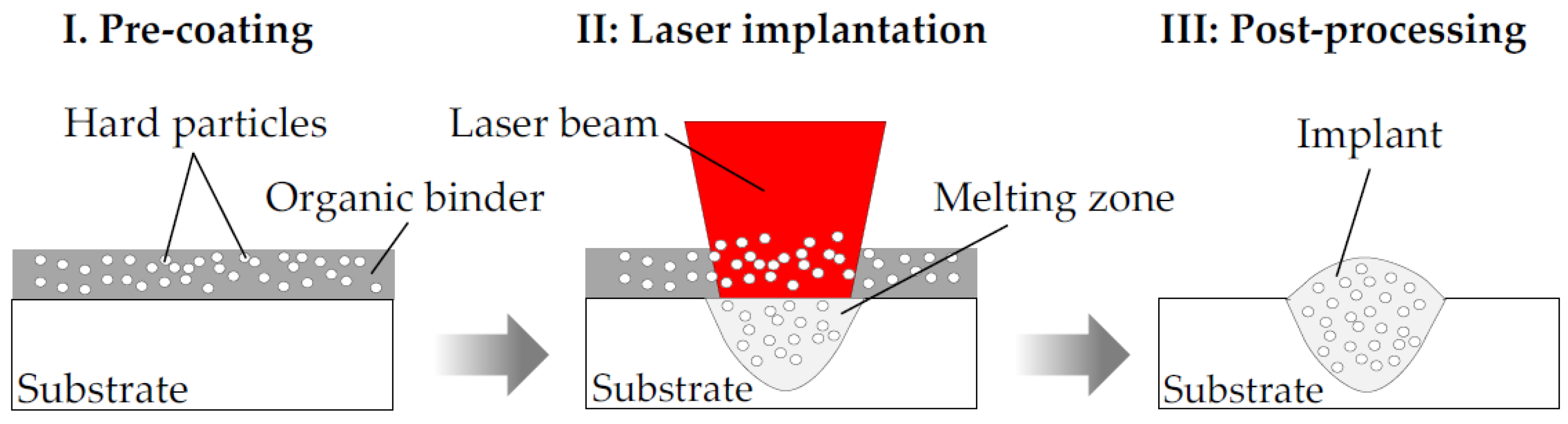
1.2. Laser Implantation Process

The laser implantation process is a promising new surface engineering technology, which combines both currently applied methods for improving the tribological behavior (optimization of tool material properties as well as surface texturing) in one processing step. In this regard, synergetic effects of both approaches are expected, in order to improve the effectiveness and tribological performance of hot stamping tools. The laser implantation technique is based on the generation of dome-shaped and highly wear-resistant microfeatures by embedding hard ceramic particles on tools surfaces via pulsed laser radiation. The geometrical shape and the mechanical properties of the so-called implants are highly controllable by adjusting the pre-coating system and laser parameters. Due to the high flexibility of the laser-system, single separated surface features can be arranged to deterministic pattern and precisely placed at geometrical complex and highly stressed tool surfaces. Hence, the topography and materials properties of the tool along with the thermal and tribological interaction at the blank-die interface are locally modified. The principle of the laser implantation process is shown in Figure 1.
Prior to the laser processing, the substrate material is pre-coated with an organic binder and the hard ceramic particles. Afterwards, the pre-processed surface is locally treated by using a pulsed fiber laser, leading to a local volume increase in micrometer range caused by the finely dispersed particles. In the post-processing step, the remaining pre-coating is removed with ethanol as solvent. Hilgenberg et al. [17] have successfully used the laser implantation process within cold forming operations, in order to enhance the tribological performance of skin-pass rolls. Their results of a twin-disk-test showed, that laser-generated implants were not affected by fatigue failure or wear even after 1.26 × 10⁶ cycles against hardened and tempered 1.2842 counter rolls. For this purpose, a transfer of this surface engineering technology to the hot stamping process is of major interest, to investigate its tribological impact on forming tools, which are exposed to both thermal and mechanical load conditions. However, a suitable selection of the implantation material is an essential prerequisite, in order to obtain tailored, defect-free and highly wear resistant surface features. In this regard, different titanium-based hard ceramic particles (TiB2, TiC, and TiN) were embedded on hot working tool steel specimens, in order to gain in-depth knowledge about the geometrical shape and mechanical properties of the laser-generated spots. Afterwards, quenching tests as well as tribological experiments were carried out by using laser-implanted and unmodified tooling systems, to clarify the cause-effect relations and to qualify the thermal and tribological behavior of the surface features under hot stamping conditions.

2. Materials and Methods

2.1. Localized Dispering of Hard Ceramic Particles

2.1.1. Tool Steel and Implantation Material

The hot working tool steel X38CrMoV5-3 (1.2367) has been chosen as substrate, since this steel grade is mainly used for industrial hot stamping applications. Prior to laser implantation, a multistep heat-treatment was conducted, in order to achieve an industry-related tool hardness to withstand the high thermo-mechanical stresses during hot stamping. To qualify the dispersion behavior, specimens with dimensions of 30 mm × 20 mm × 10 mm were cut, hardened at 1040 °C for 30 min, cooled in oil and finally tempered three times at 510 °C for 2 h. Afterwards, the chemical composition of the heat-treated samples was determined by means of emission spectrometry analysis (OES-spectrometer SPECTROTEST, Kleve, Germany). In addition, optical measurements, hardness (Zwick 3202, Ulm, Germany) and X-ray diffraction (Stresstech G3, Rennerod, Germany) tests were performed, to analyze the mechanical properties of the specimens. Against this background, the optical micrograph of the tool steel revealed a martensitic structure without any visible carbides. Moreover, an average hardness value of 602 HV1 and almost no retained austenite was detected. Further details of the material properties are listed in Table 1.
As implantation materials, titanium diboride (TiB2), titanium carbide (TiC) and titanium nitride (TiN) have been chosen in powder form. All kind of hard ceramic particles offer great potential for improving the tribological performance of highly stressed tool surfaces due to their ceramic properties and high melting temperatures, which are beneficial to reduce the amount tool-sided wear as well as to resist thermo-mechanically alternating load conditions. To verify these assumptions, however, a detailed analysis and comparison of the resulting implant properties has to be performed prior to the tribological experiments, to evaluate the geometrical and mechanical impact of all titanium-based materials. Within this work, the grain size distribution was determined by laser granulometry measurement (Mastersizer 2000, Malvern Instrument GmbH, Kassel, Germany). In addition, the particle shape was analyzed via scanning electron microscope (SEM, Tescan Vega V3, Fuveau, France). The results of the measurements along with the thermo-mechanical properties of all materials are shown in Table 2.

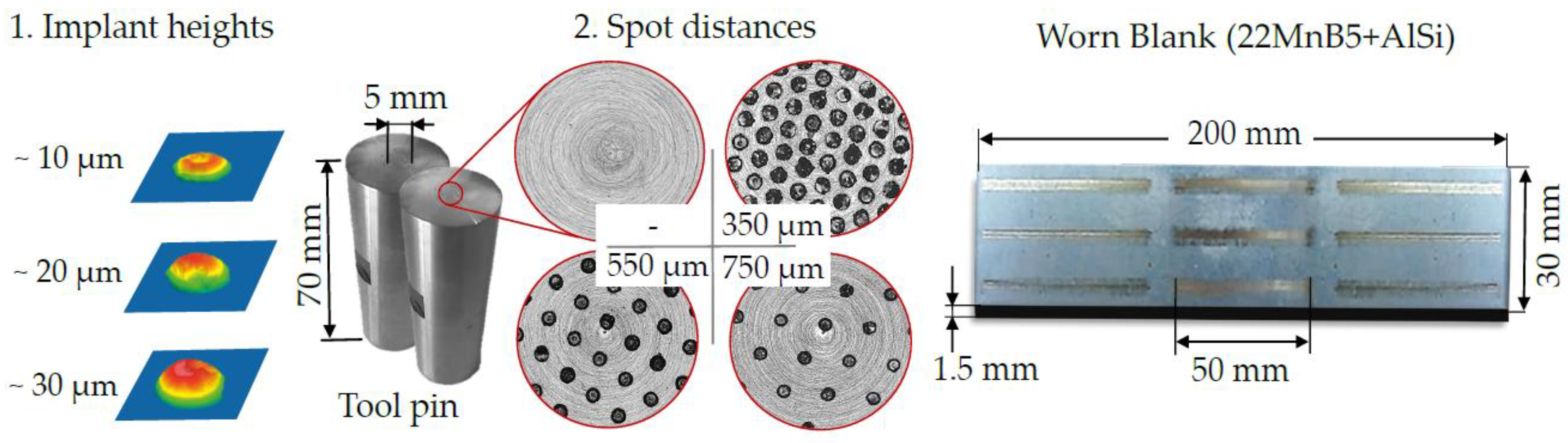
2.1.2. Experimental Setup and Laser-Processing

As preparation step, the surfaces of hot working tool samples were spray coated by using a slurry containing 6 g hard particles, 0.5 g organic binder (Mowital 30 H) and 8 mL ethanol as solvent. After drying on air for 24 h, all pre-coated specimens exhibited a coating thickness hc of 100 ± 10 µm with a hard particle share of ~95%. For the laser implantation process, a pulsed Yb:YAG fiber laser (YLS-600/6000-QCW-ACY15, IPG Photonics, Burbach, Germany) with a wavelength of λ = 1070 nm and a Gaussian intensity distribution was used. The beam optics (BIMO HIGHYAG) was adjusted perpendicular to the pre-coated substrate surface, while Argon was applied as shielding gas (22 L/min). After laser processing, the remaining pre-coating was carefully removed with ethanol in an ultrasonic bath. The experimental series were split into two main parts, the characterization of the implantation behavior by using different hard ceramic particles and the subsequent modification of hot stamping tooling systems. Within the first part, the particle-matrix interaction was studied by using different laser settings, in order to ensure the manufacturing of highly wear-resistant and defect-free surface features with high process reliability. In this context, the pulse power pp was varied between 30 W–180 W and the pulse duration tp was adjusted from 3 to 15 ms. A constant focal dimeter dB of 105 µm was used within all experiments. Afterwards, the resulting microstructure of the laser-generated spots was investigated by using backscattered electron microscopy (Tescan Vega V3, Fuveau, France). In addition, white light interferometry (Zygo NextView, Weiterstadt, Germany) and hardness measurements according to DIN EN ISO 6507-1 (Zwick 3202, Ulm, Germany) were carried out, to determine the geometrical shape and the mechanical properties of the implanted zones. X-ray diffraction (XRD) analysis were finally performed to quantify the average retained austenite content (γR) of the microfeatures. Based on these results, suitable hard ceramic particles and laser parameters were utilized in a second part, in order to generate defect-free microfeatures on the topographies of the hot stamping tooling systems.

2.2. Tribological and Thermal Analysis

2.2.1. Modified Pin-on-Disk Test

A modified pin-on-disk test was used for qualifying the wear and friction behavior of unmodified and laser-implanted tool surfaces under hot stamping conditions. This wear test rig is characterized by an open tribological system, which enables a continuous flow of unworn sheet metal onto the tool contact area. The testing apparatus is based on a heated metal support, powered by two ceramic heating elements, to ensure a consistent blank temperature during the tribological test. The temperature of the metal support was set to ~800 °C, which corresponds to the initial forming temperature of a hot stamping process [1]. In addition, a tool pin has been mounted on a frame and attached to the industrial robot of type Kuka KR200-3, to apply a defined load and sliding velocity on the workpiece. During the tribological tests, the transmitted normal force FN was quantified with three 2 kN load cells of type C9B (HBM). Moreover, an additional load cell of 1 kN capacity (HBM) has been mounted on the front panel of the wear test rig, in order to determine the friction force FR. Based on these measurements, the friction coefficient µ could be calculated according to Coulomb’s law (FR = µ × FN). Prior to the tribological experiment, the contact area of all mounted tool pins was controlled by means of a pressure indicating film (Fujifilm prescale) to ensure an uniform pressure distribution at the blank-die interface. Afterwards, an AlSi coated 22MnB5 blank has been austenized for 360 s at 930 °C in an external oven. The sheet was subsequently placed on the pre-heated slide and the tribological experiment was carried out within three consecutive steps, starting with the positioning of the tool above the austenized blank surface (I). Afterwards, a constant normal pressure FN was applied, while sliding the pin along predefined paths over the austenized workpiece (II). Finally, the tool moved upwards and the surface was cooled by compressed air to consider the thermal alternating stress of an industrial process (III). This procedure was repeated nine times with a single wear track distance of 50 mm. Each tool configuration was tested with a number of 3 pins and 15 blanks, resulting in an overall sliding distance of 6750 mm. The tribological experiments were performed with a pin velocity of v = 120 mm/s, a contact pressure p = 20 MPa, and a blank temperature of TB = 800 °C, in order to imitate industrial hot stamping settings. The experimental setup as well as the process principle are both shown in Figure 2.
Within the scope of this work, AlSi coated 22MnB5 blanks with a size of 200 mm length, 30 mm width and 1.5 mm thickness have been utilized. The hot working tool steel 1.2367 has been selected as tool material, which was manufactured in cylindrical shaped pins with 70 mm length and 22 mm diameter. At top section, a planar contact area of 5 mm diameter was grinded, in order to ensure the perpendicularity of the pin regarding to the blank topography. For the tribological experiments, unmodified as well as various laser-implanted tool pins have been used, to analyze and compare their tribological performance under hot stamping conditions. In this regard, nine different variants of laser-implanted tool configurations have been generated, which are characterized by different implant heights (10, 20, and 30 µm) and spot distances (350, 550, and 750 µm). Within the planar contact area, all microfeatures have been arranged in hexagonal pattern. The analyzed tool configurations as well as a worn blank topography are exemplary illustrated in Figure 3.

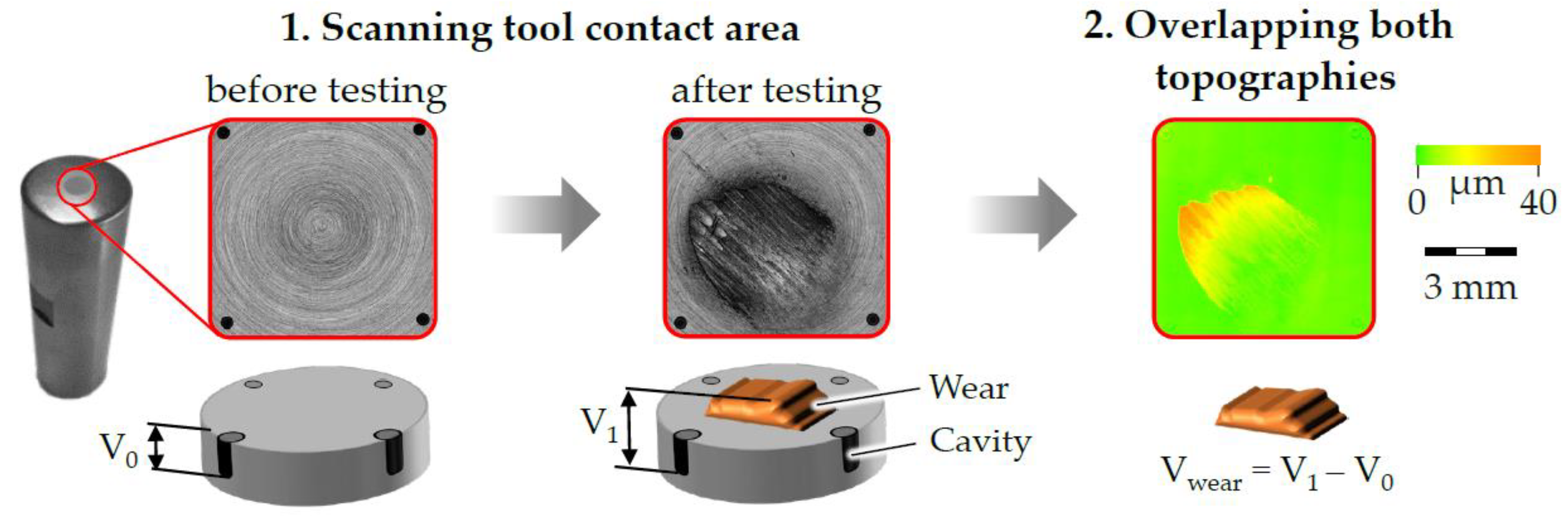
2.2.2. Wear Characterization

The amount of tool-sided wear was quantified by means of an optical measurement method. Each tool topography was analyzed before and after the tribological test, in order to identify the volume difference and the occurring surface wear. For this purpose, the laser-scanning microscope Keyence VK-X200 was used as measuring device for characterizing the unworn and worn tool contact areas. Afterwards, the recorded images of the contact zones were both superimposed by means of the software VK Analyse-Modul (Keyence, Neu-Isenburg, Germany), to determine the resulting geometrical deviation. For a precise calculation of the arising wear, however, an exact alignment of both topographies in height and width must be guaranteed. Against this background, four microcavities (diameter ø = 100 µm, depth d = 30 µm) have been eroded at the pin surface prior to the testing procedure, in order to obtain reference planes for the optical comparison measurement. The depressions were positioned outside the planar contact area in a distance of 7 mm to prevent them from damage or wear. Due to these integrated microcavities, an exact overlapping of both topographies in horizontal and vertical direction could be ensured, which enabled an accurate computation of the of the resulting surface wear. The principle of this measuring method is schematically shown in Figure 4.

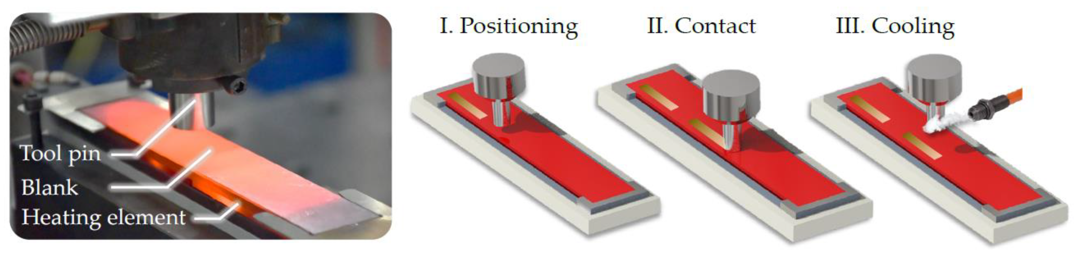
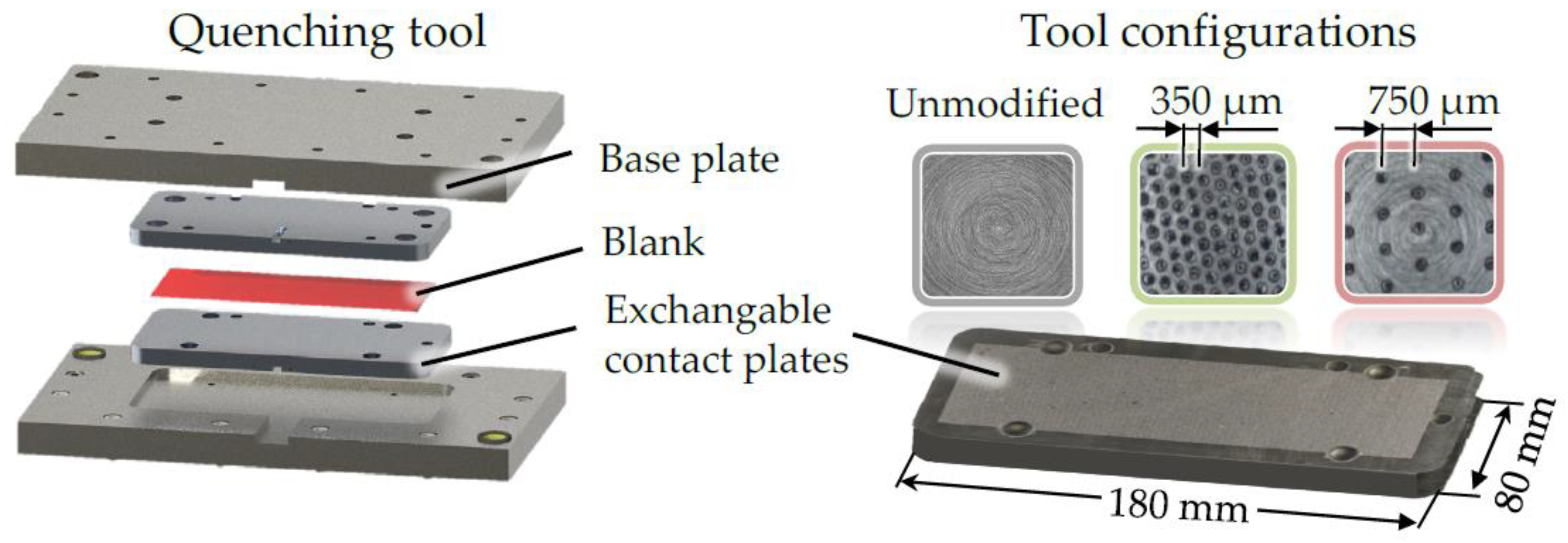
2.2.3. Quenching Test

Since the cooling rate of the tool influences the phase transformation and the mechanical properties of the workpiece, quenching tests were carried out for investigating the thermal performance of laser-implanted tool surfaces. The universal testing machine of type Schenck Trebel RM 400 has been used as testing apparatus, which was equipped with a quenching device. Basically, this tooling system consists of two exchangeable contact plates, which enable the characterization of different surface modifications. In this regard, an unmodified as well as two laser-implanted contact plates with uniform implant heights (~30 µm) but different spot distances (350 and 750 µm) have been utilized for investigating the heat transfer at the blank-die interface. Prior to each testing sequence, an AlSi coated 22MnB5 blank (l = 160 mm, w = 58 mm, and d = 1.5 mm) has been heated up for 360 s at 930 °C in an external furnace. The austenized specimen was subsequently positioned between the contact plates on four spring-seated pins, in order to avoid a premature cooling. By closing both mold halves, a normal pressure of 20 MPa was applied on the workpiece until its core temperature cooled down to room temperature. The blank was equipped with thermocouples of type K, to monitor the time temperature development during cooling. Each tool configuration was tested with a number of three blanks to consider the statistical deviations of the measurements. Based on the recorded temperature curves, the average cooling rates could be calculated and compared. The quenching device as well as the tool configurations are shown in Figure 5. Further details on the tooling setup, which was constructed at the institute of manufacturing technology, can be found in [18].

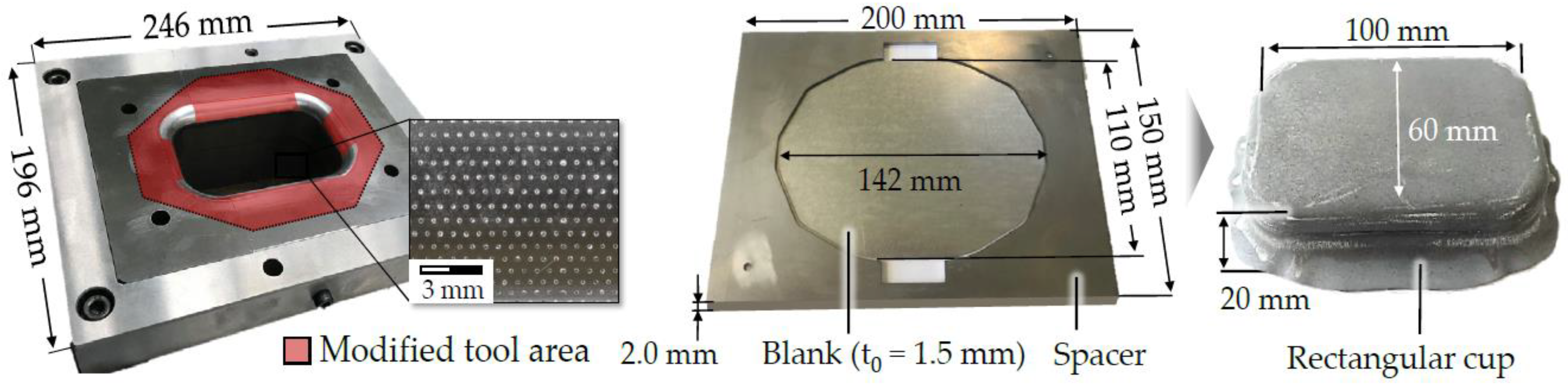
2.2.4. Hot Stamping of Rectangular Cups

The applicability and transferability of the laser implantation process concerning an industry-related tool geometry was qualified by means of deep drawing tests. For this purpose, a laser implanted as well as a conventional die were integrated in the drawing press of type Lasco TSP100S0 for hot stamping fifty rectangular cups each. The tool modification was applied at the transversal and longitudinal tool-sided radii as well as at the flat support surface. The implants were generated in hexagonal pattern within a spot distance of 750 µm and a dome-height of ~30 µm. Figure 6 reveals the modified tooling system along with the corresponding cup geometry.
Prior to the hot stamping process, an AlSi coated 22MnB5 blank has been heated up for 360 s at 930 °C in an external furnace, which was located next to the drawing press. Afterwards, the pre-heated blank was transferred onto the die and the forming operation was subsequently carried out at maximum press velocity of 60 mm/s by using a gap width of 2 mm between punch an die. No initial blank holder force was applied on the austenized workpiece (t0 = 1.5), in order to avoid a premature cooling of the flange area. This technique is conventionally used in hot stamping, to improve the formability of the hot stamped parts. However, a spacer with a thickness of tS = 2 mm has been placed between both mold halves, to ensure a constant clearance and precise positioning of the blanks. This tooling component, which has not been laser-implanted, was used along with the unmodified and modified die. During the tribological test, the punch force was quantified by using an integrated 650 kN load cell (Kistler), to qualify the tribological impact of the surface modifications. Moreover, the sheet thickness distribution of several cups was measured by using the topometric 3D sensor ATOS (GOM Metrology, Braunschweig, Germany) to gain in-depth knowledge regarding the quality of the hot stamped components.

3. Results and Discussion

3.1. Laser Implantation of Titanium-Based Hard Ceramic Particles

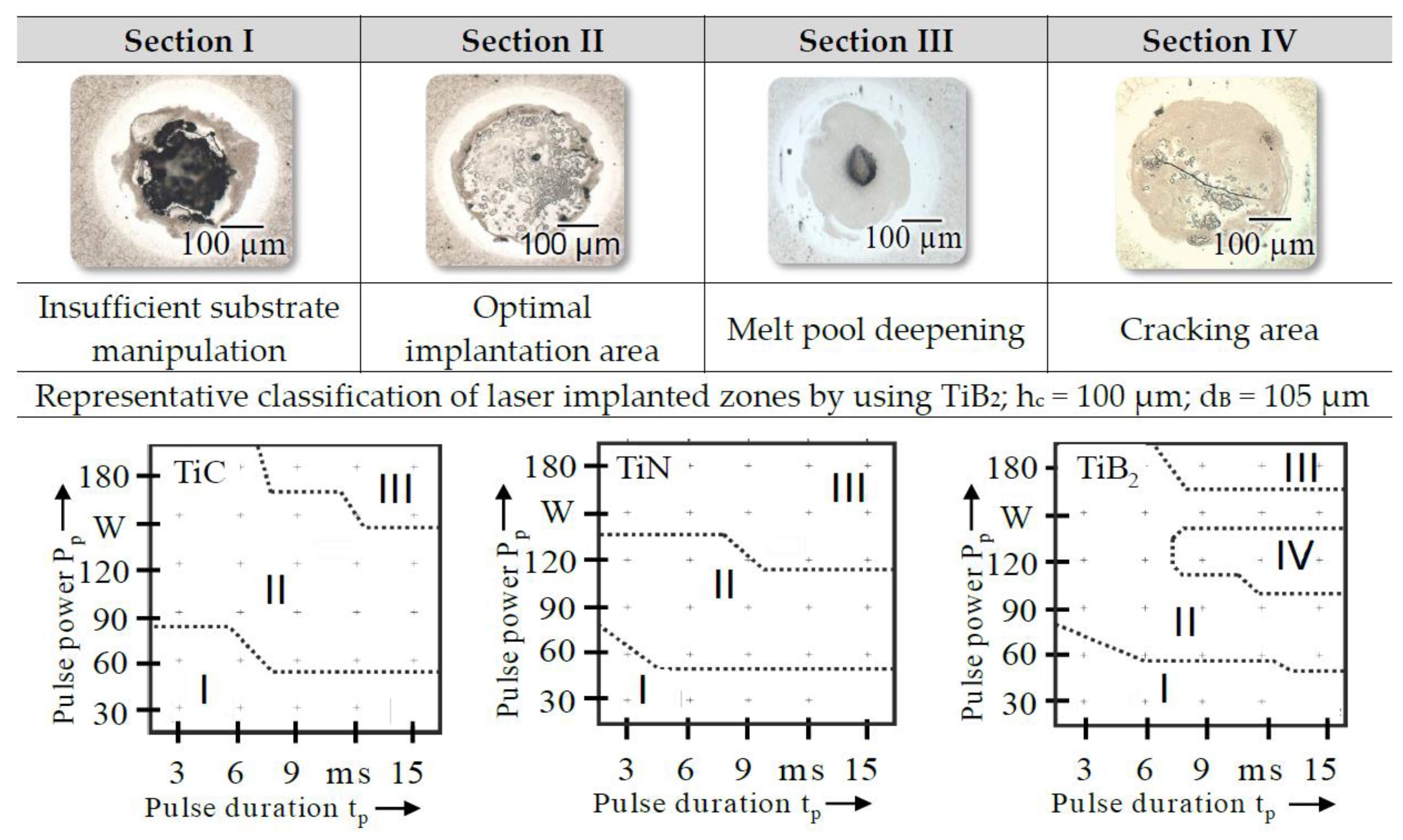
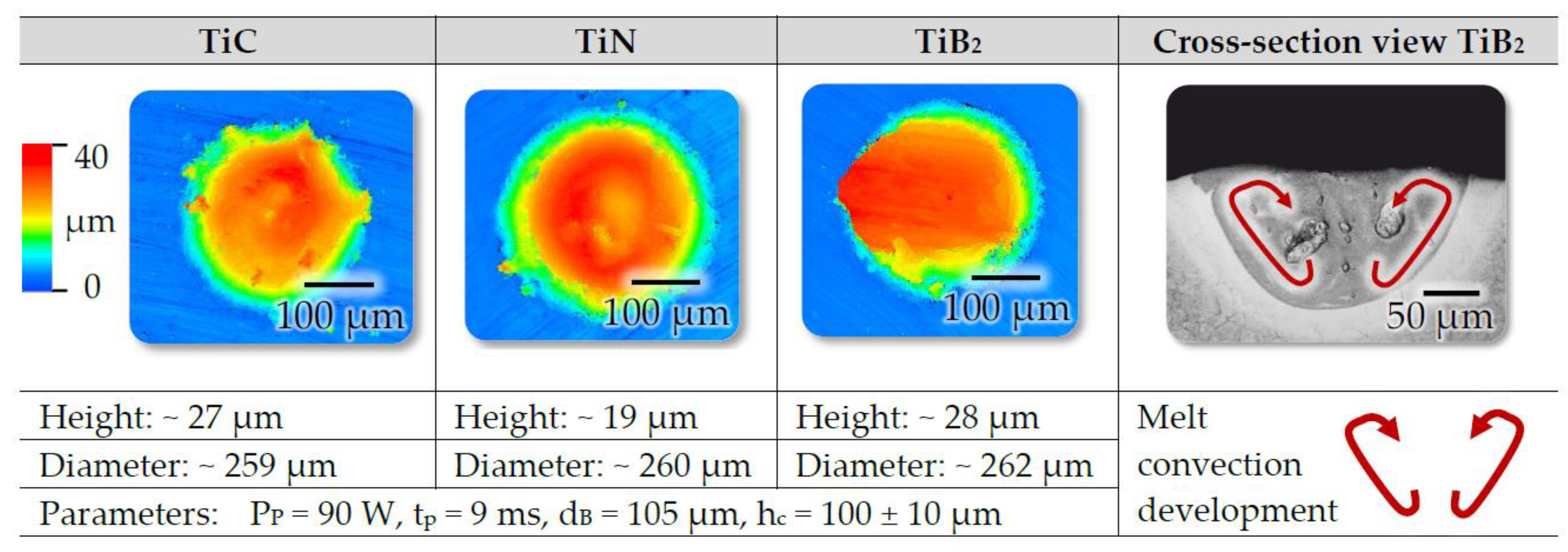
3.1.1. Characterization on the Forming Behavior and Implant Shape

The laser implantation process was performed by using different laser parameters, in order to analyze the effects on the occurring forming behavior. The results revealed that the adjustment of the laser pulse power Pp und pulse duration tp had a significantly influence on the implantation behavior of all titanium-based hard ceramic particles. Therefore, a classification of the laser-generated microfeatures according to their visual appearance has been carried out, which is shown in Figure 7.
The manufactured spots of section I are characterized with an irregular shape and a centered depression in the laser implanted zone (LIZ). Furthermore, elevated but irregular structures were generated. Due to the insufficient laser energy, not enough melt volume could be produced during laser processing, in order to entrap the particles and distribute them into the implanted zones [19]. This behavior has been recognized for all kind of tested particles within a pulse power range up to 60 W. With rising pulse power and pulse duration, an increasing amount of radiated energy will be emitted into the hot working tool steel X38CrMoV5-3 by means of the laser beam. As a result, less till no irregularities arise and more regular, mostly dome-shaped implants are formed. Within section II, a defect-free matrix was observed with a high share of homogenously disturbed particles. Due to the heat of the laser beam, a sintering process was initiated between the titanium-based particles. With further increase of the laser energy, less agglomerations were observed within the laser implanted zone since the hard ceramic particles have been partially dissolved (section III). As a result, ring-shaped implants were generated, which revealed a narrow hole in the center due to the onset of the keyhole effect. Within section IV, a high crack susceptibility has been detected, which however was only identified for TiB2 based microfeatures. In particular, several cracks were induced across the LIZ by using a laser pulse power of ~120 W. The observed surface defects could be directly related to the agglomerated TiB2 particles, provided that a sufficient grain size was given. The rapidly cooling from the densification temperature leads to spontaneous internal microcrackings in noncubic poly-crystalline ceramics, which can be attributed to the anisotropic thermal expansion coefficients [19]. The processing parameters for inducing surface cracks, however, are tightly limited. By using titanium carbide and titanium nitride, this effect has not been induced, since both materials are characterized by a cubic structure, which possess a homogenous thermal expansion. To improve the tribological performance of hot stamping tools, implants from section II were of utmost interest, since these surface features exhibit a defect-free metal matrix composite with a high share of homogenously disturbed particles. A detail view of section II classified implants are exemplary shown in Figure 8.
All titanium-based microfeatures exhibit a distinct and uniform dome-shape with only small adhesions in the fringe area. The spots are characterized with different implant heights from 19 to 28 µm due to the unavoidable variation of the coating height (hc = 100 ± 10 µm). Furthermore, cross-sections revealed an average implant depth of ~80 µm. The distinct differences in diameter and depth can be attributed to the inwardly directed Marangoni convection, which is schematically shown in the cross-section view. Hilgenberg et al. [20] described that Ti acts as surface active element, which leads to an inwardly directed melt flow. Depending on the adjusted pulse power Pp and pulse duration tp, the surface flow turns downwards at the center and carries heat to the pool bottom, which leads to implants with a lower diameter but a higher depth. Further investigations [20] showed that it is also possible to adjust the height of the structures by varying the thickness of the pre-coating layer. For this purpose, a quantitative quadratic model was developed [16] to predict the geometrical shape (diameter, elevation, and penetration depth) of the resulting implants precisely.

3.1.2. Analysis on the Microstructure and Implant Properties

For analyzing the mechanical properties, different laser pulse power Pp (60–180 W) as well as pulse duration tp (3–15 ms) values have been used for all kind of titanium-based particles. Afterwards, five hardness measurement according to Vickers (HV1) have been conducted at top-section on each created implant. The results of these analysis are shown in Figure 9.
The hardness of the laser-generated spots was highly influenced by means of the laser parameters and the embedded titanium material. The highest hardness value up to ~1600 HV1 was achieved with TiB2-based implants, while the implantation of TiN particles leads to a hardness drop of ~200 HV1 compared to the initial state of the substrate material (~602 HV1). By using titanium carbide, an average hardness value of ~1000 HV1 was obtained. With increasing laser pulse power Pp, tendentially decreasing hardness curves were identified for all titanium-based spots. This effect can be explained by the high intensitiy of powder dissolution and heat input in the melt, which in turn reduces the overall content of localized dispersed particles. In addition, the melt pool depth to width ratio increases with rising amount of emitted laser energy, resulting in a reduced proportion of homogenously disturbed particles. By using TiN particles, a hardness increase could be detected at very high pulse power (pp = 180 W) and pulse duration (tP = 9 ms and tP = 15 ms). Since TiN particles show the lowest melting point, the hard particles will be dissolved during implantation. The hardness decreases, since retained austenite has been formed during the very short cooling cycle. If the energy input is increased further on (by increasing the pulse power and/or duration), the cooling times will be prolonged. For this purpose, there is more time for the introduced elements to precipitate again. Therefore, it is assumed that the hardness values of the TiN spots rise again. For a detailed analysis of the particle–matrix interaction, backscattered electron microscopy (SEM-BSE) measurements were carried out. Within the laser implanted zone (LIZ), an additional analysis was also performed at higher magnification. The recorded SEM-BSE images of the implanted top sections are illustrated in Figure 10. All spots revealed a defect-free microstructure with dispersed primary and precipitated cubic or petaloid secondary particles. The latter one indicates that a partial dissolution of some primary particles was initiated. Based on these measurements, X-ray diffraction (XRD) analysis on the retained austenite (γR) were conducted for both the substrate and the laser-implanted zones, in order to deepen the knowledge regarding the cause-effect relations. The detected (γR) content of the tested specimens is shown in Figure 11. The XRD-measurements reveal that no γR was detected for the heat-treated sample and only a slight share of γR was identified for the TiB2-based implants (γR ~3%). In contrast, a significantly higher γR value was achieved for both titanium nitride (γR ~33%) and titanium carbide (γR ~66%). Since γR is a very soft phase and the overall implant hardness is dependent on the share of hard particles in the matrix, the identified hardness drop is reasonable. In addition, it is assumed that titanium nitride is more likely to dissolve during laser implantation, since TiN particles reveal a lower melting temperature (2950 °C) and a reduced initial hardness value (2450 HV1) in contrast to TiC (3067 °C; 3200 HV1) and TiB2 (3225 °C; 3480 HV1).
Spranger et al. [16] described that the heat-treated 1.2367 specimens only reveal a moderate content of γR forming elements (C, Cr, V, and Mo). However, this state considerably changes due the laser implantation process. As it was illustrated in Figure 10, some of the ceramic particles have been dissolved during laser processing and precipitated as secondary particles. Due to the high cooling rate, it can be assumed that a share of the released particles do not to recombine within the short solidification phase, which leads to an alloying of the steel matrix. In this context, a hardness increase of the TiB2 implants is gained since boron is known as hardening element, which does not stabilize or promote the austenitic phase. In the case of titanium nitride, a hardness decrease occurs, since nitrogen stabilize the austenitic phase [21]. When TiC particles have been dissolved during laser processing, additional carbon is released, which significantly promoted the formation of γR as well.
All kinds of titanium-based materials enable the formation of defect-free, elevated and dome-shaped microfeatures on the hot working tool steel 1.2367. However, titanium diboride has caused the highest hardness values of the spots, which could be generated with high reproducibility. Within previous studies, Hilgenberg et al. [17] have successfully used TiB2 particles for modifying the cold working tool steel 1.2379 as well, in order the enhance the tribological performance of highly loaded tooling systems. Therefore, TiB2 powder has been selected for modifying the hot stamping tool geometries, since a very high wear resistance and tribological benefit was also expected.

3.2. Tribological Investigation

3.2.1. Frictional Behavior

The tribological impact of the surface engineering technology was qualified by means of modified pin-on-disk tests. In this regard, unmodified as well as nine different laser-implanted tool configurations have been tested under hot stamping conditions, in order to gain in-depth knowledge regarding the cause-effect relations at the blank-die interface. Figure 12 illustrates the measured mean friction values, which were determined according Coulomb’s law (FR = µ × FN). Conventional tooling systems exhibited an average friction coefficient of 0.439 ± 0.004, whereas the lowest value of 0.408 ± 0.006 was achieved for modified surfaces with the smallest implant heights of ~10 µm and the tightest spot distances of 350 µm. By increasing the height of the dome-shaped structures, rising coefficients of friction were predominantly identified. Moreover, tendentially increasing friction values were also achieved with growing distance of the laser-generated spots.
The distinct tribological improvement of the modified tooling system (hi ~10 µm; ds = 350 µm) may be explained by the significant reduction of the tool contact area and the small penetration depths of the elevated structures, which lead to a decreasing amount of frictional shear stresses during the relative movement of the pin. By reducing the number of surface features, however, rising contact pressures were gained at the blank-die interface, which initiated a growing penetration of the microfeatures into the austenized and therefore softened workpiece. Simultaneously, rising pressure values and penetration depths were also obtained with increasing height of the dome-shaped implants due to the gradual minimization of the punctiform contact area between tool and workpiece. Consequently, the plastic deformation of the blank as well as the interlocking between spots and sheet successively increases, which leads to a rising amount of frictional shear stresses during the relative movement of the tool body. To verify these cause-effect relations, tactile measurements as well as optical analysis were carried out, in order to investigate the topographies and cross-sections of the worn blanks. Figure 13 illustrates the detected roughness profiles of the wear tracks, which were analyzed according to the German Industrial Standard DIN 4476 by using the Perthometer MarSurf XR 20. The measurements were repeated three times perpendicular to the wear tracks to consider arising statistical deviations of the roughness profiles. The results reveal that conventional as well as modified surfaces with implant heights of ~10 µm are causing nearly similar Ra and Rz values on the sheet metal. By increasing the dome-height, however, deeper roughness valleys and penetration depths were obtained, which in turn is in accordance with the calculated friction coefficients.
To deepen the understanding regarding the tribological impact of the surface modifications, cross-sectional preparations, such as cutting, embedding, grinding, and polishing, have been performed on the worn sheets. Afterwards, optical measurements (Keyence VK-X200, Neu-Isenburg, Germany) were carried out for analyzing the wear track profiles of the blanks, which are shown in Figure 14. By using conventional or laser-implanted tooling systems with implant heights of ~10 µm, almost no geometrical deviations could be detected on the blank topography. In contrast, however, locally rising indentations were identified with increasing implant heights due to the growing surface pressures and penetration depths of the microfeatures. The results of the optical analysis correspond with the measured roughness profiles and the assumed friction mechanisms. Moreover, the generated cross-sections also revealed the metallographic composition of the worn blank, which is basically divided in the substrate material and the coating layer. During the heat treatment, iron atoms diffuse from the boron–manganese steel 22MnB5 into the AlSi coating system, which in turn induces the formation of a protective Fe–Al–Si layer [22]. Due to this phase transformation, both scaling and decarburization of the sheet metal can be avoided. By using laser-implanted tooling systems, this surface protection still remained intact, since the Fe–Al–Si layer was not cracked or split up in any case.

3.2.2. Evaluation of the Resulting Tool Wear

For evaluating the wear development, the contact area of the tool was investigated via optical measurements before and after the tribological tests were performed. By superimposing both topographies, the resulting volume difference and the occurring surface wear could be quantified. Figure 15 depicts the computed amount of tool-sided wear after testing each configuration with a number of three pins. All tool surfaces exhibited visible adhesive wear layers, which mainly consist of Al and Si particles. Due to the relative movement of the tool pin, the coating of the softened blank is sheared off in sliding direction and finally adhered on the harder counterpart. This adhesive wear effect can also be observed within industrial hot stamping processes [23].
By using conventional tool surfaces, an average wear volume of ~0.027 mm3 was obtained. In contrast, an increasing amount of tool-sided wear could be detected for laser-implanted tools with spot distances of 350 µm. The high degree of implant coverage is leading to a growing interlocking of roughness peaks at the blank-die interface, which in turn causes a rising removal of wear debris from the blank surface. Consequently, the number of microfeatures had to be reduced, in order to minimize the contact area and ploughing effect of the elevated structures. In this regard, the amount of tool-sided wear could be decreased up to 46% compared to the unmodified surfaces by solely increasing the distances of the dome-shaped spots. The improved tribological behaviour might also base on the high fraction of finely dispersed ceramic particles, which abate the chemical affinity to adhesive wear. In particular, ceramic materials tend to be less prone to adhesion, since the overall amount of metallic bonding forces is significantly reduced at the blank-die interface [24]. Moreover, there are also indications in hot stamping processes, that wear behavior is inversely proportional to the hardness of the tool steel. Studies from Schwingenschlögl et al. [25] revealed that increasing the tool hardness by means of surface treatments can potentially reduce the amount of adhesive wear within hot stamping. As the protruded surface features are characterized by high hardness values up to 1600 HV1, this fact might also contribute to the high wear resistance of the tooling systems. Besides the reduction of adhesive wear, the optical measurements also revealed a high abrasive wear resistance of the laser-generated spots. The localized laser dispersing of TiB2 particles generates a metal matrix composite (MMC), which effectively transfers the applied lateral and normal forces into the substrate material. For this purpose, no surface fatigue or implant cracking could be detected by means of the optical analysis method.

3.3. Analysis on the Thermo-Mechanical Performance

Within hot stamping, the heat treatment of the sheet and the subsequent forming and quenching step enable a phase transformation of the blank from austenite to martensite, which causes the high strength of the parts. However, a minimum cooling rate of 27 K/s has to be exceeded, in order to initiate the desired microstructural phase transformation [6]. If the required quenching speed is not achieved, bainite or ferrite and pearlite are gained according to the time temperature transformation (TTT) diagram of the 22MnB5 steel grade, which in turn has a significant impact on the resulting mechanical properties of the hot stamped components [26]. For this purpose, quenching tests were carried out, in order to examine the thermal performance of the surface modifications. Figure 16 reveals the measured temperature profiles after testing three sheets with an unmodified as well as two different laser-implanted tooling systems.
The measured heat dissipation of the quenched blanks was highly dependent on the utilized tooling system. The fastest cooling was achieved for the unmodified tool, whereas both laser-implanted topographies considerably slowed down the heat transfer at the blank-die interface. For a deeper analysis of the cooling behavior, equation 1 was used to quantify and compare the resulting quenching rates. The blank temperature, by starting too close to both electrically powered mold halves was considered with TClose, in order to ensure uniform test conditions and the comparability of all measured temperatures profiles. In addition, the start temperature for the formation of martensite (~400 °C) [27] was indicated as TMs. The recorded time interval between both temperatures values was taken into account by Δt.
q = T close T Ms Δ t
The calculated quenching rates of all tooling systems are shown in Figure 17a. The maximum quenching rate was measured after ~22 s, when the applied load value of 20 MPa was fully reached. The highest heat transfer value of ~135 K/s was identified for unmodified tool topography, since a full surface to surface contact between tool and workpiece was induced. As a result, heat conduction mechanisms prevailed at the blank-die interface, which predominantly caused the rapid cooling of the blank. In contrast, decreasing cooling rates were obtained for both laser-implanted tool configurations due to the reduced contact area as well as the entrapped air among the elevated surface features, which in turn limited the heat transmission between the austenized blank and the modified contact plates. In particular, an average quenching speed of ~68 K/s was identified for laser-implanted tools with spot distance of 350 µm, whereas an increasing heat transfer value of ~77 K/s was calculated at an implant interval of 750 µm. By reducing the number of surface features, rising contact pressures and penetration depths were gained, which in turn promoted the heat conductivity as well as the thermal radiation at the blank-die interface. Nevertheless, all tooling systems surpassed the minimum cooling rate of 27 K/s, in order to induce a fully phase transformation of the blank from austenite to martensite. To verify this assumption, hardness measurements according to Vickers were carried out in addition for analyzing the mechanical properties of the quenched blanks. The results, which are illustrated in Figure 17b, indicate that all specimens reveal martensitic microstructure since the material-specific hardness value for martensite (~450 HV10) [28] was exceeded anytime.

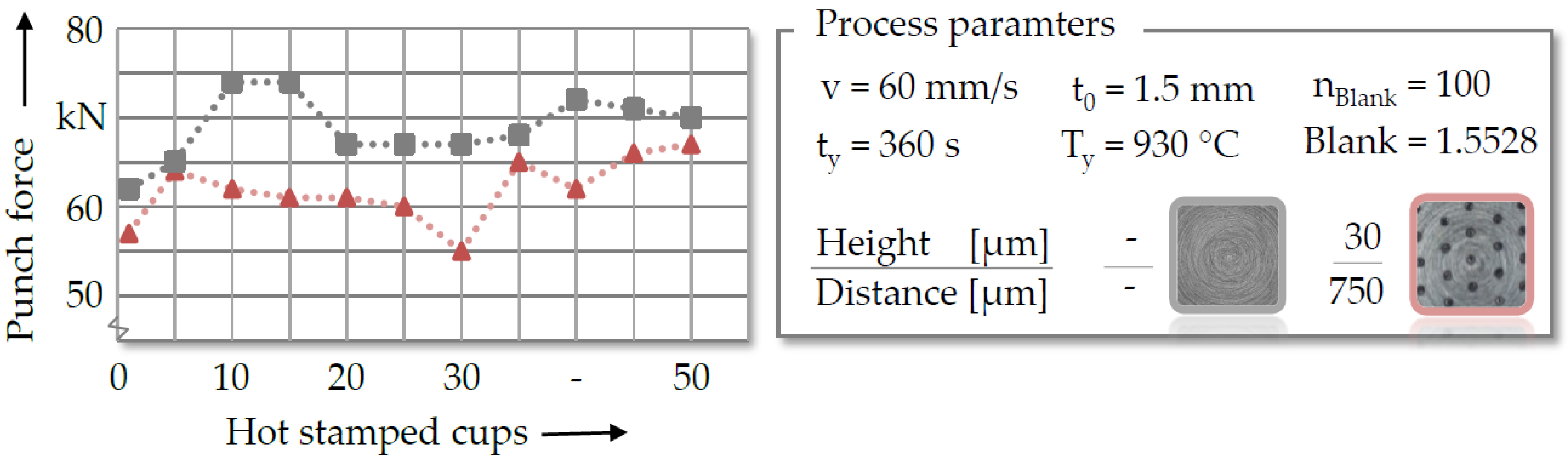
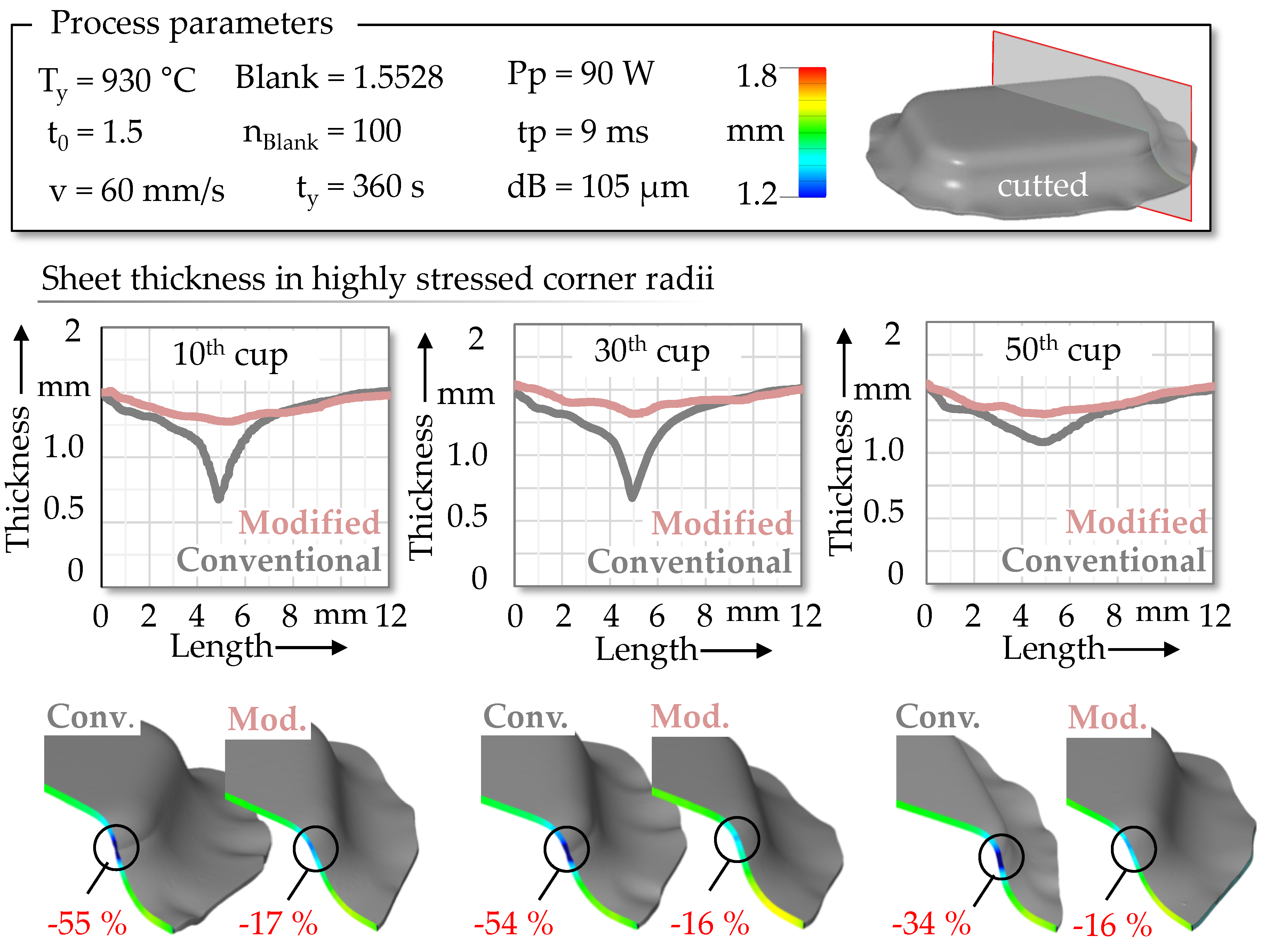
3.4. Hot Stamping of Rectangular Cups

The applicability and transferability of the surface engineering technique concerning an industry-related tool geometry was proven in deep drawing tests. In this context, a laser-implanted tool (hi ~10 µm; ds = 350 µm) as well as a conventional die were used for hot stamping fifty rectangular cups. The maximum punch force was measured by means of an integrated load cell, to evaluate and compare the tribological performance of both tooling systems. The measured force values of every fifth manufactured cup are exemplary as shown in Figure 18.
With increasing number of parts, tendentially rising punch forces were detected for both tool configurations, which can be explained by the constantly growing amount of tool-sided wear. However, by comparing the punch force development, reduced forming forces were constantly measured for the laser-implanted die. The unmodified tool revealed an average punch force of 68 ± 2 kN, whereas a decreasing force value of 64 ± 3 kN was obtained for the laser-implanted tooling system. This effect may be explained by the significant reduction of the contact area, which diminishes the mechanical interlocking of the roughness peaks at the blank–die interface. Moreover, the improved tribological behavior might also be promoted by the high fraction of hard and finely dispersed particles, which abate the formation of adhesive wear. As a result, decreasing frictional shear forces were gained during the relative movement of the punch, which leads to a reduction of the required forming forces. To deepen the knowledge regarding the tribological impact on resulting part quality, several rectangular cups of both tooling systems were digitized by means of the topometric 3D-sensor ATOS (GOM Metrology, Braunschweig, Germany). Based on these measurements, the resulting sheet thickness distribution of the hot stamped components could be analyzed and compared, which is illustrated in Figure 19.
The highest sheet thickness reduction was always detected in the geometrical complex and highly stressed corner radii of the rectangular cups. By using the unmodified die, an average necking of 47.6% was observed within this area. In contrast, the laser-implanted tool solely caused a sheet thickness reduction by 16.4%, which can be attributed to the diminished frictional shear forces. It is also assumed that the modified tool topography slowed down the cooling of the workpiece at the flange area, since the contact area and the heat dissipation at the blank-die interface is significantly limited. Consequently, reduced yield stresses might also be obtained during the forming operation, which in turn improved the flow behavior of the sheet in the highly stressed contact areas. As a result, the laser-implanted tool minimized local necking by 31.2% on average, which in turn prevents premature material failure or crack initiation.

4. Conclusions

Within the scope of this work, a new surface engineering technology named laser implantation process has been investigated, in order to improve the tribological performance of hot stamping tools. For this purpose, different titanium-based hard ceramic particles have been embedded into hot working tool steel surfaces, which were subsequently analyzed with respect to their geometrical shape and mechanical properties. Afterwards, quenching tests as well as tribological experiments were carried out under hot stamping conditions, in order to qualify the thermal and tribological interactions of the elevated surface features at the blank–die interface. The following main conclusions can be drawn from the executed experiments:
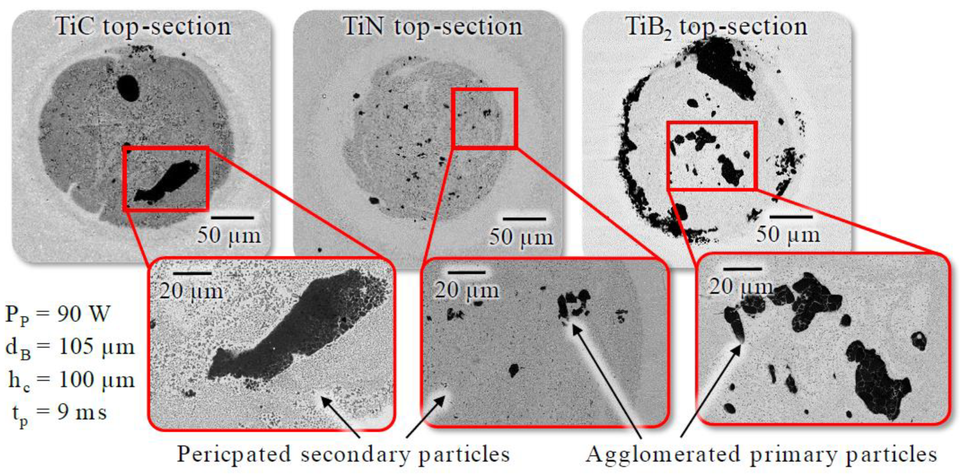
  • The localized dispersing of titanium-based particles (TiC, TiN, and TiB2) by means of pulsed laser radiation enables the generation of a defect-free metal matrix composite with a high share of homogenously disturbed particles. Due to a local volume increase in micrometer range, separated, elevated and highly wear resistant surface features can be created on the hot working tool steel 1.2367. The geometrical shape and mechanical implant properties are controllable by adjusting the laser parameters (pulse power, pulse duration, and m diameter) and the hard phase composition (implantation material and coating height).
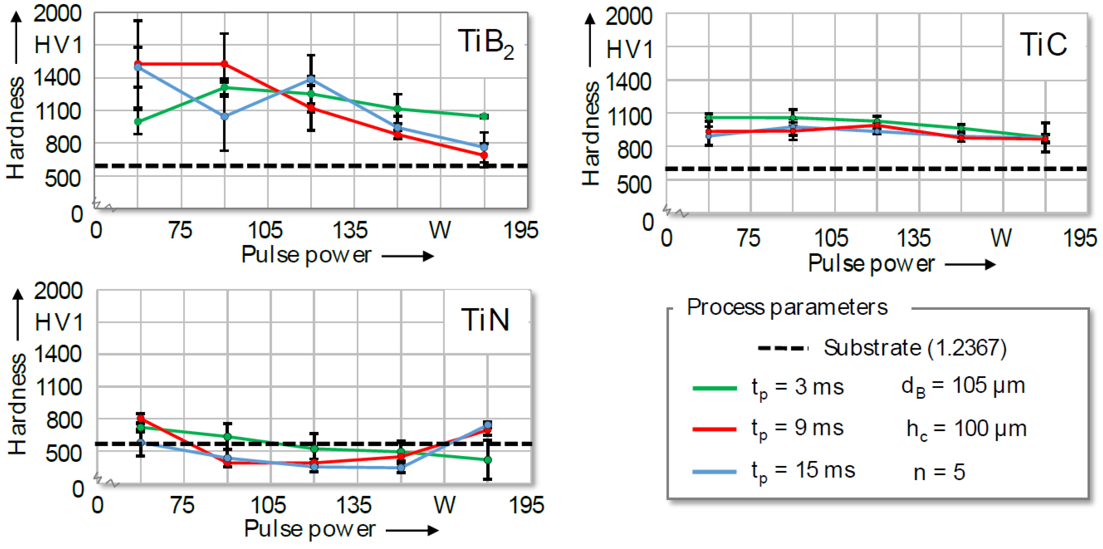
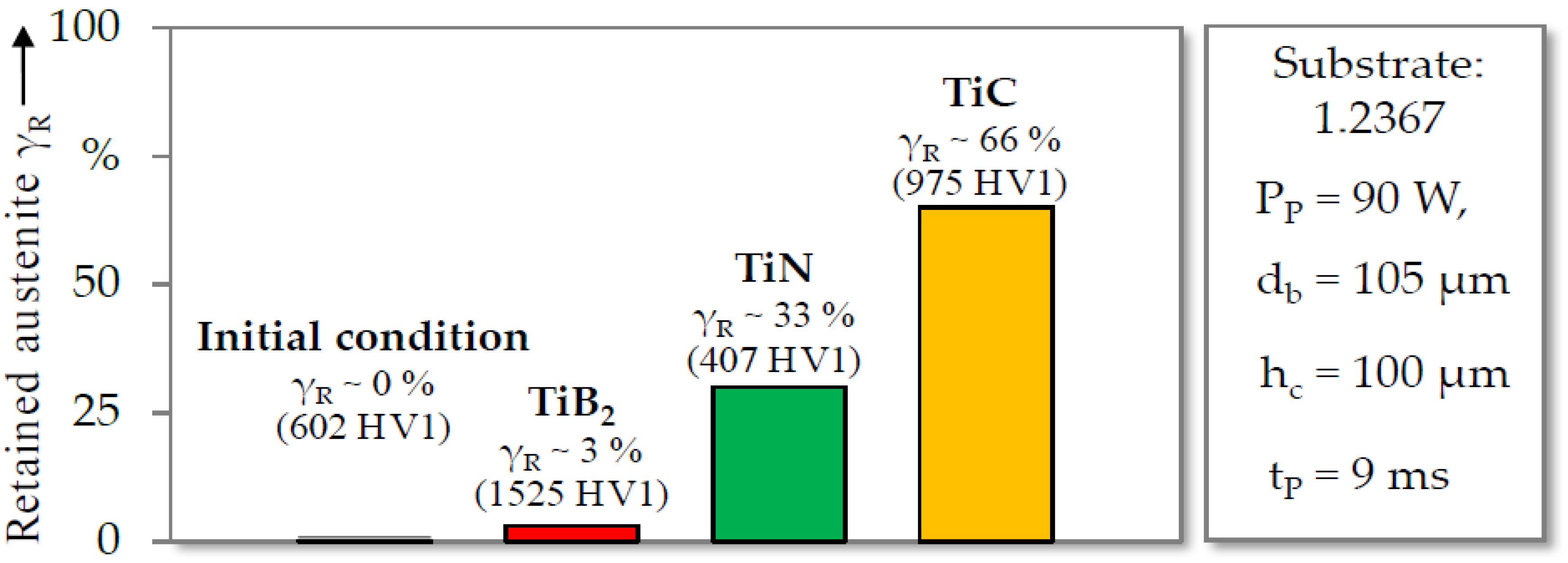
  • By using the same set of laser parameters, different mechanical and geometrical implant properties were achieved for all titanium-based materials. The particle size and material characteristics of the hard ceramic particles are highly influencing the resulting implantation behavior. With decreasing grain size and melting temperature, a higher proportion of ceramic particles will be dissolved in the melt, which in turn results in implants with reduced dome-heights. Moreover, the chemical composition of the hard particles has a significant impact on the resulting share of retained austenite, which directly affects the hardness values of the spots. Titanium diboride (TiB2) seemed to be very suitable to reduce the tribological load within hot stamping, as the implanted spots revealed the highest hardness values up to 1600 HV1. By combining different implantation materials or using other types of particles (e.g., niobium), tailored implant properties may be produced in further studies.
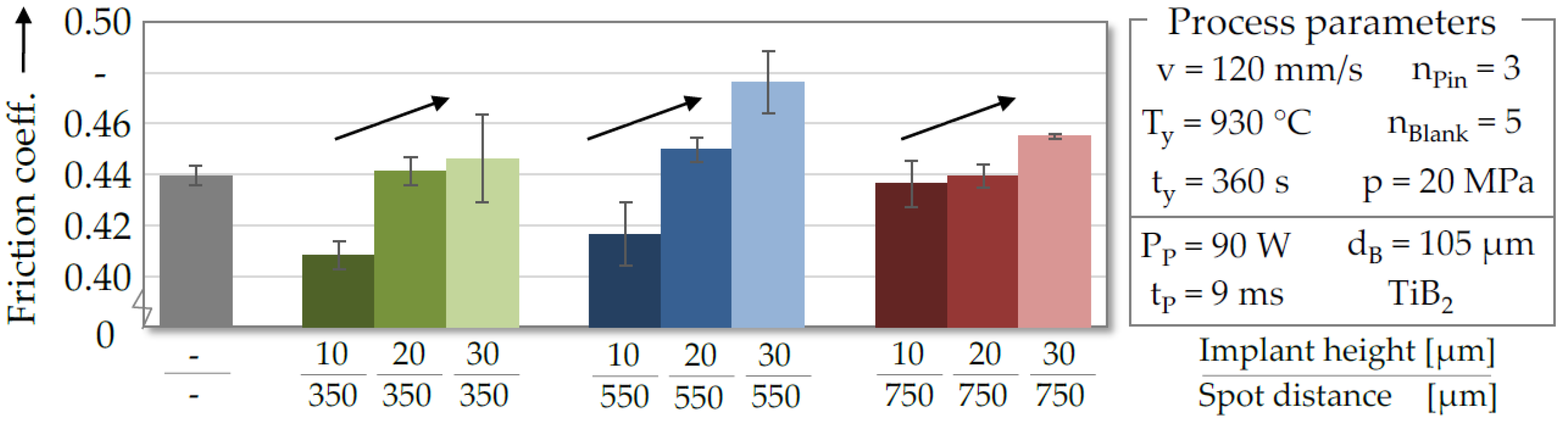
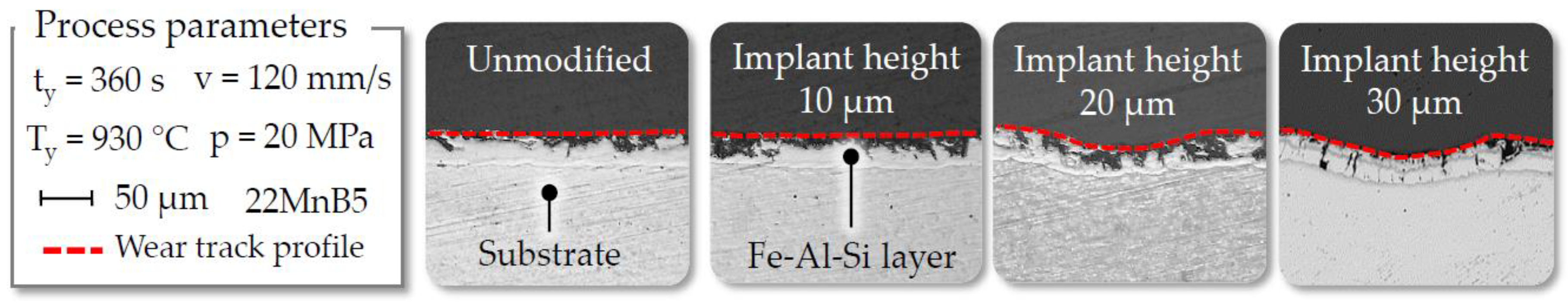
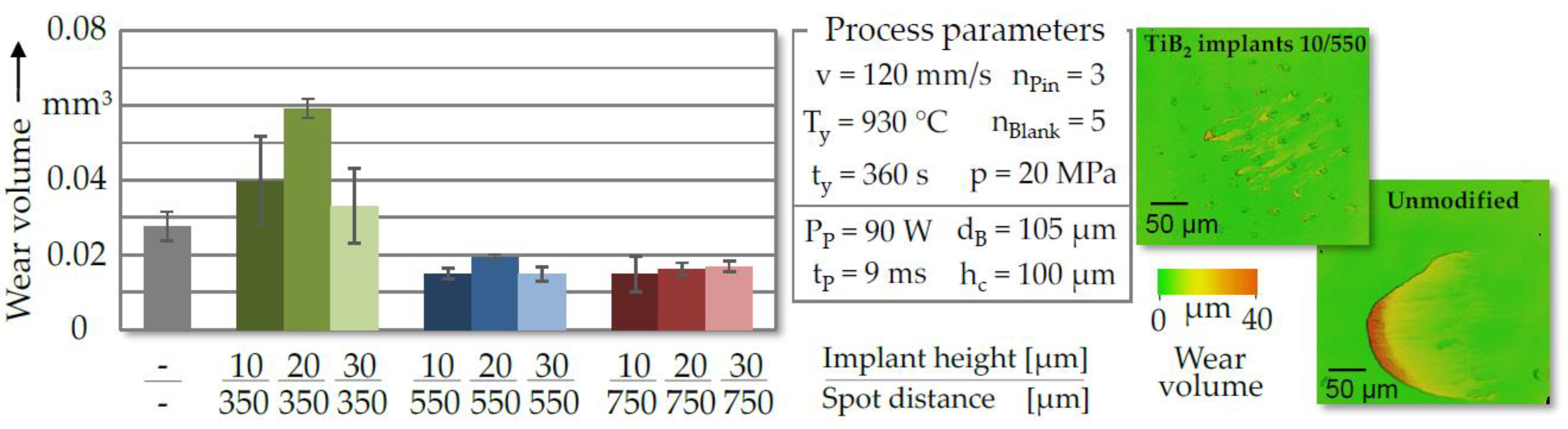
  • Depending on the generated height and distance of the laser-generated TiB2 spots, a significantly higher wear resistance and reduced friction forces were gained in contrast to conventional tool topographies due to the limited contact area and the high share of homogenously disturbed hard ceramic particles. By varying the pattern and geometrical shape of the elevated surface features, a tailored adjustment of the contact behavior and material flow can be pursued to enhance the tribological performance and effectiveness of this surface engineering technique even more.
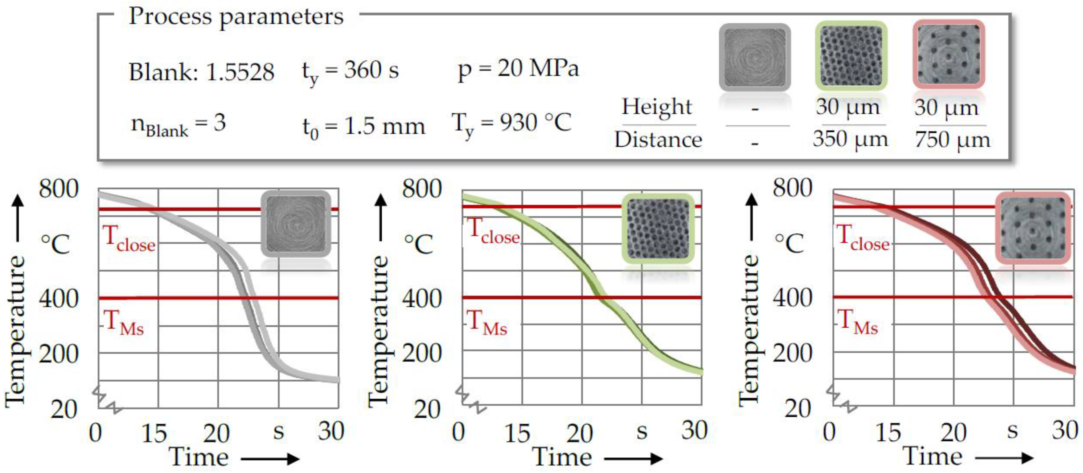
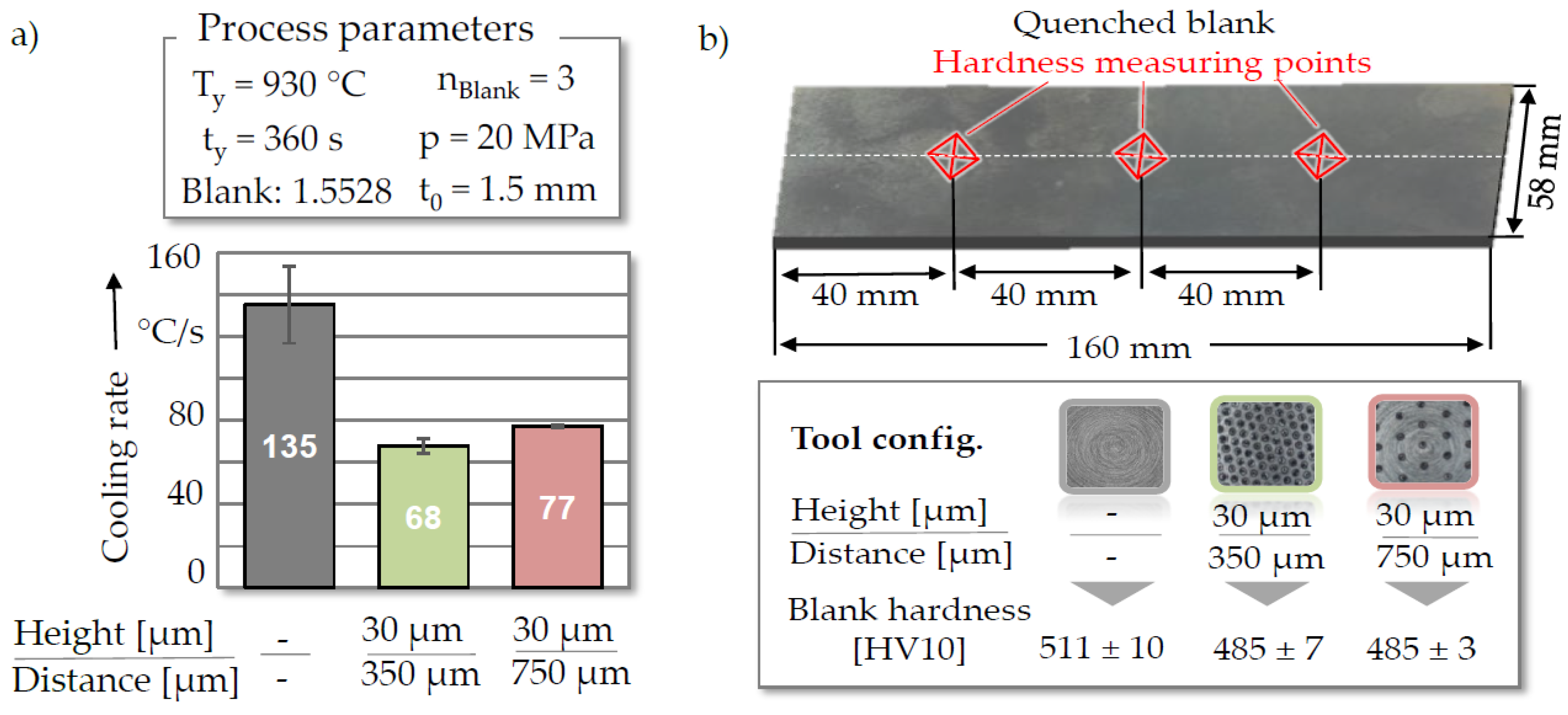
  • The laser implantation technique offers the possibility to control the thermal interactions between tool and workpiece, which directly affects the mechanical properties of the hot stamped parts. Different cooling rates were gained by merely adjusting the distance between the microstructure. In this context, it is expected that varying the height of the elevated features might also affect the thermal behavior, since the gap and heat transmission at the blank-die interface is significantly influenced. This effect could offer great potential for producing tailored mechanical properties, which is highly desired within partial hot stamping. To verify these assumptions, different implant heights and spot distances will be investigated in further studies to adjust the thermo-mechanical properties of rectangular cups. Before and after the forming operation are carried out, measurements of the blank hardness and temperature distribution might be performed, in order to qualify the cause–effect relations.

Author Contributions

Conceptualization, S.S. and F.S.; methodology, S.S. and F.S.; investigation, S.S. and F.S.; writing—original draft preparation, S.S. and F.S.; writing—review and editing, S.S., F.S., K.H. and M.M.; visualization, S.S. and F.S.; supervision, K.H. and M.M. All authors have read and agreed to the published version of the manuscript.

Funding

This work was funded by the German Research Foundation (DFG) within the scope of the project ME 2043/68-1 “Laser implantation of press hardening tools to influence the tribological and thermal properties for the process application”.

Conflicts of Interest

The authors declare no conflict of interest.

References

  1. Mori, K.I.; Bariani, P.F.; Behrens, B.A.; Brosius, A.; Bruschi, S.; Maeno, T.; Merklein, M.; Yanagimoto, J. Hot stamping of ultra-high strength steel parts. CIRP Ann. 2017, 66, 755–777. [Google Scholar] [CrossRef]
  2. Nakagawa, Y.; Mori, K.I.; Yashima, S.; Kaido, T. Springback behaviour and quenchability in hot stamping of thick sheets. Procedia Manuf. 2018, 15, 1071–1078. [Google Scholar] [CrossRef]
  3. Karbasian, H.; Tekkaya, A.E. A review on hot stamping. J. Mater. Process. Technol. 2010, 210, 2103–2118. [Google Scholar] [CrossRef]
  4. Behrens, B.A.; Bouguecha, A.; Gaebel, C.M.; Moritz, J.; Schrödter, J. Hot Stamping of Load Adjusted Structural Parts. Procedia Eng. 2014, 81, 1756–1761. [Google Scholar] [CrossRef] [Green Version]
  5. Bruschi, S.; Ghiotti, A. Hot Stamping. Compr. Mater. Process. 2014, 3, 27–54. [Google Scholar]
  6. Merklein, M.; Lechler, J. Investigation of the thermo-mechanical properties of hot stamping steels. J. Mater. Process. Technol. 2006, 177, 452–455. [Google Scholar] [CrossRef]
  7. Billur, E. Hot Stamping of Ultra High-Strength Steels, 1st ed.; Springer: Cham, Switzerland, 2019. [Google Scholar]
  8. Venema, J.; Botman, G.; Phan, T.; Kop, T. Formability of AlSi and Zn coating during hot stamping. Mater. Sci. Eng. 2019, 651, 120–127. [Google Scholar] [CrossRef]
  9. Ghiotti, A.; Bruschi, S.; Borsetto, F. Tribological characteristics of high strength steel sheets under hot stamping conditions. J. Mater. Process. Technol. 2011, 211, 1694–1700. [Google Scholar] [CrossRef]
  10. Mu, Y.; Simonetto, E.; Scagnolari, M.; Ghiotti, A. Wear in Hot Stamping by Partition Heating. J. Manuf. Mater. Process. 2020, 4, 18. [Google Scholar] [CrossRef] [Green Version]
  11. Vilaseca, M.; Pujante, J.; Ramírez, G.; Casellas, D. Investigation into adhesive wear of PVD coated and uncoated hot stamping production tools. Wear 2013, 308, 148–154. [Google Scholar] [CrossRef]
  12. Pelcastre, L. Hot Forming Tribology, 1st ed.; Luleå Tekniska Universitet: Luleå, Sweden, 2011. [Google Scholar]
  13. Birol, Y.; İsler, D. Response to thermal cycling of CAPVD (Al,Cr)N-coated hot work tool steel. Surf. Coat. Technol. 2010, 205, 275–280. [Google Scholar] [CrossRef]
  14. Shihomatsu, A.; Button, S.T.; Silva, I.B.D. Tribological Behavior of Laser Textured Hot Stamping Dies. Adv. Tribol. 2016, 2016, 1–15. [Google Scholar] [CrossRef]
  15. Mousavi, A.; Sperk, T.; Gietzelt, T.; Kunze, T.; Lasagni, A.F.; Brosius, A. Effect of Contact Area on Friction Force in Sheet Metal Forming Operations. Key Eng. Mater. 2018, 767, 77–84. [Google Scholar] [CrossRef]
  16. Spranger, F.; Oliveira Lopes, M.D.; Schirdewahn, S.; Degner, J.; Merklein, M.; Hilgenberg, K. Microstructural evolution and geometrical properties of TiB2 metal matrix composite protrusions on hot work tool steel surfaces manufactured by laser implantation. Int. J. Adv. Manuf. Technol. 2020, 106, 481–501. [Google Scholar] [CrossRef]
  17. Hilgenberg, K.; Steinhoff, K. Texturing of skin-pass rolls by pulsed laser dispersing. J. Mater. Process. Technol. 2015, 225, 84–92. [Google Scholar] [CrossRef]
  18. Merklein, M.; Lechler, J. Determination of Material and Process Characteristics for Hot Stamping Processes of Quenchenable Ultra High Strength Steels with Respect to a FE-based Process Design. Int. J. Mater. Manf. 2009, 1, 411–426. [Google Scholar] [CrossRef]
  19. Spranger, F.; Hilgenberg, K. Dispersion behavior of TiB2 particles in AISI D2 tool steel surfaces during pulsed laser dispersing and their influence on material properties. Appl. Surf. Sci. 2019, 467, 493–504. [Google Scholar] [CrossRef]
  20. Hilgenberg, K.; Behler, K.; Steinhoff, K. Localized dispersing of ceramic particles in tool steel surfaces by pulsed laser radiation. Appl. Surf. Sci. 2014, 305, 575–580. [Google Scholar] [CrossRef]
  21. Spranger, F.; Schirdewahn, S.; Kromm, A.; Merklein, M.; Hilgenberg, K. On the influence of TiB2, TiC, and TiN hard particles on the microstructure of localized laser dispersed AISI D2 tool steel surfaces. J. Laser Appl. 2020, 32, 22028. [Google Scholar] [CrossRef]
  22. Wang, K.; Gui, Z.; Liu, P.; Wang, Y.; Zhang, Y. Cracking Behavior of Al-Si Coating on Hot Stamping Boron Steel Sheet. Procedia Eng. 2014, 81, 1713–1718. [Google Scholar] [CrossRef]
  23. Venema, J.; Hazrati, J.; Matthews, D.; van den Boogaard, T. An Insight in Friction and Wear Mechanisms during Hot Stamping. Key Eng. Mater. 2018, 767, 131–138. [Google Scholar] [CrossRef]
  24. Klocke, F. Manufacturing Processes, 1st ed.; Springer: Berlin, Germany, 2009. [Google Scholar]
  25. Schwingenschlögl, P.; Niederhofer, P.; Merklein, M. Investigation on basic friction and wear mechanisms within hot stamping considering the influence of tool steel and hardness. Wear 2019, 426, 378–389. [Google Scholar] [CrossRef]
  26. He, L.F.; Zhao, G.Q.; Li, H.P. Measurement and Analysis of Time-Temperature-Transformation Curves of Boron Steel 22MnB5. Appl. Mech. Mater. 2010, 29, 484–489. [Google Scholar] [CrossRef]
  27. Kong, L.; Peng, Y. In situ observation on microstructure evolution of 22MnB5 in hot stamping process. Meter. Res. Technol. 2019, 116, 209. [Google Scholar] [CrossRef]
  28. Zhou, J.; Wang, B.Y.; Huang, M.D.; Cui, D. Effect of hot stamping parameters on the mechanical properties and microstructure of cold-rolled 22MnB5 steel strips. Int. J. Miner. Metall. Mater. 2014, 21, 544–555. [Google Scholar] [CrossRef]
Figure 1. Schematic representation of the laser implantation process according to [16].
Jmmp 04 00068 g001
Figure 2. Testing apparatus and experimental procedure for quantifying the wear and friction behavior of unmodified and laser-implanted tool surfaces.
Jmmp 04 00068 g002
Figure 3. Tool configurations and worn blank topography.
Jmmp 04 00068 g003
Figure 4. Process principle for analyzing the occurring amount of tool-sided wear.
Jmmp 04 00068 g004
Figure 5. Tooling setup and modified contact plate for analyzing the cooling behavior.
Jmmp 04 00068 g005
Figure 6. Laser-implanted tooling system for hot stamping rectangular cups.
Jmmp 04 00068 g006
Figure 7. Laser-generated surface features classified according to their visual appearance.
Jmmp 04 00068 g007
Figure 8. Top view of section II classified microfeatures along with a cross-section image, which illustrates the melt convection developed in the implantation process.
Jmmp 04 00068 g008
Figure 9. Measured hardness values in dependence on the applied pulse power and pulse duration.
Jmmp 04 00068 g009
Figure 10. Backscattered electron microscopy (SEM-BSE) image of the precipitated top-section and corresponding detail view.
Jmmp 04 00068 g010
Figure 11. Retained austenite content for different material conditions.
Jmmp 04 00068 g011
Figure 12. Quantified friction coefficients by using unmodified and laser-implanted tools.
Jmmp 04 00068 g012
Figure 13. Tactile measurements of the worn blank topography according to the German Industrial Standard DIN 4476.
Jmmp 04 00068 g013
Figure 14. Cross-sectional preparations of the wear tracks.
Jmmp 04 00068 g014
Figure 15. Quantified surface wear by using unmodified and laser-implanted tooling systems.
Jmmp 04 00068 g015
Figure 16. Recorded temperature profiles of the quenched blanks.
Jmmp 04 00068 g016
Figure 17. (a) Calculated cooling rates and (b) corresponding hardness of the quenched blanks.
Jmmp 04 00068 g017
Figure 18. Maximum punch force value of every fifth manufactured cup by using a locally modified as well as a conventional die.
Jmmp 04 00068 g018
Figure 19. Resulting sheet thickness thinning of the hot stamped rectangular cups.
Jmmp 04 00068 g019
Table 1. Material properties of the hot working tool steel X38CrMoV5-3 (1.2367).
Chemical Composition of the Hot Working Tool Steel X38CrMoV5-3 in wt.%
CSiMnPSCrMoVFe
Measured0.330.340.330.0130.0054.842.960.53bal.
Nominal0.35–0.400.30–0.500.30–0.50≤0.03≤0.024.80–5.202.70–3.200.40–0.60bal.
Optical MicrographXRD-Diffractogram of Retained Austenite
Jmmp 04 00068 i001 Jmmp 04 00068 i002
Mechanical Properties
Density7.83 g/cm3Hardness~602 HV1Thermal conductivity35 W/mK
Table 2. Mechanical properties of the applied hard ceramic particles.
Mechanical PropertiesTiB2TiCTiN
MicrostructureHexagonalCubicCubic
Melting point [°C]322530672950
Density [g/cm3]4.504.935.21
Hardness [HV1]348032002450
Thermal expansion [10−6 K−1]6.67.69.4
Grain size [d50]5.32.83.2
Visualization of particle shape via SEM-analysis Jmmp 04 00068 i003 Jmmp 04 00068 i004 Jmmp 04 00068 i005

