Communication

Hot Gas Forming of Aluminum Alloy Tubes Using Flame Heating

1
Department of Mechanical Engineering, Materials Science, and Ocean Engineering, Graduate School of Engineering Science, Yokohama National University, Yokohama, Kanagawa 240-8501, Japan
2
College of Engineering, Design and Physical Sciences, Brunel University London, Uxbridge, Middlesex UB8 3PH, UK
3
Department of Mechanical Engineering, Khomeinishahr Branch, Islamic Azad University, Khomeinishahr, Isfahan 81857-93768, Iran
4
Division of Systems Research, Faculty of Engineering, Yokohama National University, Yokohama, Kanagawa 240-8501, Japan
*
Author to whom correspondence should be addressed.
J. Manuf. Mater. Process. 2020, 4(2), 56; https://doi.org/10.3390/jmmp4020056
Submission received: 23 May 2020 / Revised: 10 June 2020 / Accepted: 13 June 2020 / Published: 16 June 2020

Abstract

:
Hot metal gas forming (HMGF) is a desirable way for the automotive industry to produce complex metallic parts with poor formability, such as aluminum alloys. A simple hot gas forming method was developed to form aluminum alloy tubes using flame heating. An aluminum alloy tube was heated by a flame torch while the tube was rotated and compressed using a lathe machine and simultaneously pressurized with a constant air pressure. The effects of the internal pressure and axial feeding on expansion and wall thickness distribution were examined. The results showed that the proposed gas forming method was effective for forming aluminum alloy tubes. It was also indicated that axial feeding is a vital parameter to prevent reductions in wall thickness by supplying the material flow during the forming process.

1. Introduction

In recent years, light-weight materials such as aluminum alloys have been widely used in the automotive and aerospace industries. Tube hydroforming is a well-known forming process that is utilized to form tubular components with variable cross-sections using internal pressure media. However, it is difficult to gain a proper pressure path in hydroforming, and forming defects such as rupture or folding can occur.
The poor formability of low ductility materials such as aluminum alloys at room temperature limits their applications. Therefore, warm and hot forming processes have been proposed to increase the formability of materials with low ductility at room temperature. Alzahrani et al. [1] analytically modeled a multi-nose symmetric tube in the hydroforming process based on a mechanistic approach. Afshar et al. [2] investigated the forming limit diagrams of hydroformed aluminum tubes to predict bursting, and they compared the numerical results with experimental tests. Keigler et al. [3] enhanced the formability of aluminum components via warm hydroforming, and they studied the effect of temperature controlling on wall thickness and microstructure before and after the forming process. Yi et al. [4] introduced a new combined heating system for the warm hydroforming of light-weight alloy tubes. Hwang et al. [5] examined the T-shape hydroforming of an AZ61 magnesium alloy at 150 and 300 °C. Chan and Kot [6] studied the formability of an AZ31B magnesium alloy made by three different loading paths for quadrilateral tubular components fabricated by the warm tube hydroforming process. However, warm tube hydroforming has a limitation on the heating temperature: it is generally kept below 300 °C to prevent the evaporation of fluid media such as oil and water.
The limitation of the heating temperature in the tube forming can be eliminated by utilizing gas as a pressure medium. The hot metal gas forming (HMGF) of tubes is a novel hot-forming process that is utilized to form hollow steel and aluminum alloy parts. In this process, a tube is formed into a specific shape by gas or air pressure while the tube is heated before or during the forming process. Dykstra et al. [7] proposed the hot gas forming process to form hot metallic tubes. However, it is difficult to simultaneously control the heating temperature and internal pressure during gas forming due to the short deformation time of tubes in gas forming. Since internal gas pressure is compressive and the volume of the pressure medium is automatically expanding, it is difficult to control the deformation behavior. Most often, electrical resistance or electromagnetic induction methods are used to heat tubes [8,9,10,11,12]. However, Joule heating requires a certain electrical resistance for heating materials, and it is not suitable for heating an aluminum alloy with a high electric conductivity. Therefore, other heating methods such as flame heating can be effective for the heating of aluminum alloy tubes.
Vadillo et al. [13] compared their simulation and experimental results of the hot gas forming technology for high-strength steel and stainless-steel tubes. Maeno et al. [14] developed a hot gas bulging process for an aluminum alloy tube using resistance heating. Maeno et al. [15] optimized the forming condition in the hot tube gas bulging of aluminum alloys using resistance heating set into dies. He et al. [16] investigated the mechanical properties and formability of TA2 extruded tubes in HMGF at elevated temperatures. Maeno et al. [17] formed an ultra-high-strength steel hollow part by stamping an air-filled steel tube using resistance heating. Liu et al. [18] determined the formability of titanium tubular components for high-pressure gas forming at elevated temperatures. Paul and Strano [19] studied the influence of the process variables on the gas forming and press hardening of steel tubes. They also determined the effects of internal pressure and preheating on hardening and the surface finish. Talebi Anaraki et al. [20] developed the gas forming of tubes using pulsating pressure and oscillating heating. Their results revealed that, upon applying pulsating pressure, the wall thickness gradually decreased. The oscillated heating, accompanied by pulsating pressure, increased the bulging area. Though large deformation zone is suitable for forming with dies, it is difficult to use forming dies with flame heating. The flame heating technique is suitable for the dieless forming of tubes.
In hot tube forming using local heating, dieless forming has been studied. Hwang et al. [21] developed the dieless drawing of stainless steel for tube- or wire-drawing processes using a high-frequency heating source. Furushima and Manabe [22] reported the effectiveness of the dieless drawing process for microtube fabrication. The dieless gas forming of tubes is an advanced material-forming technology that can be classified as a flexible forming process with the absence of die materials. Dieless gas forming can be utilized to manufacture automobile parts, pressure vessel heads, large elbow joints, etc.
In this paper, to utilize flame heating for dieless gas forming, local deformation behavior was investigated. The gas forming of an aluminum alloy tube using fixed flame heating was performed. The effects of the internal pressure and axial feeding on the expansion and wall thickness distribution of the deformed tubes were evaluated in experiments. In addition, the effect of the gas forming process on the microstructure was studied.

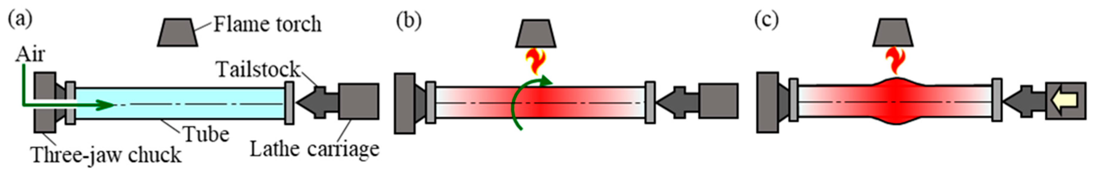
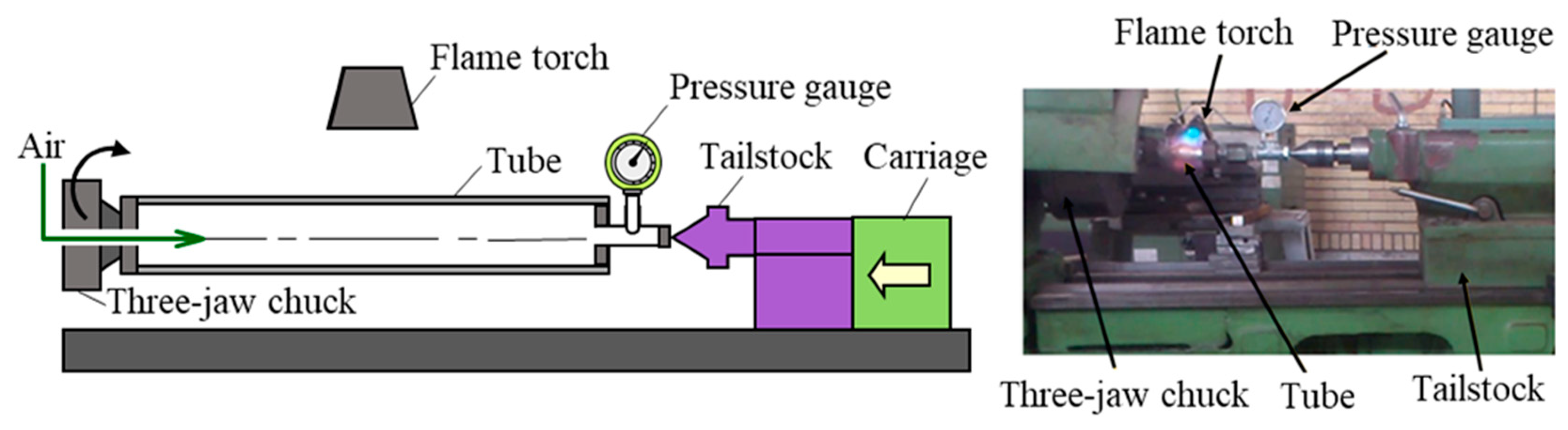
2. Hot Gas Forming of Aluminum Alloy Tubes Using Flame Heating

Experimental Procedure

To investigate the bulging behavior in the local area, a hot gas forming apparatus was utilized to simplify the equipment for the experimental approach and the heating of tubes using flame heating. It is difficult to control the generation of heat using resistance heating because it is dependent on thickness. The heat generated in this case was concentrated on the heating portion due to the high current density. However, by using flame heating, the heating portion can be controlled, which makes it suitable for the heating of aluminum alloys with a low resistivity. The sequence of the hot gas forming of a tube using a lathe machine by flame heating and a schematic drawing of the tube and air sealing components are shown in Figure 1 and Figure 2, respectively. Conical bushes and brass housings were used to seal the tube. The tube was filled with compressed air and provided with a flow control valve and an air compressor. The air that filled the tube was heated with a fixed flame torch placed a specific distance away during the experiments. To increase the uniformity of the temperature distribution of the tube during the forming process, the tube was rotated by employing a three-jaw chuck of the lathe machine.
The tailstock of the lathe machine provided the required axial feeding to decrease the thinning of the tube. Due to the forming conditions in the present forming method, the lathe machine’s tailstock pushed the tube during the experiments and fed the tube. The tailstock was pushed and controlled by the automation feeding of the lathe carriage to simplify the forming setup. This simple mechanism eliminated the extra components to form a rotating tube using a lathe machine with the proposed heating mechanism. The experimental apparatus of the hot gas forming of an aluminum alloy tube using flame heating is shown in Figure 3. An aluminum 6063-T5 tube that was 25 mm in outer diameter and 1.5 mm in wall thickness was utilized in the experiment. The chemical compositions of the aluminum alloy are presented in Table 1. The velocity of the pushing of the tailstock was constant at 0.07 mm/rev, and the tube (130 mm in length) was rotated with a constant rotational velocity of 22.4 RPM by the lathe machine. The dimensions and conditions of the hot gas forming of the tubes are shown in Table 2.
Internal pressure and axial feeding (stroke) are the most critical parameters in the gas forming process. The internal pressure (p), which was measured by the pressure gauge at the plug, was kept constant during the experiment. The stroke of the axial feeding (s) term was defined as the axial compression in the axial direction of the tube. According to the designed equipment, the stroke was defined as the total amount of moving of the tailstock, which was equal to the difference in the tube length before and after forming.
The bulging was the difference between the tube’s diameter before and after deformation. In this study, the tube freely bulged until bursting occurred to achieve the maximum diameter. It should be noted that the desired final geometry in dieless gas forming can be tuned by controlling the heating position or using contact tools.
The internal pressure (p) and the total amount of stroke (s) were varied in the experiment, as shown in Table 3. The free bulging (i.e., forming without dies) was carried out using three different values of constant internal pressure. The tubes were subjected to pressures of 0.4, 0.55, and 0.7 MPa to investigate the effect of internal pressure on the expansion and thickness distribution of the deformed parts. Then, the tubes were bulged by a maximum internal pressure of 0.7 MPa with and without axial feeding to investigate the effect of the axial feeding during the forming process of the tubes at a constant air pressure. In addition, due to the instability of the fracture phenomenon, all of the experiments were done three times until the coefficient of variation of the bulging diameter results was less than 3%, and then the average values were calculated.
The temperature distribution along the heated tube was measured by an infrared thermometer, as shown in Figure 4. The emissivity is calculated by a thermocouple. The tube was heated for 90 s before bulging to increase the temperature and to achieve a steady-state condition. The temperature distribution was measured by the moving sensor. The scanning time of the temperature distribution was about 6 s along the tube. It should be noted that the surface between the tube and the sealing components was assumed to be at a constant temperature (about 200 °C). The temperature distribution of the tube was not constant on the surface of the tube, which indicated that the temperature was varied along the tube. The varied temperature distribution is a positive factor in dieless forming to control the heating portion during and after the bulging of aluminum alloys. The temperature of the middle of the tube, which was heated directly by the fixed flame, was higher than in the other sections. Propane gas was used as the fuel of the flame heating, and the flame was set within 200 mm of the center of the tube. The temperature profile was constant during the experiments, and the temperature of the extruded tube in the middle section was about 560 °C.

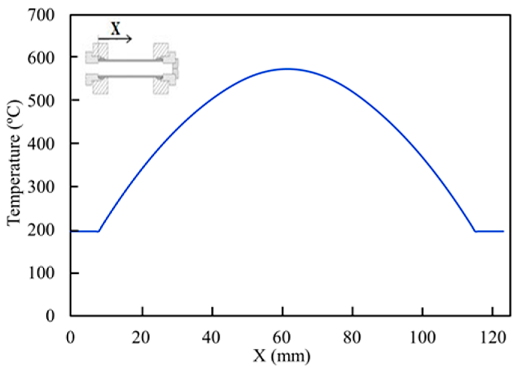
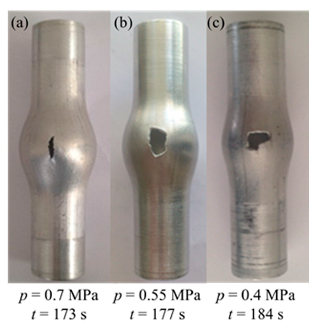
3. Results of Bulging Behavior

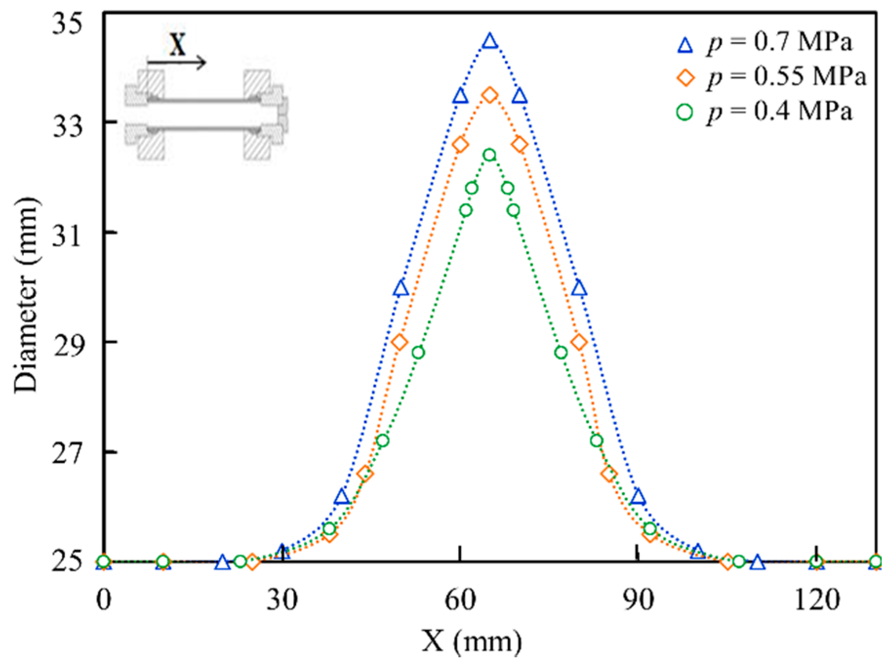
3.1. Effect of Internal Pressure on Bulging Behavior

The tubes formed by three different constant pressures with a stroke of 5 mm and the duration times are shown in Figure 5. The deformed tubes with lower pressures (p = 0.55 MPa and p = 0.4 MPa with s = 5 mm) were melted without sufficient bulging due to the longer forming process time, whereas for the pressure of p = 0.7 MPa with s = 5 mm, bursting occurred due to greater tensile stress in the hoop and axial directions; thus, the tube was bulged before melting after a lower heating time. Figure 6 shows the expansion of the deformed tubes for three applied internal pressures. It can be concluded that, as the pressure increased, the expansion of the bulged tube increased.
The bulged specimen was cut in the hoop direction by means of a wire cutting machine, and the amounts of the wall thickness were measured by an accurate micrometer. The wall thickness distribution at the center of protrusion of the bulged tube, which was formed by the pressure of 0.7 MPa and the stroke of 5 mm, is shown in Figure 7. The wall thickness reduction was measured in the hoop direction, and the results showed that the thickness decreased near the bursting portion of the bulged tube.

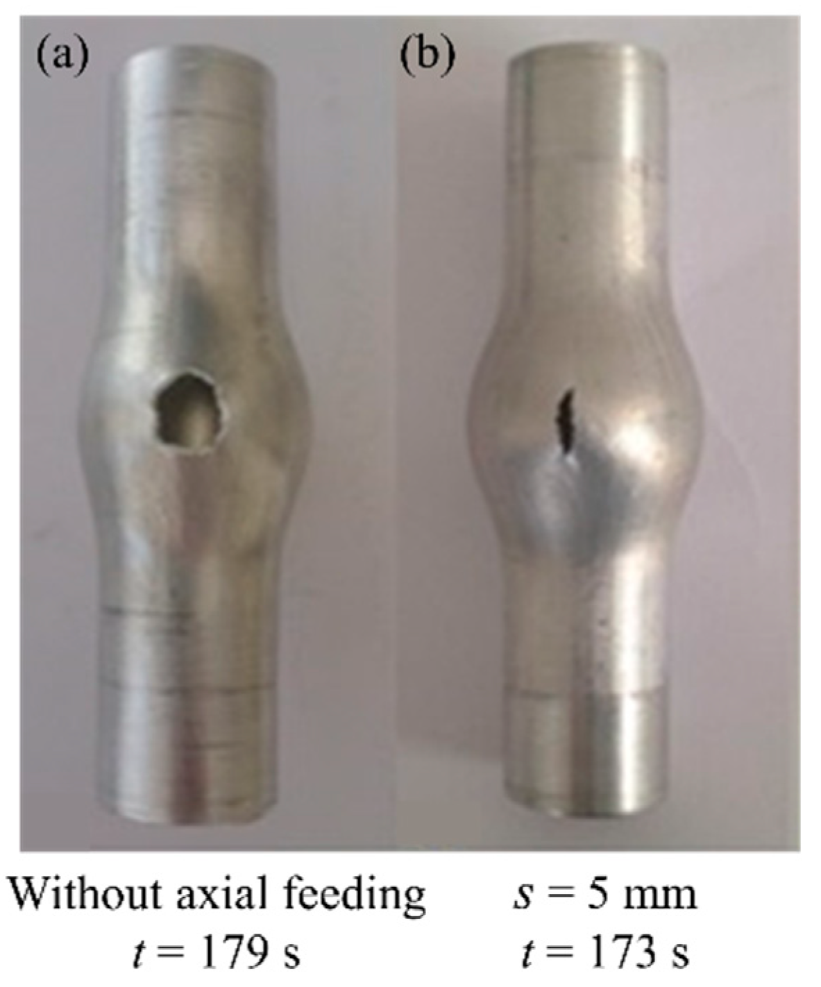
3.2. Influence of Axial Feeding on Expansion

The effect of axial feeding on deformed parts for p = 0.7 MPa is shown in Figure 8. This figure shows that, after eliminating the axial feeding, the forming time increased and the bulging area was melted. Therefore, bursting occurred and the amount of bulge height was significantly smaller than that of the other tube. Figure 9 compares the cross-sectional shape of the tubes with and without axial feeding; the results showed that the axial feeding increased the expansion of the bulged tube by providing better material flow during the forming process, and it postponed bursting by supplying material in the deformation area. The results also indicated that, as the amount of the axial feeding increased, the expansion of the bulged tube also increased.

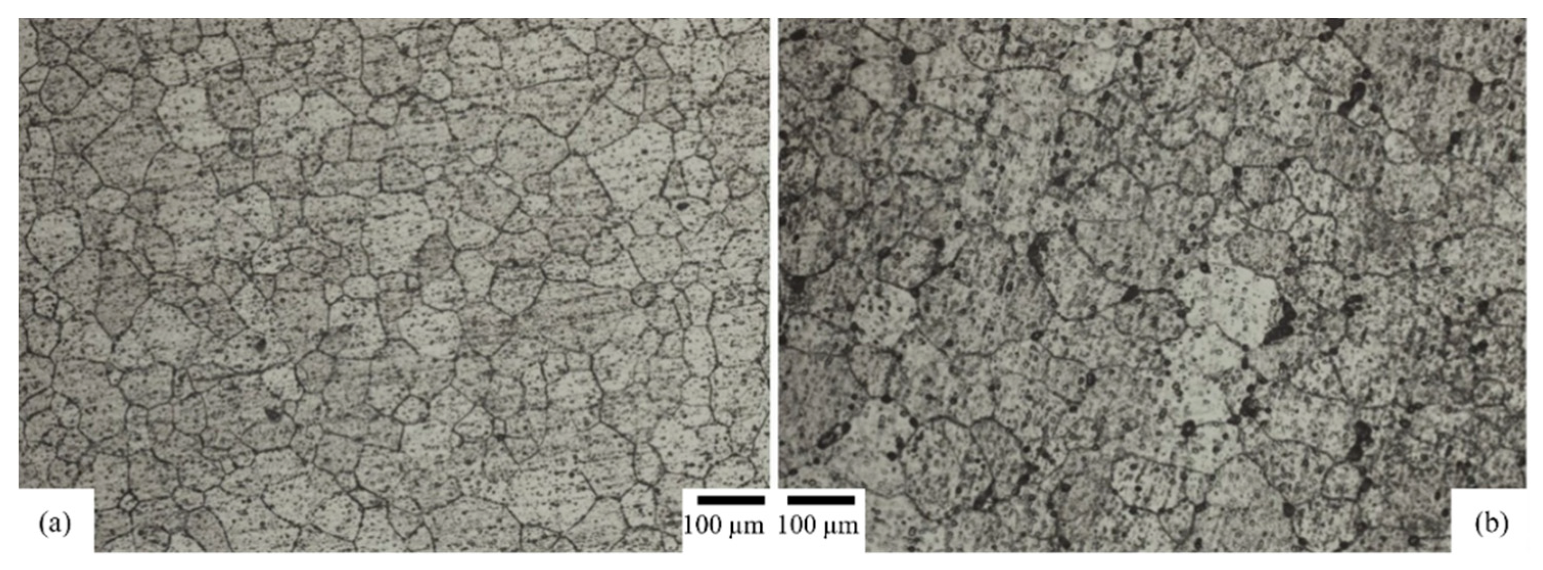
3.3. Effect of Gas Forming on Microstructure

Samples from the fractured part of the deformed tube were taken, and the average grain size of the sample was compared with the undeformed tube. The samples were prepared by polishing with abrasive silicone paper and etched by Keller’s etch solution for 10 s. The grain morphologies before and after the forming process for the center of the bulged tube are compared in Figure 10. This figure shows that grain growth appeared after the forming process. The average grain size of the sample after the bulging process increased by almost 73%, from 55.36 to 95.88 µm. It can be seen that increasing the temperature obviously stretched the grains in the deformation direction. The deformation process also made the grain structures amorphous, a phenomenon caused by large amounts of elongation at high temperatures. The other reason that the grain size was larger was that there was a reduction in the cooling time due to the open die characteristic of the free bulge forming operation. This means that the tube was quenched by the air and the grain size was larger. These results agree well with those obtained by He et al. [23], who showed the effect of hot gas forming on AA6061 microstructures before and after the gas forming process at different temperatures. Both sets of results showed that the grains were stretched at a higher temperature along the deformation direction.

4. Conclusions

In this paper, the hot metal gas forming of aluminum tubes at an elevated temperature was investigated, and the following conclusions were drawn:
  • The flame heating of the rotating tube using the lathe machine was effective at simplifying the heating process during the hot gas forming of aluminum alloys.
  • A high constant pressure increased the expansion until bursting; low pressure led to an increase in the forming time and melted the sample without sufficient bulging.
  • The maximum expansion occurred in the flame focusing zone due to the elevated temperature distribution along the heated tube.
  • The experimental results showed that the axial feeding increased the bulge height and improved the formability of the tubes.
To reduce the weight of automobile parts, demand is increasing for hollow aluminum alloy products. It is difficult to form aluminum alloy tubes with a low ductility by conventional tube forming processes. The present process developed using flame heating is one of the simplest for producing hollow aluminum alloy parts. Flame heating can control the heating region, i.e., the bulging area can be controlled. Thus, gas bulging using flame heating has the possibility of dieless forming. Therefore, the potential of the present process is large; however, the development of the dieless forming technology by controlling the heating position and condition should be still studied.

Author Contributions

Investigation, A.T.-A. and M.C.; writing—original draft preparation, A.T.-A.; supervision, M.L.-M. and T.M.; writing—review and editing, M.L.-M. and T.M. All authors have read and agreed to the published version of the manuscript.

Funding

This research received no external funding.

Conflicts of Interest

The authors declare no conflict of interests.

References

  1. Alzahrani, B.; Ngaile, G.; Yang, C. Analytical modeling of symmetric multi-nose tube hydroforming. J. Manuf. Process. 2013, 15, 273–286. [Google Scholar] [CrossRef]
  2. Afshar, A.; Hashemi, R.; Madoliat, R.; Rahmatabadi, D.; Hadiyan, B.J.M. Numerical and experimental study of bursting prediction in tube hydroforming of Al 7020-T6. Mech. Ind. 2017, 18, 411. [Google Scholar] [CrossRef]
  3. Keigler, M.; Bauer, H.; Harrison, D.; De Silva, A.K.M. Enhancing the formability of aluminum components via temperature controlled Hydroforming. J. Mater. Process. Technol. 2005, 167, 363–370. [Google Scholar] [CrossRef]
  4. Yi, H.K.; Pavlina, E.J.; VanTyne, C.J.; Moon, Y.H. Application of a combined heating system for the warm hydroforming of lightweight alloy tubes. J. Mater. Process. Technol. 2008, 203, 532–536. [Google Scholar] [CrossRef]
  5. Hwang, Y.M.; Su, Y.H.; Cen, B.J. Tube hydroforming of magnesium alloys at elevated temperatures. ASME J. Eng. Mater. Technol. 2010, 132, 31012. [Google Scholar] [CrossRef]
  6. Chan, L.C.; Kot, W.K.R. Determination of Loading Paths in Warm Hydroforming Reinforced Quadrilateral Tubular Components. Mater. Manuf. Process. 2013, 29, 32–36. [Google Scholar] [CrossRef]
  7. Dykstra, B.; Pfaffmann, G.D.; Wu, X. Hot Metal Gas Forming-the Next Generation Process for Manufacturing Vehicle Structure Components; SAE Technical Paper; SAE: Warrendale, PA, USA, 1999. [Google Scholar]
  8. Jirang, C.; Hans, J.R. Recycling of automotive aluminum. Trans. Nonferrous Met. Soc. China 2010, 20, 2057–2063. [Google Scholar]
  9. Yuan, S.J.; Qi, J.; He, Z.B. An experimental investigation into the formability of hydroforming 5A02 Al-tubes at elevated temperature. J. Mater. Process. Technol. 2006, 177, 680–683. [Google Scholar] [CrossRef]
  10. Kleiner, M.; Geiger, M.; Klaus, A. Manufacturing of lightweight components by metal forming. CIRP Ann. Manuf. Technol. 2003, 52, 521–542. [Google Scholar] [CrossRef]
  11. Novtny, S.; Geiger, M. Process design for hydroforming of lightweight metal sheets at elevated temperatures. J. Mater. Process. Technol. 2003, 138, 594–599. [Google Scholar] [CrossRef]
  12. Hariharan, K.; Balachandran, G.; Sathya Prasad, M. Application of Cost-Effective Stainless Steel for Automotive Components. Mater. Manuf. Process. 2009, 24, 1442–1452. [Google Scholar] [CrossRef]
  13. Vadillo, L.; Santos, M.T.; Gutierrez, M.A.; Perez, I.; Gonzalez, B.; Uthiesangsuk, V. Simulation and Experimental results of the Hot metal gas forming Technology for high strength steel and stainless steel tubes forming. AIP Conf. Proc. 2007, 908, 1199–1204. [Google Scholar]
  14. Maeno, T.; Mori, K.; Fujimoto, K. Development of the Hot Gas Bulging Process for Aluminum Alloy Tube Using Resistance Heating. Key Eng. Mater. 2009, 410, 315–323. [Google Scholar] [CrossRef]
  15. Maeno, T.; Mori, K.; Unou, C. Optimization of condition in Hot Gas Bulging of Aluminum Alloy tube using Resistance Heating set into dies. Key Eng. Mater. 2011, 473, 60–74. [Google Scholar] [CrossRef]
  16. He, Z.B.; Teng, B.G.; Che, C.Y.; Wang, Z.B.; Zheng, K.L.; Yuan, S.J. Mechanical properties and formability of TA2 extrude tube for hot metal gas forming at elevated temperature. Trans. Nonferrous Met. Soc. China 2012, 22, s479–s484. [Google Scholar] [CrossRef]
  17. Maeno, T.; Mori, K.; Adachi, K. Gas forming of ultra-high strength steel hollow part using air filled into sealed tube and resistance heating. J. Mater. Process. Technol. 2014, 214, 97–105. [Google Scholar] [CrossRef]
  18. Liu, G.; Wua, Y.; Zhaoa, J.; Wanga, K.; Yuana, S. Formability determination of titanium alloy tube for high pressure pneumatic forming at elevated temperature. Procedia Eng. 2014, 81, 2243–2248. [Google Scholar] [CrossRef] [Green Version]
  19. Paul, A.; Strano, M. The Influence of Process Variables on the Gas Forming and press Hardening of Steel Tubes. J. Mater. Process. Technol. 2015, 228, 160–169. [Google Scholar] [CrossRef]
  20. Talebi Anaraki, A.; Loh-Mousavi, M.; Wang, L.-L. Experimental and numerical investigation of the influence of pulsating pressure on hot tube gas forming using oscillating heating. Int. J. Adv. Manuf. Technol. 2018, 97, 3839–3848. [Google Scholar] [CrossRef]
  21. Hwang, Y.M.; Kuo, T.Y. Dieless drawing of stainless steel tubes. Int. J. Adv. Manuf. Technol. 2013, 68, 1311–1316. [Google Scholar] [CrossRef]
  22. Furushima, T.; Manabe, K. Experimental and numerical study on deformation behavior in dieless drawing process of superplastic microtubes. J. Mater. Process. Technol. 2007, 191, 59–63. [Google Scholar] [CrossRef]
  23. He, Z.B.; Fan, X.B.; Shao, F.; Zheng, K.L.; Wang, Z.B.; Yuan, S.J. Formability and Microstructure of AA6061 Al Alloy Tube for Hot Metal Gas Forming at Elevated Temperature. Trans. Nonferrous Met. Soc. China 2012, 22, s364–s369. [Google Scholar] [CrossRef]
Figure 1. Sequence of hot gas forming of the tube using flame heating: (a) setup and charge with compressed air; (b) start of flame heating and rotating of tube; and (c) start of axial feeding.
Jmmp 04 00056 g001
Figure 2. A schematic drawing of the tube and air sealing components.
Jmmp 04 00056 g002
Figure 3. Set-up and tools for hot gas forming of aluminum alloy tubes using flame heating.
Jmmp 04 00056 g003
Figure 4. Temperature distribution graph along the heated tube.
Jmmp 04 00056 g004
Figure 5. Formed tubes in different pressures with s = 5 mm for (a) 0.7 MPa, (b) 0.55 MPa, and (c) 0.4 MPa.
Jmmp 04 00056 g005
Figure 6. Diameter of the deformed tubes at different pressures with s = 5 mm.
Jmmp 04 00056 g006
Figure 7. The distribution of wall thickness reduction in hoop direction at center of tube for p = 0.7 MPa and s = 5 mm.
Jmmp 04 00056 g007
Figure 8. Bulged tubes (a) without and (b) with axial feeding for p = 0.7 MPa.
Jmmp 04 00056 g008
Figure 9. Cross-sectional shape of the formed tubes for p = 0.7 MPa with and without axial feeding.
Jmmp 04 00056 g009
Figure 10. Grain structures of the bulged tube (a) before and (b) after the forming process.
Jmmp 04 00056 g010
Table 1. Chemical composition of the A6063 tube (wt %).
AlMgSiPbFe
98.30.3960.3880.4390.342
Table 2. Dimensions and conditions of hot gas forming process.
ParametersValue
Outer diameter (mm)25
Thickness (mm)1.5
Length (mm)130
Rotational velocity (RPM)22.4
Velocity of pushing of tailstock (mm/rev)0.07
Table 3. Experimental condition of gas forming process.
ParametersValue
Internal pressure p (MPa)0.4, 0.55, or 0.7
Total amount of stroke s (mm)0–5

