Review

Review of Shearing Processes of High Strength Steel Sheets

Department of Mechanical Engineering, Toyohashi University of Technology, Toyohashi, Aichi 441-8580, Japan
J. Manuf. Mater. Process. 2020, 4(2), 54; https://doi.org/10.3390/jmmp4020054
Submission received: 16 May 2020 / Revised: 31 May 2020 / Accepted: 5 June 2020 / Published: 7 June 2020

Abstract

:
Shearing processes of high strength steel sheets increasingly applied to lightweight automobile parts were reviewed. With the increase in strength of the high strength steel sheets, shearing operations become hard. First, the sheared edge quality in shearing of high strength steel sheets and the effects on the formability and fatigue strength were shown. Next, ironing processes with a taper punch and a punched slug, a slight clearance punching with a punch having a small round corner and a thickening process of the sheared edge were explained as processes for improving the sheared edge quality. Finally, hydrogen-induced delayed fractures of cold-sheared ultra-high strength steel sheets and of hot-trimmed parts were evaluated.

1. Introduction

Lightweighting of automobiles is useful to heighten the fuel efficiency, and approaches from shape optimisation and lightweight materials. The weight of automobile parts can be reduced by optimizing the shape to increase the stiffness and crash resistance. Although aluminium, magnesium, plastics, composites, etc. are lightweight, steel is very competitive due to low cost. Body-in-white for protecting human bodies from collisions makes up about 20% of the total weight of automobiles, and thus the reduction in weight of body-in-white is significantly important. The application of high strength steel sheets to the body-in-white tends to increase, and moreover the use of ultra-high strength steel sheets having a tensile strength above 1 GPa for reinforcements is expanding. The weight of automobile parts is reduced by downgauging using the high strength steel sheets [1].
The 1 GPa ultra-high strength steel sheets have been commonly formed into automobile body components, and the use of 1.2 GPa steel sheets increases. The 1.5 GPa steel sheets are roll-formed into bumpers, and trial stamping processes have begun. The specific strength of the ultra-high strength steel sheets already exceeds that of aluminium alloy sheets, and the cost of the steel sheets is about one fifth of the aluminium sheets. For the body-in-white, the use of the steel sheets tends to grow with increasing specific strength. Although the use of multi materials in automobiles recently attracts attention, the application of the high strength steel sheets to real parts is more remarkable.
The formed components from the high strength steel sheets have high strength, whereas it is not easy to form these sheets. As the strength of the steel sheet increases, the forming load increases [2] and the springback and distortion of formed parts deteriorating the dimensional accuracy also become large. The springback was decreased by bottoming [3] and with a counter punch [4]. The large springback in stamping of high strength steel sheets was simulated by the finite element method [5,6], and stamping tools for the high strength steel sheets are compensated for the springback [7]. The formability drops with increasing sheet strength [8]. The tool wear in stamping of high strength steel sheets is remarkable [9,10], and the seizure and galling are likely to occur due to high contact pressure [11,12,13].
For the high strength steel sheets, not only forming operations but also shearing operations become difficult. Since the ductility of the high strength steel sheets is low, most of the surface of the sheared edge is a fracture surface having low quality and accuracy [14]. Although the burnished surface of the sheared edge is fine and flat, the fracture surface caused by the progress of cracks is rough and slightly inclined. Tool failures such as wear, chipping and fracture are likely to occur due to high contact pressure in shearing of high strength steel sheets [15]. The shearing load is reduced by a tool shear angle and inclined sheets [16] and by heating sheets [17,18,19]. Furthermore, in shearing of ultra-high strength steel sheets, the noise level is high and the operation is dangerous because the sheared scraps fly at high speeds [20].
The finite element simulation of forming processes has been generally employed in forming industry for the process design, and the simulation is also applied to shearing processes [21]; however, models of the local severe deformation and crack initiation and propagation are required. For the severe deformation, it is not easy to measure the flow stress and to remesh the distorted region. The crack initiation is out of continuum mechanics on which the finite element simulation is based, and criteria for the crack initiation are required [22,23,24]. The accuracy of calculated results of shearing processes is not high, and shearing processes of high strength steel sheets are experimentally approached.
In this paper, shearing processes of high strength steel sheets are reviewed.

2. Characteristics of Shearing of High Strength Steel Sheets

2.1. Quality of Sheared Edge

The sheared edge is composed of the rollover, burnished surface, fracture surface and burr. Since the total elongation decreases with increasing sheet strength, as shown in Figure 1, the onset of cracks in shearing becomes early, and thus the low-quality fracture surface increases. These steel sheets are made of mild steel, high-strength low-alloy and dual phase steel.
The surfaces and cross-sections of the punched edges for the 390 MPa high-strength low-alloy and 980 MPa dual phase steel sheets are shown in Figure 2, where the clearance ratio c is the clearance between the punch and die divided by the sheet thickness. The burnished surface for the 390 MPa sheet is about half of the sheared edge and the quality of the sheared edge for the small clearance ratio is high. On the other hand, for the 980 MPa ultra-high strength steel sheet having low ductility, the burnished surface is small and the fracture surface having is large. Moreover, the secondary burnished surface appears due to improper connection between cracks caused from the punch and die corners for the small clearance ratio, and the sheared edge has a slight step around the boundary between the secondary burnished surface and the fracture surface, and the quality of the sheared edge is lowered by the step. The quality of the sheared edge is influenced by the clearance [25,26].

2.2. Effect of Quality of Sheared Edge on Formability

Sheet metals are first blanked into desired shapes, and then the blanks are formed. The high strength steel blanks are often flanged by bending the edges. In the high strength steel sheets having low ductility, bending processes are main rather than drawing processes, because deformation for bending processes is smaller. The flanging operations include straight, shrink and stretch ones. In shrink flanging of convex edges, the flange is subjected to compressive hoop stress and the high strength steel sheets are likely to cause wrinkling due to the high strength [27]. On the other hand, in stretch flanging of concave edges, high tensile stress is induced around the edge of the flange corner, and cracks are caused when the tensile stress exceeds a limit for high strength steel sheets. The stretch flangeability is influenced by the microstructure [28,29], the shear angle [30], etc., and the flangeability was predicted from the finite element simulation by using fracture criteria [31,32,33,34], the forming limit diagram [35] and a hardness distribution induced by punching [36].
Cracking in stretch flanging is influenced by the clearance ratio in a previous blanking operation [37], as shown in Figure 3. The quality of the sheared edge is dependent on the clearance ratio [38,39], and the stretch flangeability is changed by the quality, because cracks are generally initiated from the rough fracture surface. The stretch flangeability of the high strength steel sheets can be improved by heightening the quality of the shared edge. The stretch flangeability for press blanking is lower than those for electrical-discharge machining [40], reaming [41] and laser cutting [42] and the flangeability is increased by removing burrs [35]. On the other hand, the stretch flangeability is improved by reducing tensile stress around the edge in flanging with a gradually contacting punch [43].

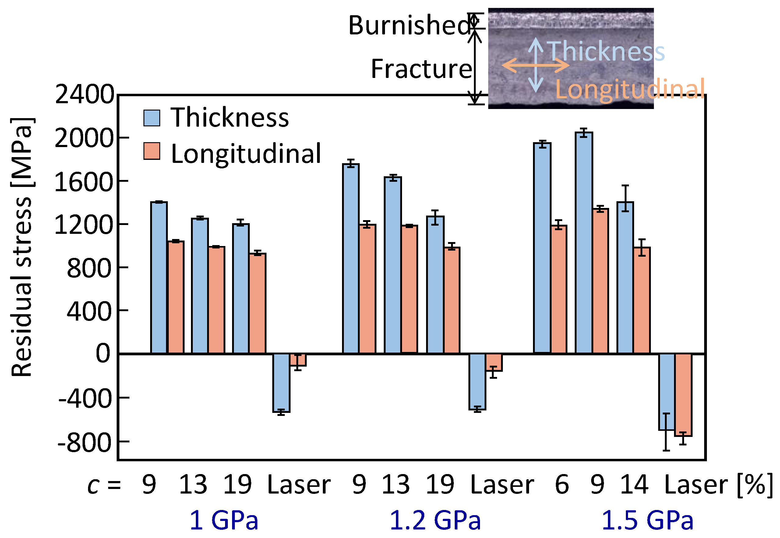
2.3. Effect of Quality of Sheared Edge on Fatigue Strength

The fatigue strength of forming parts is also influenced by the quality of the sheared edge [44,45,46]. An ultra-high strength steel plate having a tensile strength of 1610 MPa was manufactured by quenching and tempering a 0.35% carbon steel plate having a thickness of 4.5 mm, and the plate was punched for different clearance ratios. The surfaces of the sheared edge and the fatigue strength for the punched ultra-high strength steel plate are illustrated in Figure 4 [47]. With decreasing clearance ratio, the quality of the punched edge becomes high, and thus the fatigue strength rises. For low quality of the sheared edge, the mechanical properties of formed parts deteriorate from inherent ones of materials.

3. Improvement of Quality of Sheared Edge

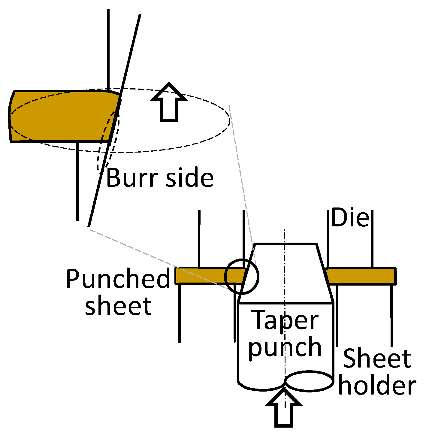
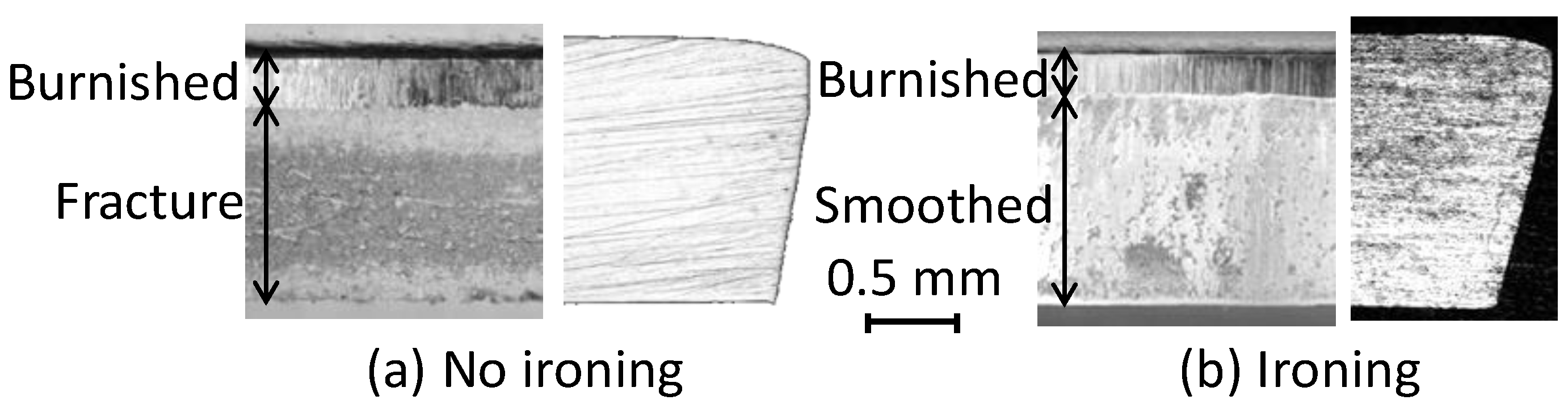
3.1. Ironing of Sheared Edge with Taper Punch

Although fine blanking is useful in improving the quality of the sheared edge, it is not easy to apply fine blanking to ultra-high strength steel sheets. The hole edge of a punched ultra-high strength steel sheet was smoothed by shaving the punched edge [48,49], and the hole limiting expansion is triply increased by shaving the edge, whereas the die life of shaving is comparatively short and the removal of chips is additionally required. The limiting hole expansion ratio is increased by punching high strength steel sheets with a double-beveling punch [50].
An ironing process of a punched edge with a taper punch is shown in Figure 5, and the surfaces and cross-sections of the edges without and with ironing for the punched 980 MPa dual phase ultra-high strength steel sheet of a clearance ratio of 20% are illustrated in Figure 6 [37]. The punched edge undergoes large shear deformation under highly compressive stresses during ironing, and the quality of the sheared edge is improved by smoothing the rough fracture surface. The angle of the taper punch was set to be similar to the tilt of the fracture surface. The sheared edge of the punched 980 MPa ultra-high strength steel sheet was successfully ironed with the taper punch. Since the fracture surface changed to the smooth surface, the limiting hole expansion ratio increased. The ironing process with a taper punch was applied to stretch flanging to increase the formability [37].

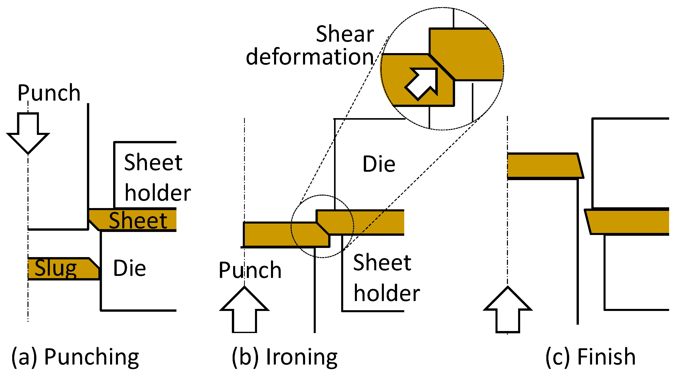
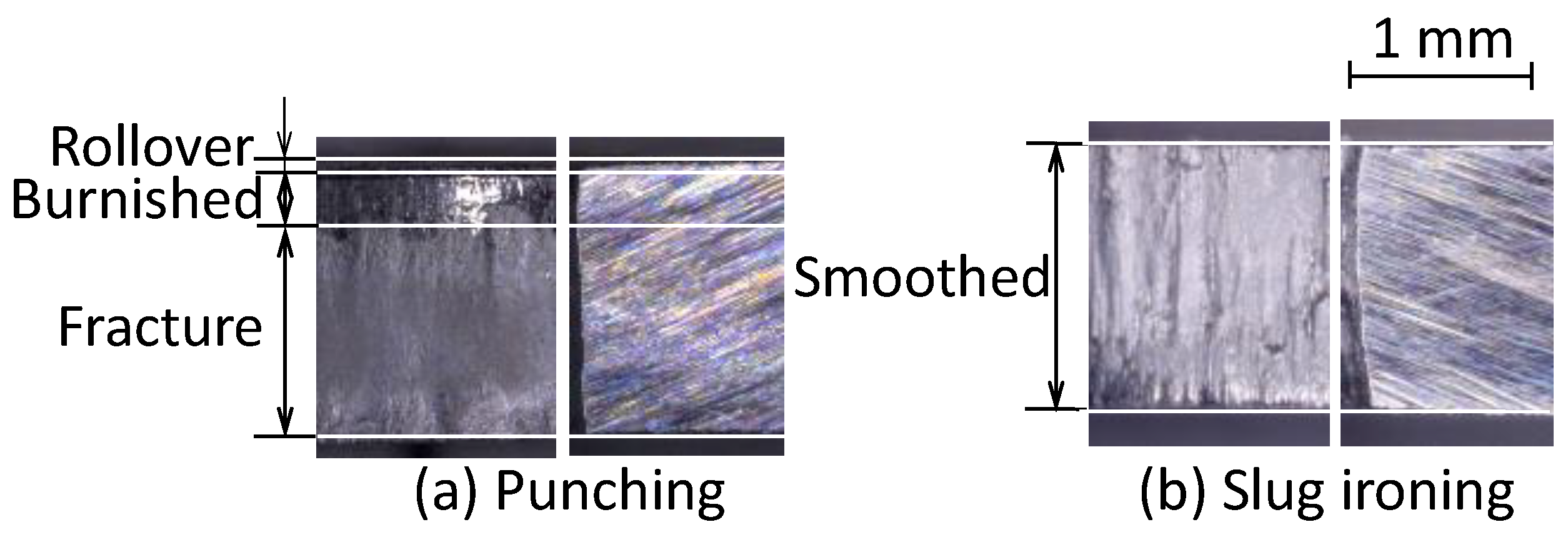
3.2. Ironing of Sheared Edge with Punched Slug

Instead of the taper punch, a punched slug was employed to iron the punched edge. The sheet is punched, and then the punched hole is ironed by passing the punched slug to improve the quality of the punched edge, as shown in Figure 7 [51]. This process is similar to the ironing process with a taper punch, and large shear deformation is applied under a highly compressive stress to the punched edge. Since both fracture surfaces of the hole and slug are inclined by the clearance between the punch and die, the hole edge is ironed. This process makes useful use of the waste slug ejected from punching, and is economical, whereas the setting of the slug in the punched hole is not easy.
A 1500 MPa ultra-high strength steel sheet was punched, and then was ironed with the punched slug. The 1500 MPa sheet was made of die quenching of a 22MnB5 steel sheet conventionally employed for hot stamping, i.e., a press-hardened steel sheet, and the sheet was similar martensite steel to commercial 1500 MPa ultra-high strength steel sheets used for cold stamping. The surfaces and cross-sections of the edges without and with slug ironing for the punched 1500 MPa ultra-high strength steel sheet of a 10% clearance ratio are shown in Figure 8 [52]. The fracture surface of the punched edge is smoothed by ironing. Although high tensile residual stress acted around the punched edge, the residual stress was changed to compressive one by slug ironing.

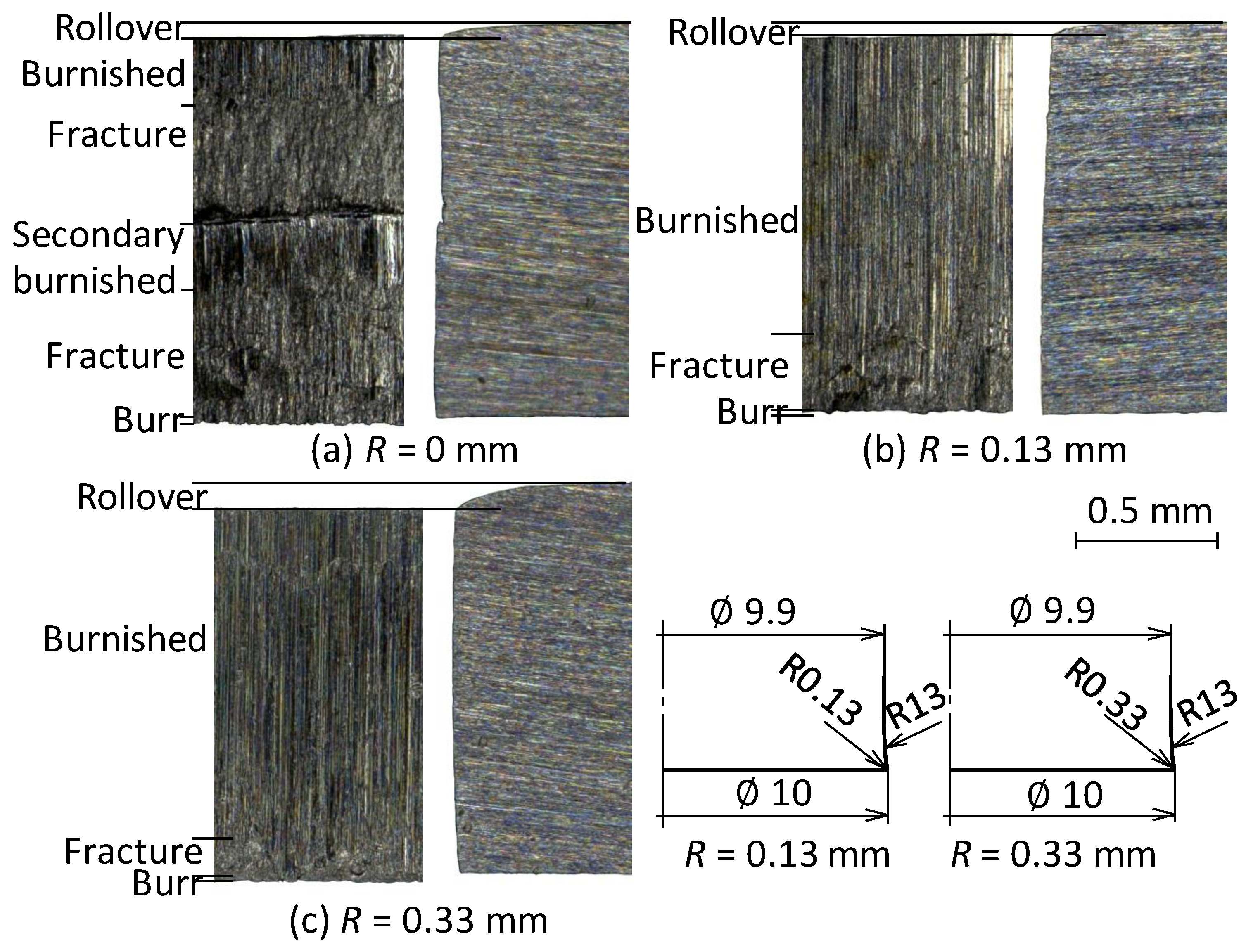
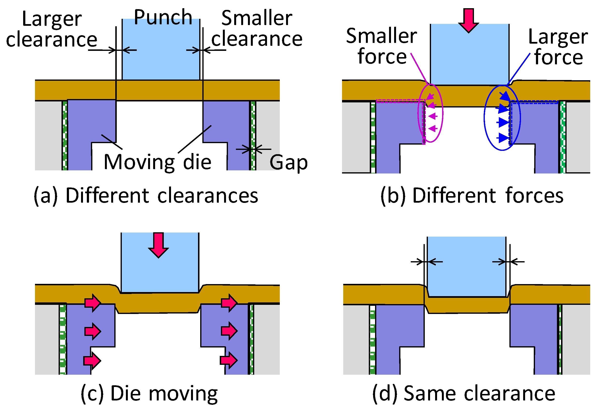
3.3. Slight Clearance Punching with Punch Having Small Round Corner

The quality of the punched edge generally improves with decreasing clearance ratio. By the slight clearance below a clearance ratio of 1%, the tensile stress during punching is decreased, and thus the initiation of cracks becomes late even for ultra-high strength steel sheets having low ductility. In slight clearance punching, however, sharp edges of the punch and die are likely to chip, and the tool wear becomes remarkable [53]. A punch having a small chamfer is useful for punching a thick high strength steel plate under a slight clearance [54].
For slight clearance punching, the secondary burnished surface appears for the ultra-high strength steel sheets, as shown in Figure 2b. To prevent the secondary burnished surface, a slight clearance punching process with a punch having a small round corner has been developed [55]. The surfaces and cross-sections of the punched edges of the 980 MPa dual phase sheets with the punch having small round corner for a clearance ratio of 0.8% are illustrated in Figure 9. Since the cracks are generated from both corners of the punch and die for a corner radius of R = 0 mm, the secondary burnished surface is caused, and a step appears around the boundary with the fracture surface. For R = 0.13 and 0.33 mm, the fine surface is gained by crack propagation only from die corner, and the secondary burnished surface disappears. Although hydrogen-induced delayed cracking is likely to occur in shearing of the ultra-high strength steel sheets, no cracking occurred for the slight clearance punching process with the punch having a small round corner. In addition, the punch and die hardly chip for the punch having a small round edge.
Since the setting of the slight clearance punching process with the punch having a small round corner is not easy, a punching process using automatic centring with a moving die was proposed (see Figure 10) [56]. The punch and moving die are initially eccentric, i.e., the left and right clearances between the punch and die are not the same. In this process, the slight gap is located between the moving die and die holder, and the die is moved by the action of force. When the left and right clearance are different, an imbalanced force acts to the moving die, and then the moving die shifts in order to decrease the imbalanced force. After some shots, the punch and die become concentric.

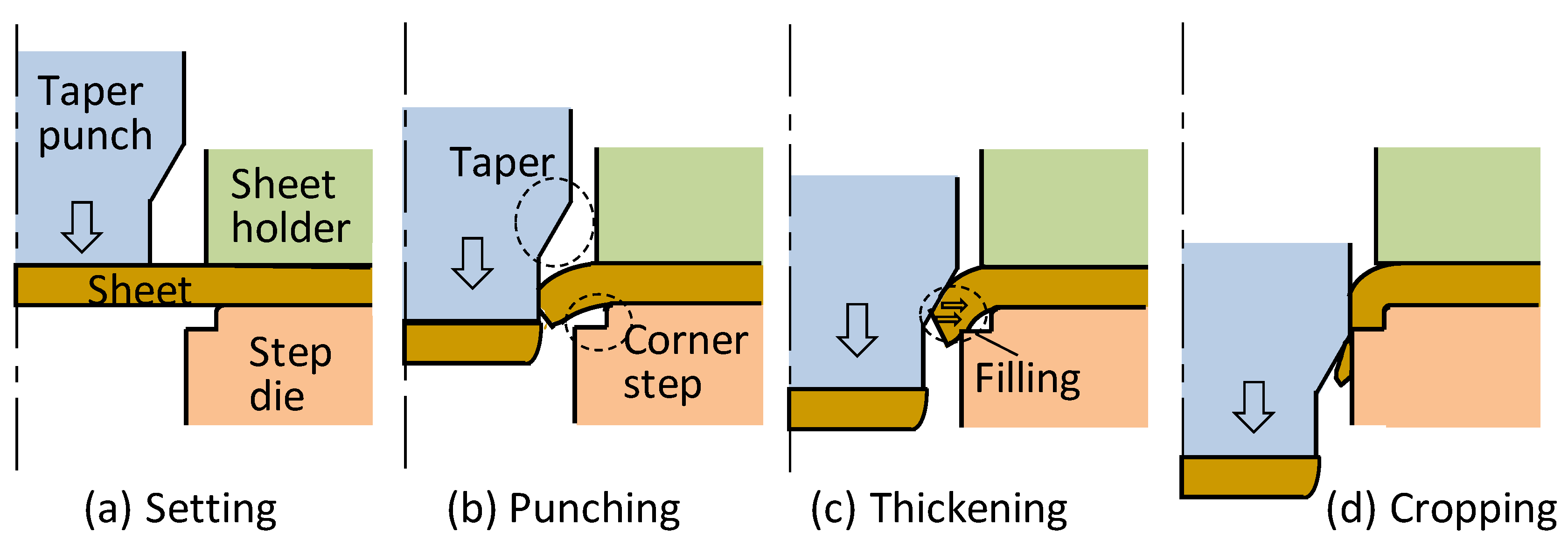
3.4. Thickening of Sheared Edge

A punching process of a thickened sheared edge was developed to improve the fatigue strength and the stiffness of the punched ultra-high strength steel sheet, as shown in Figure 11 [57,58]. A pair of taper punch and step die is employed to thicken the sheared edge in one shot punching. The sheet is first punched under tension stress with the taper punch and step die. Subsequently, the sheared edge is flanged into the corner step of the die with the taper punch, and the fracture surface of the sheared edge is smoothed by ironing with the taper punch. After sufficiently filling the cavity of the corner step of the die, the hole is cropped. Although the diameter of the firstly punched hole is smaller than that of the desired hole, the hole is formed into the desired one by the subsequent thickening stage. A part of the punched slug is efficiently utilized as a material for thickening the edge. Although the stress concentrates around the punched edge in loading of the punched sheet, the stress concentration is relieved by thickening. The present punching process can be easily installed in stamping operations.
The stress is likely to concentrate around concave portions of sheet-metal parts in loading. The concave portions were locally thickened with pairs of taper punch and step die similar to those shown in Figure 11, and the fatigue strength and stiffness of an ultra-high strength steel part were improved [59]. Local thickening is effective for avoiding the stress concentration occurring around sheared edges.

4. Hydrogen-Induced Delayed Fracture of Sheared Ultra-High Strength Steels
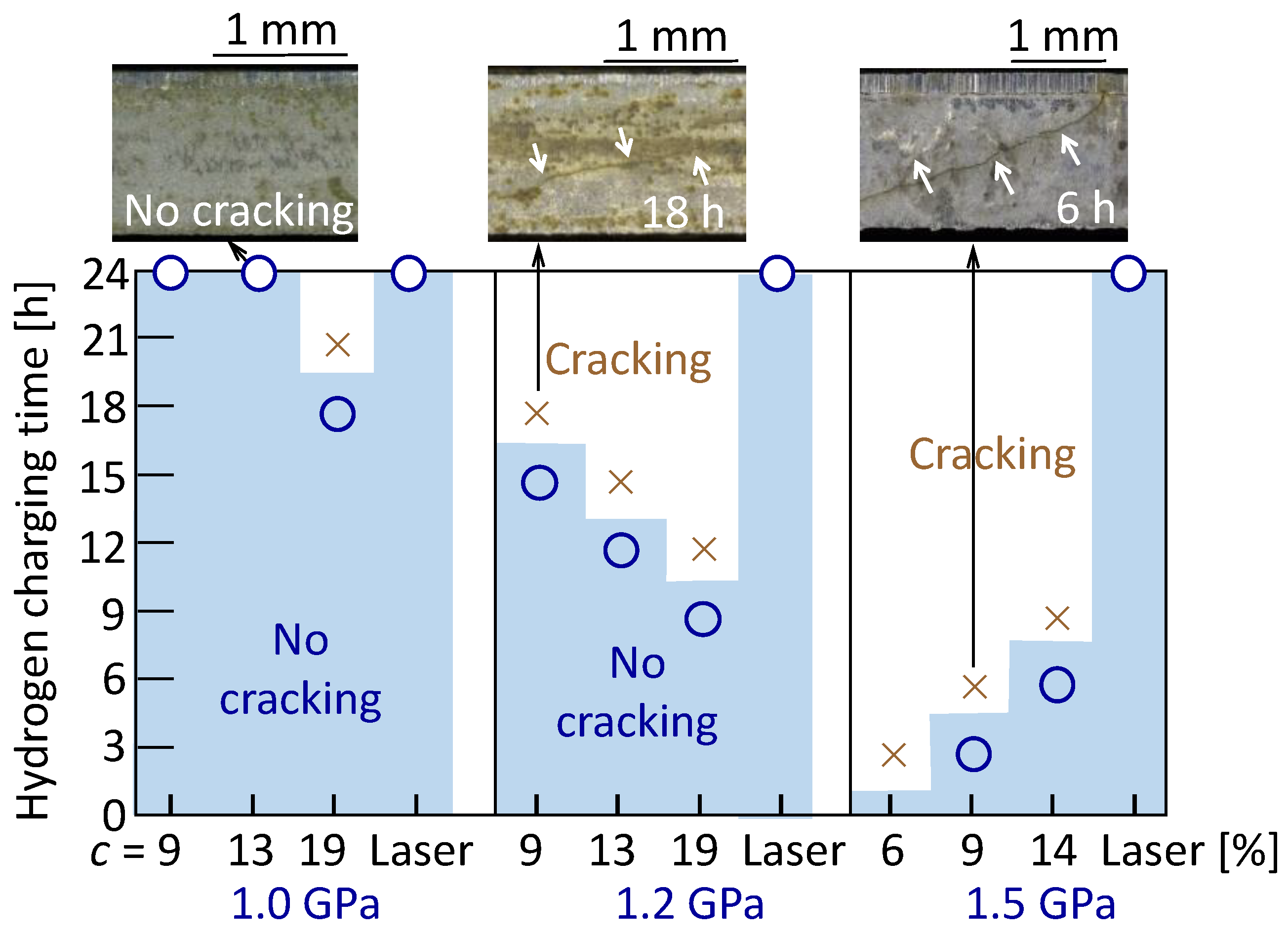
4.1. Cold Shearing

In the hydrogen-induced delayed fracture, steel workpieces are fractured without plastic deformation by diffusing hydrogen with time. Most of researches about the delayed fracture have dealt with bolts and fasteners having high strength [60], because the delayed fracture is caused by a high tensile stress acting on tightened ones. The delayed fracture appears also for the ultra-high strength steel sheets above 1 GPa in tensile strength, particularly for the 1.5 GPa sheet [61,62,63], and the risk level of delayed fracture becomes large with increasing tensile stress [64]. For industrial application of 1.5 GPa steel sheets, it is required to prevent the occurrence of delayed fracture. In cold shearing of the ultra-high strength steel sheets, plastic deformation is large, the tensile residual stress is high, and the sheared edge quality is low. Thus, the risk level of the delayed fracture rises [65].
High tensile residual stress is caused on the fracture surfaces of the sheared edges of the cold-blanked ultra-high strength steel sheets, as shown in Figure 12 [66], where 1 GPa and 1.2 GP sheets are made of dual phase steel and 1.5 GPa sheet is made of martensite steel. On the other hand, the residual stress acting on the surface of laser-cut edges is compressive. The delayed fracture results from the tensile residual stress.
Although no cracks appeared on the surfaces of blanked edges, delayed cracking was caused on the fracture surface by cathode hydrogen charging, as shown in Figure 13 [66]. The cracking time decreases with increasing sheet strength, and the risk level for the cold-blanked 1.5 GPa sheets considerably rises. On the other hand, for laser cutting, no cracks occurred after hydrogen charging because of the compressive residual stress. In addition, the processes for improving the quality of the sheared edge described in Chapter 3 have the function of preventing delayed cracking, because the residual stress is reduced.

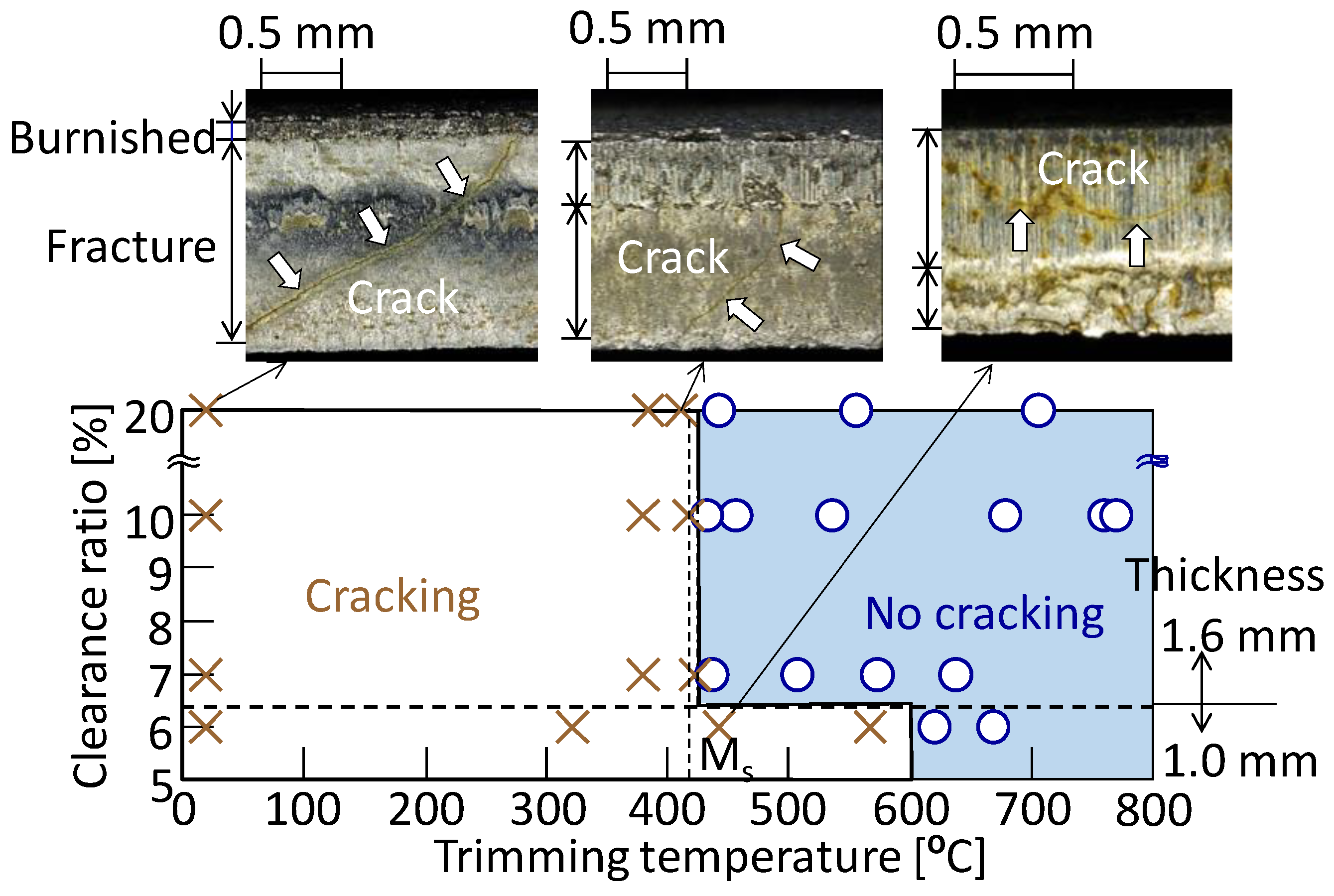
4.2. Hot Press Trimming in Hot Stamping

Ultra-high strength steel components having about 1.5 GPa in tensile strength are produced by hot stamping, [67]. Quenchable steel sheets are transformed into austenite by heating to about 900 °C, and the heated sheets are transformed into hard martensite by holding at the bottom dead centre of a press just after forming. The quenchable steel sheets are not ultra-high strength steel sheets used for cold stamping, and the strength is increased by die quenching. Although the springback in cold stamping of ultra-high strength steel sheets is considerably large, the springback in hot stamping is small, and thus the dimensional accuracy of the hot-stamped components is remarkably high [68].
A big drawback of hot stamping is high-cost laser trimming [67]. In cold press trimming of hot-stamped components, however, the tool life is short, the quality of sheared edges is low and the risk of delayed fracture is high as well as cold shearing of ultra-high strength steel sheets [69,70]. Laser trimming is partly replaced with hot press trimming included in hot stamping operations [71]. In hot trimming, formed components are sheared under a hot and soft situation just after the start of die quenching, and thus the drawbacks in laser trimming and cold press trimming are solved.
In hot press trimming, it is not easy to control the trimming temperature, because the temperature rapidly drops during forming and die quenching. Although the delayed fracture does not occur at high trimming temperatures [72], the risk at low temperatures is high. The effect of the trimming temperature in hot press trimming on the occurrence of hydrogen-induced delayed cracking was examined [73]. Since the tensile residual stress was high below the martensite transformation start temperature of 420 °C, delayed cracking occurred on rough fracture surfaces of the sheared edges, as shown in Figure 14. For the thin sheet having a thickness of 1.0 mm, the critical temperature increased to 600 °C.

5. Conclusions

The increase in strength of steel sheets used for automobiles is still required to improve lightweighting and collision safety, and next-generation 1.5 GPa ultra-high strength steel sheets having a total elongation of about 20% have been developed in some steel makers. Most of 1.5 GPa ultra-high strength steel automobile components are currently produced by hot stamping processes, and expensive equipment and low productivity are drawbacks. Although the application of cold stamping processes would spread for practical use of the next-generation 1.5 GPa sheets, die failures are severely problematic, and it is necessary to develop not only new die materials but also new coatings.
In shearing processes of high-strength steel sheets, the risk of hydrogen-induced delayed fracture grows with increasing strength. The processes for improving the quality of sheared edges shown in Chapter 3 are useful in preventing the delayed fracture, because the compressive residual stress is generated around the sheared edges. In addition, the use of expensive laser trimming generally used for hot-stamped parts may be reduced by the application of these processes. Conversely, laser blanking is introduced to cold stamping of ultra-high strength steel sheets, because the residual stress around blanked edges is compressive as shown in Figure 12. Laser blanking is die-less and flexible, and the time of laser blanking approaches the time of press blanking. Although the equipment of laser blanking is very expensive, the cost reduction is expected.

Funding

This paper is based on results obtained from a project commissioned by the New Energy and Industrial Technology Development Organization (NEDO).

Conflicts of Interest

The author declares no conflict of interest.

References

  1. Tisza, M.; Czinege, I. Comparative study of the application of steels and aluminium in lightweight production of automotive parts. Int. J. Lightweight Mater. Manuf. 2018, 1–4, 229–238. [Google Scholar] [CrossRef]
  2. Billur, M.S.; Altan, T. Challenges in forming advanced high strength steels. In Proceedings of the New Developments in Sheet Metal Forming, Fellbach, Germany, 22–23 May 2012; pp. 285–304. [Google Scholar]
  3. Mori, K.; Akita, K.; Abe, Y. Springback behaviour in bending of ultra-high-strength steel sheets using CNC servo press. Int. J. Mach. Tools Manuf. 2007, 47, 321–325. [Google Scholar] [CrossRef]
  4. Komgrit, L.; Hamasaki, H.; Hino, R.; Yoshida, F. Elimination of springback of high-strength steel sheet by using additional bending with counter punch. J. Mater. Process. Technol. 2016, 229, 199–206. [Google Scholar] [CrossRef]
  5. Bahloul, R.; Ben-Elechi, S.; Potiron, A. Optimisation of springback predicted by experimental and numerical approach by using response surface methodology. J. Mater. Process. Technol. 2006, 173, 101–110. [Google Scholar] [CrossRef]
  6. Sumikawa, S.; Ishiwatari, A.; Hiramoto, J.; Urabe, T. Improvement of springback prediction accuracy using material model considering elastoplastic anisotropy and Bauschinger effect. J. Mater. Process. Technol. 2016, 230, 1–7. [Google Scholar] [CrossRef]
  7. Yang, X.A.; Ruan, F. A die design method for springback compensation based on displacement adjustment. Int. J. Mech. Sci. 2011, 53, 399–406. [Google Scholar] [CrossRef]
  8. Kaupper, M.; Merklein, M. Bendability of advanced high strength steels—A new evaluation procedure. CIRP Ann. Manuf. Technol. 2013, 62, 247–250. [Google Scholar] [CrossRef]
  9. Cora, Ö.N.; Ağcayazı, A.; Namiki, K.; Sofuoğlu, H.; Koç, M. Die wear in stamping of advanced high strength steels—Investigations on the effects of substrate material and hard-coatings. Tribol. Int. 2012, 52, 50–60. [Google Scholar] [CrossRef]
  10. Wang, X.Z.; Masood, S.H. Investigation of die radius arc profile on wear behaviour in sheet metal processing of advanced high strength steels. Mater. Des. 2011, 32, 1118–1128. [Google Scholar] [CrossRef]
  11. Kim, H.; Altan, T.; Yan, Q. Evaluation of stamping lubricants in forming advanced high strength steels (AHSS) using deep drawing and ironing tests. J. Mater. Process. Technol. 2009, 209, 4122–4133. [Google Scholar] [CrossRef]
  12. Abe, Y.; Ohmi, T.; Mori, K.; Masuda, T. Improvement of formability in deep drawing of ultra-high strength steel sheets by coating of die. J. Mater. Process. Technol. 2014, 24, 1838–1843. [Google Scholar] [CrossRef]
  13. Ko, D.C.; Kim, S.G.; Kim, B.M. Influence of microstructure on galling resistance of cold-work tool steels with different chemical compositions when sliding against ultra-high-strength steel sheets under dry condition. Wear 2015, 338, 362–371. [Google Scholar] [CrossRef]
  14. Levy, B.S.; Van Tyne, C.J. Review of the shearing process for sheet steels and its effect on sheared-edge stretching. J. Mater. Eng. Perform. 2012, 21, 1205–1213. [Google Scholar] [CrossRef]
  15. Shivpuri, R.; Singh, S.; Agarwal, K.; Liu, C. Energy release rate based approach for the wear of punches in precision blanking of high strength steel. CIRP Ann. Manuf. Technol. 2011, 60, 307–310. [Google Scholar] [CrossRef]
  16. Mackensen, A.; Golle, M.; Golle, R.; Hoffmann, H. Experimental investigation of the cutting force reduction during the blanking operation of AHSS sheet materials. CIRP Ann. Manuf. Technol. 2010, 59, 283–286. [Google Scholar] [CrossRef]
  17. Mori, K.; Saito, S.; Maki, S. Warm and hot punching of ultra high strength steel sheet. CIRP Ann. Manuf. Technol. 2008, 57, 321–324. [Google Scholar] [CrossRef]
  18. Mori, K.; Maeno, T.; Fuzisaka, S. Punching of ultra-high strength steel sheets using local resistance heating of shearing zone. J. Mater. Process. Technol. 2012, 212, 534–540. [Google Scholar] [CrossRef]
  19. Brecher, C.; Emonts, M.; Eckert, M.; Weinbach, M. Double sided irradiation for laser-assisted shearing of ultra high strength steels with process integrated hardening. Phys. Procedia 2014, 56, 1427–1435. [Google Scholar] [CrossRef] [Green Version]
  20. Abe, Y.; Okamoto, Y.; Mori, K.; Jaafar, H. Deformation behaviour and reduction in flying speed of scrap in trimming of ultra-high strength steel sheets. J. Mater. Process. Technol. 2017, 250, 372–378. [Google Scholar] [CrossRef]
  21. Shin, J.H.; Kim, M.S.; Kim, S.I.; Seo, S.J.; Choi, S.H. Examining the microtexture evolution in a hole-edge punched into 780 MPa grade hot-rolled steel. Mater. Charact. 2016, 118, 535–546. [Google Scholar] [CrossRef]
  22. Achouri, M.; Germain, G.; Santo, P.D.; Saidane, D. Experimental and numerical analysis of micromechanical damage in the punching process for high-strength low-alloy steels. Mater. Des. 2014, 56, 657–670. [Google Scholar] [CrossRef] [Green Version]
  23. Tanaka, T.; Hagihara, S.; Tadano, Y.; Yoshimura, S.; Inada, T.; Mori, T.; Fuchiwaki, K. Analysis of shear droop on cut surface of high-tensile-strength steel in fine-blanking process. Mater. Trans. 2011, 52, 447–451. [Google Scholar] [CrossRef]
  24. Han, X.; Yang, K.; Ding, Y.; Tan, S.; Chen, J. Numerical and experimental investigations on mechanical trimming process for hot stamped ultra-high strength. J. Mater. Process. Technol. 2016, 234, 158–168. [Google Scholar] [CrossRef]
  25. Wu, X.; Bahmanpour, H.; Schmid, K. Characterization of mechanically sheared edges of dual phase steels. J. Mater. Process. Technol. 2012, 212, 1209–1224. [Google Scholar] [CrossRef]
  26. Choi, H.S.; Kim, B.M.; Ko, D.C. Effect of clearance and inclined angle on sheared edge and tool failure in trimming of DP980 sheet. J. Mech. Sci. Technol. 2014, 28, 2319–2328. [Google Scholar] [CrossRef]
  27. Hamedon, Z.; Abe, Y.; Mori, K. Improvement of formability of high strength steel sheets in shrink flanging. IOP Conf. Ser. Mater. Sci. Eng. 2016, 114, 012001. [Google Scholar] [CrossRef] [Green Version]
  28. Hasegawa, K.; Kawamura, K.; Urabe, T.; Hosoya, Y. Effects of microstructure on stretch-flange-formability of 980 MPa grade cold-rolled ultra high strength steel sheets. ISIJ Int. 2004, 44, 603–609. [Google Scholar] [CrossRef]
  29. Teng, Z.K.; Chen, X.M. Edge cracking mechanism in two dual-phase advanced high strength steels. Mater. Sci. Eng. A 2014, 618, 645–653. [Google Scholar] [CrossRef]
  30. Shih, H.C.; Shi, M.F. An innovative shearing process for AHSS edge stretchability improvements. ASME J. Manuf. Sci. Eng. 2011, 133, 061018. [Google Scholar] [CrossRef]
  31. Takuda, H.; Ozawa, K.; Hama, T.; Yoshida, T.; Nitta, J. Forming limit prediction in bore expansion by combination of finite element simulation and ductile fracture criterion. Mater. Trans. 2009, 50, 1930–1934. [Google Scholar] [CrossRef] [Green Version]
  32. Takuda, H.; Hama, T.; Nishida, K.; Yoshida, T.; Nitta, J. Prediction of forming limit in stretch flanging by finite element simulation combined with ductile fracture criterion. Comput. Meth. Mater. Sci. 2009, 9, 137–142. [Google Scholar]
  33. Wang, K.; Greve, L.; Wierzbicki, T. FE simulation of edge fracture considering pre-damage from blanking process. Int. J. Solids Struct. 2015, 71, 206–218. [Google Scholar] [CrossRef]
  34. Paul, S.K.; Mukherjee, M.; Kundu, S.; Chandra, S. Prediction of hole expansion ratio for automotive grade steels. Comput. Mater. Sci. 2014, 89, 189–197. [Google Scholar] [CrossRef]
  35. Levy, B.S.; Van Tyne, C.J. Failure during sheared edge stretching. J. Mater. Eng. Perform. 2008, 17, 842–848. [Google Scholar] [CrossRef]
  36. He, J.; Li, S.; Dong, L. Experiments and FE simulation of edge cracking considering prehardening after blanking process. Int. J. Mater. Form. 2019. [Google Scholar] [CrossRef]
  37. Mori, K.; Abe, Y.; Suzui, Y. Improvement of stretch flangeability of ultra high strength steel sheet by smoothing of sheared edge. J. Mater. Process. Technol. 2010, 210, 653–659. [Google Scholar] [CrossRef]
  38. Matsuno, T.; Nitta, J.; Sato, K.; Mizumura, M.; Suehiro, M. Effect of shearing clearance and angle on stretch-flange formability evaluated by saddle-type forming test. J. Mater. Process. Technol. 2015, 223, 98–104. [Google Scholar] [CrossRef]
  39. Chang, Y.; Han, S.; Li, X.; Wang, C.; Zheng, G.; Dong, H. Effect of shearing clearance on formability of sheared edge of the third-generation automotive medium-Mn steel with metastable austenite. J. Mater. Process. Technol. 2018, 259, 216–227. [Google Scholar] [CrossRef]
  40. Karelova, A.; Krempaszky, C.; Werner, E.; Tsipouridis, P.; Hebesberger, T.; Pichler, A. Hole expansion of dual-phase and complex-phase AHS steels—Effect of edge conditions. Steel Res. Int. 2009, 80, 71–77. [Google Scholar]
  41. Pathak, N.; Butcher, C.; Worswick, M. Assessment of the critical parameters influencing the edge stretchability of advanced high-strength steel sheet. J. Mater. Eng. Perform. 2016, 25, 4919–4932. [Google Scholar] [CrossRef]
  42. Xu, L.; Barlat, F.; Lee, M.G.; Choi, K.S.; Sun, X. Hole expansion of dual phase steels. WIT Trans. Built Environ. 2012, 124, 75–83. [Google Scholar]
  43. Abe, Y.; Mori, K.; Norita, K. Gradually contacting punch for improving stretch flangeability of ultra-high strength steel sheets. CIRP Ann. Manuf. Technol. 2013, 62, 263–266. [Google Scholar] [CrossRef]
  44. Shiozaki, T.; Tamai, Y.; Urabe, T. Effect of residual stresses on fatigue strength of high strength steel sheets with punched holes. Int. J. Fatigue 2015, 80, 324–331. [Google Scholar] [CrossRef]
  45. Abe, Y.; Mori, K.; Kosaka, R. Improvement of fatigue strength of hole edge of ultra-high strength steel sheet by punching process including thickening. Key Eng. Mater. 2016, 716, 428–434. [Google Scholar] [CrossRef]
  46. Lara, A.; Picas, I.; Casellas, D. Effect of the cutting process on the fatigue behaviour of press hardened and high strength dual phase steels. J. Mater. Process. Technol. 2013, 213, 1908–1919. [Google Scholar] [CrossRef]
  47. Hamedon, Z.; Abe, Y.; Mori, K.; Nakagawa, N. Thickened holes edge including compressed rollover for improving tensile fatigue strength of thick sheet. Procedia Manuf. 2018, 15, 612–618. [Google Scholar] [CrossRef]
  48. Murakawa, M.; Suzuki, M.; Shionome, T.; Komuro, F.; Hara, A.; Matsumoto, A.; Koga, N. Precision piercing and blanking of ultrahigh-strength steel sheets. Procedia Eng. 2014, 81, 1114–1120. [Google Scholar] [CrossRef] [Green Version]
  49. Thipprakmas, S.; Sontamino, A. Fabrication of clean cut surface on high strength steel using a new shaving die design. J. Mech. Sci. Technol. 2020, 34, 301–317. [Google Scholar] [CrossRef]
  50. Matsuno, T.; Sato, K.; Okamoto, R.; Mizumura, M.; Suehiro, M. Synergy effect of shear angle and anisotropic material ductility on hole-expansion ratio of high-strength steels. J. Mater. Process. Technol. 2016, 230, 167–176. [Google Scholar] [CrossRef]
  51. Yasutomi, T.; Yonemura, S.; Yoshida, T.; Mizumura, M.; Hiwatashi, S. Blanking method with aid of scrap to reduce tensile residual stress on sheared edge. J. Phys. Conf. Ser. 2017, 896, 012098. [Google Scholar] [CrossRef] [Green Version]
  52. Mori, K.; Abe, Y.; Murai, Y. Prevention of delayed cracking of punched 1.5 GPa ultra-high strength steel sheets by ironing with punched slug. Int. J. Adv. Manuf. Technol. submitted.
  53. Chumrum, P.; Koga, N.; Premanond, V. Experimental investigation of energy and punch wear in piercing of advanced high-strength steel sheet. Int. J. Adv. Manuf. Technol. 2015, 79, 1035–1042. [Google Scholar] [CrossRef]
  54. Matsuno, T.; Kuriyama, Y.; Murakami, H.; Yonezawa, S.; Kanamaru, H. Effects of punch shape and clearance on hole expansion ratio and fatigue properties in punching of high strength steel sheets. Steel Res. Int. 2010, 81, 853–856. [Google Scholar]
  55. Mori, K.; Abe, Y.; Kidoma, Y.; Kadarno, P. Slight clearance punching of ultra-high strength steel sheets using punch having small round edge. Int. J. Mach. Tools Manuf. 2013, 65, 41–46. [Google Scholar] [CrossRef]
  56. Jaafar, H.; Mori, K.; Abe, Y.; Nakanishi, K. Automatic centring with moving die for cold small clearance punching of die-quenched steel sheets. J. Mater. Process. Technol. 2016, 227, 190–199. [Google Scholar] [CrossRef]
  57. Kadarno, P.; Mori, K.; Abe, Y.; Abe, T. Flanging using step die for improving fatigue strength of punched high strength steel sheet. Procedia Eng. 2014, 81, 1133–1138. [Google Scholar] [CrossRef] [Green Version]
  58. Kadarno, P.; Mori, K.; Abe, Y.; Abe, T. Punching process including thickening of hole edge for improvement of fatigue strength of ultra-high strength steel sheet. Manuf. Rev. 2014, 1, 4. [Google Scholar] [CrossRef] [Green Version]
  59. Abe, Y.; Fujisawa, Y.; Murai, Y.; Mori, K. Thickening process of concave edge for increasing stiffness and fatigue strength of ultra-high strength steel sheets. Procedia Manuf. 2018, 15, 605–611. [Google Scholar] [CrossRef]
  60. Kuduzović, A.; Poletti, M.C.; Sommitsch, C.; Domankova, M.; Mitsche, S.; Kienreich, R. Investigations into the delayed fracture susceptibility of 34CrNiMo6 steel, and the opportunities for its application in ultra-high-strength bolts and fasteners. Mater. Sci. Eng. A 2014, 590, 66–73. [Google Scholar] [CrossRef]
  61. Gu, J.L.; Chang, K.D.; Fang, H.S.; Bai, B.Z. Delayed fracture properties of 1500 MPa bainite/martensite dual-phase high strength steel and its hydrogen traps. ISIJ Int. 2002, 42, 1560–1564. [Google Scholar] [CrossRef] [Green Version]
  62. Liu, Q.; Zhou, Q.; Venezuela, J.; Zhang, M.; Atrens, A. Hydrogen influence on some advanced high-strength steels. Corros. Sci. 2017, 125, 114–138. [Google Scholar] [CrossRef]
  63. Venezuela, J.; Zhou, Q.; Liu, Q.; Li, H.; Zhang, M.; Dargusch, M.S.; Atrens, A. The influence of microstructure on the hydrogen embrittlement susceptibility of martensitic advanced high strength steels. Mater. Today Commun. 2018, 17, 1–14. [Google Scholar] [CrossRef]
  64. Takashima, K.; Yoshioka, Y.; Yokoyama, K.; Funakawa, Y. Hydrogen embrittlement behavior of ultra-high strength dual phase steel sheet under sustained tensile-loading test. ISIJ Int. 2018, 58, 173–178. [Google Scholar] [CrossRef] [Green Version]
  65. Yoshino, M.; Ohji, Y.; Takagi, S.; Hasegawa, K. Influence of sheared edge on hydrogen embrittlement resistance in an ultra-high strength steel sheet. ISIJ Int. 2014, 54, 1416–1425. [Google Scholar] [CrossRef] [Green Version]
  66. Mori, K.; Abe, Y.; Sedoguchi, K. Delayed fracture in cold blanking of ultra-high strength steel sheets. CIRP Ann. Manuf. Technol. 2019, 68, 297–300. [Google Scholar] [CrossRef]
  67. Mori, K.; Bariani, P.F.; Behrens, B.A.; Brosius, A.; Bruschi, S.; Maeno, T.; Merklein, M.; Yanagimoto, J. Hot stamping of ultrahigh strength steel parts. CIRP Ann. Manuf. Technol. 2017, 66, 755–777. [Google Scholar] [CrossRef]
  68. Nakagawa, Y.; Mori, K.; Maeno, T. Springback-free mechanism in hot stamping of ultra-high-strength steel parts and deformation behaviour and quenchability for thin sheet. Int. J. Adv. Manuf. Technol. 2018, 95, 459–467. [Google Scholar] [CrossRef]
  69. So, H.; Faßmann, D.; Hoffmann, H.; Golle, R.; Schaper, M. An investigation of the blanking process of the quenchable boron alloyed steel 22MnB5 before and after hot stamping process. J. Mater. Process. Technol. 2012, 212, 437–449. [Google Scholar] [CrossRef]
  70. Nothhaft, K.; Suh, J.; Golle, M.; Picas, I.; Casellas, D.; Volk, W. Shear cutting of press hardened steel: Influence of punch chamfer on process forces, tool stresses and sheared edge qualities. Prod. Eng. Res. Devel. 2012, 6, 413–420. [Google Scholar] [CrossRef]
  71. Hou, H.; Li, H.; He, L. Effect of technological parameters on microstructure and accuracy of B1500HS steel parts in the hot blanking. Int. J. Adv. Manuf. Technol. 2018, 95, 3275–3287. [Google Scholar] [CrossRef]
  72. Matsuno, T.; Sekito, Y.; Kawasaki, K. Microstructure characterization of fine grains near hot-sheared surface formed during hot-stamping process. J. Mater. Process. Technol. 2016, 229, 570–581. [Google Scholar] [CrossRef]
  73. Nakagawa, Y.; Mori, K.; Maeno, T.; Umemiya, R. Delayed cracking in hot stamping with hot trimming for ultra-high strength steel components. Int. J. Adv. Manuf. Technol. 2019, 105, 5081–5090. [Google Scholar] [CrossRef]
Figure 1. Relationship between total elongation and tensile strength for various commercial steel sheets.
Jmmp 04 00054 g001
Figure 2. Surfaces and cross-sections of punched edges for (a) 390 MPa (b) 980 MPa high strength steel sheets.
Jmmp 04 00054 g002
Figure 3. Effect of clearance ratio on cracking in stretch flanging (a) of 780 MPa dual phase steel sheet for (b) c = 15% (c) c = 25%.
Jmmp 04 00054 g003
Figure 4. Surfaces of sheared edge and fatigue strength for punched ultra-high strength steel plate for (a) punched strength and (b) fatigue strength [47].
Jmmp 04 00054 g004
Figure 5. Ironing process of punched edge with taper punch [37].
Jmmp 04 00054 g005
Figure 6. Surfaces and cross-sections of edges (a) without and (b) with ironing for punched 980 ultra-high strength steel sheet of 20% clearance ratio [37].
Jmmp 04 00054 g006
Figure 7. Ironing process of punched edge with slug ejected from punching; (a) punching, (b) ironing (c) finish.
Jmmp 04 00054 g007
Figure 8. Surfaces and cross-sections of edges (a) without and (b) with slug ironing for punched 1500 MPa ultra-high strength steel sheet of 10% clearance ratio [52].
Jmmp 04 00054 g008
Figure 9. Surfaces and cross-sections of punched edges of 980 MPa sheets with punch having small round corner for clearance ratio of 0.8% of (a) R = 0 mm, (b) R = 0.13 mm and (c) R = 0.33 mm [55].
Jmmp 04 00054 g009
Figure 10. Slight clearance punching process with punch having small round corner using automatic centring with moving die; (a) different clearances, (b) different forces, (c) die moving and (d) same clearance [56].
Jmmp 04 00054 g010
Figure 11. Punching process of thickened sheared edge for improving fatigue strength and the stiffness of punched ultra-high strength steel sheet; (a) setting, (b) punching, (c) thickening and (d) cropping [58].
Jmmp 04 00054 g011
Figure 12. Residual stress at middle of fracture surface of sheared edges of cold-blanked ultra-high strength steel sheets [66].
Jmmp 04 00054 g012
Figure 13. Delayed cracking induced by cathodic hydrogen charging test of cold-blanked and laser-cut ultra-high strength steel sheets [66].
Jmmp 04 00054 g013
Figure 14. Delayed cracking induced by cathodic hydrogen charging test of hot-trimmed 22MnB5 quenchable steel sheet [73].
Jmmp 04 00054 g014

