Article

Effects of Machining Parameters on Finishing Additively Manufactured Nickel-Based Alloy Inconel 625

1
Department of Industrial and Systems Engineering, Rutgers University, Piscataway, NJ 08854, USA
2
School of Mechanical Engineering, Tianjin University, Tianjin 300345, China
3
School of Mechanical & Automotive Engineering, Qingdao University of Technology, 777 Jialingjiang East Road, Qingdao 266525, China
*
Author to whom correspondence should be addressed.
J. Manuf. Mater. Process. 2020, 4(2), 32; https://doi.org/10.3390/jmmp4020032
Submission received: 7 April 2020 / Revised: 15 April 2020 / Accepted: 16 April 2020 / Published: 21 April 2020

Abstract

:
Metal additive manufacturing processes such as selective laser melting (SLM), laser powder bed fusion (L-PBF), electron beam melting (EBM) and laser metal deposition (LMD) can produce additively manufactured nearly fully dense parts with high geometrical complexity. These are often used as components in automotive, aerospace and medical device industries. Finish machining of these components is required to achieve the desired surface finish and dimensional tolerances. The investigations on additively manufactured alloys, as reported in the literature, indicate that a layer-wise scan strategy (orthogonal or layer-to-layer rotation) and process parameters have significant influences on the resultant microstructure which affects the final mechanical properties and fatigue life. The solidification microstructure depicts that growth directions of columnar grains and sizes of cellular grains that are affected by the layer-wise scan strategy. This paper presents experimental investigations on finish milling parameters on a nickel-based alloy manufactured with L-PBF using two distinct layer-wise scan strategies. The results reveal some effects of milling direction against the layer-wise build direction. The effects of cutting speed and feed rate on resultant cutting forces, chip formation, as well as surface finish at various cutting orientations in nickel-based alloy workpieces are reported.

1. Introduction

Heat resistant alloys are excellent metal materials since they retain their hardness and strength at elevated temperatures. These alloys include the titanium alloys (e.g., Ti-6Al-4V (Ti64), Ti-5Al-5V-5Mo-3Cr) and the nickel-based alloys (e.g., Inconel 718, Inconel 625, Rene 142) with wide ranging applications in various industries [1,2]. The conventional manufacturing methods for these alloys consist of forming and casting into blanks at first and then machining to their ultimate form. For this reason, cutting processes which affect resultant surface integrity and alter their subsurface microstructure have been studied extensively [1,2,3,4]. Particularly, proper machining of nickel-based alloys is known to be very challenging yet highly important. The machining-induced surface morphology reveals a considerable level of alteration to the microstructure of the machined surface that is significantly affected by cutting tool material, geometry, cutting conditions, applications of various cooling and lubricating methods [2]. In recent years, additive manufacturing (AM) of these alloys from powder material by using powder bed fusion (PBF) processes such as selective laser sintering (SLS), electron beam melting (EBM) and selective laser melting (SLM) have been adopted to fabricate products to increase flexibility and reduce the production cost [5,6]. Although AM technologies can result in a near net-shape geometry for additively manufactured parts, finish machining processes are still needed to achieve desired surface finish and dimensional tolerances [7,8,9,10,11]. Therefore, machinability of additively manufactured titanium-based alloys and nickel-based superalloys has gained attention recently from the research community. It has been found that microstructure of additively manufactured alloys is quite different from wrought or cast counterparts. In wrought or cast alloys and superalloys, microstructure usually contains equiaxed grains after proper heat treatment and the grain size can be considered uniform [12].
On the other hand, the microstructure in additively manufactured titanium alloy Ti64 obtained through SLS [13] and EBM [14] and the microstructure of additively manufactured nickel-based alloys Inconel 625 and Rene 142 [14] exhibit columnar grain growth along build direction (B, along the z direction) as observed in 3D optical microscopy imaging. In laser powder bed fusion (L-PBF) of nickel alloy Inconel 625, Arisoy et al. [15] have found that their microstructure is highly dependent on the build direction (BD), and the grain growth is along the BD with a deviation angle. However, cellular grains are seen on surfaces orthogonal to build direction. It is reported that the yield strength of as-built L-PBF titanium alloy Ti64 in horizontal direction (XY) and in build direction (Z) is about 1140 ± 50 MPa and 1120 ± 80 MPa respectively [16], and similarly for nickel alloy Inconel 625, these values are reported as 725 MPa ± 50 MPa and 615 MPa ± 50 MPa respectively [17]. Shunmugavel [18] and Deng et al. [19] also found similar results for SLM manufactured Ti64 and Inconel 718, respectively. It is well-acknowledged that the microstructure of workpiece material has significant effects on their machinability, including the cutting forces, temperature, tool wear and surface integrity [20]. Shunmuavel et al. [18,21] have suggested that the BD induced microstructure difference can obviously affect the cutting forces during machining the SLM manufactured titanium alloy Ti64. The influence of microstructure due to build direction on the cutting forces during machining of additively manufactured maraging steel [22] and stainless steel [23] are also reported. Therefore, the machinability, including the cutting forces, tool wear, chip formation, and surface finish of additively manufactured metal alloys has been widely studied in literature.

2. Machining Induced Effects on Additively Manufactured Materials

Cutting forces generated in machining of additively manufactured metal alloys have been widely investigated and compared with wrought and cast counterparts. Le Coz et al. [24] found that higher cutting speed can result in lower cutting forces during micro-cutting of SLM manufactured titanium alloy Ti64. Shunmugavel et al. [18] compared cutting forces during turning of wrought (306 HV hardness and 948 MPa yield strength) and SLM manufactured hollow cylinder titanium alloy Ti64 samples (360 HV hardness and 1050 MPa yield strength) and observed that cutting forces are higher at all cutting speeds (up to 180 m/min) and excessive tool wear rapidly developing when machining SLM manufactured titanium alloy. They related this behavior to high strength and hardness. Shunmugavel et al. [25] observed higher cutting forces when cutting speed is increased to 180 m/min during turning SLM manufactured titanium alloy Ti64. Shunmugavel et al. [25] attributed this observation to the micro-impacts during cutting caused by porosity in the microstructure which was believed to be related to inappropriate selection of SLM process parameters. Imbrogno et al. [26] conducted turning experiments on titanium alloy Ti64 manufactured via direct metal laser sintering (DMLS) at various cutting speeds and feeds and stated that cutting forces increased when cutting speed increased from 50 to 110 m/min at a feed rate of 0.1 mm/rev but they began to decrease with increasing cutting speed when the feed rate was increased from 0.1 to 0.2 mm/rev. It has been confirmed by many researchers that the BD induced columnar grain growth direction can affect the cutting forces of additively manufactured metal alloys. Shunmuavel et al. [18,21] measured cutting forces under three different relative directions between the cutting velocity vector and the columnar grain directions, as illustrated in Figure 1. Highest cutting forces, including main cutting force and thrust force, were found when the cutting tool normally crossed the columnar grains (case 1 in Figure 1a), followed by the case of the cutter moving parallel to the columnar grains (case 3 in Figure 1c). The lowest cutting forces were obtained when the cutting tool moved along the cross-section of the columnar grains (case 2, Figure 1b). Guo et al. [23] showed that the resultant cutting force against the BD in finish milling of additively manufactured AISI 316L stainless steel via high power Directed Laser Deposition (DLD) is clearly larger than that along the BD. However, Fortunato et al. [22] found that the influence of BD on the cutting force during milling the SLM manufactured maraging steel components was varying under different cutting speeds.
The post-heat treatment can affect the cutting forces through changing the phase and microstructure and thus the mechanical properties of AM manufactured workpiece as well. Oyelola et al. [27] reported that the cutting force reduced by 40% under β annealed condition and 24% under α annealed condition compared to the ‘as built’ directed energy deposition (DED)-manufactured titanium alloy Ti64 at a low cutting speed (50 m/min). Fortunato et al. [22] compared the cutting forces during finish milling of SLM manufactured maraging steel samples with three different heat treatments, namely ‘as built’ sample, partially heated sample (heating at 815 °C for 1 h followed by air cooling) and fully treated sample (480 °C for 4 h followed by air cooling). It was found that the totally heated samples resulted in the highest cutting forces in transverse and axial directions, and the lowest value in feed direction.
In summary, the cutting forces of machining additively manufactured metal alloys have been investigated and compared against machining wrought or cast counterparts in many research studies. Many researchers experimented with higher cutting forces when machining additively manufactured workpiece, including titanium alloy Ti64, maraging steel and stainless steel, and they all suggested that the machinability of additively manufactured workpiece is rated poorer than wrought or cast counterparts.
The tool wear is severe during the machining of titanium alloys or nickel-based alloys and it will deteriorate the surface integrity. Therefore, the influencing factors on the tool wear and its mechanism in cutting additively manufactured titanium and nickel-based alloys have been investigated by many researchers. Shunmugavel et al. [18], Bordin et al. [28] all pointed out that higher cutting speed can lead to rapid tool wear while cutting additively manufactured metal alloys. Besides, Bordin et al. [28,29] also investigated the effect of cooling conditions, including cryogenic cooling, wet cooling, and dry cutting, on the tool wear during turning of the EBM manufactured titanium alloy Ti64, and found the smallest wear development when cryogenic cooling was used. Tool wear mechanism was also investigated. The major tool wear mechanism was found to be coating delamination, adhesion and abrasion during turning of SLM built titanium alloy Ti64 [18,30]. However, adhesion was found to be the main mechanism, in turning of EBM built titanium alloy Ti64 [29]. Sartori et al. [31] compared the tool wear mechanism during cutting the titanium alloy Ti64 manufactured by DMLS and EBM under dry and cryogenic cooling conditions. Although the adhesion and abrasion were found to be the most significant wear mechanisms during all cutting conditions for both DMLS and EBM manufactured titanium alloy Ti64, their extent depended on the cutting conditions. The cryogenic cooling was found to reduce the cutting temperature and thus avoid the occurrence of diffusion wear which is responsible for the crater formation. Besides, the abrasive and flank wear were also reduced under cryogenic cooling condition.
The chip formation during cutting the additively manufactured metal alloys was also different from the wrought or cast counterparts. Shunmugavel et al. [32] investigated the chip formation of SLM built titanium alloy Ti6Al-4V in detail. Their investigation showed that SLM manufactured samples were more prone to produce segmented chips compared with the wrought one, because of the cracks were commonly seen in the primary and secondary deformation zone. Coz et al. [24] compared the chips between the SLM built titanium alloy Ti64 and the cast counterpart during micro turning, chips of these two samples showed a similar deformation.
The effect of cutting conditions on the chip formation was also investigated by some researchers. Bordin et al. [29] investigated the chip morphology during turning of an EBM built titanium alloy Ti64 cylindrical bar under different cooling conditions. They found that the chip morphology was mainly affected by the cooling conditions rather than the cutting parameters. Shunmugavel et al. [21] investigated the impact of BD on the chip morphology during orthogonal cutting of SLM built titanium alloy Ti64. The results showed that nearly flat chips with less curling were observed when the cutter crossed through columnar grains (see Figure 1a, case 1), and the severely curled chips were observed when the cutter moved parallel to the columnar grains (see Figure 1c, case 3). Oyelola et al. [33] also discussed the chip morphology while turning of DMD manufactured titanium alloy Ti64 cylindrical tubes by using uncoated and coated cutting inserts. It was found that the chips were regularly shear banded with periodicity when coated cutter was used, while the chips obtained with uncoated cutter had more uneven geometry.
It is well acknowledged that the machined surface morphology has an important effect on the service performance of components, including fatigue life, wear resistance and corrosion resistance, and is closely related to cutting conditions. However, it has been stated that the microstructure of additively manufactured alloys is different from the cast or wrought counterparts, which makes the surface finish of the additively manufactured workpiece after machining be also different. Therefore, it necessary to deeply investigate the machined surface morphology of additively manufactured workpiece.
Surface roughness is a common measure to describe the topography of machined surfaces. Shunmugavel et al. [25], Polishetty et al. [34] and Huang et al. [35] compared the roughness of machined surfaces in SLM manufactured and wrought titanium alloy Ti64 respectively, and all found smaller surface roughness values (average surface roughness, Ra < 2 µm) for SLM-built titanium alloy Ti64 under the same cutting conditions. However, Shunmugavel et al. [18,30] found that although the roughness of machined surfaces in SLM built titanium alloy Ti64 was smaller (Ra < 1.5 µm) than the machined surfaces of the wrought alloy (1.5 µm < Ra < 3 µm) under the some cutting condition, but this was not always true for all other cutting conditions. The surface roughness of additively manufactured workpiece is also closely related to the cutting conditions. In general, the surface roughness decreases with the increasing of cutting speed [18,23,25,27,36], but increases with the increasing of feed rate [35,37] and depth of cut [21]. Cooling conditions also have effect on the surface roughness of additively manufactured workpiece. Sartori et al. [37] found that the surface roughness of DMLS built titanium alloy Ti64 under cryogenic cooling was generally higher than that obtained under dry cutting. This conflicts with the results of Bordin et al. [28], where they suggested that the cryogenic cooling resulted in lower values of surface roughness of EBM built titanium alloy Ti64 than dry or wet cutting conditions. Some researchers pointed out that the cryogenic cooling will result in lower surface roughness in machining EBM built titanium alloy Ti64 at severe cutting conditions but higher roughness at other cutting conditions [31,38]. The build direction also has some impact on the surface roughness. For high power DLD built stainless steel AISI 316L, the machined surface roughness of milling against the BD was higher than that milling along the BD [23].
Surface defects such as feed marks, material side flow, adhered materials, and smeared materials were also investigated. Sartori et al. [29,37] observed the surface after turning the EBM built titanium alloy Ti64 under different cooling conditions. In their investigation, surface defects including the material side flow, feed marks, long grooves and adhered particles were observed on the machined surface during wet turning, while the adhered chip fragments, long grooves, folds, severe material side flow and smeared materials were observed under dry cutting. The cryogenic cooling condition reduced these surface defects but resulted in wavy surface topography along the cutting direction and feed mark peaks on the machined surfaces.
Kaynak and Tascioglu [7] briefly examined the effect feed rate on improving surface roughness in machining by turning of SLM built IN 718 alloy. They reported that arithmetic average surface roughness of as-SLM built IN 718 can be lowered more than 90% with finish machining although increasing feed rate can result in surface work-hardening. Brown et al. [8] stated that little study has been done to characterize surface integrity of an as-built SLM part followed by machining, they found that microhardness varies with the scan direction and the use of coolant in the subsequent milling, and surface integrity can be significantly improved by milling process. Calleja et al. [9] evaluated the machinability of laser deposited Inconel 718 alloy for both for turning and milling operations. Tests are conducted for a cutting speed range between 60 and 100 m/min and depth of cut ranges between 0.1 and 0.3 mm/rev for the turning process, and feed rate ranges of 0.05 and 0.06 mm/tooth for the milling process. The cutting forces were found lower for cutting laser deposited nickel-based alloy but higher when heat treated.
Kim et al. [10] examined the development of tool wear in cutting of nickel-based alloy Inconel 718 and compared the additively manufactured material with wrought counterpart in a milling operation. A high tool wear was observed when milling wrought Inconel 718 but a lower tool wear was noticed additively manufactured Inconel 718 which was mainly because of the high porosity present in the structure. Additively manufactured Inconel 718 exhibited higher hardness but caused less tool wear. The manufacturing method, the SLM, created a build direction near the re-melting areas and these areas contributed to the wear development. It was concluded that the build direction plays a significant role in affecting the cutting process and tool wear.
Among the nickel-based alloys, nickel alloy Inconel 625 is also a widely accepted alloy material which is a solid solution strengthening superalloy and has drawn significant attention due to its excellent characteristics [39]. For this reason, AM technologies have also been applied to manufacture nickel alloy Inconel 625 components. Industrialization of AM for nickel alloy Inconel 625 has potential applications in turbine engine parts, exhaust systems, fuel systems, chemical and process industry parts, oil well, petroleum and natural gas industrial parts [17]. The machinability of additively manufactured nickel alloy Inconel 625 is also reported in the recent literature. However, the machinability of additively manufactured nickel alloy Inconel 625 has not yet been investigated fully in detail as much as Inconel 718. Fei et al. [40] reported some cutting force measurements in face milling of additively fabricated nickel alloy Inconel 625. They found that cutting forces are affected by build direction. Patel et al. [41] reported that cutting force measurements can be used for estimating yield strength of additively manufacturing alloys since they exhibit different yield strength in different directions [17].
In this paper, the effects of cutting parameters on the cutting forces, chip formation, surface finish, and tool wear are studied when finish machining of nickel-based alloy Inconel 625 that is manufactured via L-PBF technology. Finish milling operations in different cutting directions (horizontal and vertical) against the BD of the cubical workpiece samples are performed. The effects of cutting speed and feed rate on the cutting forces, chip formation, tool wear and surface morphology are broadly analyzed.

3. Additively Manufactured Nickel Alloy Inconel 625 Workpiece

Nearly fully dense nickel alloy Inconel 625 workpieces with squared top faces in 16 mm × 16 mm dimension and 15 mm in height were manufactured using the EOS M270 Direct Metal Laser Sintering machine [42]. In the powder bed, a gas atomized nickel alloy Inconel 625 powder (mean particle size of 35 μm and 55% packing density) was used with a fixed layer thickness of s = 20 µm during layer-wise additive fabrication process. These parts were built using a laser power of P = 195 W, a scan velocity of vs = 800 mm/s and a hatch distance of h = 0.10 mm and by using two distinct scan strategy rotation schemes i.e., orthogonal 90° and 67° layer-to-layer rotation of stripes. The parameters used for manufacturing the L-PBF specimens were fixed except that the scan strategy rotation was changed by keeping all other parameters same. The L-PBF process involves melting of the powder material and fusing together only the desired locations on the surface of the powder bed using a laser spot diameter of d = 0.1 mm. Laser scanning of each layer is divided up into several bands called ‘stripes’ that are arranged in various patterns covering the surface as [40].
In the built parts, 4 mm wide stripes/bands were employed, along which multiple tracks, separated by a hatch distance, were processed with the laser beam moving at a constant scan velocity. During the L-PBF process, stripe patterns were rotated layer-to-layer to attain uniform built. The scan or stripe pattern rotation strategies known to have distinct effects on the underlying texture and microstructure of the built parts, and as a result their properties and fatigue behavior are altered [43]. In addition, previous experimental studies on microstructure formation of nickel alloy Inconel 625 revealed these process effects on columnar grain growth directions and cellular grain sizes [10].
The surfaces of nickel alloy Inconel 625 workpieces include as-built exposed XY top surface, and as-built surfaces facing the powder in the powder bed, YZ left and XZ front. The scan strategy layer-to-layer stripe rotation (SSR) in SSR = 90° and SSR = 67° rotation resulted in a relative density of the workpiece with 98.81 ± 0.05% and 98.62 ± 0.07% respectively [42]. The built structure and the surfaces show strong directionality as illustrated in Figure 2b,c.

4. Finish Milling Experiments

After nickel alloy Inconel 625 workpieces were manufactured by using the L-PBF process as presented in previous section, finish milling experiments were performed to study the interactions between cutting parameters and workpiece build direction and scan strategy. Specifically, the effects of cutting parameters, cutting directions, and workpiece’s build structure with two different layer-to-layer rotation strategies on cutting forces, tool wear, chip formation and surface finish were investigated. For the finish milling conditions in this work, the axial depth of cut (ap) and radial depth of cut (ae) were kept unchanged. While the rotational speed (Ω) (or cutting speed, vc) and feed rate (vf) (or feed per tooth, f) both varied at three levels. The experiments were designed as full factorial [44] by choosing three levels for cutting speed (vc) and feed per tooth (f) by adjusting the spindle speed (Ω) and table feed rate (vf) respectively at the CNC milling machine. The specific values of cutting parameters are listed in Table 1.
To investigate the build direction (BD) dependent machinability by only one sample, both additively manufactured nickel alloy Inconel 625 workpieces were face milled along different directions on three different faces. At first, the workpiece was fed along the Y direction (see in case 1 in Figure 3), and the relative direction of feed and build direction for this case is shown in Figure 3a. After that, the other surface was machined with the workpiece fed along the BD (see in case 2 in Figure 3). The relative direction of feed and build direction for case 2 is shown in Figure 3b. In case 3, the last surface was machined and the workpiece fed along the Z direction, and the relative direction of feed and build direction is shown in Figure 3c. All experiments listed in Table 1 were conducted without any replication for each case.
As part of the experimental design, cutting speeds and feed rates were varied and cutting force were measured using a force dynamometer (Type 9121, Kistler, Winterthur, Switzerland) in a CNC machine tool (Type CNC 1100, Tormach, Waunakee, WI, USA). The carbide round inserts (R300-1032E-MM 2040) were coated with Ti(C,N)+Al2O3+TiN material were used in a tool holder (Tormach TTS M12) which provided a diameter of 20 mm for the cutter. To eliminate the effects of installation error for the inserts, only one insert was used. The insert was rotated (about 60°) to a new edge after each cutting test to eliminate the inaccuracies that may be induced by tool wear development. After the cutting experiments, the chips were collected, labeled, and observed using a microscope (Optiphop 100 metallurgical grade microscope, Nikon, Minato-ku, Tokyo, Japan) to study the chip morphology. In addition, the tool wear on rake face and surface texture were observed and analyzed.

5. Results and Discussions

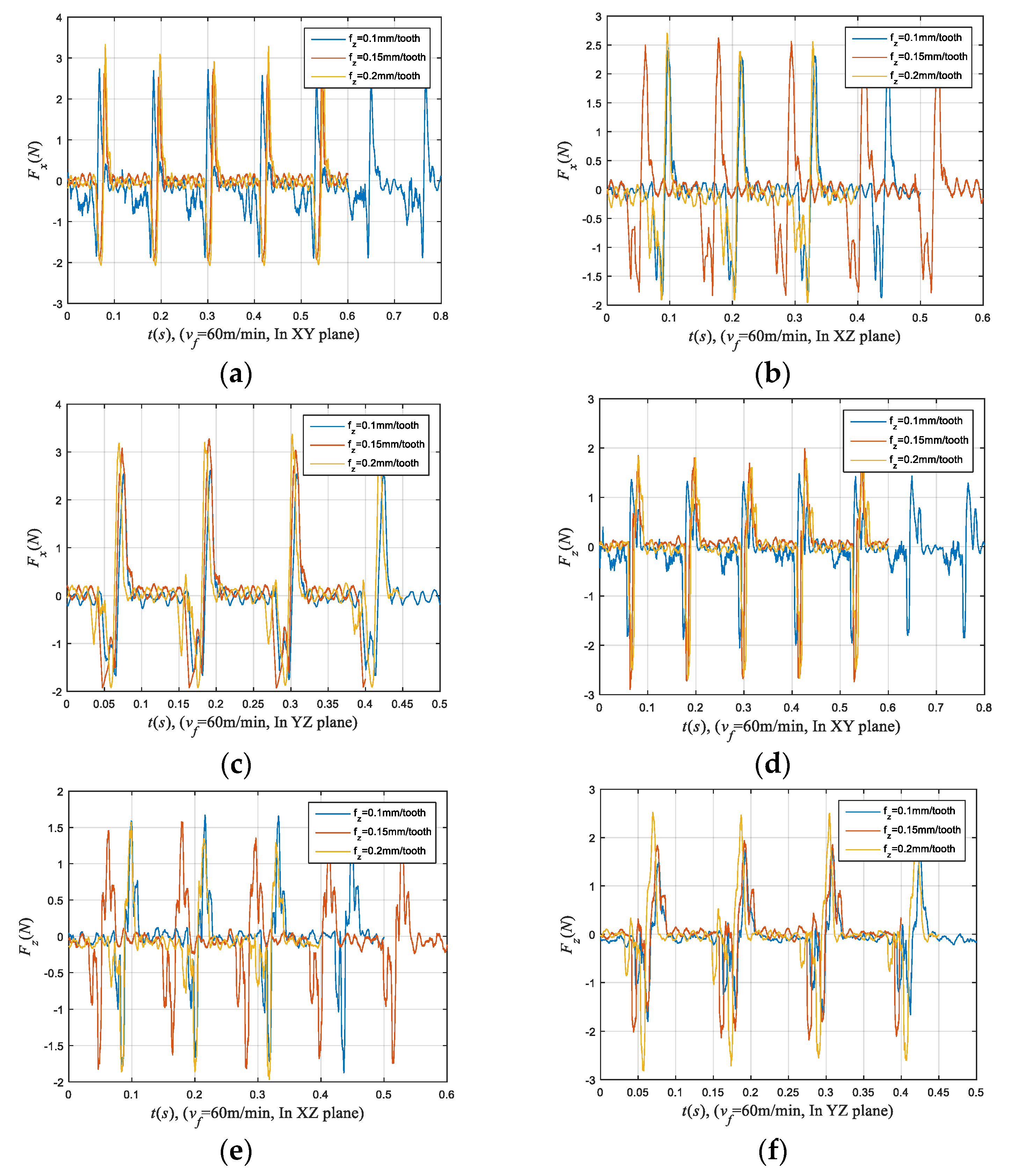
5.1. Effects on Cutting Forces

The force measurements included analyzing the force signals that were obtained using a three-axis force dynamometer while the workpiece traveled during finish milling experiment. The peak milling force in the stable stage of the cutting process is extracted to investigate the effect of cutting parameters, cutting direction, and scanning strategy on the resulting milling force. Henceforth, the peak values of the milling force at ten periods are extracted and then averaged. The averaged peak value is used in following analysis.

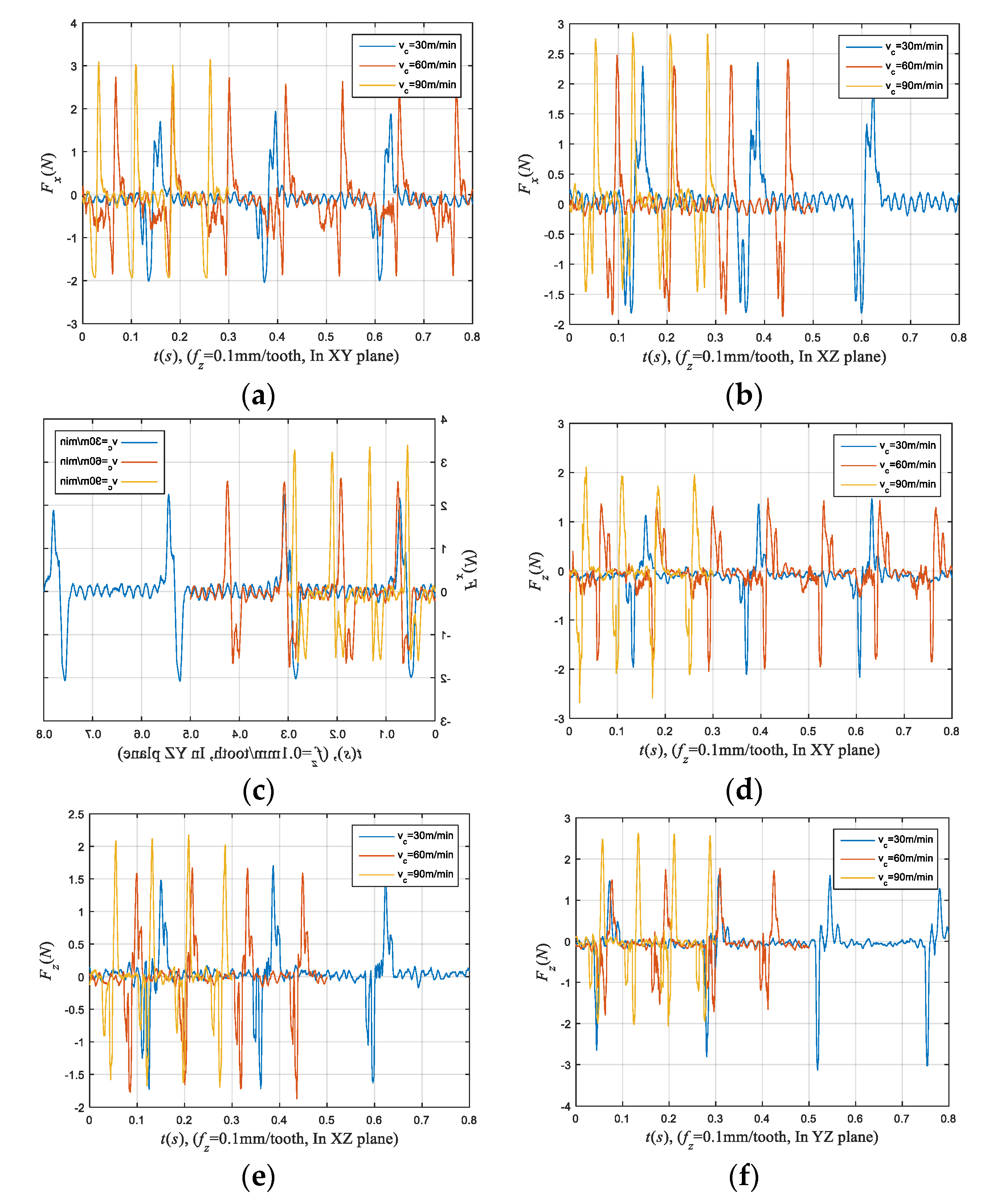
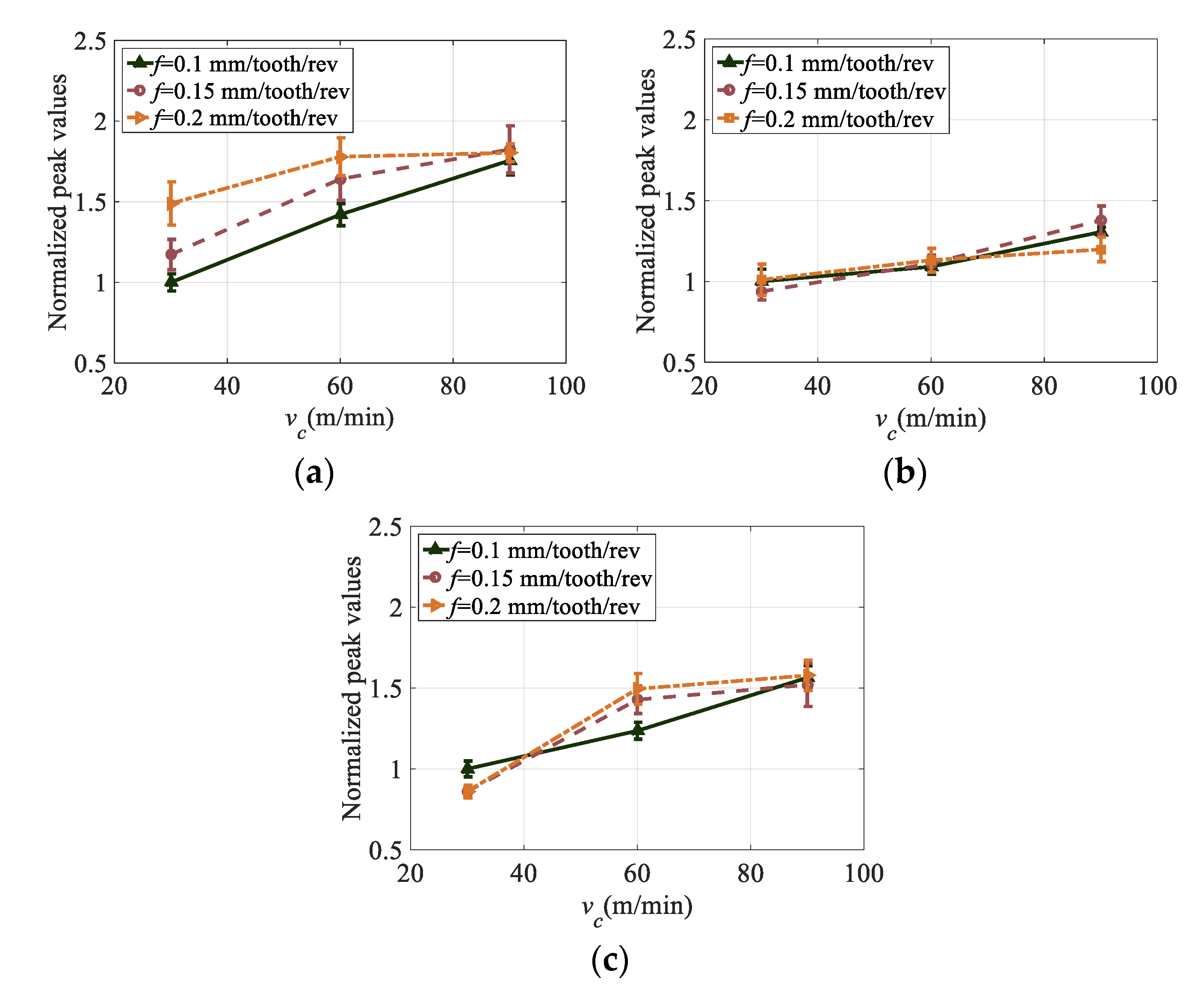
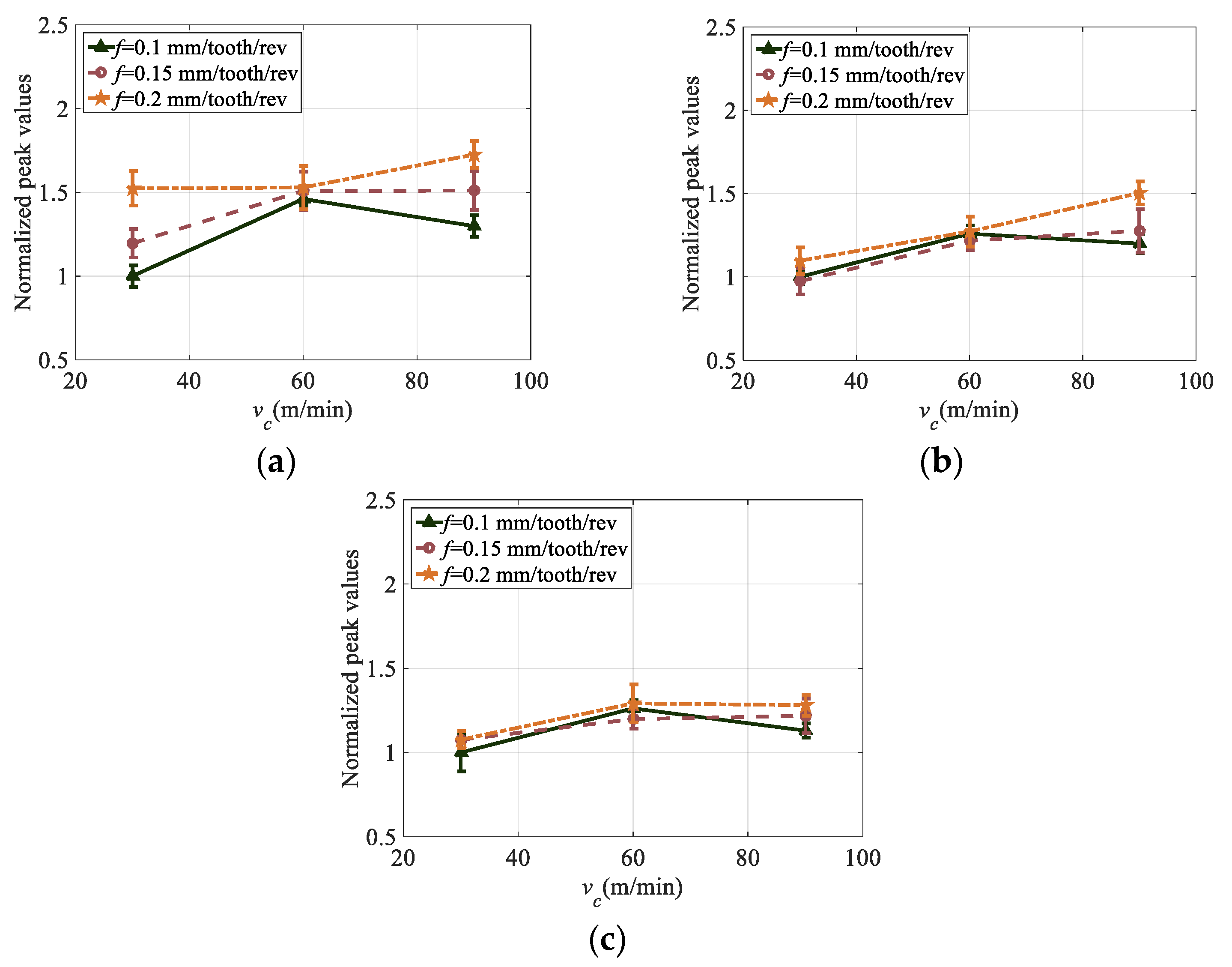
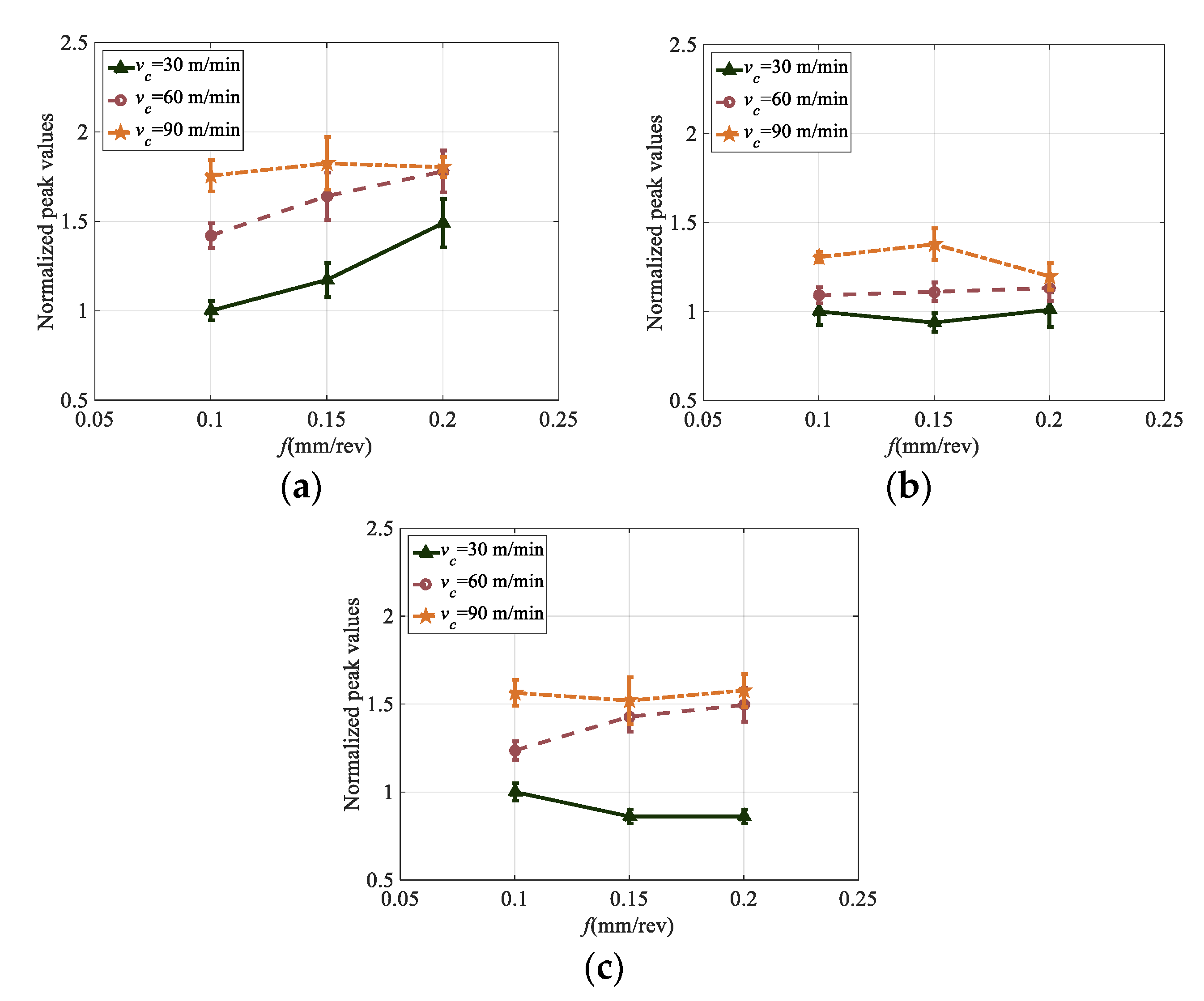
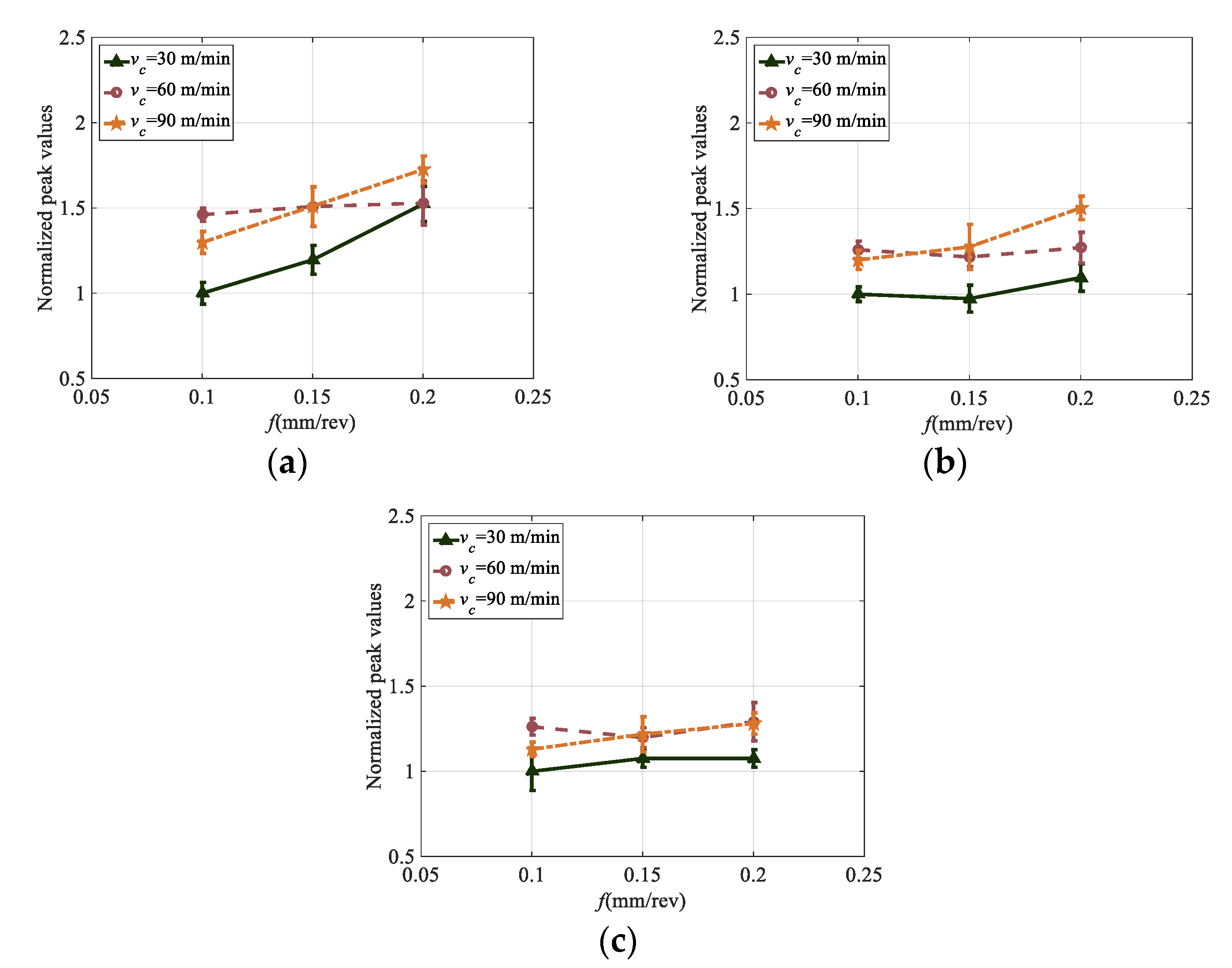
5.1.1. Effects of Cutting Speed and Feed Rate

The effect of cutting speed and feed rate on the milling forces (Fx and Fz) without normalization are shown in the force graphs as given in Figure 4 and Figure 5, respectively.
The averaged peak values of resultant milling force with respect to cutting speed are shown in Figure 6 and Figure 7 for finish milling of workpieces built with two different scan strategy rotations. Peak values of milling forces are normalized by dividing the resultant force to the force at the lowest cutting speed and feed rate at each case. For the workpiece built with SSR of 90°, the averaged peak cutting force increases with the increasing cutting speed, as can be seen from the Figure 6. For the workpiece built with the SSR of 67°, the peak milling force generally increases as the cutting speed increases from 30 m/min to 60 m/min, while it decreases as cutting speed increases from 60 m/min to 90 m/min at a feed rate 0.1 mm/tooth/rev, as shown in Figure 7.
The influence of feed rate on the peak milling force is shown in Figure 8 and Figure 9. It should be noted that based on the specifications obtained from the manufacturer of the L-PBF machine, the workpiece samples manufactured in Inconel 625 nickel-based alloy show different yield strength in different directions. The yield strength is higher in the cases 2 and 3 (see Figure 3) that is about 725 MPa. But it is lower in the case 1 along the build direction that is about 615 MPa [17]. Therefore, the cutting force is greater and increases when feed rate is increased in finish milling cases 2 and 3. That observations is not continually accurate since the difference in yield strength is more pronounce when cutting along the build direction [17]. Under some conditions, it is found that the peak milling force slightly decreases when the feed rate increases from 0.1 mm/tooth/rev to 0.15 mm/tooth/rev, and then increases when the feed rate increases from 0.15 mm/tooth/rev to 0.2 mm/tooth/rev for both types of workpieces.
Besides, peak milling force may increase at first and then decrease when the feed rate increases from 0.1 mm/tooth/rev to 0.2 mm/tooth/rev (vc = 90 m/min and milling in the XZ plane as shown in Figure 8b), or deceases when the feed rate increases from 0.1 mm/tooth/rev to 0.2 mm/tooth/rev (vc = 30 m/min and milling in YZ plane as shown in Figure 8c) for the workpiece built with the SSR of 90°.

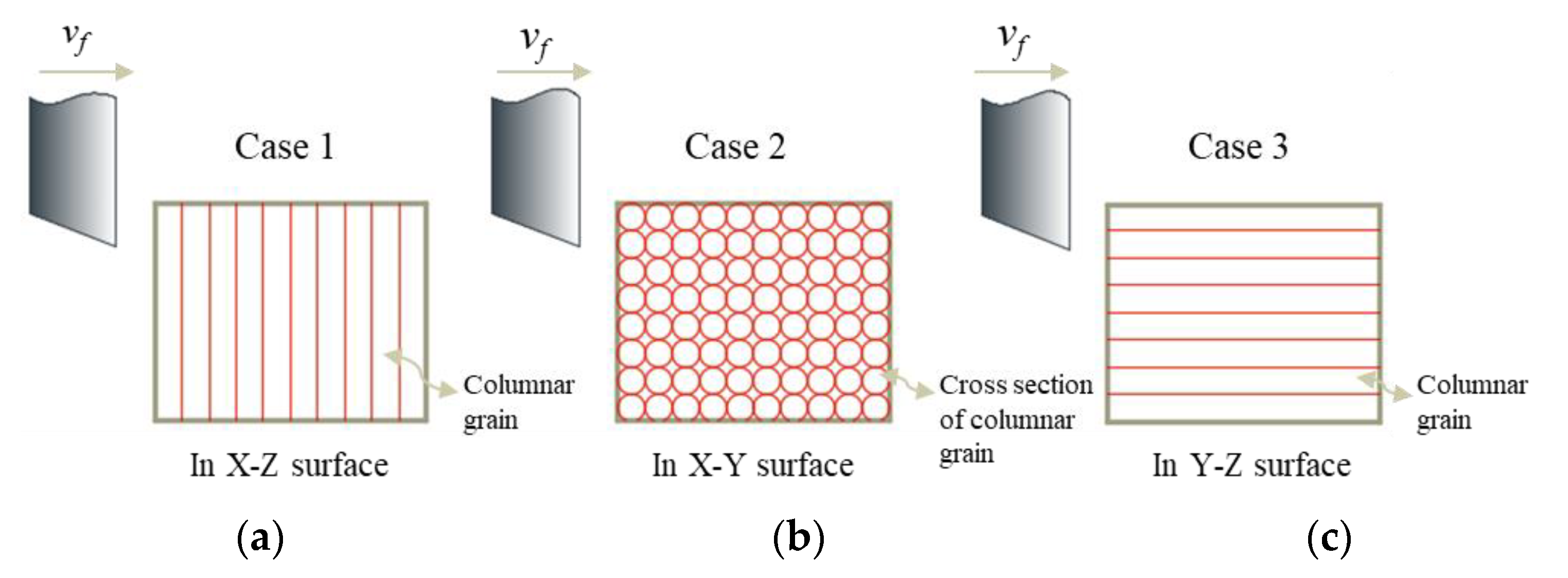
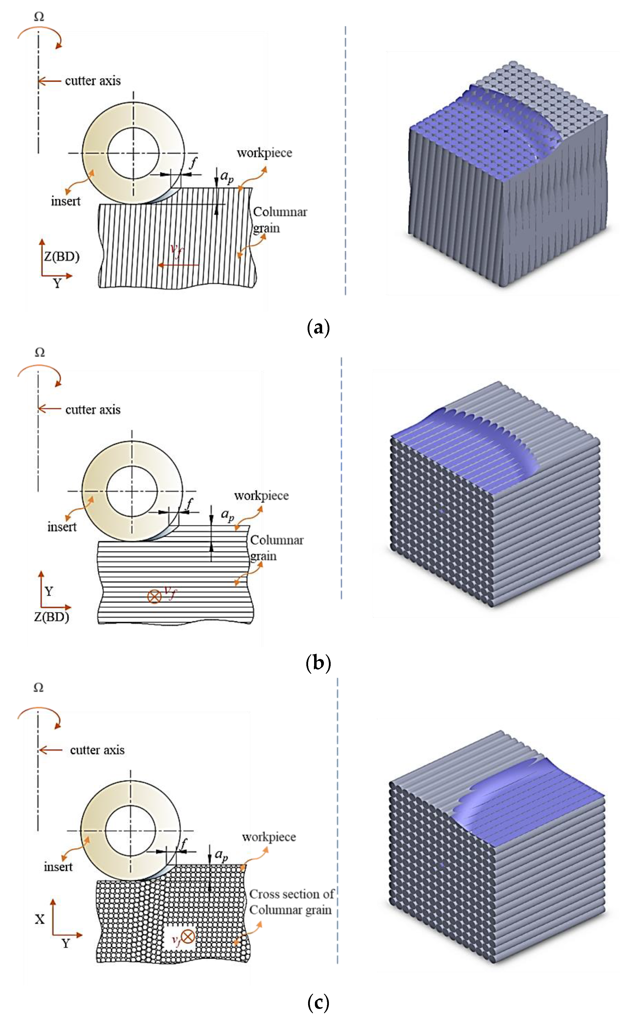
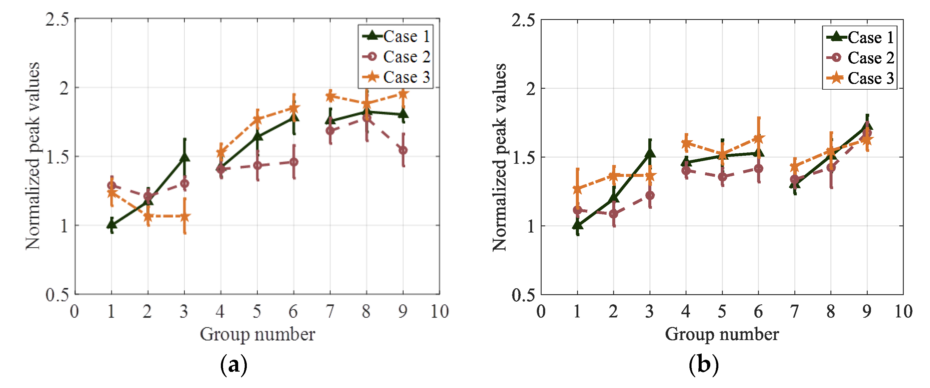
5.1.2. Effects of Cutting Direction

The averaged peak force with respect to different cutting direction is shown in Figure 10. Peak values of each workpiece are normalized by dividing the resultant force to the force at the lowest cutting speed and feed rate at each case 1. From the figure, it can be seen that peak milling forces are always larger for case 2 when compares to the ones for case 3 at a cutting speed of 30 m/min for workpiece that built with SSR of 90°. However, peak milling forces are always larger for case 3 when compares to the ones for case 2 when cutting speed is 30 m/min for workpiece that built with SSR of 67°. In general, the peak milling forces of case 3 have the largest values, followed by the peak milling forces of case 1, while the peak milling force of case 2 have the smallest values when cutting speeds are 60 m/min and 90 m/min for both workpieces.

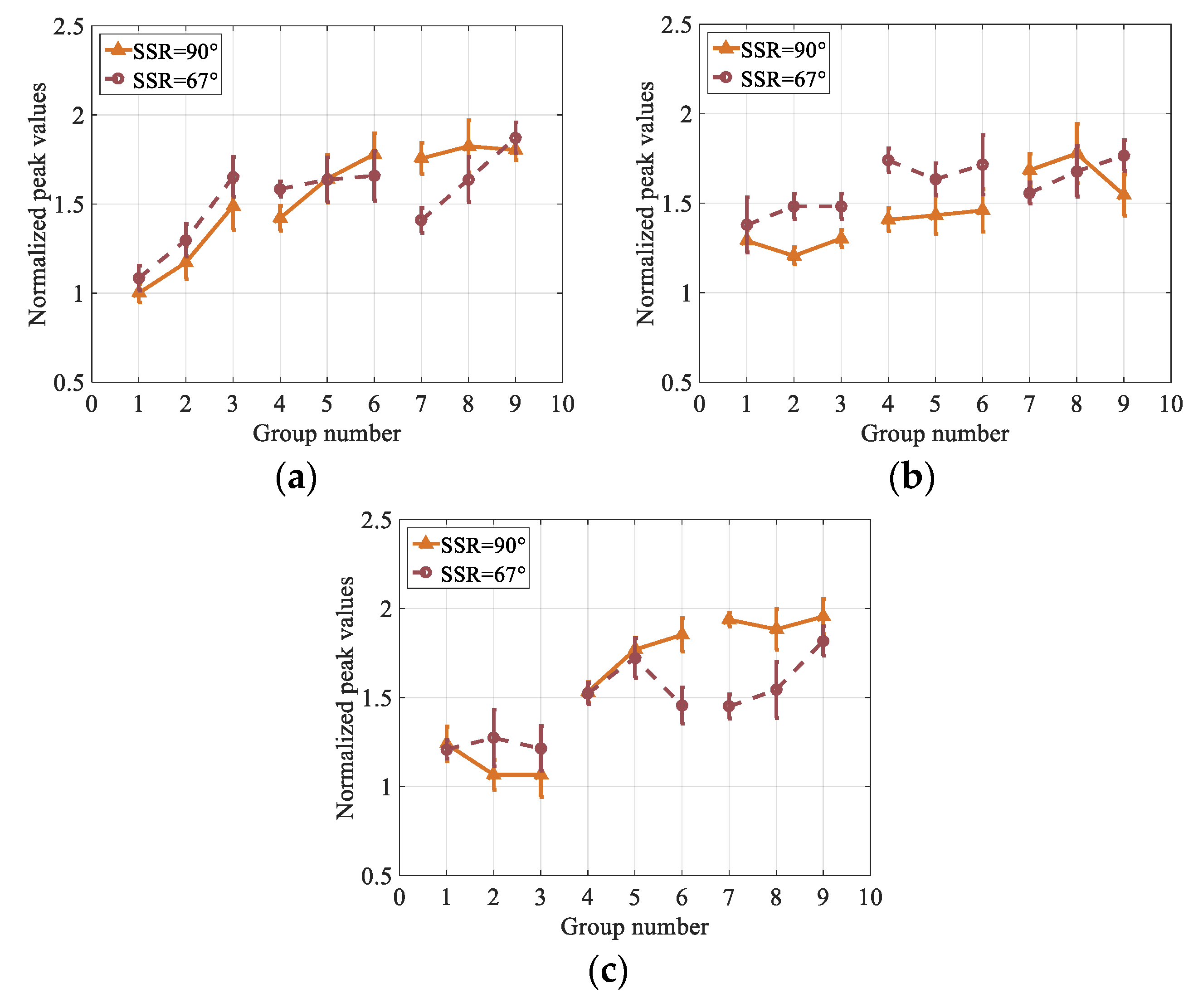
5.1.3. Effects of Scan Strategy Rotation

The averaged peak milling forces obtained by cutting two workpieces with different scan strategy rotation are compared, the comparison results are shown in Figure 11. All peak forces are normalized by dividing the one that obtained by the first group of cutting parameters of case 1 when milling the workpiece built with SSR of 90°.
An interesting result is that the cutting forces in finish milling of workpiece samples built with a scan strategy of SSR = 90° is lower than finish milling of samples built with SSR = 67° at the lowest cutting speed but this trend reverses at the highest cutting speed. The relative density of the workpiece samples built with the scan strategy of SSR = 90° are generally higher with less density variations but the samples built with the scan strategy of SSR = 67° is lower albeit with more variations. So, the porosity is not randomly distributed in the structure of the samples. Therefore, these force trends cannot be simply explained since the structure of the workpiece is complex. However, porosity induced by implementing scan strategy rotation seems effective in milling forces generated as it is evident from the trends in Figure 11.

5.2. Effects on Tool Wear

A rapid development of tool wear is always a problem during cutting heat resistant alloys due to rapid strain hardening, high strength even at elevated cutting temperatures, as well as poor thermal conductivity and chemical affinity with the tool materials [45]. Tool wear formation includes flank wear, crater wear, notch wear, and tool edge chipping in cutting nickel alloy Inconel 625 [46,47,48]. Different wear mechanisms will occur at different zones of the tool edge. One of the tool wear mechanism was edge chipping during milling of L-PBF manufactured nickel alloy Inconel 625 as shown Figure 12. Another wear mechanism of coating delamination and peeling was also observed. Other wear formations including flank wear, crater wear, notch wear, and built-up-edge were seldom observed. At some cutting conditions of low cutting speed and feed rate, the tool wear was not that significant as shown in Figure 13. In general, the fractured edge chipping is the main tool wear mechanism for all cutting conditions.

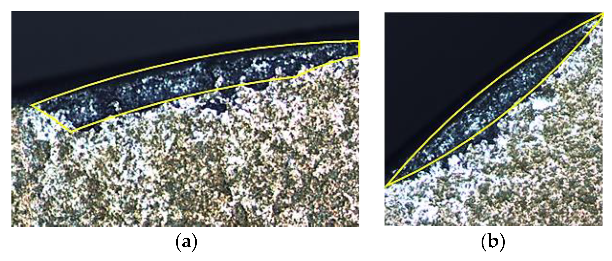
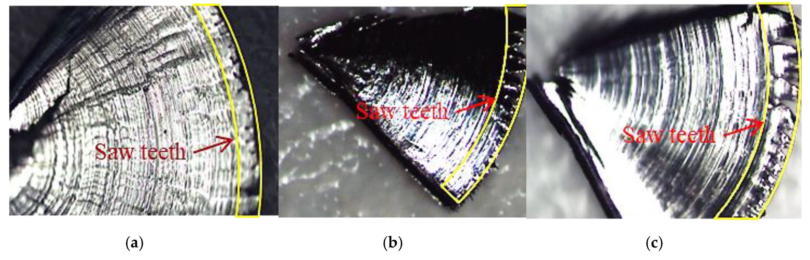
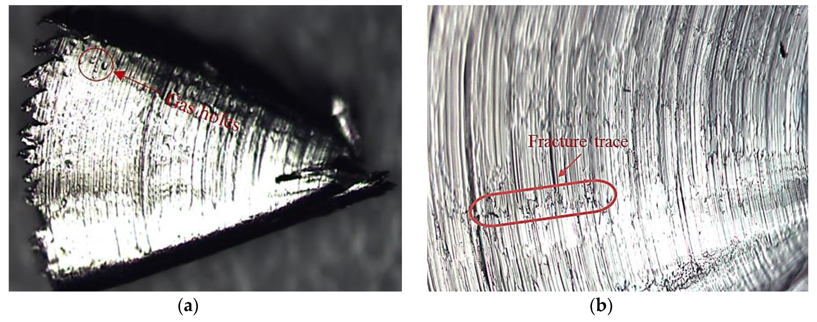
5.3. Effects on Chip Formation

It is observed that chips for all cutting experiments are discontinuous and slightly curled. Besides, almost all chips have a fan shape as shown in Figure 14. The saw-tooth type segmentation was observed at the outside end of the fan-shaped chip. The saw-tooth type segmentation occurs for all cutting conditions. The saw-tooth segments are not so sharp. Many of them are trapezoidal, instead of triangle in shape. The distance between adjacent saw-tooth segments in L-PBF manufactured Inconel 625 is very large, which is quite different from when machining SLM manufactured Ti64 [32]. There are cracks at the inner side of the fan-shaped chips as shown in the figure. The cracks are either along the radial direction or circumferential direction as shown in Figure 15. There are also some saw-tooth shaped edges at the inner side of the fan-shaped chips. Some flaws of the workpiece caused by L-PBF process such as air/gas porosity can be observed on the chip as well (shown in Figure 16).
The materials fracture trace can also be found on the chip surface that contacts with the rake face of the tool as shown in Figure 16. It seemed that cutting velocity and feed rate has little effect on the chip formation, which is different from the results obtained by Shunmugavel et al. [32]. Besides, the scanning strategy as well as the BD has little effect on the chip formation either.

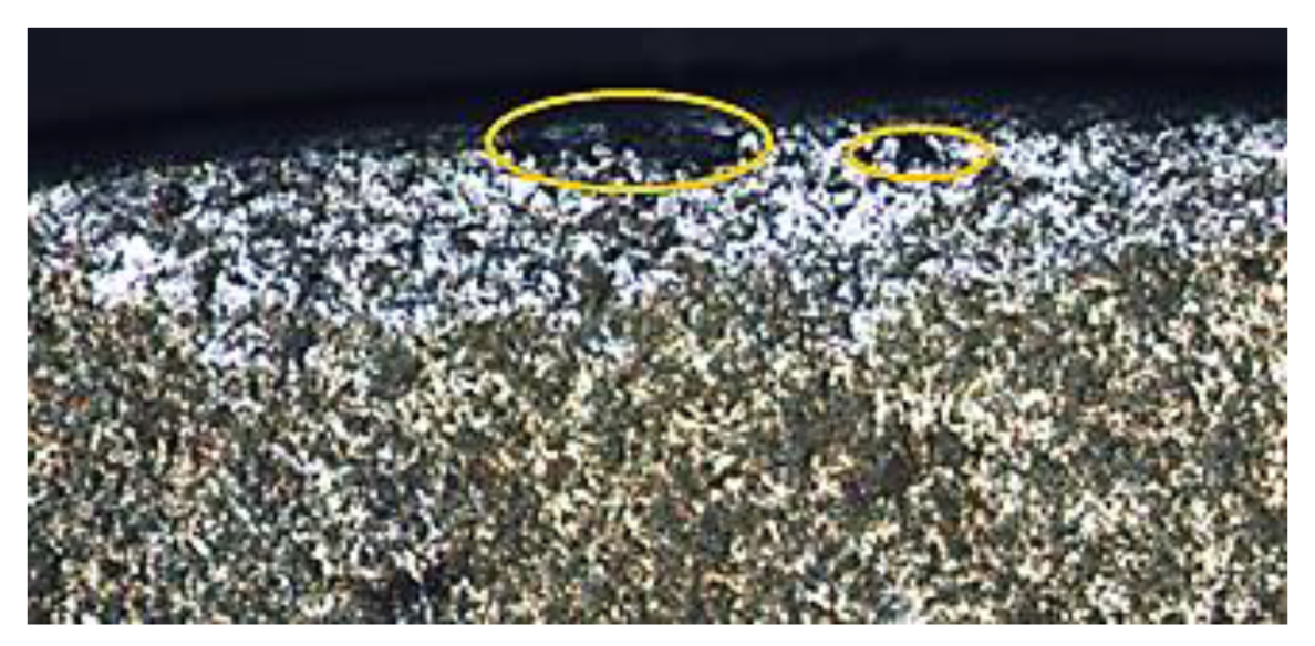
5.4. Effects on Surface Topography

After the workpiece is face milled, the machined surfaces were inspected under the optical microscopy. The feed marks of the machined surface can be clearly seen for all cutting conditions. The profiles of the feed marks are not so smooth, which is caused by the side flow of the materials. However, Bordin et al. [28] called these jagged feed marks peaks. The defects caused by some inappropriate L-PBF process effects can also be observed on the machined surface, especially the pores left in the workpiece due to gasification [49]. Under some milling conditions, the machined surface came out as pore-free or defect-free (as shown Figure 17a,b). Surface defects such as the smeared materials or adhered materials are rarely observed. However, some materials remain uncut can also be found around the feed mark profile (as shown Figure 17b), which severely deteriorates the surface quality.

6. Discussion

When finish milling the workpiece built with the SSR of 90°, the cutting forces increased with the increasing of cutting speed according to the experiment results, which agreed well with literature [22,23,25]. Fortunato et al. [22] attributed it to the tool wear. However, a new cutting edge is used for each cutting test during finish milling experiments, which indicates that tool wear is not the reason to cause higher cutting force at higher cutting speeds. The nickel-based alloy Inconel 625 has both strain hardening and strain rate hardening behavior. Therefore, the effect of strain rate hardening becomes dominant when finish machining at higher cutting speed (higher strain rates). Therefore, the cutting forces increase when the cutting speed is increased. Besides, the porosity may also have some effects according to Shunmugavel et al. [25].
The porosity caused by improper AM process parameters in the workpiece will result in micro impacts between the tool and the workpiece. When the cutting speed increases, the frequency of impacts increases thus the cutting forces increase. For the workpiece built with the SSR of 67°, the milling force increased with increasing cutting speed at feed rates of both 0.15 and 0.2 mm/tooth/rev. This can also be attributed to the strain rate hardening or the more frequently micro impacts caused by porosity at higher cutting speed. However, the milling force first increased and then decreased when the cutting speed increased from 30 to 90 m/min at a feed rate of 0.1 mm/tooth/rev. The milling force decreased at the higher cutting speed. The reason to cause this phenomenon is that the strain rate hardening is balanced by the thermal softening since increasing of cutting speed also leads to the increasing of cutting temperature during cutting, and thus the thermal softening of the workpiece. Consequently, cutting forces decrease. The increase of feed rate will increase the chip load and thus increase the cutting force since it can be written as F = K t a p h + K e a p according to Altintas [50], in which Kt and Ke are cutting coefficient and edge coefficient, respectively, h is cutting width, which is written as fz × sin (φ) where φ is immersion angle of the cutter tooth. This is true for cutting of additively manufactured steel [51] and the titanium alloy Ti64 [27]. However, the cutting forces did not always increase when the feed rate was increased in this investigation. This may be caused by the heterogeneous properties of the workpiece along the build direction caused by variation in the temperature gradient and cooling rate. From the bottom of the workpiece to its top (along the build direction), the hardness, the tensile stress, the yield strength, as well as the elongation will decrease gradually [52,53]. Besides, these parameters are also different in different locations at horizontal direction (perpendicular to the build direction) [52]. Therefore, the anisotropy of the workpiece makes that the milling forces do not always increase with the increasing feed rate. Shunmugavel et al. [21] investigated the effect of cutting direction on the cutting force from the microstructure level. They pointed out that when the cutting edge is perpendicular to the grain growth direction, the cutting forces has the highest value, followed by the case when the cutting edge moves along the columnar grain while the case when the cutting edge moves across the cross section of the columnar grain has the lowest cutting force. However, the relative location between the cutting edge and the grain direction is much more complex during finish milling since the cutting edge will move along a trochoid curve. Besides, the cutting edge is arched. The figures in Figure 3 are presented to illustrate the relative location between the cutting edge and the grain growth direction as well as the machined surface in this investigation. Left part of the figure is the relative location of the cutter edge and the columnar grains while the right part of the figure is the machined surface. The columnar grains of the workpiece were simplified as small cylinders in figure. It can be seen from the figure that the direction between the columnar grain and the cutter edge is quite different from the orthogonal cutting as shown in Figure 1. For case 1 and case 2, the cutter edge can be thought to move across the columnar grain while the cutter can be thought to move along the grain for case 3. Henceforth, milling forces under case 1 and case 2 should be larger than that under case 3. However, tested milling forces of case 3 have the highest values in this investigation. Fortunato et al. [22] attributed it to the material anisotropy, because the re-melt of the previous scanning tracks due to the proceeded scanning tracks, the re-melt of the previous several layers due to current layer, the unequal cooling rate, and the bond between two stripes will lead to the physical properties anisotropy of the L-PBF manufactured samples. The scanning strategy also affects the machinability through affecting the physical properties of the manufactured workpiece. According to Özel et al. [49], the manufactured workpiece has different microstructure including grain size and grain growth direction when different scanning strategy was used. The density of the workpieces used in this study with different scanning strategy is also slightly different. The density of the workpiece obtained with the SSR of 67° is smaller than that the SSR of 90° [42]. All these will make the cutting force different under the same cutting condition. The cutting force is larger when cutting the workpiece obtained by the SSR of 90°.
The chip is discontinuous because its three-dimensional chip load is shown Figure 18. This discontinuous chip load leads to the discontinuous chip. The chip load looks like a fan to some extent. That’s also why all the chips have fan shapes. The chips are slightly curled because of the trochoidal motion of the insert. There exists saw tooth at the two ends of the fan-shaped chips. So far, two predominant theories were developed to explain the saw-tooth chips [29,43]. They were: (i) thermoplastic instability and (ii) the initiation and propagation of the crack inside the primary shear zone of the workpiece materials. Thermoplastic instability theory attributes the saw tooth chip morphology to the competition between the thermal softening and the work hardening in the primary shear zone, while the theory of initiation and propagation of the crack tells that the saw tooth is caused by the crack initiation and propagation. However, both theories cannot be used to explain the saw tooth observed at the two ends of the fan-shaped chips.
The tensile stress in the chip can be thought to be along the radial direction or along the circumferential direction as shown in Figure 19. The circumferential stress continues to increase toward the radial direction on the fan shaped chip. The tensile stress at the edges of the chip is large enough to rip the outer edge and hence form the serration or saw-tooth like appearance. On the contrary, toward the inner side of the fan shaped chip is more compressive and squeeze the inner edge of the chip. The crack along the radial direction also follows this explanation. Besides, the initiation crack in the chip may also lead to the saw tooth chip.
Mainly edge chipping is observed during milling the L-PBF built nickel alloy Inconel 625. Usually, chipping of the tool is caused by the high hardness of the tool. Besides, lack of tool edge strength, lack of shank and tool holder rigidity as well as high feed rate will also lead to the tool chipping. The inserts used in this investigation is carbide, instead of ceramic. Thus, the edge chipping is possibly caused by the lack of shank and the tool holder rigidity since a long shank is used during milling. The use of only one insert may also have some impact. Since one insert will lead to dynamic unbalance and thus make the tool have large vibration amplitude. Besides, at the instant when the insert contacts the workpiece, the insert will impact with the workpiece and thus lead to vibro-impact. This may also lead to edge chipping. Under some cutting conditions with small cutting speed and feed rate, the tool wear is not that significant. This is understandable because lower load occurs under these cutting conditions and thus less tool wear forms.
The surface defects are direct results of the cutting process; they cannot be eliminated but reduced by choosing proper cutting parameters. In this investigation, surface defects such as smeared or adhered materials were founded, as well as the side flow materials. The adhered or smeared materials occurred because of the left particles welded on the surface or BUE. The side flow materials were found along the feed marks. The material side flow is caused by the plastic deformation of the surface material due to the tool vibration, which enhanced by an increased plasticity caused by the higher cutting temperatures during milling. The jagged feed marks peaks were observed almost for all cutting conditions. It is caused by low plasticity of the alloy.

7. Conclusions

In this paper, the machinability of the laser powder bed fusion manufactured nickel alloy Inconel 625 is investigated. The effect of cutting parameters including cutting velocity and feed rate, the cutting direction, and scanning strategy of the L-PBF process on the cutting force, tool wear, chip morphology as well as surface finish are discussed. The experimental results are analyzed in detail. The main highlight of these findings is that the additively manufactured Inconel 625 metal workpieces show significantly unique behavior on the effect of build direction and scanning strategy on the machinability aspect of the finish milling process that reveals a need for essential process planning for finish machining operations.
Some of specific conclusions can be drawn from the result of cutting experiments can be listed as follows:
(i)
The milling force will generally increase with the cutting speed;
(ii)
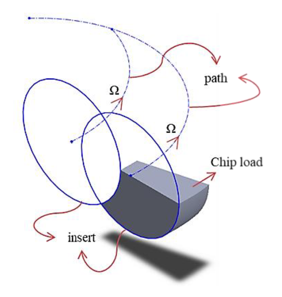
The milling force will generally increase with the feed rate because of the increasing of the chip load;
(iii)
Cutting along the BD or normal to the BD will have influence on the milling force. The AM manufactured workpiece physical properties, microstructure is BD dependent. Henceforth, the machinability of the final workpiece also BD dependent and thus the milling force along or normal to the BD is very different. However, it is difficult to tell the discipline;
(iv)
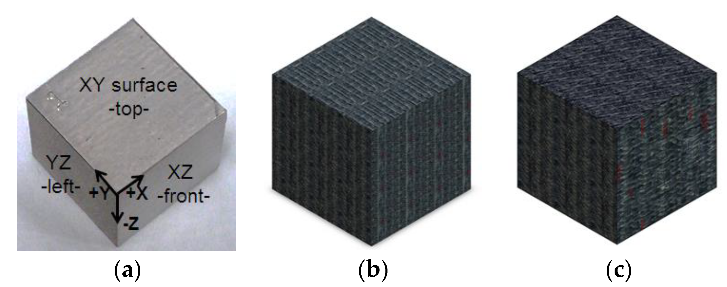
The scanning strategy will affect the milling force because it has effect on the physical parameters such as the density, the microstructure of the additively manufactured workpiece. The milling force is always bigger when cutting the cubic sample obtained with SRR = 90°;
(v)
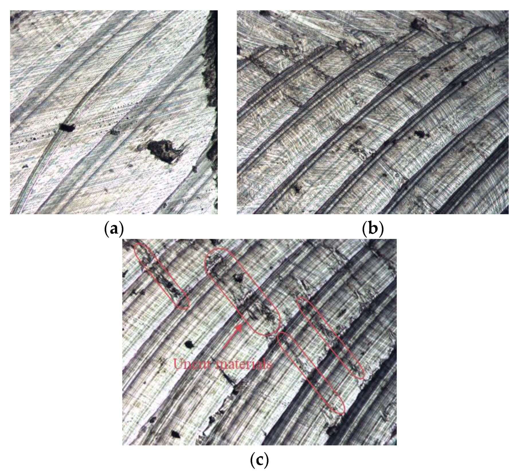
The shapes of the chips are regularly fan-shaped with saw-tooth formation along the outer and inner chip edges;
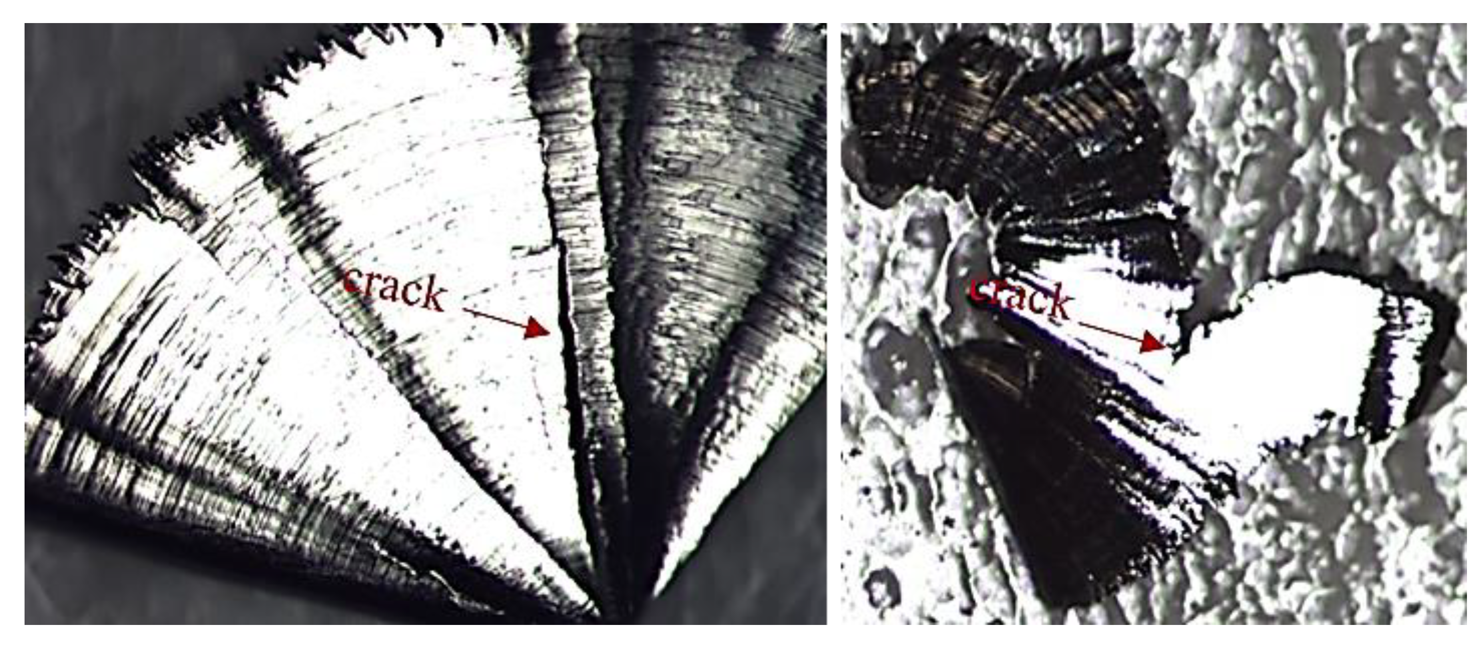
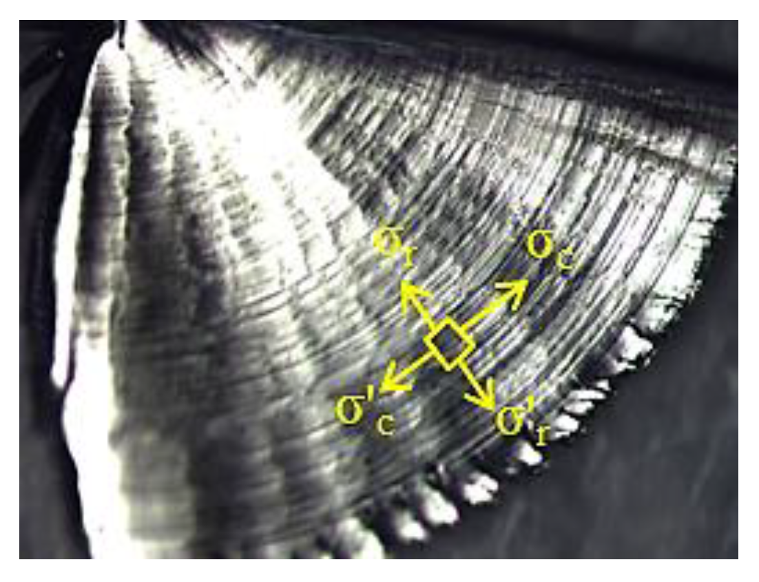
(vi)
Due to compressive stress build-up along the edges of the chips, there exists some cracks mostly along the radial direction and some along the circumferential direction;
(vii)
The main tool wear of the inserts is edge chipping, coat peeling is also observed;
(viii)
Side flow materials, jagged feed mark peaks as well as adhered and smeared materials are observed on the machined surface.
It should be pointed out that the physics of the phenomena in milling additively manufactured non-homogeneous structured nickel alloy Inconel 625 reported in this paper should be further investigated by using finite element simulations (predicting cutting force effects, tool wear, chip formation and shapes) in future research studies.

Author Contributions

Conceptualization, T.Ö.; methodology, J.F., G.L., K.P., and T.Ö.; software and validation, J.F., G.L. and T.Ö.; formal analysis and investigation, J.F., G.L., K.P., and T.Ö.; data curation, K.P.; writing—original draft preparation, J.F. and G.L.; writing—review and editing, T.Ö.; visualization, J.F., G.L., and T.Ö.; supervision, T.Ö.; project administration, T.Ö.; funding acquisition, T.Ö. All authors have read and agreed to the published version of the manuscript.

Funding

The sample fabrication was funded by National Institute of Standards and Technology through financial assistance number 70NANB14H227. J. Fei and G. Liu were funded by the China Scholarship Council.

Conflicts of Interest

The authors declare no conflict of interest.

References

  1. Ulutan, D.; Özel, T. Machining induced surface integrity in titanium and nickel alloys: A review. Int. J. Mach. Tools Manuf. 2011, 51, 250–280. [Google Scholar] [CrossRef]
  2. Thakur, A.; Gangopadhyay, S. State-of-the-art in surface integrity in machining of nickel-based superalloys. Int. J. Mach. Tools Manuf. 2016, 100, 25–54. [Google Scholar] [CrossRef]
  3. Ezugwu, E.O.; Bonney, J.; Yamane, Y. An overview of the machinability of aero engine alloys. J. Mater. Process. Technol. 2003, 135, 233–253. [Google Scholar] [CrossRef]
  4. M’Saoubi, R.; Axinte, D.; Soo, S.L.; Nobel, C.; Attia, H.; Kappmeyer, G.; Engin, S.; Sim, W.M. High performance cutting of advanced aerospace alloys and composite materials. CIRP Ann. Manuf. Technol. 2015, 64, 557–580. [Google Scholar] [CrossRef]
  5. Hällgren, S.; Pejryd, L.; Ekengren, J. Additive manufacturing and high speed machining—cost comparison of short lead time manufacturing methods. Procedia Cirp 2016, 50, 384–389. [Google Scholar] [CrossRef] [Green Version]
  6. Piili, H.; Happonen, A.; Väistöc, T.; Venkataramanan, V.; Partanen, J.; Salminen, A. Cost estimation of laser additive manufacturing of stainless steel. Phys. Procedia 2015, 78, 388–396. [Google Scholar] [CrossRef]
  7. Kaynak, Y.; Tascioglu, E. Finish machining-induced surface roughness, microhardness and XRD analysis of selective laser melted Inconel 718 alloy. Procedia Cirp 2018, 71, 500–504. [Google Scholar] [CrossRef]
  8. Brown, D.; Li, C.; Liu, Z.Y.; Fang, X.Y.; Guo, Y.B. Surface integrity of Inconel 718 by hybrid selective laser melting and milling. J. Virtual Phys. Prototyp. 2018, 13, 26–31. [Google Scholar] [CrossRef]
  9. Calleja, A.; Urbikain, G.; González, H.; Cerrillo, I.; Polvorosa, R.; Lamikiz, A. Inconel®718 superalloy machinability evaluation after laser cladding additive manufacturing process. Int. J. Adv. Manuf. Technol. 2018, 97, 2873–2885. [Google Scholar] [CrossRef]
  10. Kim, D.; Park, E.; Kim, N.; Park, H. Experimental investigation on tool wear during the milling processes for the post-processing of selective laser melted Inconel 718 alloys. In Proceedings of the ASME International Manufacturing Science and Engineering Conference, MSEC2018-6561, 2018, V001T01A011, College Station, TX, USA, 18–22 June 2018. [Google Scholar]
  11. Guo, J.; Au, K.H.; Sun, C.N.; Goh, M.H.; Kum, C.W.; Liu, K.; Kang, R. Novel rotating-vibrating magnetic abrasive polishing method for double-layered internal surface finishing. J. Mater. Process. Technol. 2019, 264, 422–437. [Google Scholar] [CrossRef]
  12. Li, D.; Guo, Q.; Guo, S.; Peng, H.; Wu, Z. The microstructure evolution and nucleation mechanisms of dynamic recrystallization in hot-deformed Inconel 625 superalloy. Mater. Des. 2011, 32, 696–705. [Google Scholar] [CrossRef]
  13. Das, S.; Wohlert, M.; Beaman, J.J.; Bourell, D.L. Producing metal parts with selective laser sintering/hot isostatic pressing. JOM 1998, 50, 17–20. [Google Scholar] [CrossRef]
  14. Murr, L.E. Metallurgy of additive manufacturing: Examples from electron beam melting. Addit. Manuf. 2015, 5, 40–53. [Google Scholar] [CrossRef] [Green Version]
  15. Arısoy, Y.M.; Criales, L.E.; Özel, T.; Lane, B.; Moylan, S.; Donmez, A. Influence of scan strategy and process parameters on microstructure and its optimization in additively manufactured nickel alloy 625 via laser powder bed fusion. Int. J. Adv. Manuf. Technol. 2016, 90, 1393–1417. [Google Scholar] [CrossRef]
  16. EOS GmbH Electro Optical Systems. EOS Titanium Ti64 Material Data Sheet. 2020. Available online: http://www.rpplusm.com/assets/eos_titanium_ti64_en-(1).pdf (accessed on 1 April 2020).
  17. EOS GmbH Electro Optical Systems. EOS Nickel alloy Inconel 625 Material Data Sheet. 2020. Available online: https://dmlstechnology.com/images/files/MATERIALS_EOS_NickelAlloy_IN625.pdf (accessed on 1 April 2020).
  18. Shunmugavel, M.; Polishetty, A.; Nomani, J.; Goldberg, M.; Littlefair, G. Metallurgical and Machinability Characteristics of Wrought and Selective Laser Melted Ti-6Al-4V. J. Metall. 2016, 7407918. [Google Scholar] [CrossRef] [Green Version]
  19. Deng, D.; Peng, R.L.; Brodin, H.; Moverare, J. Microstructure and mechanical properties of Inconel 718 produced by selective laser melting: Sample orientation dependence and effects of post heat treatments. Mater. Sci. Eng. A 2018, 713, 294–306. [Google Scholar] [CrossRef]
  20. Arısoy, Y.M.; Guo, C.; Kaftanoğlu, B.; Özel, T. Investigations on microstructural changes in machining of Inconel 100 alloy using face turning experiments and 3D finite element simulations. Int. J. Mech. Sci. 2016, 107, 80–92. [Google Scholar] [CrossRef] [Green Version]
  21. Shunmugavel, M.; Polishetty, A.; Goldberg, M.; Nomani, J.; Littlefair, G. Influence of build orientation on machinability of selective laser melted titanium alloy-Ti-6Al-4V, World Academy of Science, Engineering and Technology. Int. J. Chem. Mol. Nucl. Mater. Metall. Eng. 2017, 11, 515–519. [Google Scholar]
  22. Fortunato, A.; Lulaj, A.; Melkote, S.; Liverani, E.; Ascari, A.; Umbrello, D. Milling of maraging steel components produced by selective laser melting. Int. J. Adv. Manuf. Technol. 2018, 94, 1895–1902. [Google Scholar] [CrossRef]
  23. Guo, P.; Zou, B.; Huang, C.; Gao, H. Study on microstructure, mechanical properties and machinability of efficiently additive manufactured AISI 316L stainless steel by high-power direct laser deposition. J. Mater. Process. Technol. 2017, 240, 12–22. [Google Scholar] [CrossRef]
  24. Le Coz, G.; Fischer, M.; Piquard, R.; D’Acunto, A.; Laheurte, P.; Dudzinski, D. Micro Cutting of Ti-6Al-4V Parts Produced by SLM Process. Procedia Cirp 2017, 58, 228–232. [Google Scholar] [CrossRef]
  25. Shunmugavel, M.; Polishetty, A.; Goldberg, M.; Singh, R.; Littlefair, G. A comparative study of mechanical properties and machinability of wrought and additive manufactured (selective laser melting) titanium alloy Ti-6Al-4V. Rapid Prototyp. J. 2017, 23, 1051–1056. [Google Scholar] [CrossRef]
  26. Imbrogno, S.; Bordin, A.; Bruschi, S.; Umbrello, D. Experimental analysis on semi-finishing machining of Ti6Al4V additively manufactured by direct melting laser sintering. AIP Conf. Proc. 2016, 1769, 080007. [Google Scholar]
  27. Oyelola, O.; Crawforth, P.; M’Saoubi, R.; Clare, A.T. On the machinability of directed energy deposited Ti6Al4V. Addit. Manuf. 2018, 19, 39–50. [Google Scholar] [CrossRef]
  28. Bordin, A.; Bruschi, S.; Ghiotti, A.; Bariani, P.F. Analysis of tool wear in cryogenic machining of additive manufactured Ti6Al4V alloy. Wear 2015, 328, 89–99. [Google Scholar] [CrossRef]
  29. Bordin, A.; Sartori, S.; Bruschi, S.; Ghiotti, A. Experimental investigation on the feasibility of dry and cryogenic machining as sustainable strategies when turning Ti6Al4V produced by Additive Manufacturing. J. Clean. Prod. 2017, 142, 4142–4151. [Google Scholar] [CrossRef]
  30. Shunmugavel, M.; Polishetty, A.; Goldberg, M.; Singh, R.; Littlefair, G. Tool Wear and Surface Integrity Analysis of Machined Heat Treated Selective Laser Melted Ti-6Al-4V. Int. J. Mater. Form. Mach. Process. 2016, 3, 50–63. [Google Scholar] [CrossRef] [Green Version]
  31. Sartori, S.; Moro, L.; Ghiotti, A.; Bruschi, S. On the tool wear mechanisms in dry and cryogenic turning Additive Manufactured titanium alloys. Tribol. Int. 2017, 105, 264–273. [Google Scholar] [CrossRef]
  32. Shunmugavel, M.; Goldberg, M.; Polishetty, A.; Nomani, J.; Sun, S.; Littlefair, G. Chip formation characteristics of selective laser melted Ti–6Al–4V. Aust. J. Mech. Eng. 2017, 17, 109–126. [Google Scholar] [CrossRef]
  33. Oyelola, O.; Crawforth, P.; M’Saoubi, R.; Clare, A.T. Machining of Additively Manufactured Parts: Implications for Surface Integrity. Procedia Cirp 2016, 45, 119–122. [Google Scholar] [CrossRef]
  34. Polishetty, A.; Shunmugavel, M.; Goldberg, M.; Littlefair, G.; Singh, R.K. Cutting Force and Surface Finish Analysis of Machining Additive Manufactured Titanium Alloy Ti-6Al-4V. Procedia Manuf. 2017, 7, 284–289. [Google Scholar] [CrossRef] [Green Version]
  35. Huang, X.; Bai, Q.; Li, Y.T.; Zhang, B. Machining Finish of Titanium Alloy Prepared by Additive Manufacturing. In Applied Mechanics and Materials; Trans Tech Publication: Zurich, Switzerland, 2017; pp. 43–48. [Google Scholar]
  36. Rotella, G.; Imbrogno, S.; Candamano, S.; Umbrello, D. Surface Integrity of machined additively manufactured Ti alloys. J. Mater. Process. Technol. 2018, 259, 180–185. [Google Scholar] [CrossRef]
  37. Sartori, S.; Bordin, A.; Ghiotti, A.; Bruschi, S. Analysis of the Surface Integrity in Cryogenic Turning of Ti6Al4V Produced by Direct Melting Laser Sintering. Procedia Cirp 2016, 45, 123–126. [Google Scholar] [CrossRef]
  38. Bruschi, S.; Bertolini, R.; Bordin, A.; Medea, F.; Ghiotti, A. Influence of the machining parameters and cooling strategies on the wear behavior of wrought and additive manufactured Ti6Al4V for biomedical applications. Tribol. Int. 2016, 102, 133–142. [Google Scholar] [CrossRef]
  39. Li, S.; Wei, Q.; Shi, Y.; Zhu, Z.; Zhang, D. Microstructure Characteristics of Inconel 625 Superalloy Manufactured by Selective Laser Melting. J. Mater. Sci. Technol. 2015, 31, 946–952. [Google Scholar] [CrossRef]
  40. Fei, J.; Liu, G.; Patel, K.; Özel, T. Cutting force investigation in face milling of additively fabricated nickel alloy 625 via powder bed fusion. Int. J. Mechatron. Manuf. Syst. 2019, 12, 196–210. [Google Scholar] [CrossRef]
  41. Patel, K.; Fei, J.; Liu, G.; Özel, T. Milling investigations and yield strength calculations for nickel alloy Inconel 625 manufactured with laser powder bed fusion process. Prod. Eng. 2019, 13, 693–702. [Google Scholar] [CrossRef]
  42. Criales, L.E.; Arısoy, Y.M.; Lane, B.; Moylan, S.; Donmez, A.; Özel, T. Laser powder bed fusion of nickel alloy 625: Experimental investigations of effects of process parameters on melt pool size and shape with spatter analysis. Int. J. Mach. Tools Manuf. 2017, 121, 22–36. [Google Scholar] [CrossRef]
  43. Murr, L.E.; Gaytan, S.M.; Ramirez, D.A.; Martinez, E.; Hernandez, J.; Amato, K.N.; Shindo, P.W.; Medina, F.R.; Wicker, R.B. Metal Fabrication by Additive Manufacturing Using Laser and Electron Beam Melting Technologies. J. Mater. Sci. Technol. 2012, 28, 1–14. [Google Scholar] [CrossRef]
  44. Kechagias, J.D.; Nikolaos, K.-E.A.; Fountas, A.; Vaxevanidis, N.M.; Manolakos, D.E. A comparative investigation of Taguchi and full factorial design for machinability prediction in turning of a titanium alloy. Measurement 2020, 151, 107213. [Google Scholar] [CrossRef]
  45. Parida, A.K.; Maity, K. Comparison the machinability of Inconel 718, Inconel 625 and Monel 400 in hot turning operation. Eng. Sci. Technol. Int. J. 2018, 21, 364–370. [Google Scholar] [CrossRef]
  46. Lotfi, M.; Jahanbakhsh, M.; Akhavan Farid, A. Wear estimation of ceramic and coated carbide tools in turning of Inconel 625: 3D FE analysis. Tribol. Int. 2016, 99, 107–116. [Google Scholar] [CrossRef]
  47. Lotfi, M.; Ashrafi, H.; Amini, S.; Akhavan Farid, A.; Jahanbakhsh, M. Characterization of various coatings on wear suppression in turning of Inconel 625: A three-dimensional numerical simulation. Proc. Inst. Mech. Eng. Part J J. Eng. Tribol. 2016, 231, 734–744. [Google Scholar] [CrossRef]
  48. Jahanbakhsh, M.; Akhavan Farid, A.; Lotfi, M. Optimal flank wear in turning of Inconel 625 super-alloy using ceramic tool. Proc. Inst. Mech. Eng. Part B J. Eng. Manuf. 2016, 232, 208–216. [Google Scholar] [CrossRef]
  49. Özel, T.; Altay, A.; Donmez, A.; Leach, R. Surface topography investigations on nickel alloy 625 fabricated via laser powder bed fusion. Int. J. Adv. Manuf. Technol. 2018, 94, 4451–4458. [Google Scholar] [CrossRef]
  50. Altintas, Y. Manufacturing Automation: Metal Cutting Mechanics, Machine Tool Vibrations, and CNC Design, 2nd ed.; Cambridge University Press: Cambridge, UK, 2012. [Google Scholar]
  51. Montevecchi, F.; Grossi, N.; Takagi, H.; Scippa, A.; Sasahara, H.; Campatelli, G. Cutting Forces Analysis in Additive Manufactured AISI H13 Alloy. Procedia Cirp 2016, 46, 476–479. [Google Scholar] [CrossRef] [Green Version]
  52. Wang, J.F.; Sun, Q.J.; Wang, H.; Liu, J.P.; Feng, J.C. Effect of location on microstructure and mechanical properties of additive layer manufactured Inconel 625 using gas tungsten arc welding. Mater. Sci. Eng. A 2016, 676, 395–405. [Google Scholar] [CrossRef]
  53. Xu, F.; Lv, Y.; Liu, Y.; Shu, F.; He, P.; Xu, B. Microstructural Evolution and Mechanical Properties of Inconel 625 Alloy during Pulsed Plasma Arc Deposition Process. J. Mater. Sci. Technol. 2013, 29, 480–488. [Google Scholar] [CrossRef]
Figure 1. Illustration of relative direction between the cutting velocity and the columnar grain growth direction along build direction; (a) Case 1, (b) Case 2, and (c) Case 3.
Jmmp 04 00032 g001
Figure 2. Faces and surfaces of the nickel alloy Inconel 625 workpiece (a) and illustration of directionality in 90° (b) and 67° (c) scan strategy rotation on the workpiece.
Jmmp 04 00032 g002
Figure 3. The relative orientation of milling insert to the build direction (BD) (left) and the illustration of the machined surface (right): (a) case 1: cutting against columnar grains; (b) case 2: cutting along columnar grains in horizontal direction; (c) case 3: cutting along the columnar grains in vertical direction.
Jmmp 04 00032 g003
Figure 4. The influence of cutting speed on milling forces in Fx without normalization: (a) Case 1 (milling in XY plane), (b) Case 2 (milling in XZ plane), (c) Case 3 (milling in YZ plane) and milling forces in Fz without normalization: (d) Case 1, (e) Case 2, (f) Case 3 for the workpiece built with SSR of 90°.
Jmmp 04 00032 g004
Figure 5. The influence of feed rate on milling forces in Fx without normalization: (a) Case 1 (milling in XY plane), (b) Case 2 (milling in XZ plane), (c) Case 3 (milling in YZ plane) and milling forces in Fz without normalization: (d) Case 1, (e) Case 2, (f) Case 3 for the workpiece built with SSR of 90°.
Jmmp 04 00032 g005
Figure 6. The influence of cutting speed on milling forces: (a) Case 1 (milling in XY plane), (b) Case 2 (milling in XZ plane), (c) Case 3 (milling in YZ plane) for the workpiece built with SSR of 90°.
Jmmp 04 00032 g006
Figure 7. The influence of cutting speed on milling forces: (a) Case 1 (milling in XY plane), (b) Case 2 (milling in XZ plane), (c) Case 3 (milling in YZ plane) for the workpiece built with SSR of 67°.
Jmmp 04 00032 g007
Figure 8. The influence of feed rate on milling forces: (a) Case 1 (milling in XY plane), (b) Case 2 (milling in XZ plane), (c) Case 3 (milling in YZ plane) for the workpiece built with the SSR of 90°.
Jmmp 04 00032 g008
Figure 9. The influence of feed rate on milling forces: (a) Case 1 (milling in XY plane), (b) Case 2 (milling in XZ plane), (c) Case 3 (milling in YZ plane) for the workpiece built with the SSR of 67°.
Jmmp 04 00032 g009
Figure 10. The influence of the cutting direction on the milling forces for the two workpieces: (a) the workpiece built with the SSR of 90°, (b) the workpiece built with the SSR of 67°.
Jmmp 04 00032 g010
Figure 11. Milling forces comparison between two scan strategies: (a) Case 1 (milling in XY plane), (b) Case 2 (milling in XZ plane), (c) Case 3 (milling in YZ plane).
Jmmp 04 00032 g011
Figure 12. The tool chipping observed during finish milling of the workpiece built with the SSR of 67° under different cutting conditions: (a) vc = 90 m/min, f = 0.1 mm/tooth/rev when milling in the XY plane, (b) vc = 90 m/min, f = 0.2 mm/tooth/rev when milling in the XY plane.
Jmmp 04 00032 g012
Figure 13. Slight tool wear observed when finish milling the workpiece built with the SSR of 67° with vc = 30 m/min, f = 0.1 mm/tooth/rev when milling in the XZ plane.
Jmmp 04 00032 g013
Figure 14. Chip morphology during finish milling of L-PBF manufactured Inconel 625 under different cutting conditions: (a) vc = 90 m/min, f = 0.1 mm/tooth/rev in the XY plane, (b) vc = 30 m/min, f = 0.2 mm/tooth/rev in the XY plane, (c) vc = 30 m/min, f = 0.15 mm/tooth/rev in the XY plane when milling the workpiece built with the SSR of 90°.
Jmmp 04 00032 g014
Figure 15. Cracks observed on the additively manufactured nickel alloy Inconel 625 chips.
Jmmp 04 00032 g015
Figure 16. Defects on the chip morphology (a) air/gas pores on the chip surface and (b) fracture trace.
Jmmp 04 00032 g016
Figure 17. Surface irregularities (a) partially defect-free, (b) partially pore-free, (c) smeared and adhered uncut material that are observed on the machined surfaces of additively manufactured alloy Inconel 625.
Jmmp 04 00032 g017
Figure 18. The three dimensional (3D) chip load in finish milling with a round insert.
Jmmp 04 00032 g018
Figure 19. Illustration of stress state on the fan shaped nickel alloy Inconel 625 chip.
Jmmp 04 00032 g019
Table 1. Cutting parameters used in finish milling experiments.
Test NumberΩ (rpm)vc (m/min)f (mm/rev)vf (mm/min)
1636.6300.163.7
2636.6300.1595.5
3636.6300.2127.3
41273600.1127.3
51273600.15191
61273600.2254.6
71910900.1191
81910900.15286.5
91910900.2382

