Article

Multi-Wire Sawing of Translucent Alumina Ceramics

1
Fraunhofer ISE, Am St. Niclas-Schacht 13, 09599 Freiberg, Germany
2
Fraunhofer IKTS, Winterbergstr. 28, 01277 Dresden, Germany
3
TU Bergakademie Freiberg, Agricolastr. 17, 09599 Freiberg, Germany
4
Smart Material GmbH, Löbtauerstr. 69, 01159 Dresden, Germany
*
Author to whom correspondence should be addressed.
J. Manuf. Mater. Process. 2020, 4(1), 2; https://doi.org/10.3390/jmmp4010002
Submission received: 17 December 2019 / Revised: 8 January 2020 / Accepted: 9 January 2020 / Published: 11 January 2020

Abstract

:
Multi-wire sawing has emerged as the leading technology in wafer production for a variety of semiconductor materials. This study investigates the process stability and efficiency of conventional semiconductor multi-wire slurry saws in routinely machining translucent, high-density alumina ceramics. The brittle and fine-grained translucent alumina ceramics with extreme hardness and wear resistance represents a major challenge for the process. The alumina ceramic substrates are used for sensor applications, energy storage technology and applications in power electronics. An ideal adaptation of the sawing process parameters to the workpiece properties guarantees the efficiency of the slurry sawing process and the quality of the ceramic wafers. An indicator of the efficiency and cutting ability of the sawing process is the size of the bow of the wire web. The first time was shown that the wire bow can be used for the characterization of the sawing processes for hard and brittle technical ceramics. It was found that a longer workpiece length, a higher number of wafers and stronger abrasive wear lead to an increased size of the bow. The rocking frequency has no measurable influence on the size of the bow. Knowledge of these relations is an extremely valuable tool in the sawing process development for hard and brittle technical ceramics.

1. Introduction

Multi-wire sawing allows cutting of hard and brittle materials with high throughput at potentially low costs. The alumina ceramic substrates are used for sensor applications, energy storage technology and applications in power electronics. Wire sawing of alumina ceramics or sapphire with fixed abrasive grain (diamond wire sawing) is described in the literature [1,2]. The sawing technology with loose abrasive grain (slurry sawing) has proven to be beneficial for multi-wire sawing of hard and brittle materials compared to diamond wire sawing because the material removal mechanism is more efficient [3,4]. Ceramic blocks with extreme hardness and a fine-grained structure can be cut into thin discs (0.15–2 mm). With optimized sawing process parameters, the production of thin ceramic wafers with minimal thickness variations and uniform roughness values can be made reliable. Various authors have investigated the removal mechanism of multi-wire slurry sawing in recent decades [4,5,6,7,8]. Most of the models that describe the multi-wire sawing process with loose abrasive grain have been developed based on the rolling-indenting model. This model, in which the rolling abrasive grains press into the workpiece surface, causing chipping, was originally developed for the lapping of glasses. It states that only 5–10% of the largest abrasive particles are involved in the removal process [5,6]. In order to apply the rolling-indenting model to the multi-wire sawing process, the fracture mechanics of the brittle material, the behavior of the wire and the slurry must account for the whole cutting process. A material removal model for the wire sawing process was developed by Möller et al. [7]. The relevant approaches of the model for this work are presented below. The removal volume V 0 by one particle indentation is calculated as follows:
V 0 = π · α 0.5 · β * 2 2 · t a n ρ · H 0.5 F N ( 4 n + 1 ) / 2 .
Parameter α is an indenter-geometry factor and β * a factor that depends on E, H and KIC of the workpiece and 2 dimensionless factors [µm/Nn]. The half-angle of the indenting grain is ρ , H is the hardness of the workpiece, FN the normal force acting upon the abrasive particle and n is an empirical factor. From the chipping volume caused by a single indentation event, the material removal rate v s (thickness of a layer removed per unit of time) along the sawing channel can be calculated as a function of the wire speed using the following formula:
v s = v s 0 · v · m · F N ( 4 n + 1 ) / 2 .
The parameter v is the wire speed and m the number of indentation events. The parameter v s 0 is described with the following expression:
v s 0 = π · α 0.5 · β * 2 4 · t a n ρ · H 0.5 · A s · L 0 .
As is the contact area in the sawing channel for the indentation events and L0 the distance between the wire and the workpiece. The material removal rate is indirectly proportional to the size of the contact area, the hardness of the workpiece and the distance between wire and workpiece. In this study, the influence of various workpiece geometry and process parameters on the cutting ability is correlated to the material removal rate.

2. Materials and Methods

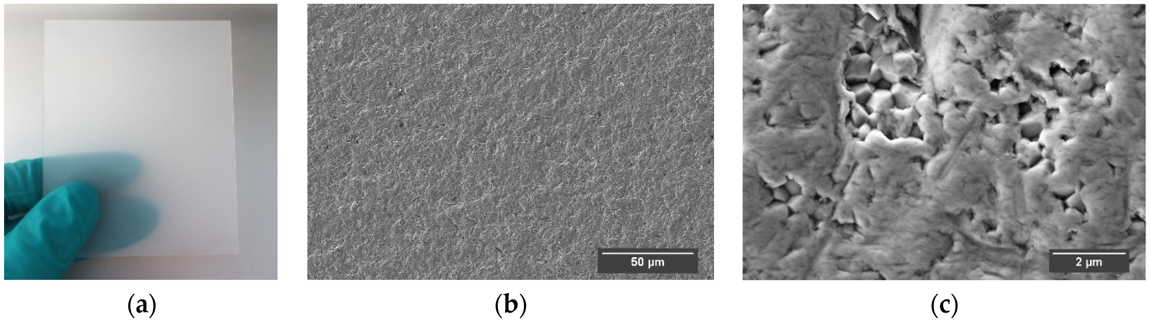
2.1. Used Ceramic Material

All multi-wire sawing experiments were performed on a high-density, translucent alumina ceramic. The microstructure of the alumina ceramic can be seen in Figure 1. The alumina ceramic material was brought to the required dimensions for the multi-wire sawing experiments with the band saw BS270F from DRAMET.
In Table 1 the properties of the used alumina ceramic are listed.
The mechanical characterization of the alumina ceramic included the measurement of the density by the Archimedes method, the hardness (H) by Vickers indentation tests and the elastic modulus (E), determined with the acoustic impulse excitation. The grain size was analyzed using the linear intercept method (300 grains were measured). The fracture toughness (KIC) was assessed by the 4-point bending single edge V-notched beam method. The bending strength was determined with the 4-point bending test on bars of the dimensions 3 mm × 4 mm × 50 mm with a distance of 20 mm between the supports and a loading velocity of 0.5 mm/min. In a first feasibility study it could be demonstrated that it is possible to cut the alumina ceramic with extreme hardness and wear resistance in thin discs using the sawing technology with loose abrasive grain (Figure 2).

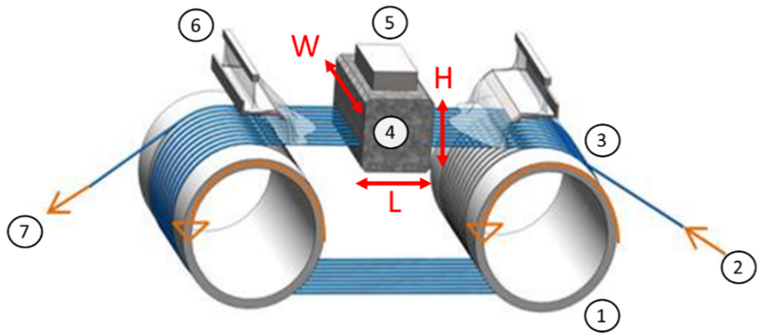
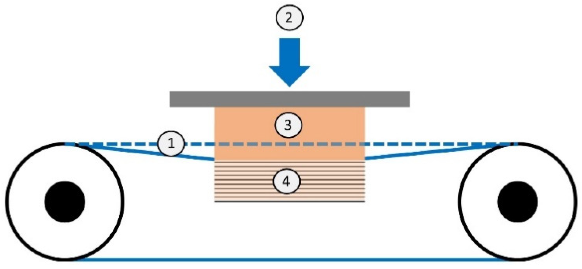
2.2. Multi-Wire Sawing

All experiments were conducted on a multi-wire saw type DS265 from Meyer and Burger (Thun, Switzerland). A schematic drawing of a multi-wire slurry saw from Meyer and Burger (Thun, Switzerland) is shown in Figure 3. The used type of multi-wire saw consists of two wire guide rollers and a web of wires spanned in between. The horizontal distance of the wire guide rollers is 660 mm (between the axes). The wire tension holds the wire in the wire guide grooves and dampens the vibration of the wire during the sawing process. The distance between the wires in the wire guide grooves defines the thickness of the wafers. The workpiece is glued to a beam, which is attached to the feed table. The rotation of the wire guide rollers accelerates the wire as the feed table presses the workpiece onto the wire web. From the slurry nozzles, a mixture of polyethylene glycol and abrasive particles is applied on the wire field. About 50% by mass of abrasive particles are contained in this mixture. The mixture adheres to the wires, is carried along by the wire speed and is fed into the workpiece. The forced movement of the abrasive particles in the sawing channel causes chipping of the material. The sawing channel, which is constantly deepened by the material removal, leads to separate wafers at the end of a sawing process [9].

2.3. Experimental Procedure

If the wire is in contact with the workpiece and the cutting speed is lower than the feed speed, a bow of the wire web will form under the workpiece (Figure 4). The size of the bow is an indicator for the cutting ability under the chosen conditions. The smaller the bow, the better the cutting ability. In this study, the influence of various sawing parameters and workpiece geometries on the size of the bow was tested. Therefore, alumina ceramic blocks with a height of 30 mm and variable width and length were pressed on the wire web for cutting. After a feed length of 25 mm, the process is stopped, and the workpiece is moved out of the wire web. A feed length of 25 mm is needed to guarantee a constant material removal rate with a stable size of the bow. The length of the repositioning movement of the workpiece against the feed direction, until the wire web is smoothed (measuring error: ±50 µm) represents the bow of the wire web. The systematic analysis of the size of the wire bow provides a novel concept for monitoring the multi-wire sawing process of hard and brittle ceramics.
For all sawing processes, a standard wire (structured steel wire; coating: copper, zinc; nominal diameter: 115 µm) for multi-wire slurry sawing was used. The thickness of the wire needs to be adapted to the groove width of the wire guide rollers and the size of the abrasive particles used to avoid wire breakage. The periodical curvatures in 2 dimensions increase the effective wire diameter (Figure 5). The periodical curvatures of the wire allow for a larger amount of slurry to be transported into the sawing channel compared to a conventional straight steel wire [11]. This enables sawing at higher feed rates. In the sawing process, the wire bow elongates the structured wire and thus increases the wire tension locally under the workpiece. The result is a loss of wire tension due to plastic deformation when the wire leaves the workpiece [12].
In this study boron-carbide grains with the size F-400 are used as cutting agent in the loose abrasive slurry. The specification F-400 characterizes a normal distribution of the particle size from 8–32 µm around the d50 value of 22.5 µm. Scanning-electron microscopy (used device: JSM-6610 JEOL, Tokyo, Japan) was used to visualize the shape of the grains. The abrasive particle size and distribution were measured with the LS 13 320 Laser Diffraction Particle Size Analyzer from Beckman Coulter (Brea, CA, USA). All sawing parameters of the standard sawing recipe are listed in Table 2.
Due to the mechanical properties of the used alumina ceramic, the workpiece can only be cut with a table feed rate of 20 µm/min. When multi-wire sawing of silicon, feed rates > 700 µm/min are possible [8].
In experiment I, the workpiece lengths of 37.5; 75 and 150 mm were sawn, and the size of the bow was measured after each process. In experiment II, the influence of the workpiece width on the size of the bow was investigated (constant workpiece length: 75 mm). The workpiece width determines the number of wafers cut in one process. The bow of the wire web was analyzed when cutting 17, 34 and 51 wafers with a constant pitch of 0.425 mm. This corresponds to a workpiece width of 8; 16 and 32 mm. In experiment III, the sawing process parameter of the rocking frequency was varied to visualize differences in the cutting ability. The frequencies of 0.083; 0.25; 0.38 and 0.5 Hz were implemented into the standard sawing recipe (workpiece length: 75 mm; number of wafers: 17). The surface roughness and thickness of the ceramic wafers cut in experiment I, II and III were characterized by an optical profilometer (FRT MicroProf R).

3. Results and Discussion

In this chapter the influence of the workpiece length, the number of wafers and the rocking frequency, as well as the wear of the abrasive particles on the size of the bow, is analyzed.

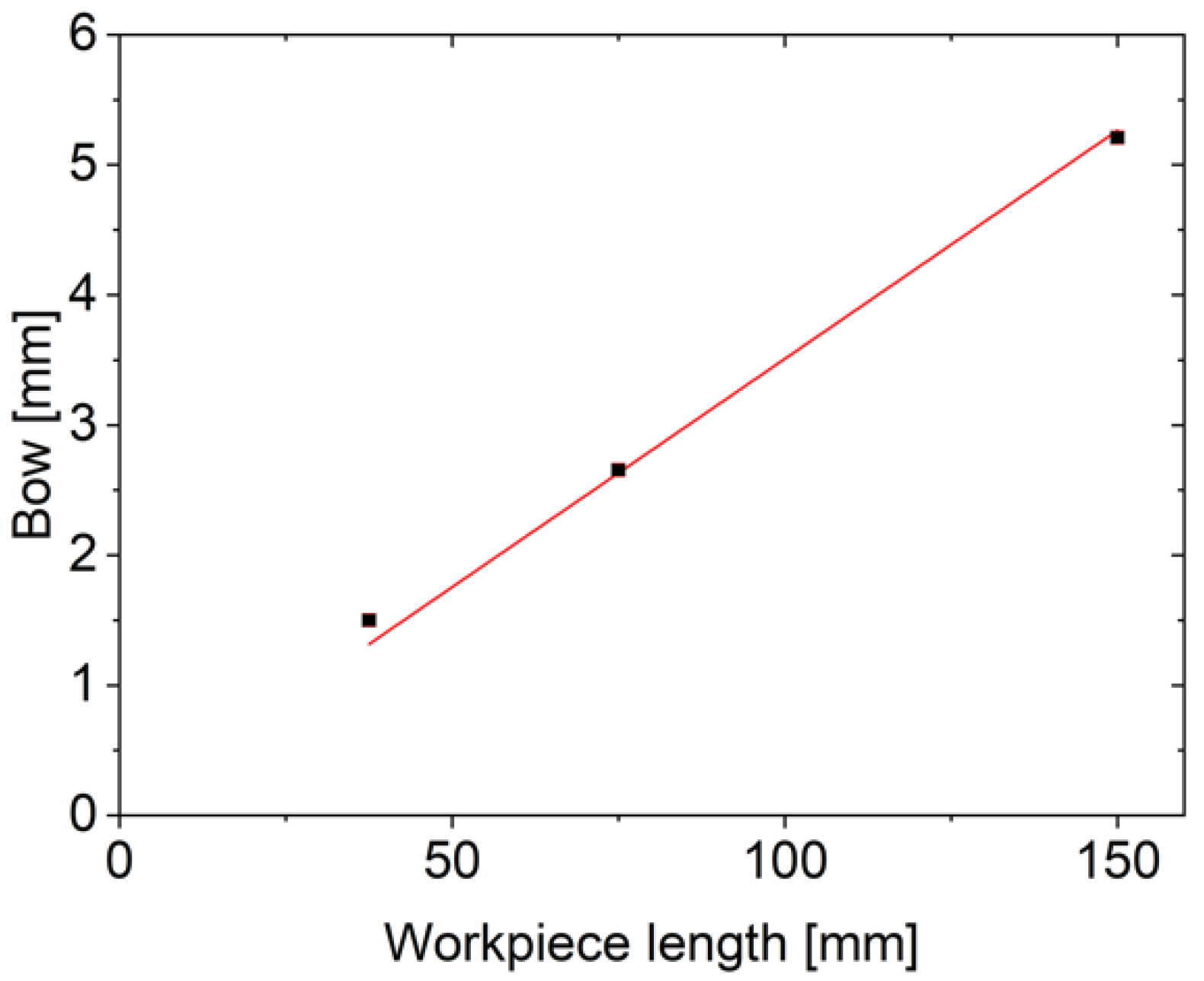
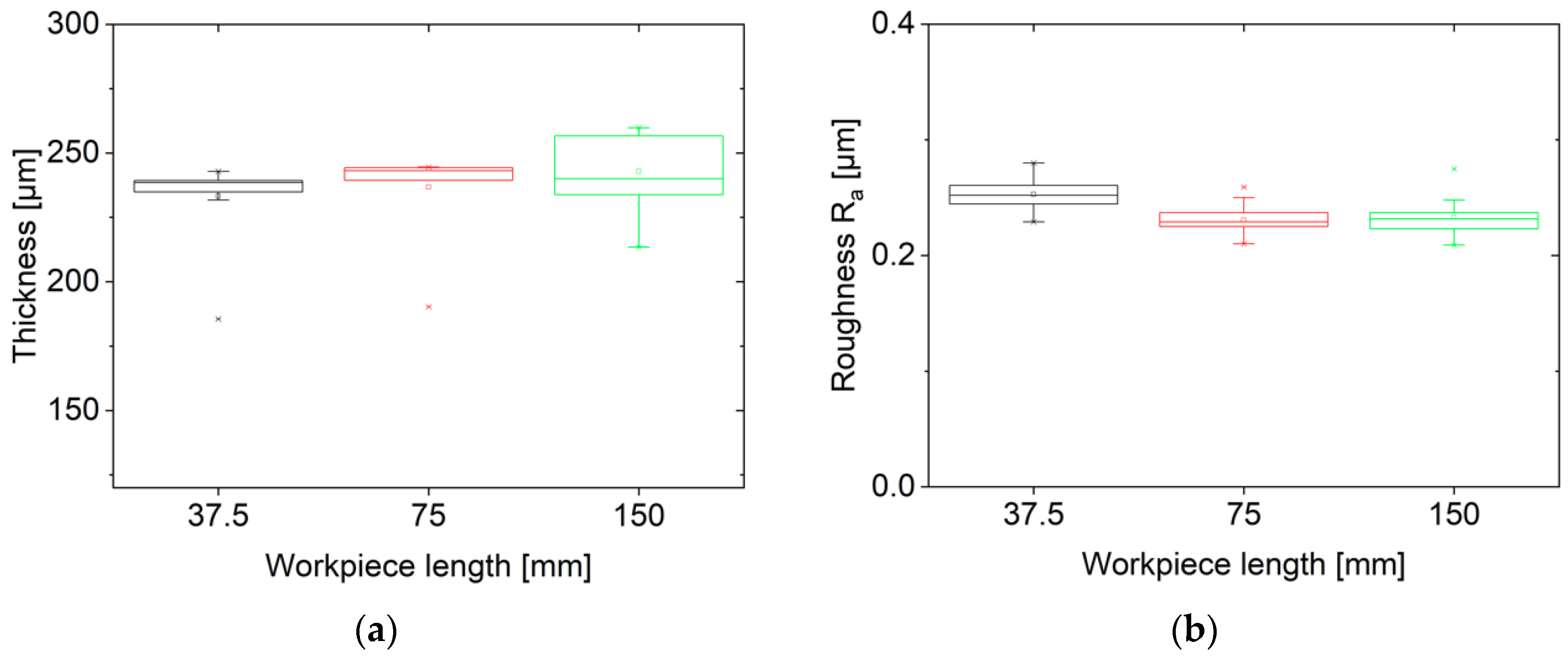
3.1. Variation of the Workpiece Length

The variation of the workpiece length shows a strong influence on the size of the bow of the wire web. The doubling of the workpiece length results in a doubling of the bow. A linear relationship between the size of the bow and the workpiece length could be identified.
Figure 6 shows an increasing size of the bow by 0.035 (±1 × 10⁻³) mm per mm workpiece length in the investigated range of 37.5–150 mm workpiece length. This observation is consistent with Equation (3) from the model of Möller et al. [7], where an increasing contact area As per wire in the sawing channel is indirectly proportional to the material removal rate. The reduced material removal rate results in an increase in the size of the bow. The contact area of the wire with the workpiece in a sawing channel is calculated by multiplying the workpiece length by the semicircular cutting front around the wire. In experiment I this leads to a contact area per wire of 10.9 mm2, 21.8 mm2 and 43.5 mm2 for the corresponding workpiece length of 37.5; 75; 150 mm.
In experiment I, an increasing variation of the wafer thickness with the growing workpiece length is observed (Figure 7a). The thickness variation at a working length of 150 mm is uniformly distributed over the entire block. The roughness measurements do not show this. All are in the range of Ra = 0.2 to 0.3 µm (Figure 7b). The size of the bow of 5.2 mm at a working length of 150 mm and the increasing thickness variation of the wafers are an indication of the limit of the process stability. In order to minimize the risk of wire rupture during the sawing process, a smaller working length should be chosen when cutting the alumina ceramic under the investigated parameters.

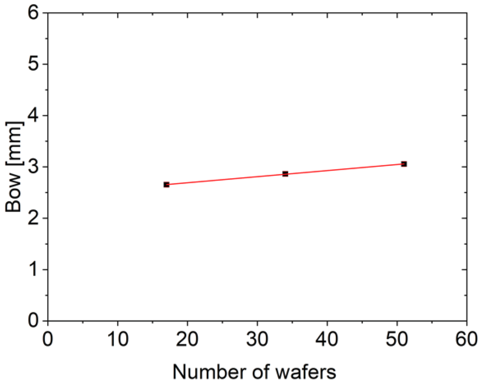
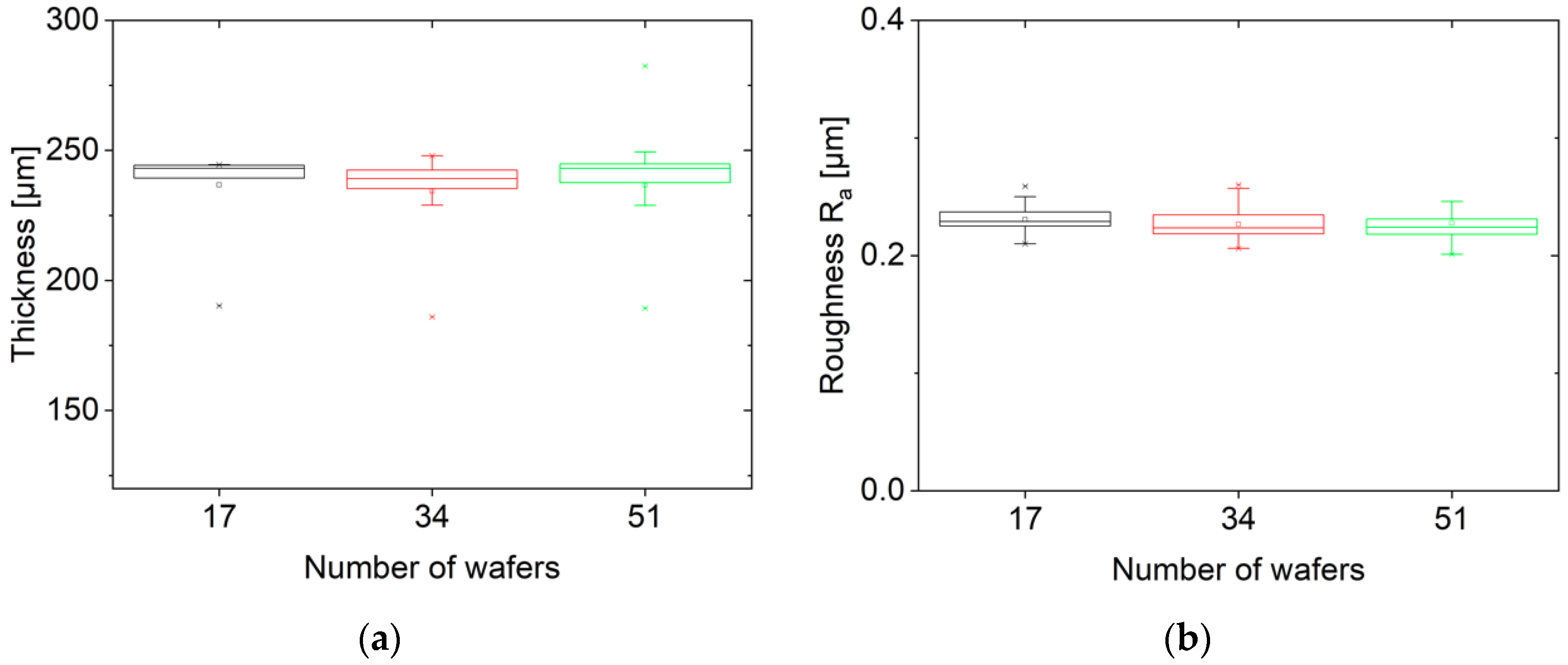
3.2. Variation of the Number of Wafers

In addition to the workpiece length, the influence of the number of wafers (increasing workpiece width) on the size of the bow was analyzed. A tripling of the number of wafers increases the size of the bow by approximately 15%. A linear relationship between the size of the bow and the number of wafers could be observed.
The size of the bow per wafer increases by 0.012 (±0.001) mm/wafer in the range of 17–51 wafers cut in one process (Figure 8). This is only a moderate loss of cutting ability with an increasing amount of wafer. The total load on the wire during the sawing process increases as the wire web enters the ceramic block over an increased number of sawing channels while the contact area As Equation (3) per wire in contact with the workpiece remains constant at 21.8 mm2. The observed size of the bow changes from 2.7 mm for 17 wafers to 3.1 mm for 51 wafers. As more wafers are cut in a process, the structured wire is elongated more strongly, reducing the effective wire diameter (Figure 5). The number of abrasive grains m Equation (2), transported into a sawing channel decreases as the wire is elongated. Since the parameter m is proportional to the material removal rate, the cutting ability decreases when the number of abrasive grains in the sawing channel decreases. An increase in the size of the bow is the result of an increased number of wafers cut in one process.
Figure 9a shows no significant increase in the thickness variation of the wafers with the growing number of wafers. The roughness measurements are all in the range of Ra = 0.20 to 0.25 µm (Figure 9b).

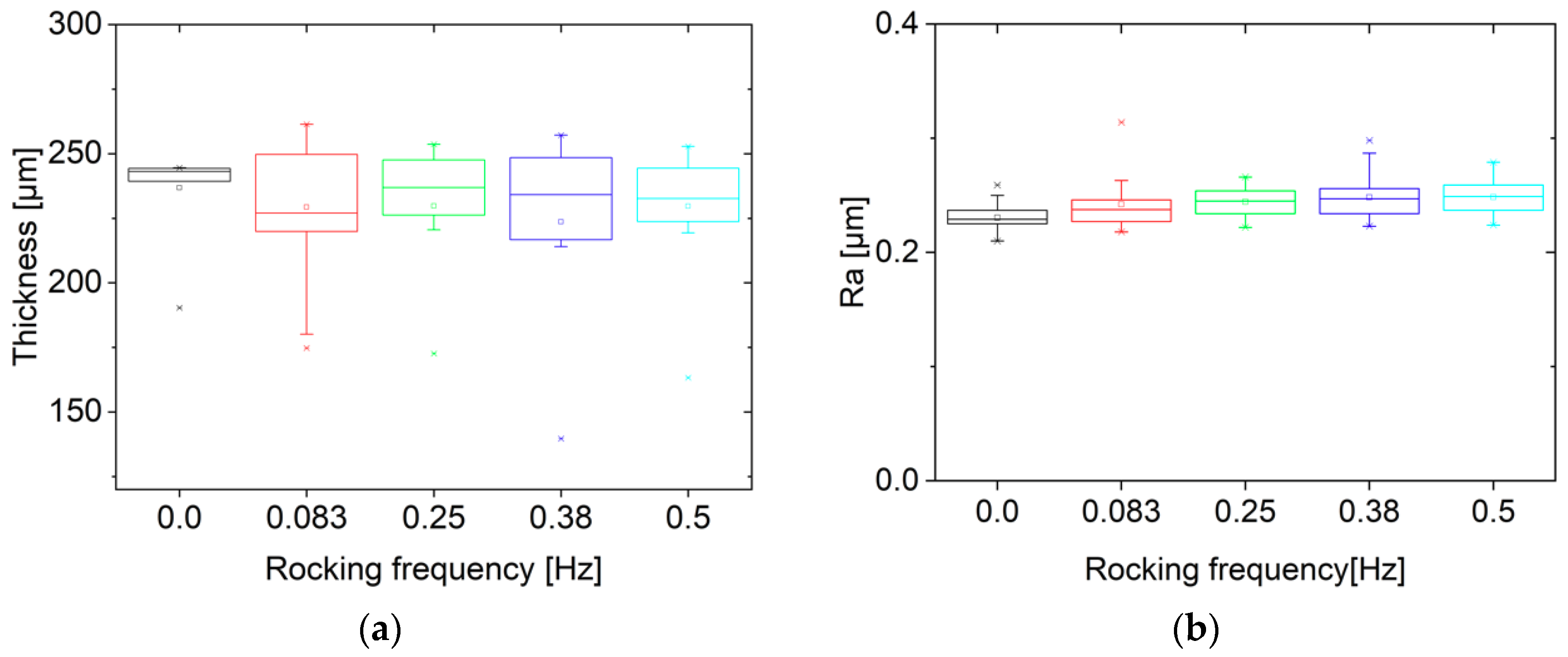
3.3. Variation of the Rocking Frequency

In the third experiment, the influence of the sawing parameter of the rocking frequency on the size of the bow was investigated. Four sawing processes with the rocking frequencies of 0.083, 0.25, 0.38, 0.5 Hz were performed.
In Figure 10, the bow values are plotted with increasing rocking frequency. No recognizable linear correlation is visible. Likewise the thickness and roughness measurements in Figure 11a,b do not show a linear correlation to the rocking frequency. An improvement in the cutting ability of the alumina ceramic through the use of the rocking unit has not been achieved.

3.4. Wear of the Abrasive Particles

Part of the sawing process monitoring includes the grain size analysis of the abrasive particles. All grain size measurements from the experiment I–III are listed in Figure 12a. A negative linear relationship between the boron-carbide grain size and the cut area during multi-wire sawing in the range of 0–0.43 m2 is found. The heavy wear of the boron-carbide grains is caused by splintering due to the mechanical stresses in the sawing channel. The d50 value after a cut area of 0.43 m2 has decreased from 22.3 to 18.0 µm. The slope of the linear fit shows a wear rate of the d50 value of −10.2 (±0.5) µm per sawn m2. The d50 value is halved after a cut surface of approx. 1.1 m2. However, it has to be tested if the observed linear relationship holds also for lower d50 values. The d10 value shifts from 14.9–3.7 µm when 0.43 m2 are cut (Figure 12b). An increased fine-grain fraction, as well as the smaller grain size, have a detrimental effect on the cutting ability and lowering the material removal rate during multi-wire sawing [13].
A reordering of the measured bow values of the sawing processes with the rocking frequencies of 0; 0.083; 0.25; 0.38; 0.5 Hz from 3.3 (Figure 10) over the chronological order of the processes and increasing degree of wear of the abrasive grains, shows a linear relationship between the cutting ability (size of the bow) and size of the abrasive particles.
In Figure 13, an increase of the size of the bow of 0.2 (±0.1) mm per µm d50 value of the abrasive particles in the range of 22.3–18.8 µm can be detected. The wear reduces the number of large grains involved in the removal process (Figure 12b), which lowers the material removal rate. No samples for grain size measurements could be taken after the sawing experiments with a rocking frequency of 0 and 0.38 Hz. Thus the d50 grain sizes of 21.3 and 20.0 µm at a cut area of 0.11 and 0.24 m2 are extrapolated from the observed linear wear rate of the boron-carbide grains (Figure 12a). An increase in the variation of the wafer thickness was observed with a decreasing d50 value of the abrasive grain size. The roughness measurements do not show this trend but are in the range of Ra = 0.2 to 0.3 µm (Figure 14a,b). The heavy wear of the abrasive grains must be taken into account to avoid wire rupture when cutting large blocks.
Due to the mechanical properties of the used translucent alumina ceramic, the workpiece can only be cut with a feed rate of the table of 20 µm/min. The formation of the bow of the wire web leads to a cutting speed of −17 µm/min under the experimental conditions. When multi-wire sawing of silicon, feed rates > 700 µm/min are possible [8]. Under the process conditions investigated in this study, no measurable wire bow would occur when cutting silicon. Figure 15 summarizes the main results of the study on the size of the bow during multi-wire sawing of the used alumina ceramic. The slopes of the linear regressions of the analyzed variations (workpiece length, number of wafers, rocking frequency, wear of the abrasive grain size) with their standard-errors as error bars are displayed in this bar chart. The influence of the workpiece length and the number of wafers on the size of the bow is much greater than the scatter in the experiments. Thus, these parameters have to be accounted for when choosing the cutting parameters. The influence of the rocking frequency on the size of the bow compared to the experiment scatter is small, hence no or only a very small influence is to be expected. Despite the strong scatter of abrasive wear, a clear dependence on the cutting ability was demonstrated.

4. Conclusions

(1)
As presumed from the model of Möller et al. [7] an increase of the workpiece length has a negative effect on the material removal rate and thus the cutting ability. The range of 37.5–150 mm workpiece length was analyzed. An increase of the size of the bow by 0.03 mm per mm of workpiece length was found. The thickness variation of the wafer material increases with increasing workpiece length.
(2)
Furthermore, the increase in the number of wafers reduces the cutting ability in the sawing process. In the range of 17–51 wafers, an increase of 0.01 mm bow per additional wire was been observed. The roughness values of the wafers are in the range of 0.20 to 0.25 µm and no thickness variation was found. This study showed that the size of the bow reacts by the factor of three more strongly to an extension of the workpiece length than to an increase in the number of wafers. To keep the size of the bow as small as possible, the block should be positioned in such a way that the working length is not the longest block edge.
(3)
When using the rocking unit the cutting ability of the Al2O3 ceramics cannot be improved. Any influence of the rocking frequency on the cutting ability was overlaid by the influence of the heavy wear of the abrasive grains. To see the influence of the rocking unit, a new batch of boron-carbide grains would have to be used for each process.
(4)
The wear of the boron-carbide abrasive grains causes an increase of the size of the bow of 0.02 mm per 0.01 µm wear of the d50 value of the abrasive particles. They have a wear rate of about 10.2 µm per cut m2. An increase in the variation of the wafer thickness became visible with decreasing abrasive grain size. This influence must, in any case, be accounted for when sawing ceramic blocks with a large cut surface (>0.43 m2) to avoid wire rupture. None of the examined parameters has a strong influence on the roughness of the ceramic wafers, thus enabling a reliable production of alumina ceramic wafers with uniform roughness values under the examined conditions.

Author Contributions

Conceptualization, L.S., M.F. and T.K.; methodology, H.H. and M.F.; validation, L.S., H.H. and M.H.; formal analysis, L.S. and H.H.; investigation, L.S.; data curation, L.S.; writing—original draft preparation, L.S.; writing—review and editing, A.P., S.J., M.H. and C.A.; visualization, L.S. and M.H.; supervision, A.P., M.H. and T.K.; project administration, A.P. and T.K. All authors have read and agreed to the published version of the manuscript.

Funding

This research received no external funding.

Conflicts of Interest

The authors declare no conflict of interest.

References

  1. Teomete, E. Mechanics of Wire Saw Machining Process: Experimental Analyses and Modeling. Ph.D. Thesis, Iowa State University, Ames, IA, USA, 2008. [Google Scholar]
  2. Li, Z.C.; Pei, Z.J.; Funkenbusch, P.D. Machining processes for sapphire wafers: A literature review. Eng. Manuf. 2011, 225, 975–989. [Google Scholar] [CrossRef]
  3. Wu, H. Wire sawing technology: A state-of-the-art review. Precis. Eng. 2016, 4, 1–9. [Google Scholar] [CrossRef]
  4. Yang, F.; Kao, I. Free Abrasive Machining in Slicing Brittle Materials with Wiresaw. J. Electron. Packag. 2001, 123, 254–259. [Google Scholar] [CrossRef]
  5. Buijs, M.; Korpel-van Houven, K. 3-body abrasion of brittle materials as studied by lapping. Wear 1993, 166, 237–245. [Google Scholar] [CrossRef]
  6. Buijs, M.; Korpel-van Houven, K. A model for lapping of glass. J. Mater. Sci. 1993, 28, 3014–3020. [Google Scholar] [CrossRef]
  7. Möller, H.J. Basic Mechanisms and Models of Multi-Wire Sawing. Adv. Eng. Mater. 2004, 6, 501–513. [Google Scholar] [CrossRef]
  8. Bidiville, A.; Wasmer, K.; Michler, J.; Nasch, P.M.; Van der Meer, M.; Ballif, C. Mechanisms of wafer sawing and impact on wafer properties. Prog. Photovolt. Res. Appl. 2010, 18, 563–572. [Google Scholar] [CrossRef]
  9. Theophil, L. Anpassung der Diamantdrahtsägeprozesse Für Eine Bessere Texturierfähigkeit von Multikristallinen Siliziumwafern. Master’s Thesis, TU Freiberg, Freiberg, Saxony, Germany, 2019. [Google Scholar]
  10. Gehl, E. Untersuchung der Topografie und Oberflächenschädigung an Siliziumwafern, Die Mit Unterschiedlichen Kühlschmierstoff und Prozessparametern Hergestellt Wurden. Bachelor’s Thesis, TU Freiberg, Freiberg, Saxony, Germany, 2014. [Google Scholar]
  11. Weber, B. Untersuchung der Material Begrenzenden Einflüsse beim Multidrahtsägen von Silicium Unter Verwendung Gerader und Strukturierter Drähte. Ph.D. Thesis, TU Freiberg, Freiberg, Saxony, Germany, 2015. [Google Scholar]
  12. Meißner, D.; Schoenfelder, S.; Hurka, B.; Zeh, J.; Sunder, K.; Koepge, R.; Wagner, T.; Grün, A.; Hagel, H.J.; Möller, H.J.; et al. Loss of wire tension in the wire web during the slurry based multi wire sawing process. Sol. Energy Mater. Sol. Cells 2014, 120, 346–355. [Google Scholar] [CrossRef]
  13. Nassauer, B.; Kuna, M. Impact of micromechanical parameters on wire sawing: A 3D discrete element analysis. Comput. Part. Mech. 2015, 2, 63–71. [Google Scholar] [CrossRef] [Green Version]
Figure 1. Field emission scanning electron microscopy (FESEM) image of the polished cross section of the used Al2O3 ceramics.
Jmmp 04 00002 g001
Figure 2. Translucent multi-wire sawn alumina ceramic wafer from the feasibility study: (a) dimensions: 80 mm × 65 mm × 0.5 mm; Ra = 0.3 µm; (b,c) FESEM images of the as cut wafer surface.
Jmmp 04 00002 g002
Figure 3. 1: Wire guide rollers; 2: Fresh wire; 3: Wire web; 4: Workpiece; 5: Top plate; 6: Slurry nozzles; 7: Used wire (H—height; L—length, W—width of the workpiece) [10].
Jmmp 04 00002 g003
Figure 4. 1: Bow of wire web; 2: Feed direction; 3: Compact part of the workpiece; 4: Processed part of the workpiece.
Jmmp 04 00002 g004
Figure 5. Model of fresh structured wire; 1: wire; 2: effective wire diameter.
Jmmp 04 00002 g005
Figure 6. Bow measurements depending on the variation of the workpiece length (slope = 0.035 (±0.001); COD (r2): 0.99).
Jmmp 04 00002 g006
Figure 7. (a) Thickness variation for different workpiece lengths, (b) roughness values for different workpiece lengths.
Jmmp 04 00002 g007
Figure 8. Bow measurements in dependence of the variation of the number of wafers ( y = 0.012   ( ± 0.001 )   x + 2.46   ( ± 0.01 ) , COD (coefficient of determination) (r2): 0.99).
Jmmp 04 00002 g008
Figure 9. (a) Thickness variation for different numbers of wafers, (b) roughness values for different numbers of wafers.
Jmmp 04 00002 g009
Figure 10. Bow measurements depending on the variation of the rocking frequency ( y = 0.53   ( ± 0.53 )   x + 2.81   ( ± 0.16 ) ; COD (r2): 0.25).
Jmmp 04 00002 g010
Figure 11. (a) Thickness variation for different rocking frequencies; (b) roughness values for different rocking frequencies.
Jmmp 04 00002 g011
Figure 12. (a) Wear rate of the boron-carbide d50 value ( y = 10.2   ( ± 0.5 )   x + 22.5   ( ± 0.1 ) ; COD (r2): 0.99), (b) particle-size distribution before and after use.
Jmmp 04 00002 g012
Figure 13. Effect of abrasive particle wear on the size of the bow ( y = 0.2   ( ± 0.1 )   x + 7   ( ± 1.5 ) ; COD (r2): 0.72). The d50 grain sizes of the grey marked data points are not measured experimentally.
Jmmp 04 00002 g013
Figure 14. (a) Thickness variation for different abrasive grain sizes, (b) roughness values for different abrasive grain sizes.
Jmmp 04 00002 g014
Figure 15. Variation of different sawing parameters and their influence on the increase of the bow.
Jmmp 04 00002 g015
Table 1. Mechanical properties of the Al2O3 ceramic material.
Parameter
ProcessHIP Al2O3
Relative density99.8%
Grain size d50 value [µm]0.44
Vickers hardness (H)2279 HV0.5 ± 1
2220 HV1 ± 5
2168 HV2 ± 13
Elastic modulus (E) [GPa]436 ± 6
Fracture toughness (KIC 4PB) [MPa·m0.51/2]3.7 ± 0.2
Bending strength (4PB) [MPa]700 ± 80
Table 2. Common process parameters.
Sawing Parameters
Wire conditionNew
Wire speed [m/s]14
Wire tension [N]25
Pitch [mm]0.425
Wire nominal diameter [mm]0.115
B4C abrasive size d50 value [µm]22.5
Table feed rate [mm/min]0.02
B/F ratio0.64

