Article

Effect of Heat-Treatment on the Thermal and Mechanical Stability of Ni/Al2O3 Nanocrystalline Coatings

1
Faculty of Engineering and Informatics, University of Bradford, Richmond Road, Bradford BD7 1DP, West Yorkshire, UK
2
King Abdullah Institute for Nanotechnology, King Saud University, Riyadh 11451, Saudi Arabia
*
Author to whom correspondence should be addressed.
J. Manuf. Mater. Process. 2020, 4(1), 17; https://doi.org/10.3390/jmmp4010017
Submission received: 28 January 2020 / Revised: 20 February 2020 / Accepted: 25 February 2020 / Published: 28 February 2020

Abstract

:
Heat-treatment is a frequently used technique for modifying the physical and chemical properties of materials. In this study, the effect of heat-treatment on the mechanical properties, thermal stability and surface morphology of two types of electrodeposited coatings (pure-Ni and Ni/Al2O3) were investigated. The XRD analyses showed that the crystal structure of the as-deposited coating changes from slightly amorphous to crystalline as the heat-treatment temperature increases. The heat-treatment of both the pure-Ni and the Ni/Al2O3 coating caused an increase of the grain size within the coatings. However, the unreinforced Ni coating experienced a faster growth rate than the Ni/Al2O3 coating, which resulted in a larger average grain size. The temperature-driven changes to the microstructure of the coatings caused a reduction in the hardness and wear resistance of the coatings. The presence of nanoparticles within the Ni/Al2O3 coating can successfully extend the operational temperature range of the coating to 473 K by pinning grain boundaries.

1. Introduction

Electrophoretic deposition (EPD) is an inexpensive method of producing composite coatings containing ceramic particles ranging from nano-metric dimensions to several micrometer sizes [1]. In EPD, charged colloidal oxide/ceramic particles dispersed or suspended in a liquid medium are attracted and deposited onto a conductive substrate of opposite charge [2]. Several studies have explored EPD with the objective to understand the mechanism of deposition and to identify potential applications of the technology [2,3,4].
The production of thin hard nanocomposite coatings by EPD has been shown to possess several technological advantages [2]. The ability of the process to deposit nano-sized ceramic particles into the coating enables engineers to create multifunctional materials capable of withstanding extreme tribological applications [5]. The success of EPD in producing wear-resistant coatings is dependent on the coating parameters selected during the deposition process. Parameters such as current density, particle concentration, pH, surfactant concentration, stir rate, and temperature, have been shown to affect the properties of the coatings [1,6,7,8]. Current density has been shown to positively affect the wear resistance of the coatings, because as the current density increases, the grain size of the nickel matrix decreases, which strengthens the coating and increases its wear resistance [9,10]. Similar observations were made by Jung et al. who studied Ni/Al2O3 coating [11]. The impact of particle concentration has a similar effect on the wear resistance of the coating, as the concentration of particle suspended in the solution increases, the volume of particles embedded into the coating during deposition also increase, which causes the hardness of the coating to increase [10,12]. The literature shows that as the volume of the surfactant increases, the zeta potential of the nanoparticles also increases, which prevents particle agglomeration during the electrodeposition process and improves particle distribution, which positively affects wear resistance of the coating [3,13].
The inclusion of the nanoparticles within the metal matrix and the uniformity of its distribution is critical to achieving good quality, wear resistance coating [14,15,16]. Poor bonding between the ceramic particles and the matrix has been an important limitation to the wide scale industrial application of EPD processes [17]. However, the particle-matrix bond strength can be improved by post-deposition heat treatment. Only limited research exists on the appropriate temperature to facilitate activation of the densification mechanisms within coating [2]. The challenges experienced with identifying suitable heat-treating temperatures for EPD nanocomposite coatings are based on the differences between the properties of the ceramic particles, the metal matrix, and the substrate. If the heat treatment temperature is too high, melting of the matrix or substrate may occur, whereas if the temperature is too low, densification of the coating is not achieved [18]. Cooke and Khan showed that heat treatment temperatures have significant effects on the tribological performance of Ni/TiO2 coatings [19]. However, data is limited to the effect of thermal processing on the microstructure, thermal stability and tribological behavior of Ni-based coatings containing other types of reinforcements.
This study will evaluate the relationship between thermal processing, elevated temperature stability and sliding wear performance of Ni/Al2O3 coatings. The coating surface morphology, phase analysis, and hardness were also systematically investigated and compared to the pure Ni coating, which was used as a control.

2. Experimental Procedure

Two electrochemical baths were prepared from a standard Watt’s nickel bath solution. Bath-1 was used to deposit pure-Ni coatings without the addition of oxide particles. The Ni/Al2O3 coating was deposited from Bath-2 containing 20 g/L of Al2O3 particles. A 99.5% pure nickel plate was used as the anode and AISI1020 carbon steel of dimension 25.4 mm × 20 mm × 6 mm was used as the cathode. The distance between the two electrodes was maintained at approximately 2 cm during the deposition process. The electrodeposition process was carried out at 323 K and a current density of 5 A/dm2 for 30 min under constant magnetic stirring (approximately 250 rpm) to prevent particle agglomeration during deposition. The constituents of baths and the optimum parameters for the deposition process for Ni/Al2O3 were discussed in published articles [16,18,20]. The test cell was a 250 mL beaker containing the electrolyte bath solution.
The alumina powder having a particle size of 40 nm was obtained from Goodfellow (Cambridge, UK). The alumina powder was selected because of the significant increases in wear resistance observed in previous studies [19,20]. For comparison, pure Ni coatings were prepared from the same solution, without the addition of nanoparticles and using the same coating parameters. The thickness of the as-deposited coatings was at least 134 ± 2 µm, which was determined using SEM. Prior to the deposition process, the steel substrates were prepared using abrasive papers from 240 to 1200 grit size, polished to 1 μm using particle-impregnated carrier paste, degreased with acetone, and rinsed in distilled water. After the electrodeposition process, the cathode was extracted from the cell and rinsed with distilled water.
The coated samples were heat treated in air using an induction furnace equipped with a temperature control system. A thermocouple was attached to each sample and monitored throughout the heating and cooling process. The specimens were heated at a rate of 60 K/min to the annealing temperature of 473 K and 673 K, where the samples were kept for 30 min before the power was switched off and the specimens cooled in air to room temperature. These temperatures were selected based on the recrystallization temperature of nickel, which has been shown to vary between 593 K and 653 K to ensure the recrystallization of the coatings [5].
Micro-hardness tests were performed on the cross-section of the coatings according to ASTM E92 standard test method for Vicker’s micro-hardness testing. The micro-hardness measurements were carried out using a Leitz micro-hardness tester. Ten indentations were measured on each sample using a 0.1 kg load applied for 30 s.
The wear tests were completed using a linear reciprocating pin-on-plate test machine equipped with a diamond pin of diameter 3 mm, mounted in a 90° cone. A schematic of the test setup is shown in Figure 1. The pin slides reciprocally against the coated specimen and the wear performance measured by monitoring the changes in the depth of the wear scar as a function of time for 30 min. The wear rate was determined by dividing the scar depth by the duration of the wear test. The tests were conducted under non-lubricating conditions in air having a relative humidity of 87 ± 5% and an ambient temperature of 295 ± 1 K. To ensure repeatability, three specimens were heat treated and tested for each test condition. The applied load was varied between 10, 25, and 40 N. The test data were collected using a 16-bit 100 kHz data acquisition system (USB-1608FS model from micro DAQ, Contoocook, NH, USA).
The surface morphology of the coatings and the wear scars were examined using a Leitz optical microscope, an Olympus laser scanning confocal microscope, and Hitachi TM3000 desktop scanning electron microscopy (SEM). The chemical composition of the coatings and the concentration of nanoparticles in the Ni/Al2O3 coatings were evaluated using INCA X-sight energy dispersive spectroscopy (EDS) system attached to the Scanning electron microscope (FEI Quanta 400, Oxford, UK). The effect of heat treatment on the crystal structure of the coating was studied using a Bruker x-ray diffractometer (XRD) with Cu-Kα radiation. Diffractograms were recorded with a voltage of 40 kV, current 40 mA, step-size of 0.05° from 2θ ranging from 10° to 100°, and measuring time 1 s per step.

3. Results

3.1. XRD Analyses

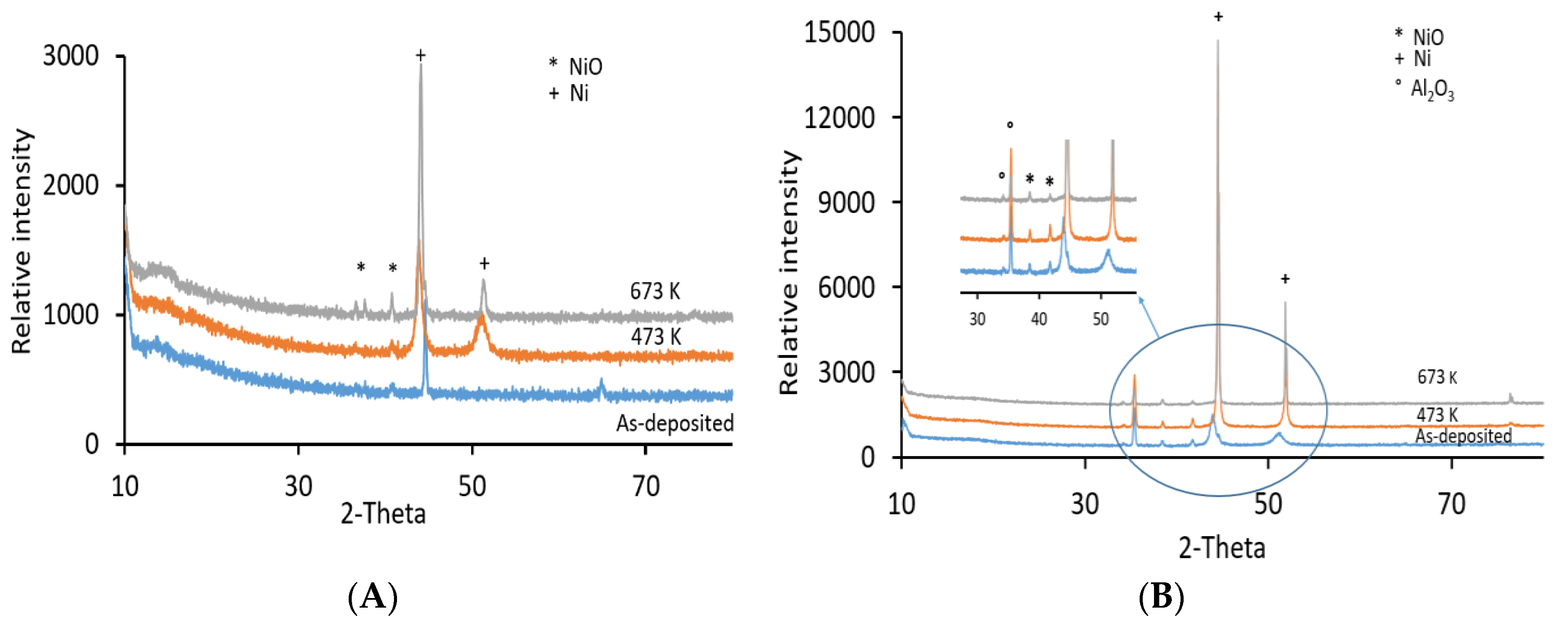
XRD analyses of the coatings were conducted to identify any phase changes or modifications to the diffraction peaks due to heat treatment. The results collected showed that the heat treatment process modified the structure of the coatings (see Figure 2). The diffractograms of the as-deposited pure Ni coating are characterized by peaks of NiO and metallic Ni as shown in Figure 2A. When the heat treatment temperature was increased to 673 K, the XRD spectra of pure Ni deposit (Figure 2A) showed an increase in the intensity and sharpness of the peaks occurring at 2θ = 44.34°, and 51.8°, and the formation of two additional peaks of NiO. Similar behavior was observed for the XRD analysis of the Ni/Al2O3 coating with weak peaks for the Al2O3 nanoparticles was very weak relative to the intensity of the Ni the peak (see Figure 2B).

3.2. Microstructural Analyses and Surface Morphology

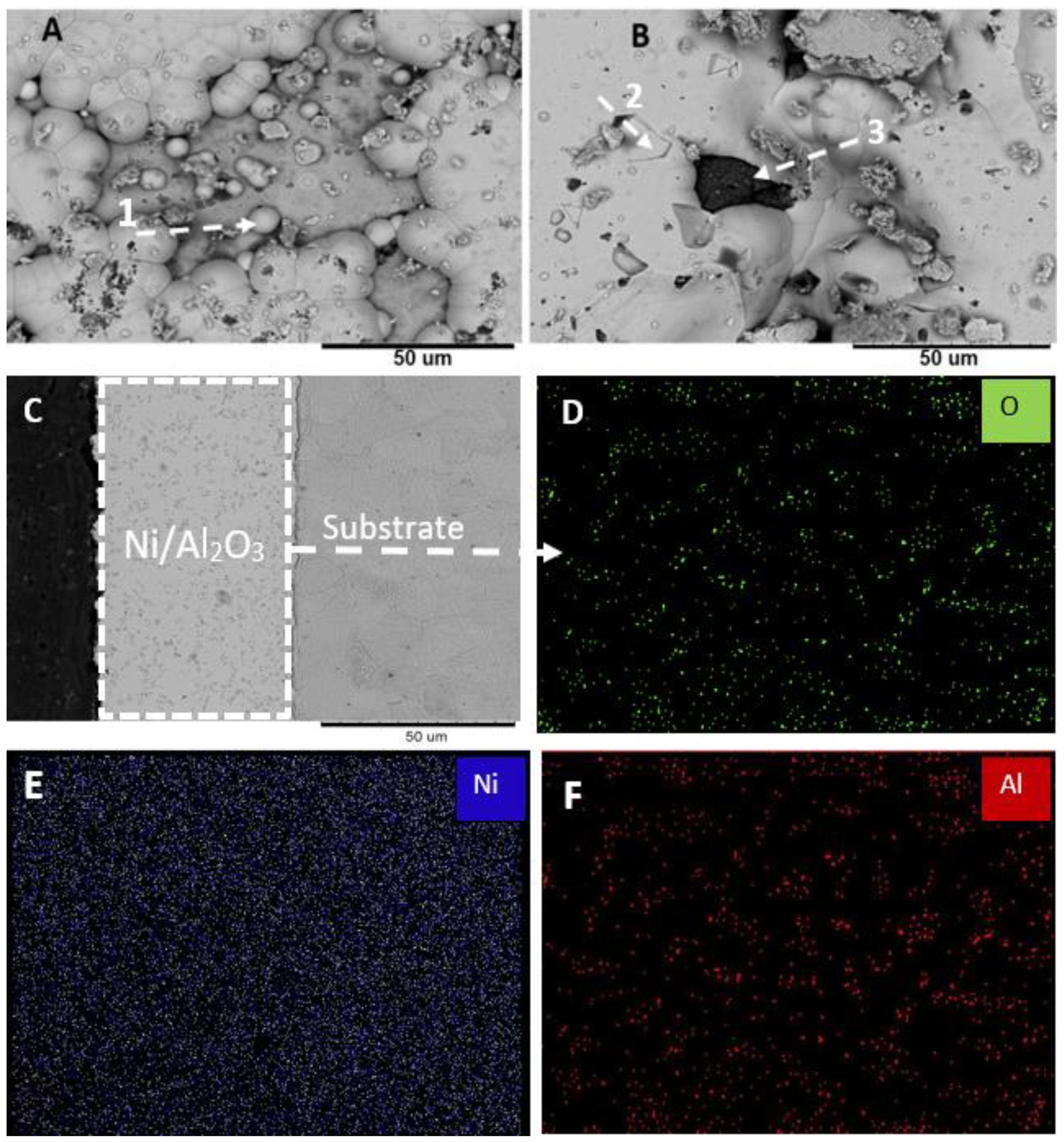
Analysis of the coating by SEM revealed numerous differences between the surface morphology of the nanocomposite coatings and the pure nickel coating before and after heat treatment. The surface of the as-deposited Ni/Al2O3 coating is presented in Figure 3 and shows evidence of spherical protrusions at the surface (point-1), which appears to be grains interspersed by oxide particles. Figure 3B shows the presence of a structure labeled as point-2, which is believed to be pseudo-pentagonal crystal symmetry typically found in pure nickel coatings [21]. EDS analysis (7.58C, 11.37O, 43.12Si, 37.9Ca) wt.% of the dark spot labels point-3 suggests that are non-conducting contaminants embedded in the steel during preparation and caused the formation of a cavity during the deposition process. The SEM micrograph of the cross-section of the coating presented in Figure 3C also shows the presence of Al2O3 particles distributed through the cross-section of the coating. Chemical compositional map of the cross-section of the coating using EDS confirms the presence of Al2O3 particles as by Al and the high oxygen content (see Figure 3D). A point counting analysis was performed using ImageJ software (National Institutes of Health, Bethesda, Rockville, MD, USA), which indicated that the Al2O3 content within the cross-section of the nanocomposite coating was approximately 18.4 wt.%.
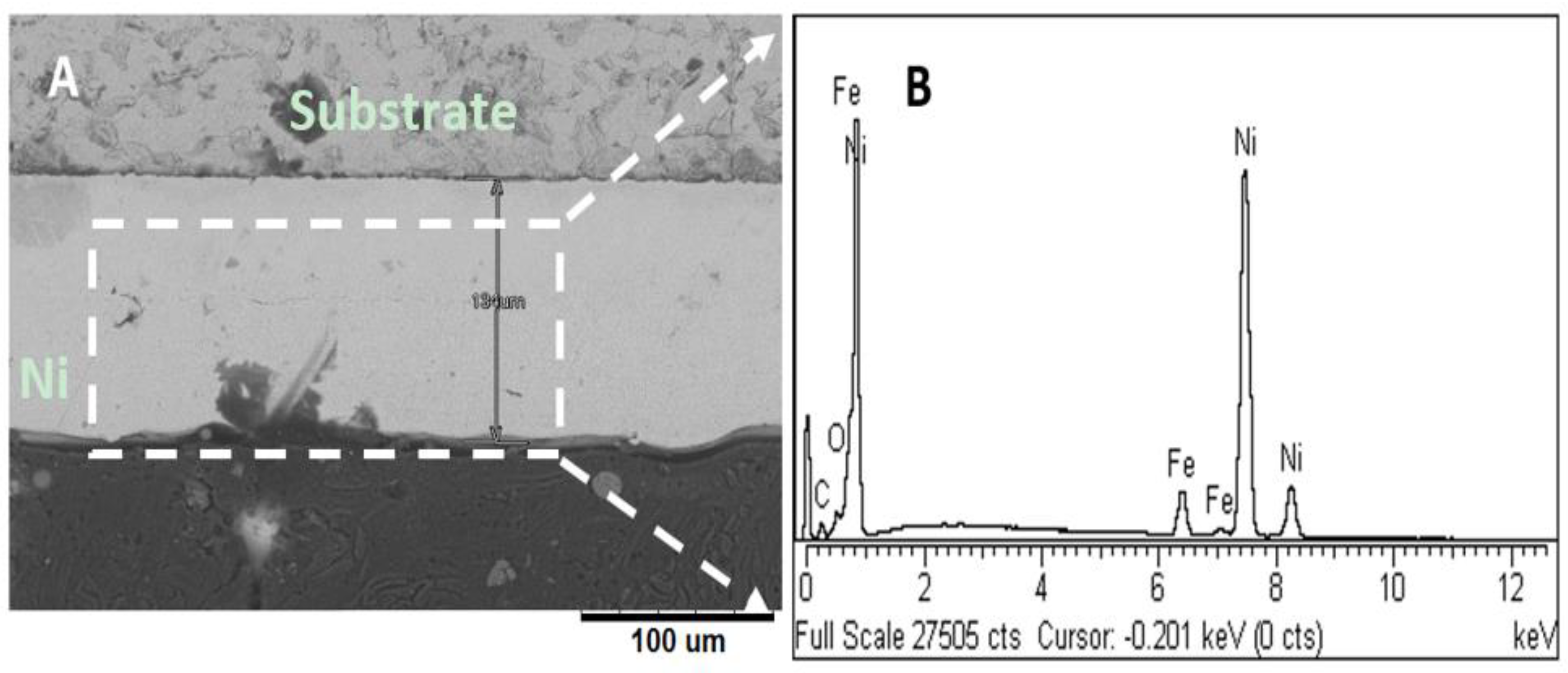
Comparing the results of the Ni/Al2O3 coating to those of the pure Ni-coating presented in Figure 4. The cross-section of the as-deposited Ni-coating appears to be uniform, without the presence of defects. A lateral micro-crack was observed in the coatings as shown in Figure 4A, this is likely to have formed during the cutting and preparation of the coating for microscopic analyses. From Figure 4A, it can be observed that the thickness of the pure Ni coating and the nanocomposite coatings have similar values of approximately 134 µm. The EDS analysis of the pure Ni coating presented in Figure 4A shows strong peaks for Ni and very low oxygen content.
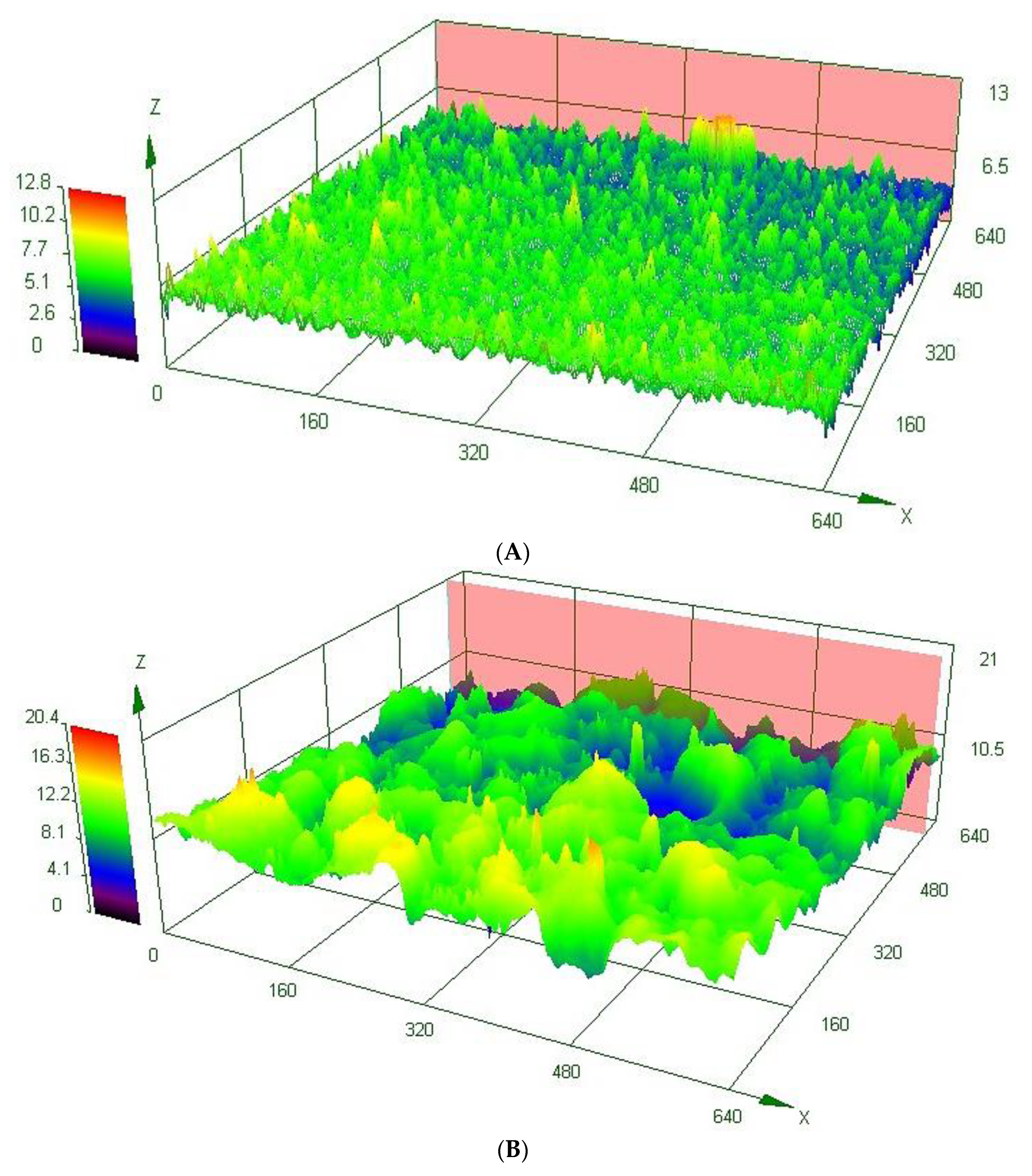
Confocal micrographs of the surfaces of the coatings before and after heat treatment to 673 K are presented in Figure 5 and illustrate that the morphology of the coatings changed significantly with increasing temperature. The results demonstrate that as the heat treatment temperature increased, the surface of the coating displayed a greater degree of waviness when compared to coating heat treated to lower temperatures (see Figure 5). The waviness of the surface is believed to be evidence of grain coalescence and the densification of the coating. The changes observed at the surface of the coatings resulted in an increase of the average surface roughness of all three coatings tested as shown in Table 1.

3.3. Hardness

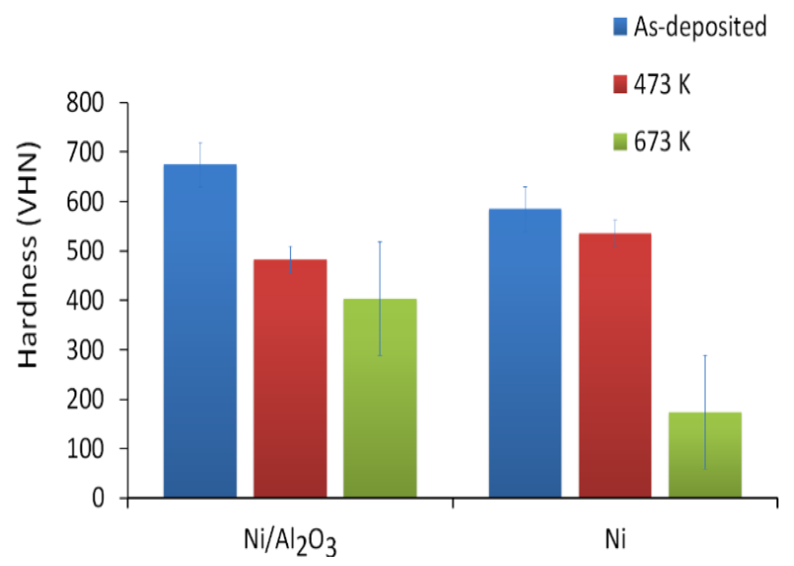
Figure 6 shows the effect of processing temperature on the micro-hardness of the coatings. The as-deposited Ni/Al2O3 coatings recorded a hardness of 664 VHN. When the Ni/Al2O3 sample was heat-treated, the hardness number decreased to 450 VHN at 473 K and 395 VHN at 673 K. When the pure Ni coating was heat-treated, the hardness number decreased from 585 VHN for the as-deposited coating to 174.4 VHN for the samples heat-treated to 673 K.

3.4. Sliding Wear Performance of the Coatings

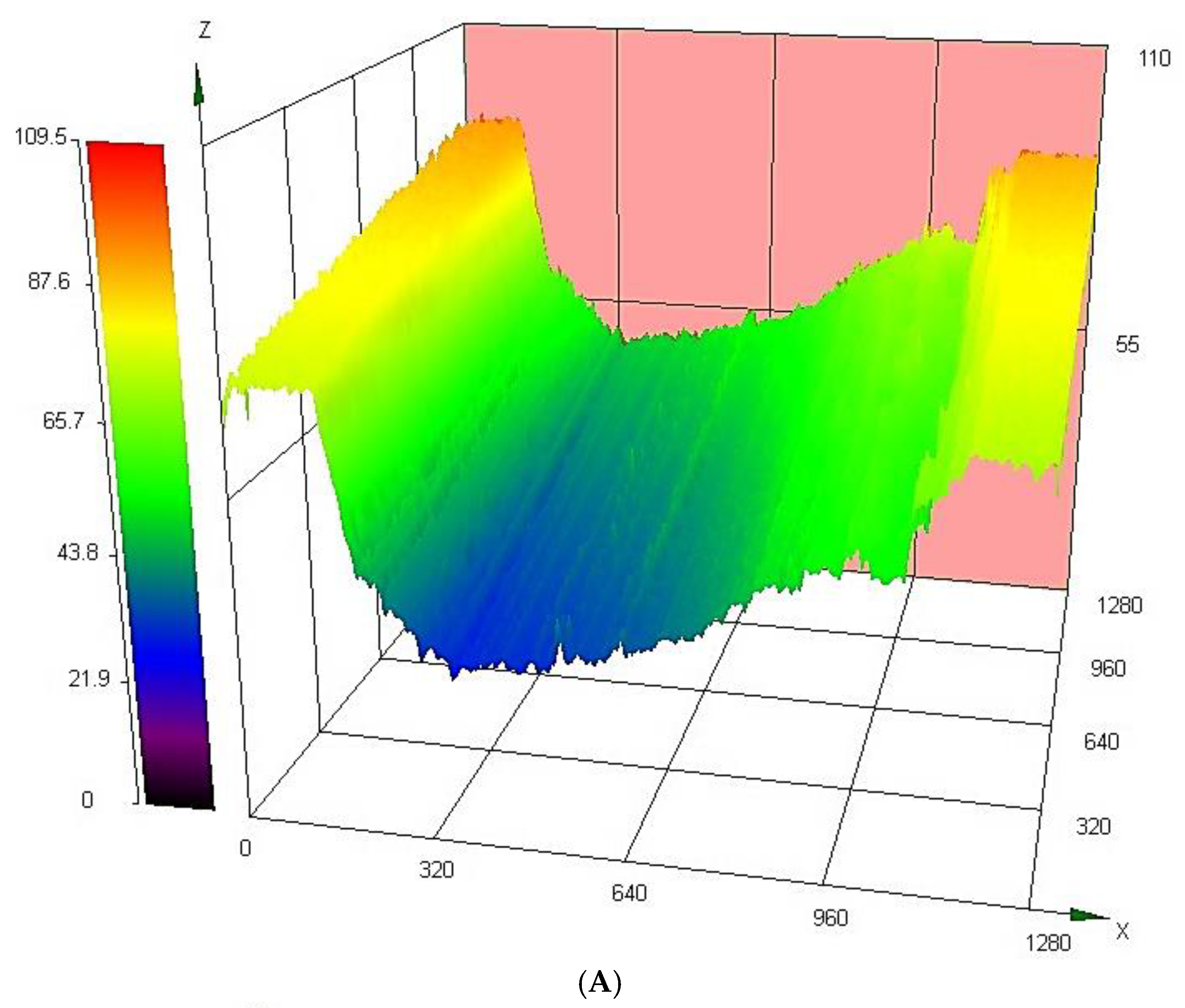
The wear tests were performed to evaluate the effects of heat treatment on the sliding wear behaviour of the coatings. The depth of the wear scar was recorded using a laser scanning confocal microscope. A typical wear profile for the nanocomposite coatings is shown in Figure 7. The wear rate of the coatings was determined by dividing the depth of the wear scar by the duration of the wear test.

3.4.1. Effect of Load on the Sliding Wear Performance

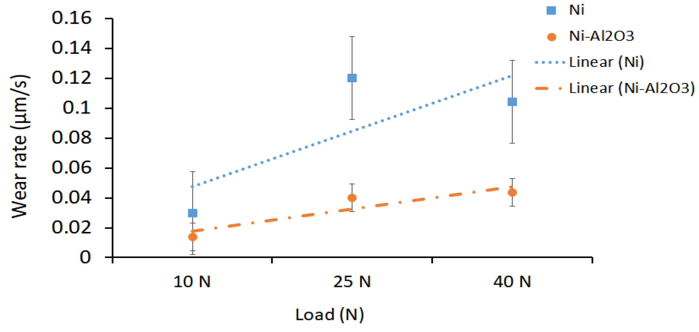
The effect of load on the sliding wear behavior of the as-deposited coatings was evaluated by varying the load from 10 N to 40 N. The wear rates recorded for each coating are shown in Figure 8. The best-fit curve through the data suggests that the wear rate of the as-deposited Ni coating increased with increasing load from 0.05 µm/s to 0.11 µm/s. Similarly, for the Ni/Al2O3 coating, the wear rate increased from 0.02 µm/s at 10 N to 0.04 µm/s at 40 N. The results show that in the as-deposited condition, the Ni/Al2O3 nanocomposite coating had better wear resistance than the pure Ni coatings.

3.4.2. Effect of Heat Treatment Temperature on the Sliding Wear Performance

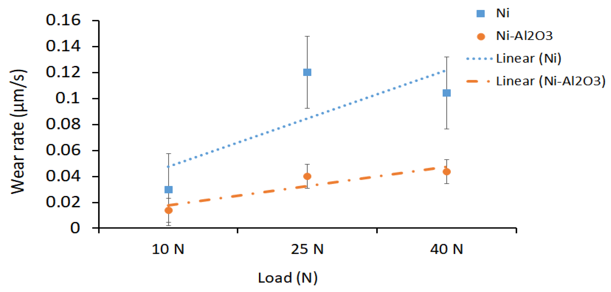
Figure 9 shows the effects of heat treatment temperature on the wear rate of the coatings tested at a load of 10 N. The results demonstrate that as the heat treatment temperature increased, the wear rate increased from 0.03 µm/s for the as-deposited Ni coating to 0.11 µm/s for the coating was annealed to 673 K. On the other hand, the wear rate of the nanocomposite coatings was observed to increase with increasing annealing temperature. The wear rate of the Ni/Al2O3 coating marginally decreased from 0.002 µm/s to 0.001 µm/s at 673 K. The differences in the behavior of the coatings tested at 10 N suggest that the smaller Al2O3 particles are more effective at pinning grain boundaries at higher temperatures [22].

3.4.3. Analysis of Wear Track

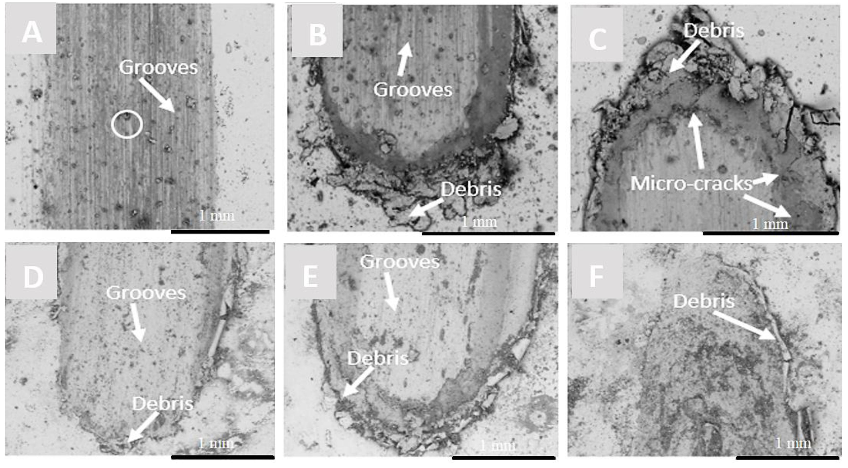
The wear scars of the as-deposited Ni coatings tested as a function of load for 10 N, 25 N and 40 N are shown in Figure 10A–C respectively. The surface of the coatings tested using 10 N contained a series of parallel grooves with small pin holes present in the groove track. The absence of wear debris suggests that at this load, the yield strength of the coating was not exceeded. However, increasing the load to 25 N and 40 N resulted in an expansion of the debris field and the formation of additional surface defects that are not found at a lower load. Similar, to the surface of the as-deposited Ni/Al2O3 coating, tested using 10 N, contained parallel grooves and large sheet-like debris at the bottom of the wear track with large delaminated regions (see Figure 10D–F). Close examination of the wear debris shown in Figure 10C suggests that bulk flaking may have also occurred at 25 N and 40 N test loads. At higher test loads, the yield strength of the coating was exceeded, which is believed to be responsible for the larger debris fields formed around the wear scars.
When the wear scars of the Ni/Al2O3 coatings were compared to the pure Ni coatings shown in Figure 10D–F, it was observed that as the load increased, the depth of the wear scar also increased. The surface of the as-deposited coating tested at 10 N had a small debris field along with grooves parallel to the sliding direction. When the load was increased to 25 N, similar parallel grooves were observed as well as large delaminated areas and large sheet-like debris at the end of the wear scar. Further increase of the load to 40 N resulted in the peeling of sections of the coating as shown in Figure 10F.
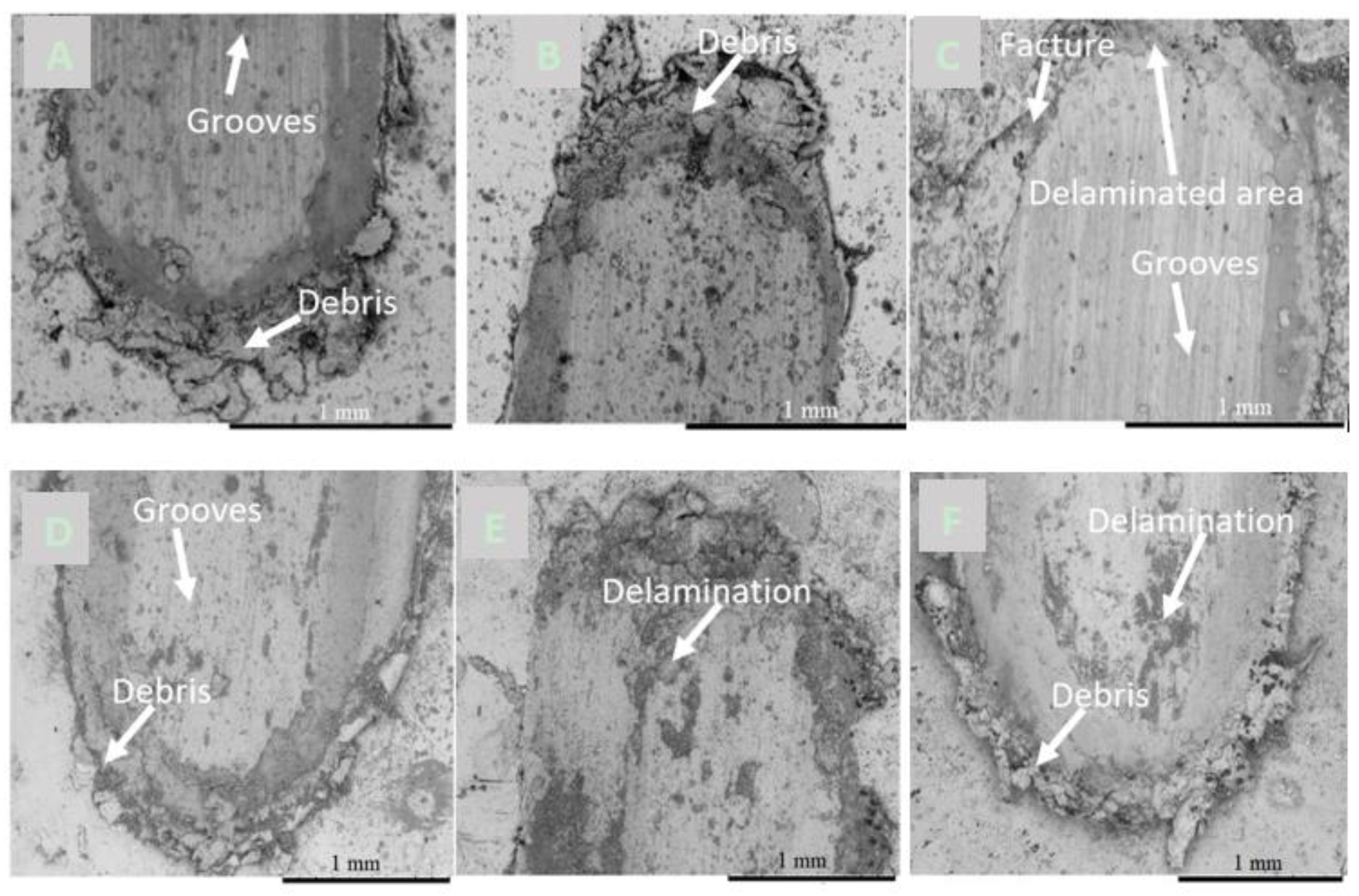
When the annealing temperature was increased to 473 K, similar parallel grooves were observed on the surface along with several delaminated areas as shown in Figurer 11B. Further increase of the load at this temperature resulted in an increase of the wear debris formed and the width of the wear track. When the annealing temperature was increased to 673 K, the depth of the wear scar also (see Figure 11C) increased.
Similarly, the wear scars of the Ni/Al2O3 coating tested as a function of temperature are shown in Figure 11D–F; the surfaces appeared to have been fractured during the wear test. The micrograph showed that the top layers of the coating were removed during the wear test. This was attributed to the reduction of the cohesive bond strength between the coating layers as the annealing temperature was increased. The presence of wear grooves on the surfaces suggest that the primary wear mechanism of the as-deposited coatings is abrasive wear. However, the delaminated regions and the fractures formed as the annealing temperature increased, which suggests that adhesive wear may have also occurred. As such, the mechanism can be described as a mixed mode to the heat-treated samples. These results support the hardness and grain sized data recorded, which shows that increasing annealing temperature caused the hardness to decrease as grain sizes within the coating increased.
The results show that as the temperature increased, the size of the wear scars and the debris fields also increased. These changes can be attributed to microstructural changes brought on by thermally activated grain growth. As the grain size increased, the ductility of the coating increased while the yield strength of the coating decreased. The Ni/Al2O3 coatings experienced a mixed mode of wear, which was represented by the presence of both abrasive grooves and several delaminated regions, which are believed to have formed due to a reduction of the cohesive forces between the layers of the coating as the annealing temperature was increased [15].

4. Discussion

4.1. Hardening Effect of Nanoparticles

When the XRD patterns were compared as a function of annealing temperature for the coatings tested, it was observed that in all cases the peaks of the XRD spectrum for the as-deposited coatings appear to be broader more rounded than the spectra of the coatings heat treated to 473 K and 673 K respectively. The broadness of the XRD peaks for the as-deposited coatings suggests the presence of an imperfect crystal lattice or amorphous structure. According to the theory of kinematical scattering, X-ray diffraction peaks broaden either when crystallites become smaller than about a micrometer or if lattice defects are present in large enough abundance [23]. The presence of nano Al2O3 particles in the coating is also likely to induced micro-stresses within the as-deposited coatings. These stress gradients combined with small grains and the chemical heterogeneities across the coatings are believed to be responsible for the broadness of the coating observed in the as-deposited coatings. When the coatings were heat treated, the sharpening of the diffraction peaks was observed. This behavior can be attributed to several factors; firstly, the heat-treated coating developed a more stable crystalline structure. Additionally, densification of the coatings may occur, which is brought on by the heat treatment of the coating [1] as well as a reduction of the residual stresses within the coating and finally an increase of the grain size due to thermally activated grain growth at the heat treatment temperatures [19]. The changes in the morphology of the coatings can be attributed to the densification mechanisms activated during heat treatment [1].
The differences in the hardness of the as-deposited nanocomposite coatings and the pure nickel coating can be attributed to two strengthening mechanisms. The first is grain refinement as predicted by the Hall-Petch relationship, which showed that smaller grain size correlates with higher strength and hardness since dislocation motion within the lattice is constrained. A second mechanism is dispersion strengthening due to the presence of nanosized ceramic particles in the matrix. When the heat treatment temperature was increased, a systematic reduction in the coating hardness was observed. The changes in hardness were attributed to an increase in the coating grain size.
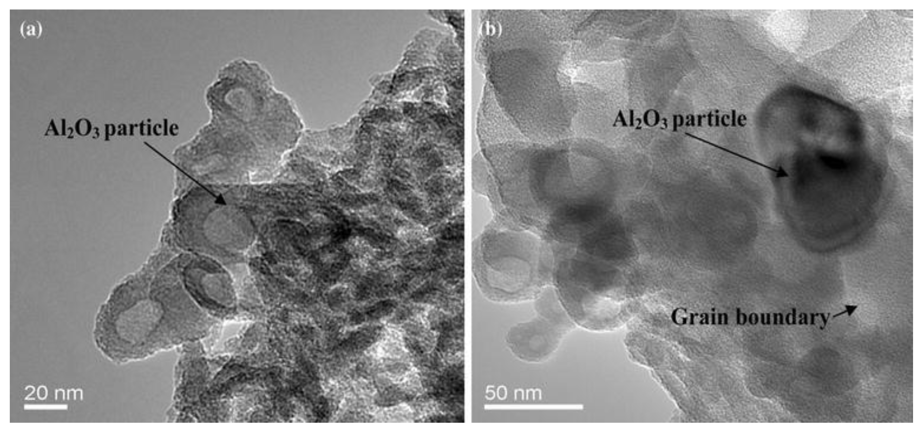
The presence of the nanoparticles in the Ni/Al2O3 matrix is expected to have a pinning effect on the grain boundaries, thereby retarding grain growth as the annealing temperature increased. Smaller particles that are coherent with the lattice are more effective in pining grain boundaries as predicted by the Zener model [22]. When compared to pure nickel coating, the large reduction in hardness and increase of the grain size observed in the pure Ni coating were attributed to grain growth due to the absence of grain boundary restraint provided by the nanoparticles as shown in Figure 12 [16]. Similar observations were made by Chang et al. who evaluated the impact of heat treatment on Ni/SiC coatings produced by electrodeposition [5]. The relationship between hardness, H, and grain size, d, can be explained by the Hall-Petch equation, which is presented in Equation (1) and shows that the hardness of the coating decreases as the grain size is increased. The grain size was determined by calculating the ASTM grain size number.
H = 155 d 0.5 + 101
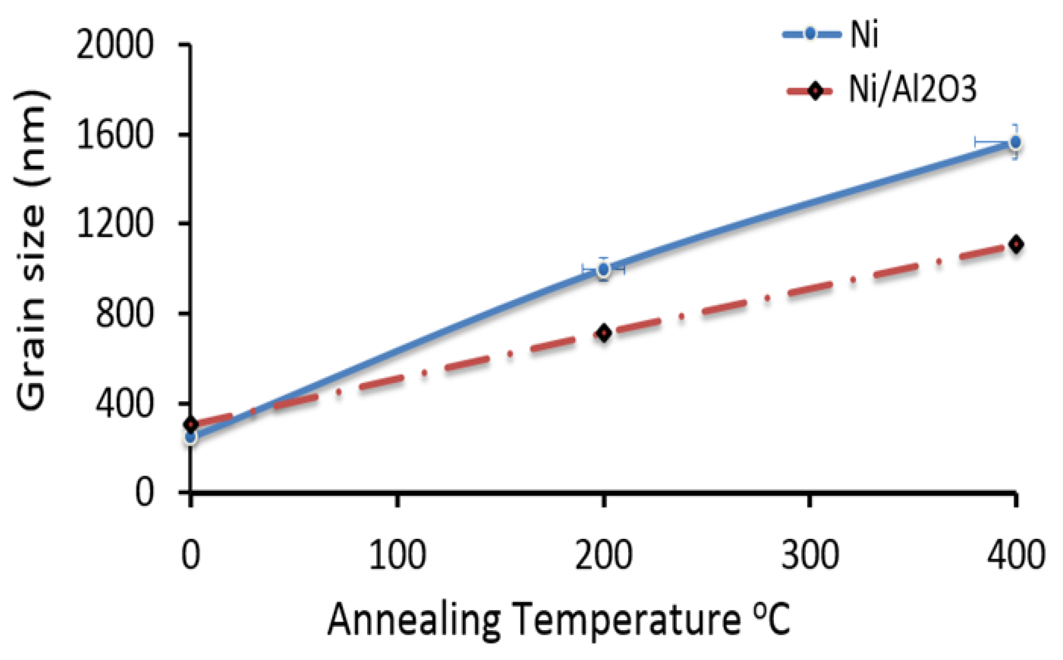
The application of Equation (1) predicts a grain size that is approximately one third the size of the grain sizes presented in Figure 13.

4.2. Grain Growth Kinetics

Grain growth is a thermally activated process; therefore, as the annealing temperature was increased, the expectation was that the grain size would also increase. The Grain Growth Law shown in Equation (2) indicates that the final grain size is dependent on the treatment temperature and the time of exposure.
D n D o n = K o t   e Q R T
where D is the mean grain size, D o is the average size of the grain prior to heat treatment, t is the time, R is gas constant, T is the absolute temperature, Q is activation energy, and n is the grain growth exponent. The grain growth exponent has been shown by several studies to be approximately 2 [24]. In this study, the duration of the heat treatment process was held constant at 30 min for all conditions tested, however, the annealing temperature was varied from 473 K to 673 K to evaluate the effect of annealing temperature on the thermal stability and wear performance of the coatings. The literature shows that the driving force for grain growth is the surface free energy of the grain boundaries. At elevated temperatures, grain coalescence results in a lowering of the surface energies and an increase of grain size.
The addition of nano-sized ceramic particle to the coating should act to retard grain growth, as predicted by Zener pinning [22]. Using the Zener-Smith equation, the drag effect of the particles can be quantified by considering a force balance at the (immovable) particle surface [22] to determine if the particles can pin the boundaries. The primary assumption in applying this equation is that the boundary intersects randomly with the particles. Therefore, the pinning pressure applied by the particle can be calculated using Equation (3).
P d r a g = 3 f γ 2 r
The pressure applied to the particle due to grain growth can be estimated using Equation (4).
P g r a i n   g r o w t h = 2 γ D
By equating the driving force of grain growth to the particle drag force, the point at which grain growth stagnates can be calculated using Equation (5).
P d r a g = P g r a i n   g r o w t h 3 f γ 2 r = 2 γ D
Equation (5) is more popularly referred to as the Zener–Smith equation in the form shown as Equation (6).
D m a x = 4 r 3 f
where D is the maximum diameter of the grain size that can be stopped by a spherical particle of radius r, f is the volume fraction of particles in the material, and γ is the grain boundary energy. From the data collected in the study, the diameter of the Al2O3 particles used in the study was 40 nm. The volume fractions of particles deposited in the coating were 0.18. Using this information, the maximum grain size at the stagnation point for the Ni/Al2O3 coating was calculated to be 370 nm. The calculated values suggest that at annealing temperatures beyond 473 K, grain boundary migration would occur, since the grain sizes measured at this temperature are greater than the stagnation grain size for the Ni/Al2O3 coating.

4.3. Wear Performance of the Coatings

The differences in the wear resistance of the as-deposited coatings tested at this load were attributed to the high ductility of the pure Ni coating. When a tribo-element is made of a ductile material of moderate hardness such as the Ni, the material in the contact region plastically deforms under the combined stresses of compression and shear. Extensive plastic deformation generally introduces a large wear rate, since the wearing surface tends to become rough and protective surface layers are easily destroyed [13]. When the pure Ni coating is compared with the nanocomposite coatings, it is observed that the Ni/Al2O3 coating provided the best wear resistance. The presence of a hard-reinforcing phase in the ductile matrix reduces the ductility of the matrix in the contact region without causing brittleness; additionally, the size of the Al2O3 improves the number of barriers to dislocation motion, which increases the hardness of the coating and reduces the wear rate [25].
The differences observed between the pure Ni-coating and the nanocomposite coatings can be attributed to the higher hardness of the nanocomposite coatings due to the presence of Al2O3 particles. Comparison of the wear performances of the coatings heat-treated to 473 K and 673 K revealed that the depth of the wear scars within the primary stage marginally increased for coatings heat-treated to the higher temperature. Additionally, the wear rate within the secondary stage increased for both the pure Ni coating and the Ni/Al2O3 coating.
While the wear rates of the nanocomposite coatings are lower than that of the pure Ni coating, the overall trend is that for the nanocomposite coatings, the wear rates increased with increasing temperature. The differences in the behavior of the coatings tested at 10 N are likely due to differences in the dislocation density and residual stresses within the coatings as a result of the structural differences between the pure Ni coating and the nanocomposite coatings. The presence of higher dislocation density and residual stress may cause a reduction of the recrystallization temperature in the Ni/Al2O3 coatings, which can increase grain growth rate [22].
Conversely, the results show that the wear rate of the Ni/Al2O3 coating marginally increased with both increasing temperature and load as shown in Figure 8 and Figure 9B. The results suggest that the smaller Al2O3 particles are more effective at pinning grain boundaries at higher temperatures.

5. Conclusions

This study evaluated the effects of heat treatment on the sliding wear behavior of Ni coatings as well as Ni coatings containing Al2O3 nanoparticles. The distribution and percentage of the embedded particles in the metal matrix were examined as well as the microstructure and micro-hardness of the coatings.
XRD analysis of the coatings suggests the presence of an imperfect crystal lattice in the as-deposited Ni/Al2O3 coatings. The presence of nano Al2O3 particles in the coating is also likely to have induced micro-stresses within the as-deposited coatings. Heat treatment of Ni/Al2O3 coatings resulted in a sharpening of the diffraction peaks due to the formation of a more stable crystalline structure with larger grain sizes at a higher heat treatment temperature.
The wear performance measurement indicates that both the load and annealing temperature had a significant effect on the wear rate of the coatings. The results show that the Ni/Al2O3 is the most wear resistant at loads of less than 25 N. The Al2O3 particles added to the Ni/Al2O3 coating were more responsive in maintaining the thermal stability of the Ni/Al2O3 coating. Finally, the results show that the pure Ni and Ni/ Al2O3 coatings are more effective in retaining their mechanical properties at a temperature below 200 °C.

Author Contributions

Conceptualization, K.O.C. and T.I.K.; Formal analysis, Writing—original draft, and Methodology, K.O.C.; Investigation, K.O.C. and M.A.S.; Writing–review & editing, K.O.C. and T.I.K. All authors have read and agreed to the published version of the manuscript.

Funding

This research received no external funding.

Conflicts of Interest

The authors declare that there is no conflict of interest regarding the publication of this paper.

References

  1. De Riccardis, M.F. Ceramic Coatings Obtained by Electrophoretic Deposition: Fundamentals, Models, Post-Deposition Processes and Applications. Ceram. Coat. Appl. Eng. 2012, 2, 43–68. [Google Scholar] [CrossRef] [Green Version]
  2. Besra, L.; Liu, M. A review on fundamentals and applications of electrophoretic deposition (EPD). Prog. Mater. Sci. 2007, 52, 1–61. [Google Scholar] [CrossRef]
  3. Moritz, T.; Eiselt, W.; Moritz, K. Electrophoretic deposition applied to ceramic dental crowns and bridges. J. Mater. Sci. 2006, 41, 8123–8129. [Google Scholar] [CrossRef]
  4. Garcia, I.; Fransaer, J.; Celis, J.-P. Electrodeposition, and sliding wear resistance of nickel composite coatings containing micron and submicron SiC particles. Surf. Coat. Technol. 2001, 148, 171–178. [Google Scholar] [CrossRef]
  5. Wang, S.C.; Wei, W.C.J. Characterization of electroplated Ni/SiC and Ni/Al2O3composite coatings bearing nanoparticles. J. Mater. Res. 2003, 18, 1566–1574. [Google Scholar] [CrossRef]
  6. Bengoa, L.N.; Pary, P.; Egli, W.A. Codeposition of Particles: Role of Adsorption of the Electroactive Species. J. Electrochem. Soc. 2016, 163, 14. [Google Scholar] [CrossRef]
  7. Stroumbouli, M.; Gyftou, P.; Pavlatou, E.A.; Spyrellis, N. Codeposition of ultrafine WC particles in Ni matrix composite electrocoatings. Surf. Coat. Technol. 2005, 195, 325–332. [Google Scholar] [CrossRef]
  8. Farrokhzad, M.A.; Khan, T.I. Sliding wear performance of nickel-based cermet coatings composed of WC and Al2O3 nanosized particles. Surf. Coatings Technol. 2016, 304, 401–412. [Google Scholar] [CrossRef]
  9. Raghavendra, C.R.; Basavarajappa, S.; Sogalad, I. Electrodeposition of Ni-Al2O3 nano composite coating and evaluation of wear characteristics. IOP Conf. Ser. Mater. Sci. Eng. 2016, 149, 012110. [Google Scholar] [CrossRef]
  10. Gül, H.; Kiliç, F.; Aslan, S.; Alp, A.; Akbulut, H. Characteristics of electro-co-deposited Ni-Al2O3 nano-particle reinforced metal matrix composite (MMC) coatings. Wear 2009, 256, 976–990. [Google Scholar] [CrossRef]
  11. Jung, A.; Natter, H.; Hempelmann, R.; Lach, E. Nanocrystalline alumina dispersed in nanocrystalline nickel: Enhanced mechanical properties. J. Mater. Sci. 2009, 44, 2725–2735. [Google Scholar] [CrossRef]
  12. Bicelli, L.P.; Bozzini, B.; Mele, C.; D’Urzo, L. A review of nanostructural aspects of metal electrodeposition. Int. J. Electrochem. Sci. 2008, 3, 356–408. [Google Scholar]
  13. Hou, K.H.; Ger, M.D.; Wang, L.M.; Ke, S.T. The wear behaviour of electro-codeposited Ni-SiC composites. Wear 2002, 253, 994–1003. [Google Scholar] [CrossRef]
  14. Gawad, S.A.A.; Baraka, A.M.; Morsi, M.S.; Eltoum, S.A.A.A. Development of electroless Ni-P-Al2O3 and Ni-P-TiO2 composite coatings from alkaline hypophosphite gluconate baths and their properties. Int. J. Electrochem. Sci. 2013, 8, 1722–1734. [Google Scholar]
  15. Aruna, S.T.; Selvi, V.E.; Grips, V.K.W.; Rajam, K.S. Corrosion- and wear-resistant properties of Ni-Al2O3 composite coatings containing various forms of alumina. J. Appl. Electrochem. 2011, 41, 461–468. [Google Scholar] [CrossRef]
  16. Cooke, K.O. A study of the effect of nanosized particles on transient liquid phase diffusion bonding AI6061 metal-matrix composite (MMC) using Ni/Al2O3 Nanocomposite Interlayer, Metall. Mater. Trans. B Process Metall. Mater. Process. Sci. 2012, 43, 627–634. [Google Scholar] [CrossRef]
  17. Gadhari, P.; Sahoo, P. Effect of Process Parameters on Microhardness of Ni-P-Al2O3 Composite Coatings. Procedia Mater. Sci. 2014, 6, 623–632. [Google Scholar] [CrossRef] [Green Version]
  18. Cooke, K.O. Electrodeposited Nanocomposite Coatings: Principles and Applications; Nova Science Publishers: Hauppauge, NY, USA, 2014; ISBN 978-1-62948-569-0. [Google Scholar]
  19. Cooke, K.O. Effect of Thermal Processing on the Tribology of Nanocrystalline Ni/TiO2 Coatings. J. Emergent Mater. 2018, 1, 165–173. [Google Scholar] [CrossRef] [Green Version]
  20. Cooke, K.O. Parametric Analysis of Electrodeposited Nano- composite Coatings for Abrasive Wear Resistance. Intech Open 2014, 2, 64. [Google Scholar] [CrossRef] [Green Version]
  21. Pavlov, I.; Benea, L.; Celis, J.P.; Vazquez, L. Influence of NANO-TiO2 CO-deposition on the morphology, microtopography, and crystallinity of Ni/NANO-TiO2 electrosynthesized nanocomposite coatings. Dig. J. Nanomater. Biostructures 2013, 8, 1043–1050. [Google Scholar]
  22. Manohar, P.A.; Ferry, M.; Chandra, T. Five Decades of the Zener Equation. ISIJ Int. 1998, 38, 913–924. [Google Scholar] [CrossRef] [Green Version]
  23. Ungár, T. Microstructural parameters from X-ray diffraction peak broadening. Scr. Mater. 2004, 51, 777–781. [Google Scholar] [CrossRef]
  24. Kim, B.; Hiraga, K.; Morita, K. Kinetics of Normal Grain Growth Depending on the Size Distribution of Small Grains. J. Mater. Trans. 2003, 44, 2239–2244. [Google Scholar] [CrossRef] [Green Version]
  25. Kato, K. Wear in relation to friction—A review. Wear 2000, 241, 151–157. [Google Scholar] [CrossRef]
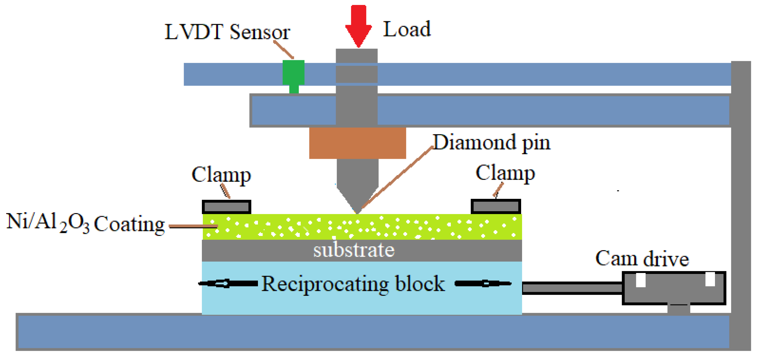
Figure 1. Schematic of the pin-on-plat wear test used in this study.
Jmmp 04 00017 g001
Figure 2. XRD spectra of the coatings treated in oxidizing conditions for heat treatment temperatures of 473 K and 673 K: (A) pure-Ni, (B) Ni/Al2O3.
Jmmp 04 00017 g002
Figure 3. SEM micrograph of (A) surface of the as-deposited Ni/Al2O3 coating; (B) detailed view of point-1; (C) Cross-section of the Ni/Al2O3; and EDS Maps of the cross-section of the Ni/Al2O3 coating, (D) Nickel (Ni), (E) Oxygen (O), (F) Aluminum (Al).
Jmmp 04 00017 g003
Figure 4. SEM micrograph of; (A) cross-section of the as-deposited Ni coating and (B) EDS analysis of the coating cross-section.
Jmmp 04 00017 g004
Figure 5. Confocal micrograph of the coating surfaces before and after heat treatment: (A) as-deposited Ni/Al2O3 coating, (B) Ni/Al2O3 coating heat-treated to 673 K.
Jmmp 04 00017 g005
Figure 6. Micro-hardness measurements of the two types of coatings tested.
Jmmp 04 00017 g006
Figure 7. Confocal micrographs showing the depth of the wear scars recorded for: (A) Ni/Al2O3 as-deposited coating, (B) Ni/Al2O3 heat-treated to 673 K.
Jmmp 04 00017 g007aJmmp 04 00017 g007b
Figure 8. As-deposited coatings tested at 10 N for 30 min.
Jmmp 04 00017 g008
Figure 9. Wear rates of the coatings tested as a function of heat treatment temperature.
Jmmp 04 00017 g009
Figure 10. SEM micrograph of the wear track for Ni (AC) and Ni/Al2O3 (DF) coatings tested at 10 N, 25 N and 40 N.
Jmmp 04 00017 g010
Figure 11. SEM micrograph of the wear track for Ni and Ni/Al2O3 coatings: (A) As-deposited, (B) Heat treated to 473 K, (C) Heat treated to 673 K; and Ni coatings (D)As-deposited, (E) Heat treated to 473 K, (F) Heat treated to 673 K.
Jmmp 04 00017 g011
Figure 12. TEM micrographs of the nano-composite coatings (a) distribution of nanoparticles in the coating (b) Nanoparticle embedded at the grain boundary.
Jmmp 04 00017 g012
Figure 13. Effect of annealing temperature on grain size.
Jmmp 04 00017 g013
Table 1. The average surface roughness of the coatings before and after heat treatment.
Heat Treatment TemperatureRoughness (µm)
NiNi/Al2O3
As-deposited0.1570.547
473 K0.1620.624
673 K0.2340.659